

Page 1
COMPU
TER PROCESS CONTROL
S
®
technical bulletin
Control Link RSC Installation Instructions
Overview
The Control Link Refrigeration System Controller (CL-RSC) is an electronic device that can control all functions
of a single-compressor refrigeration system, including refrigeration, defrost, and alarming. Scheduled defrost and
case light control is also possible with the addition of an expansion real-time clock module (P/N 618-2082, available separately).
The CL-RSC reads discharge air and defrost termination temperature from sensors mounted in the case. The CLRSC may control two external relays (compressor plus one configurable relay) directly from its two onboard drycontact relay outputs, or it may use a pluggable expansion output board (P/N 618-1120 for compressor control, or
618-2085 for refrigeration solenoid control) for activating case system components.
NOTE: For information about networking Control Link RSC with E2, refer to Technical Bulletin 026-4602
available on the Internet at http://www.emersonretailsolutions.com/library
Mounting
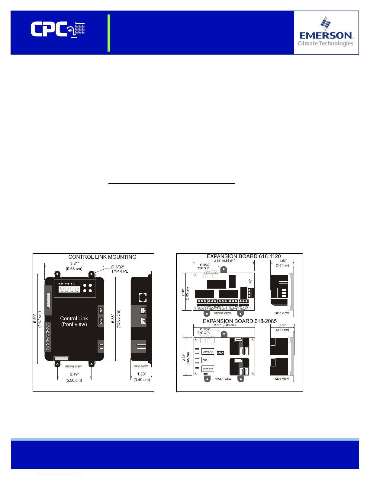
Main Module / Relay Expansion Board
The Control Link main module and relay expansion boards are designed for mounting on a refrigerated case or in
an enclosure near the case. The output board connects to the main module with a ribbon cable and therefore should
be mounted directly below the main module using the attached stand-off bracket. Figure 1 shows module dimensions, and Figure 2 shows relay expansion board dimensions.
.
Figure 1 - Control Link Module Mounting
Document Part # 026-4600 Rev 3 23-APR-2008 Page 1 of 8
©2007 Emerson Climate Technologies Retail Solutions, Inc. This document may be photocopied for personal use.
Visit our website at http://www.emersonretailsolutions.com/ for the latest technical documentation and updates.
Figure 2 - Expansion Board Mounting
Page 2
technical bulletin
Control Link RSC Installation Instructions
Main Module and Expansion Board Environment Specs
Operating Temperature: 0 — 60°C (14—140°F)
Operating Humidity: 90% RH non-condensing
Storage Temp: -30—65°C (-22—149°F)
Max Power Consumption: 15W (Control Link w/expansion board)
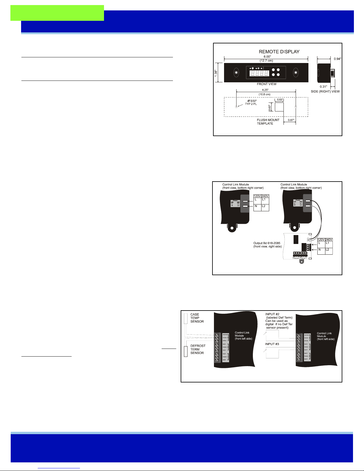
Remote Display Mounting
The remote display is designed to be mounted on an accessible part of a
refrigerated case or enclosure, no more than 25 feet from the main module. If flush mounting on a flat surface such as the front of a case or
enclosure, punch a 5/8” square hole in the surface to allow the protruding RJ45 jack to recess, and then drill 5/32” holes for the mounting
screws using the remote display itself as a template. Figure 3 shows the
dimensions.
Power down the main module before connecting the remote display. Use CAT5 wiring with RJ45 connectors to connect
the Main Module with the Remote Display. Do not exceed a maximum length of 25 feet.
Figure 3 - Remote Display Mounting
Wiring
Power (Control Link Module without output board, or with
618-2085 output board)
When the Control Link module is used without an output board or with
the 816-2085 output board, connect 120-240 VAC 50-60 Hz line voltage
to the spade lug connectors on the lower right side of the Control Link
module (Figure 4). The expansion board is powered from the CL-RSC
and requires no external power connection.
Power (Control Link Module with 618-1120 output board)
Figure 4 - Control Link Power
When the 618-1120 output board is used with a Control Link module,
connect the L and N spade lug terminals on the module to the L and N spade lug terminals on the output board (Figure 4).
Connect 120-240 VAC 50-60 Hz line voltage to the screw terminals labeled L and N on the output board. Do not connect
any wire to the middle terminal.
Sensors
Case temperature and defrost termination temperature sensors must be wired to the top three-terminal connector on
the left side of the Control Link module. Use only CPC
NTC 10k thermistors. The defrost termination sensor must
be a 10k thermistor, not a temperature switch. Wire as
shown in Figure 5. Mount the case temp sensor in the discharge air stream for the case. Mount the defrost termination sensor near the evaporator coil.
Figure 5 - Sensor Wiring
Inputs for switches to activate setpoint shift and initiate defrost may be wired to Input 3, and also to the Def Term input
(Input #2) if no defrost termination sensor is being used. The functions of these switches are determined by parameters
SI2d and SI3d in Advanced Parameters.
Document Part # 026-4600 Rev 3 23-APR-2008 Page 2 of 8
©2007 Emerson Climate Technologies Retail Solutions, Inc. This document may be photocopied for personal use.
Visit our website at http://www.emersonretailsolutions.com/ for the latest technical documentation and updates.
Page 3
technical bulletin
Control Link RSC Installation Instructions
CL-RSC Onboard Outputs
If using CL-RSC without an expansion board, wire the outputs to the two-wire terminals
on the right side of the control unit, as shown in Figure 6. Each of these output points are
rated to a maximum of 3A @ 250V. For loads greater than 3A, use the outputs to energize
external relays for compressors, defrost, and case lights.
Expansion Board Wiring
Both types of relay output boards connect to the Control Link main module using an 8-pin
ribbon cable. Plug the cable onto the Expansion Board connector at the bottom of the main
module.
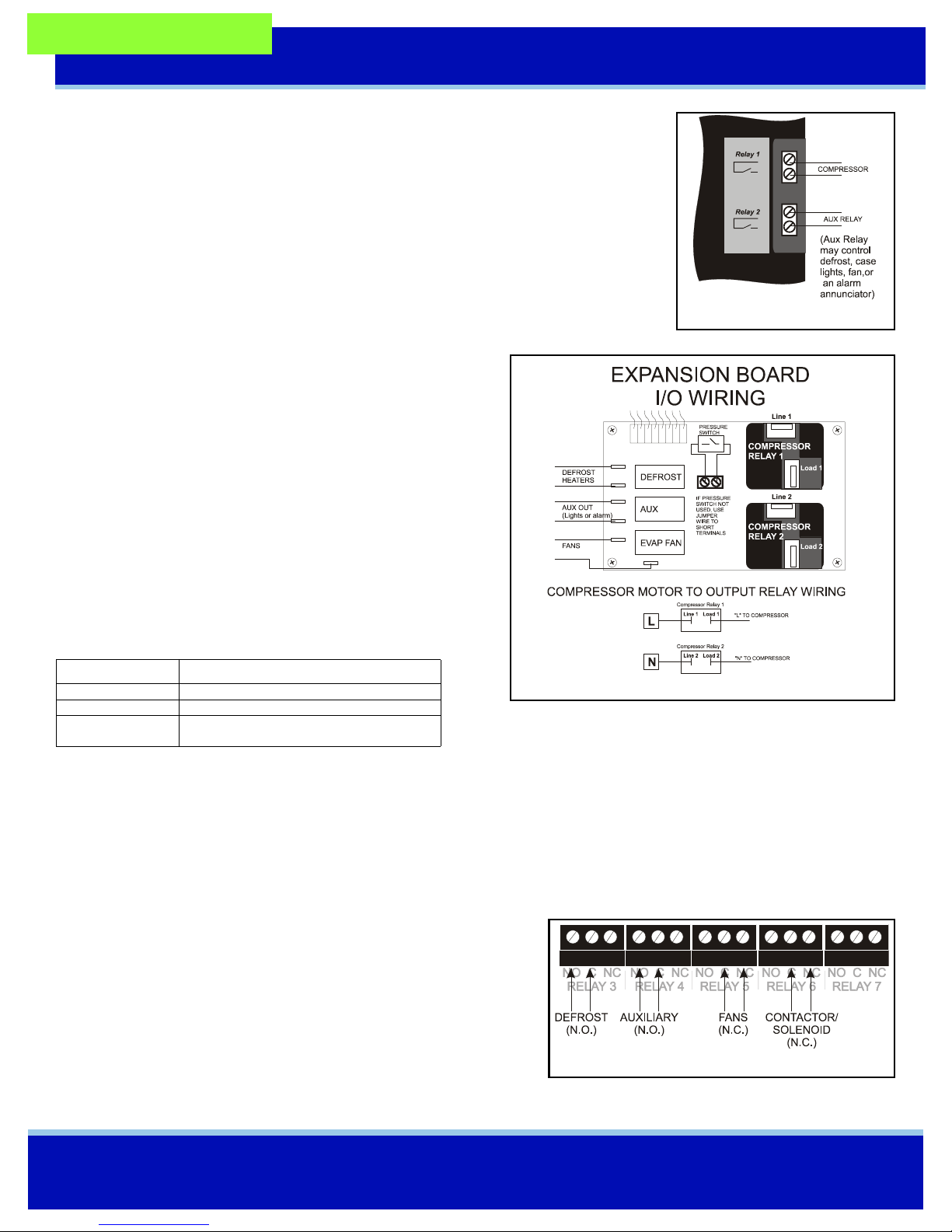
Relay and Pressure Switch Wiring (618-2085 Output
Board)
Defrost, Fans, and Aux Relay (
Using spade lugs, connect the defrost heater(s), case fans, and
auxiliary output (either case lights or an alarm device) to the
three relays on the left side of the relay output board as shown in
Figure 7. Refer to Tabl e 1 for relay ratings.
Figure 6 - CL-RSC Outputs
Compressor Relays
The Control Link uses two relays on the output board to control
the compressor. Line voltage must be connected to the Line 1 and
Line 2 connectors on relays 1 and 2 respectively. The Load 1 and
Load 2 connectors are wired to the compressor. Figure 7 shows
the wiring diagram. Refer to Table 1 for relay ratings.
Relays Output Board 618-2085
Defrost and Aux 10A at 120VAC
Fan 208-230VAC 2 FLA 4 LRA
Compressors 208-230VAC 10FLA 60LRA
115VAC 13FLA 86LRA
Table 1 - Relay Ratings (Output Board 618-2085)
Pressure Switch Wiring
Figure 7 - Expansion Board Output Wiring
If desired, a pressure switch may be used to deactivate the compressor if a high/low suction pressure condition occurs.
Remove the jumper wire and connect this switch to the dual screw-terminal Pressure Switch connector located in the middle of the relay output board. See Figure 7. If not used, these terminals must be jumpered in order for the board to work.
The pressure switch must be N.C. (normally closed) type.
Relay Wiring (618-1120 Output Board)
Use the Form C contactors on the output board points labeled RELAY
3 through RELAY 6 to connect the defrost, auxiliary, fans, and solenoid or contactor. Refer to Figure 8, and refer to Tab le 2 for relay rat-
ings and fail-safe positions.
Figure 8 - Expansion Board Output Wiring
Document Part # 026-4600 Rev 3 23-APR-2008 Page 3 of 8
©2007 Emerson Climate Technologies Retail Solutions, Inc. This document may be photocopied for personal use.
Visit our website at http://www.emersonretailsolutions.com/ for the latest technical documentation and updates.
Page 4

technical bulletin
Control Link RSC Installation Instructions
# Function Fail-Safe Output Board 618-1120
RELAY 3 Defrost N.O. 10A-N.C. or 12A N.O. @ 120-240 VAC
RELAY 4 Auxiliary N.C. 10A-N.C. or 12A N.O. @ 120-240 VAC
RELAY 5 Fan N.C. 1/2 hp N.O. or N.C., 120VAC
1 hp N.O. or N.C., 240VAC
RELAY 6
&
RELAY 7*
* Relay 7 is not used by the Control Link RSC but has the same ratings as Relay 6
Table 2 - Relay Ratings (Output Board 618-1120)
Contactor
or Solenoid
N.C. Contactor Solenoid Pilot Duty
Inrush Steady-State Inrush Steady-State VA
24VAC 2.5A 0.3A 4A 2A 50
120VAC 0.5A 0.06A 0.8A 0.4A 50
240VAC 0.25A 0.03A 0.4A 0.2A 50
CL-RSC Operation
The Display
The primary means of interaction with the CL-RSC system during programming and operation will be the display on the front of the Control
Link module (or the remote display, if one is being used). Figure 9
shows the display used on both the module and the remote display.
Seven-Segment Display
The four-digit seven-segment display is the primary means a technician
or operator will use for viewing temperatures and alarm codes, and programming setpoints.
Figure 9 - CL-RSC Display
Status LEDs
The three LEDs above the seven-segment display show the status of the compressor relay, the fan relay, and whether or not
a setpoint shift is active (lit if setpoint shift is active).
Buttons
The four buttons to the right of the seven-segment display are used to program the CL-RSC, select temperatures and alarms
for viewing, and perform other functions such as alarm silencing and manual defrost.
Modes of Operation
Start-Up
Compressor operation will be suspended after power-up based on the value of the CSUd parameter (default 10 minutes).
After this delay, the CL-RSC resumes normal refrigeration control. To prevent nuisance alarms when the case is first started
up, no high temperature case alarms will be generated until 120 minutes after the start of the first cooling cycle.
Normal Operation (Refrigeration)
When in refrigeration mode, the CL-RSC energizes the compressor relay when the case temperature is above the setpoint,
and de-energizes it when the case temperature setpoint is satisfied. The fan relay is activated and de-activated the same way
as the compressor relay, unless the CL-RSC has been programmed to keep the fans always ON.
Alarms During Refrigeration
If the case temperature sensor value falls below the low temperature setpoint or rises above the high temperature setpoint,
the alarm relay (if defined) will energize, and the display will show the alarm code. The energized alarm relay and display
Document Part # 026-4600 Rev 3 23-APR-2008 Page 4 of 8
©2007 Emerson Climate Technologies Retail Solutions, Inc. This document may be photocopied for personal use.
Visit our website at http://www.emersonretailsolutions.com/ for the latest technical documentation and updates.
Page 5

technical bulletin
Control Link RSC Installation Instructions
code will continue until the temperature returns to normal (1°F below high temp alarm setpoint or 1°F above low temp setpoint) or until the Alarm Silence button is pressed (alarm is suspended for 5 minutes, then will reoccur if problem is still
active).
Defrost Operation
Defrost cycles are initiated at the times programmed in the CL-RSC. During defrost, the compressor relay is de-energized,
and the defrost relay is energized. The defrost relay will be de-energized when the defrost termination temperature is
reached or until the programmed defrost duration has elapsed (whichever occurs first). While the defrost relay is energized,
the display will show dEF instead of the case temperature.
If a defrost drip duration has been programmed, immediately after defrost termination the compressor relay will remain
OFF for an amount of time to allow moisture to drain off the coil. During this time, the display will read drIP. When the
drip time is over, refrigeration will resume. Fans may be either off or on during defrost, based on user programming.
Manual Defrost
A manual defrost may be initiated at any time by holding the SET button for 10 seconds until the dEF message is shown on
the display. Defrost will begin immediately and terminate normally. If one of the auxiliary inputs is configured as a manual
defrost switch, a contact closure on the switch will also initiate a manual defrost.
Compressor Fail-Safe Mode
If the case temperature sensor fails, the CL-RSC will operate in a fail-safe mode that cycles the compressor ON and OFF at
a user-defined regular interval. The ON/OFF rate is determined by setting parameters CSFP and CSFO in the CL-RSC. CSFP
sets the interval period, and CSFO sets the amount of time during that period the compressor will be ON.
For example, if during fail-safe you want the compressor to alternate being ON for three minutes and OFF for seven minutes, set CSFO to 3 and CSFP to 10. This will cause the compressor to be ON for three minutes of the 10 minute interval, and
OFF for the remaining seven minutes.
Output Board Comm Loss/Power Loss Fail-Safes
The 618-1120 Output Board has Form C contacts. The fan and contactor/solenoid outputs are wired to the normally closed
(N.C.) contacts on the board, meaning refrigeration and fan outputs will fail to the CLOSED state when power is lost or
communication with the RSC is lost. The defrost and auxiliary outputs are wired to the normally open (N.O.) contacts,
meaning these fan outputs will fail to the OPEN state.
Auxiliary Relay Control
The auxiliary relay on the Relay Expansion board, or relay #2 on the Control Link main module, may be used to control
various functions:
• Defrost (only an option for relay #2 if no Expansion Board is used).
• Lighting Control: Up to six ON/OFF times per day may be programmed for case lights. If not connected to an E2, the Control
Link main module will require a real-time clock module to perform lighting control.
• Case Fans: Fans can be programmed to be always ON, or ON only when the compressor is ON. Other features include programmable fan state during defrost, and suspension of fan activation after defrost based on time and/or case temperature.
• Alarm: The relay will close when an alarm is active on the Control Link main module.
Document Part # 026-4600 Rev 3 23-APR-2008 Page 5 of 8
©2007 Emerson Climate Technologies Retail Solutions, Inc. This document may be photocopied for personal use.
Visit our website at http://www.emersonretailsolutions.com/ for the latest technical documentation and updates.
Page 6

technical bulletin
Control Link RSC Installation Instructions
Programming the CL-RSC
General Parameters
General parameters are used by technicians and operators to set control setpoints, defrost schedules, time and date.
Before changing parameters, clear any active alarms by pressing the Alarm Silence button. Press (SET) and hold for five
seconds. If general mode programming has been password protected, you will see PASS on the display. Press (SET) and
use the arrow keys to increment the password number until the correct password is shown, and then press (SET). (If general
parameters are not password protected, PASS will not appear on the display).
The display will show the first programmable parameter: CSP (case temperature set point). The arrow keys may be used to
scroll through the list of general parameters. To change the value of any parameter:
1. Select the parameter using the arrow keys (until the code is shown).
2. Press (SET).
3. The current value of this parameter will be displayed. Use the arrow keys to change the value.
4. Press (SET) to accept value.
5. Repeat steps 1 - 4 until all set points have been properly configured.
6. When finished, press (SET) again for five seconds to save changes and exit. The display will blank for one second and then revert to normal display if the save was successful.
7. To cancel all changes, press and hold (SILENCE) for five seconds, or leave controller idle for 60 seconds. You will lose all setpoint changes
made since you entered general programming mode.
WARNING!
To make changes permanent, you MUST press and hold (SET) for five
seconds. Leaving the controller idle for 60 seconds will log you out and
cancel all your setpoint changes.
NOTE: Parameters in General Parameters shaded gray are only shown if the real-time clock module is being used.
General Parameters
Code Description Min Max
CSP
CLSt
yEAr
nO
dAy
dEFt
dEFd
ndFt
dUPU
ddAP
drip
dCPd
dF1 -dF12
tAH
tAL
Adtd
Temp control set point (deg F, can be displayed in deg C)
Clock time set (military). UP button adjusts minutes. DOWN adjusts hours..
Year set (last two digits of year)
Month set
Day set
Defrost termination temperature (deg F, can be displayed in deg C)
Defrost cycle duration (minutes)
Minimum defrost time. After defrost begins, the RSC will remain in defrost for the Minimum Defrost Time regardless of whether or not termination is being called for. A zero in this parameter disables the minimum defrost feature.
Defrost upon power-up? (if yes, initiates defrost cycle after power restore)
Defrost delay after powerup (minutes). Visible only if dUPU is set to yEs.
Compressor OFF delay after defrost (minutes)
Defrost cycles per day (if set to 0, no dFx schedule times will be shown)
The number of dFx parameters in the list will be equal to parameter dCPd. Starting with dF1, enter the time of day
each scheduled defrost cycle will begin.
High temperature alarm setpoint. (deg F, can be displayed in deg C)
Low temperature alarm setpoint (deg F, can be displayed in deg C)
Alarm delay after defrost (temp alarms are suspended for this many minutes after end of defrost)
-40 100 25
05 99 05
1 12 1
1 31 1
-40 100 35
112010
0600
no yES no
01205
06010
01210
00:00 23:59
-40 100 100
-40 100 -40
06010
see desc.
Default
Document Part # 026-4600 Rev 3 23-APR-2008 Page 6 of 8
©2007 Emerson Climate Technologies Retail Solutions, Inc. This document may be photocopied for personal use.
Visit our website at http://www.emersonretailsolutions.com/ for the latest technical documentation and updates.
Page 7

technical bulletin
Control Link RSC Installation Instructions
General Parameters
Code Description Min Max
AdEL
Sft
Alarm delay for high/low temp alarm. Temp must remain out of alarm setpoint range for this number of minutes
before an alarm can occur.
Software revision number. This field is read-only.
06010
Advanced Parameters
Advanced parameters are used to change higher-level parameters. Selecting and changing advanced parameters works the
same way as general parameters, except they are accessed in a different way and require entering a different password.
Before changing parameters, clear any active alarms by pressing the Alarm Silence button. Press and hold the UP and
DOWN buttons simultaneously for five seconds to enter advanced programming mode. The display will show APAS. Press
(SET) and use the arrow keys to select the correct password (default is 0000), and press (SET) to enter it.
Advanced Parameters
Code Description Min Max
rYbd
LF
r2Fn
F C
dIFF
HSP
LSP
SI2
SI2d
SI3
SI3d
CAL1 CAL2 CAL3
FAnO
FANd
FOtP
FdAd
CSUd
COt
COnt
CSFP
CSFO
CSS
drt
Add
Selects whether outputs will be controlled from the RSC’s onboard relays (no) or the expansion board (yES).
Line frequency (Hz)
Function of the aux relay (relay #2) on the RSC. dEF=Defrost, FAn=case fans, LCon=lighting control,
ALAr=alarm. Visible only when rYbd = no.
Temperature units (this affects units for both display and setpoints)
Control temp setpoint differential (deadband around setpoint) in degrees
High temp control setpoint limit (CSP cannot be set higher than this value) in degrees
Low temp control setpoint limit (CSP cannot be set lower than this value) in degrees
Determines type of sensor on input #2 (defr. term). If ntc is selected, input will be used as defrost term; if dGt
selected, input will be used as an auxiliary input (whose function is determined by
If input #2 (defr. term) is dGt, determines function of digital input. SS = setpoint shift (“ON” causes the value of
SI2d).
CSS to be added to set points), IdeF = start manual defrost.
Determines type of sensor on input #3. ntc = 10K CPC thermistor, dGT = digital sensor.
If input #3 is dGt, determines function of digital input. SS = setpoint shift (closure causes the value of CSS to be
added to set points),
Va l u e o f CAL1, CAL2, and CAL3 parameters are added to their respective temp inputs for calibration purposes.
Fan during normal mode. no = on only when compressor is on, yES = always on during normal mode. Visible
only if fan output is present (i.e. expansion board is being used, or
Fan during defrost. no = fan off, yES = fan on during defrost. Visible only if the RSC is controlling both fan and
defrost with an expansion board.
Fan ON temp setpoint. After defrost, temp must fall below this setpoint before fans will be allowed to activate.
Visible only if the RSC is controlling both fan and defrost with an expansion board.
Fan activation delay after defrost, in seconds. (if zero, FOtP is used after defrost; if non-zero, FdAd is
used).Visible only if the RSC is controlling both fan and defrost with an expansion board.
Compressor ON delay after power-up (minutes)
Minimum compressor OFF time (minutes)
Minimum compressor ON time (minutes)
Compressor fail-safe period. When case temp sensor fails, compressor will cycle ON/OFF over this period (see
IdeF = initiate manual defrost.
r2Fn=FAn).
CSFO).
Amount of time in the CSFP fail-safe period that the compressor will be ON (minutes).
Control setpoint shift - value is added to all control and alarm setpoints when a setpoint shift input is closed.
Minimum time between defrosts, in minutes. Visible if a defrost output is present (using expansion board, or
r2Fn= dEF).
Alarms display disabled. yES = no alarm codes displayed on the RSC. no = alarms enabled.
no yES no
50 60 60
dEF ALAr dEF
FC F
1101
-40 100 100
-40 100 -40
ntc dGt ntc
IdeF
SS
ntc dGt ntc
IdeF
SS
-10 10 0
no yES no
no yES no
-40 100 32
012010
01510
0155
0151
06010
0605
-140 140 0
0 120 60
no yES no
Default
Default
IdeF
IdeF
Document Part # 026-4600 Rev 3 23-APR-2008 Page 7 of 8
©2007 Emerson Climate Technologies Retail Solutions, Inc. This document may be photocopied for personal use.
Visit our website at http://www.emersonretailsolutions.com/ for the latest technical documentation and updates.
Page 8

technical bulletin
Control Link RSC Installation Instructions
Advanced Parameters
Code Description Min Max
ArA
LIOn LIOF
.
.
L6On L6Of
LOC
PASS
APAS
rbtp
For the expansion board, sets the function of the auxiliary relay. ALAr =close on alarm, LCOn = lighting control.
Visible only if
Visible only if ArA=LCon or r2Fn=LCon. There are six ON/OFF pairs where you may specify times of day for
turning the lighting control relay ON and OFF. Enter the first ON time of the day in the
OFF time in the
rYbd=yES.
L1On field and the first
L1OF field. If necessary, continue entering ON/OFF times in the L2On / L2Of fields, then
L3On / L3Of, etc. Leave all unused schedule time pairs set to 0:00 to disable them.
General parameter password enable. If yES, user must enter password to change general parameters.
Password for general programming. If 0000, no password is required.
Password for advanced programming.
Relay board type. 0-St for the “standard” (618-2085) board, 1-gp for the “general purpose” (618-1120) board.
ALAr LCOn ALAr
0:00 23:59 0:00
no yES no
0000 9999 0000
0000 9999 0000
0-St 1-gp 0-st
Default
Restore to Defaults
SETPOINT RESET BUTTON
(PRESS & HOLD 15 SECONDS)
The blue button located on the top of the Control Link main module (see Figure 10) may be used to
restore the Control Link RSC to its “default setpoints,” which can be either the RSC’s factory default
setpoints (as shown in the “Default” columns of the General and Advanced Parameters) or a customer-specific set of defaults programmed using the Control Link PC tool. Do NOT
press the
Restore to Defaults button unless you are sure what default values will be restored.
To perform a restore, press and hold this button for 15 seconds. The display will flicker briefly to
CONTROL LINK
(FRONT VIEW)
indicate the command to reset was received. Power down the Control Link, wait 5 seconds, and
restore power.
Figure 10 - Reset Button
Alarms
There are ten different alarms that may occur in a CL-RSC. When an alarm is detected, CL-RSC takes the following actions:
• Displays a four-character error code on the LED display (unless parameter “Add” is set to “yES”
• Closes the Aux relay (if parameter “ArA” is set to “ALAr”)
• Uses fail-safe modes and settings to compensate for the alarm condition and attempt to keep the system running until repair can be done.
Alarm Codes
Code Description
tS1O ts20 ts30
tS1S ts2s ts3s
HtP
LtP
dtt
rLy
Open sensor alarm for sensor #1 (case temp), sensor #2 (defr. term), or sensor #3. When tS1O is active, CL-RSC uses CSFP and CSFO to pulse the
compressor ON and OFF as a fail-safe. When
Short sensor alarm for sensor #1 (case temp), sensor #2 (defr. term), or sensor #3. When tS1S is active, CL-RSC uses CSFP and CSFO to pulse the
compressor ON and OFF as a fail-safe. When
High temperature alarm setpoint was reached after the Adtd(def. delay) or AdEL (normal delay) elapsed. No fail-safe actions.
Low temperature alarm setpoint was reached after the Adtd(defrost delay) or AdEL (normal delay) elapsed. No fail-safe actions.
The case temperature did not reach the defrost termination temperature setpont (dEFt) before the defrost cycle time finished. No fail-safe actions.
Compressor fault detected.
ts20 is active, defrosts will not terminate by temperature and will last the full duration (dEFd).
ts2s is active, defrosts will not terminate by temperature and will last the full duration (dEFd).
Clearing Alarms
To clear an alarm and cause the CL-RSC to resume normal operation, press the Alarm Silence button. The alarm message will disap-
pear, the Aux relay will open (if parameter “ArA” is set to “ALAr”), and the CL-RSC will attempt to resume normal operation. If the
condition or conditions that caused the alarm are still present, the alarm will reoccur after the appropriate alarm delays have elapsed.
Document Part # 026-4600 Rev 3 23-APR-2008 Page 8 of 8
©2007 Emerson Climate Technologies Retail Solutions, Inc. This document may be photocopied for personal use.
Visit our website at http://www.emersonretailsolutions.com/ for the latest technical documentation and updates.
 Loading...