

Page 1
Control Link ACC Anti-Condensate Controller System
Installation and Operation Manual
026-4704 Rev 6
Page 2

Page 3

Emerson
1065 Big Shanty Road NW, Suite 100
Kennesaw, GA 30144 USA
Phone 770-425-2724
Fax 770-425-9319
Page 4

Page 5

Contents
1 OVERVIEW ................................................................................................................................................................... 1
2 COMPONENTS ............................................................................................................................................................. 1
2.1. C
ONTROL LINK ACC (P/NS 815-6100 AND 815-6105) ............................................................................................... 1
2.2. D
EWPOINT SENSOR (P/N 814-6115) ........................................................................................................................... 2
2.3. D
OOR FRAME TEMPERATURE SENSOR (P/N 281-0002) .............................................................................................. 2
3 MOUNTING THE CONTROL LINK ACC ............................................................................................................... 3
4 CALCULATING MAXIMUM AMBIENT TEMPERATURE ................................................................................. 4
5 WIRING THE CONTROL LINK ACC ...................................................................................................................... 6
5.1. P
OWER AND HEATER ELEMENT WIRING ..................................................................................................................... 6
5.2. R
ATINGS AND CURRENT PROTECTION.......................................................................................................................... 6
6 MOUNTING AND WIRING THE SENSORS ........................................................................................................... 7
6.1. T
HE DEWPOINT SENSOR ............................................................................................................................................... 7
6.1.1. Placement.............................................................................................................................................................. 7
6.1.2. Note About Using RTV Sealants ........................................................................................................................... 7
6.1.3. Dewpoint Sensor Mounting Dimensions............................................................................................................... 8
6.1.4. Dewpoint Sensor Wiring ....................................................................................................................................... 8
6.1.5. Dewpoint Sensor Storage...................................................................................................................................... 9
6.2. T
HE DOOR FRAME TEMPERATURE SENSOR ............................................................................................................... 10
6.2.1. Placement............................................................................................................................................................ 10
7 NETWORK WIRING AND CONFIGURATION.................................................................................................... 11
7.1. N
ETWORK CONNECTION TO E2 ................................................................................................................................. 11
7.2. E2 S
ETUP OF CONTROL LINK ACC DEVICES ............................................................................................................. 11
7.2.1. Setup Network Ports............................................................................................................................................ 11
7.2.2. Add and Connect Control Link ACCs - E2 Firmware Revision Prior to 2.8...................................................... 12
7.2.3. Add and Connect Control Link ACCs - E2 Firmware Version 2.8 and above ................................................... 13
7.3. W
7.4. MODBUS N
IRING TYPES............................................................................................................................................................ 15
ETWORK AND DAISY-CHAINING ............................................................................................................ 16
7.4.1. Step 1: Disconnect Power to the Control Link ACC and Open the ACC Enclosure .......................................... 16
7.4.2. Step 2: Connect the MODBUS Network Cable................................................................................................... 16
7.4.3. Step 3: Set the Network Address ......................................................................................................................... 16
7.4.4. Step 4: Set the Network Baud Rate and MODBUS Parity ................................................................................. 17
7.4.5. Step 5 - Terminate the End Devices ................................................................................................................... 18
7.4.5.1. Termination Block Network ............................................................................................................................................. 18
7.4.6. Step 6 - Connect a Dewpoint Sensor to Control Link ACC(s) on the Network................................................... 18
7.4.7. Step 7 - Set the Setpoint Temperature Offset ..................................................................................................... 19
7.4.8. Step 8 - Network Configuration Is Complete - Restore Power to the ACC ........................................................ 19
8 THE ACC HAND-HELD TERMINAL INTERFACE............................................................................................. 21
8.1. HHT H
8.2. K
8.3. H
8.4. C
ARDWARE OVERVIEW..................................................................................................................................... 21
EYS AND FUNCTIONS .............................................................................................................................................. 21
AND HELD TERMINAL EXPANSION BOARD ............................................................................................................ 22
ONNECTING THE HHT ADAPTER BOARD ................................................................................................................. 22
8.4.1. HHT Home Screen ............................................................................................................................................. 22
8.5. HHT I
NTERFACE NAVIGATION ................................................................................................................................... 23
Table of Contents • v
Page 6

8.5.1. ACC HHT Network Setup.................................................................................................................................... 23
8.5.1.1. Modes of ACC Addressing ............................................................................................................................................... 23
8.5.2. The ACC HHT Interface...................................................................................................................................... 23
8.5.2.1. ACC Start Screens ............................................................................................................................................................ 23
8.5.3. ACC Status Screens............................................................................................................................................ 24
8.5.3.1. Input Status Screen .......................................................................................................................................................... 24
8.5.3.2. Output Status Screen......................................................................................................................................................... 24
8.5.4. ACC Configuration Screens................................................................................................................................ 24
8.5.4.1. HHT Changes When ACC is Connected to E2 ................................................................................................................ 24
8.5.4.2. HHT Changes When ACC is Stand-Alone ....................................................................................................................... 24
8.5.4.3. The Main Selection Screen .............................................................................................................................................. 24
8.5.5. Upgrading ACC Using HHT............................................................................................................................... 26
8.5.6. Changing ACC Address Using HHT................................................................................................................... 26
8.5.7. Exit HHT Mode ................................................................................................................................................... 26
9 OPERATION................................................................................................................................................................ 27
9.1. C
ONTROL LINK ACC STATUS LEDS .......................................................................................................................... 27
9.1.1. Heater Status LED .............................................................................................................................................. 27
9.1.2. General Status LED ............................................................................................................................................ 27
9.1.3. TX and RX Status LEDs ...................................................................................................................................... 28
10 ERROR MODES........................................................................................................................................................ 29
10.1. P
10.2. P
10.3. P
10.4. P
10.5. P
RIORITY 1: FAIL: OVER TEMP ............................................................................................................................ 29
RIORITY 2: FAIL: TEMP SENS ............................................................................................................................. 29
RIORITY 3: FAIL: DEWPT SNS ............................................................................................................................ 29
RIORITY 4: FAIL: FLASH/CLK............................................................................................................................. 29
RIORITY 5: FAIL: CONFIGURE............................................................................................................................ 29
11 TROUBLESHOOTING CONTROL LINK ACCS AND THE ECT MODBUS NETWORK ........................... 30
11.1. I
F CONTROL LINK ACC IS OFFLINE ......................................................................................................................... 30
12 SPECIFICATIONS ................................................................................................................................................... 31
13 PART NUMBERS AND DESCRIPTIONS ............................................................................................................. 32
vi • Control Link ACC I&O Manual 026-4704 Rev 6
Page 7
1Overview
The Control Link ACC Anti-Condensate
Controller System is a controller for anti-sweat
heaters inside glass door cases and can be used either
as a stand-alone device or networked with the E2
controller over the MODBUS network. There are two
available models of the Control Link ACC:
• UL Listed version 7A/10A (P/N 815-6100)
• UL Recognized version 18A/26A/30A
(P/N 815-6105) - requires an additional heat sink
The Control Link ACC varies the anti-sweat
heaters based on the temperature of the door frame
and surrounding dewpoint, providing the most
efficient control possible in order to maximize energy
savings.
2 Components
2.1. Control Link ACC
(P/Ns 815-6100 and
815-6105)
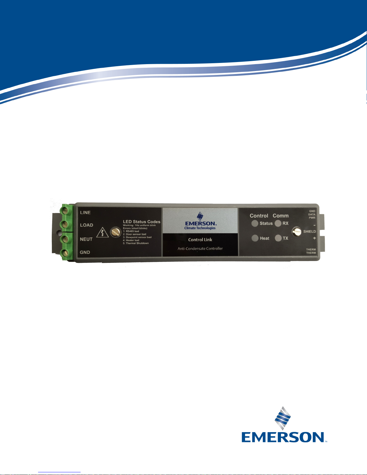
The Control Link ACC (Figure 2-1) handles all
aspects of anti-sweat heater control and uses solidstate switching to control the heaters. The on-board
processor calculates the required heater ON time
based on the dewpoint and door frame temperature
readings, and controls an on-board Triac to activate
and deactivate the heaters.
The controller is designed to mount in the mullion
between glass doors or in any other suitable electrical
enclosure, such as a raceway or on the top of the case.
The door frame temperature sensor and dewpoint
sensor are mounted remotely and connect to this
controller with cable harnesses.
Four LEDs can be viewed on the front of the
plastic enclosure. They indicate the general status,
heater ON, MODBUS network transmit (TX), and
MODBUS network receive (RX).
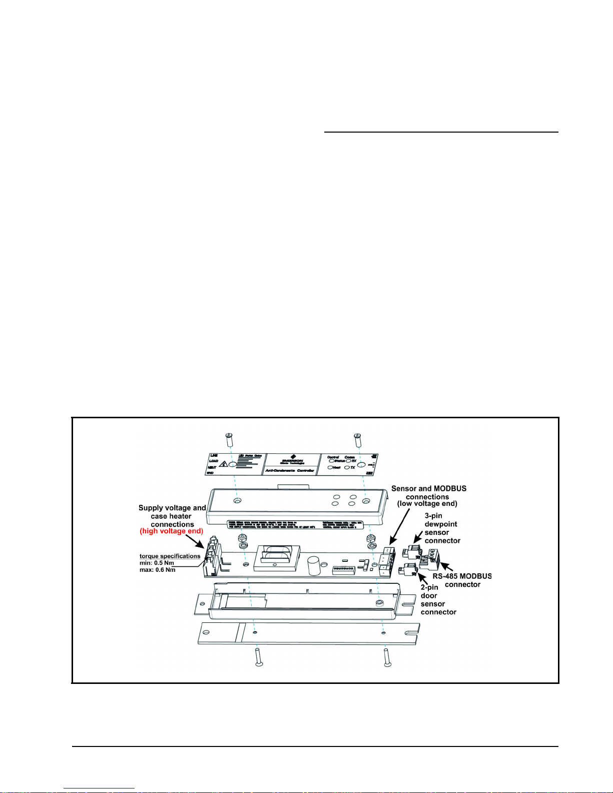
Figure 2-1 - Control Link ACC - Exploded View
Control Link ACC (P/Ns 815-6100 and 815-6105) Overview • 1
Page 8
2.2. Dewpoint Sensor
2.3. Door Frame
(P/N 814-6115)
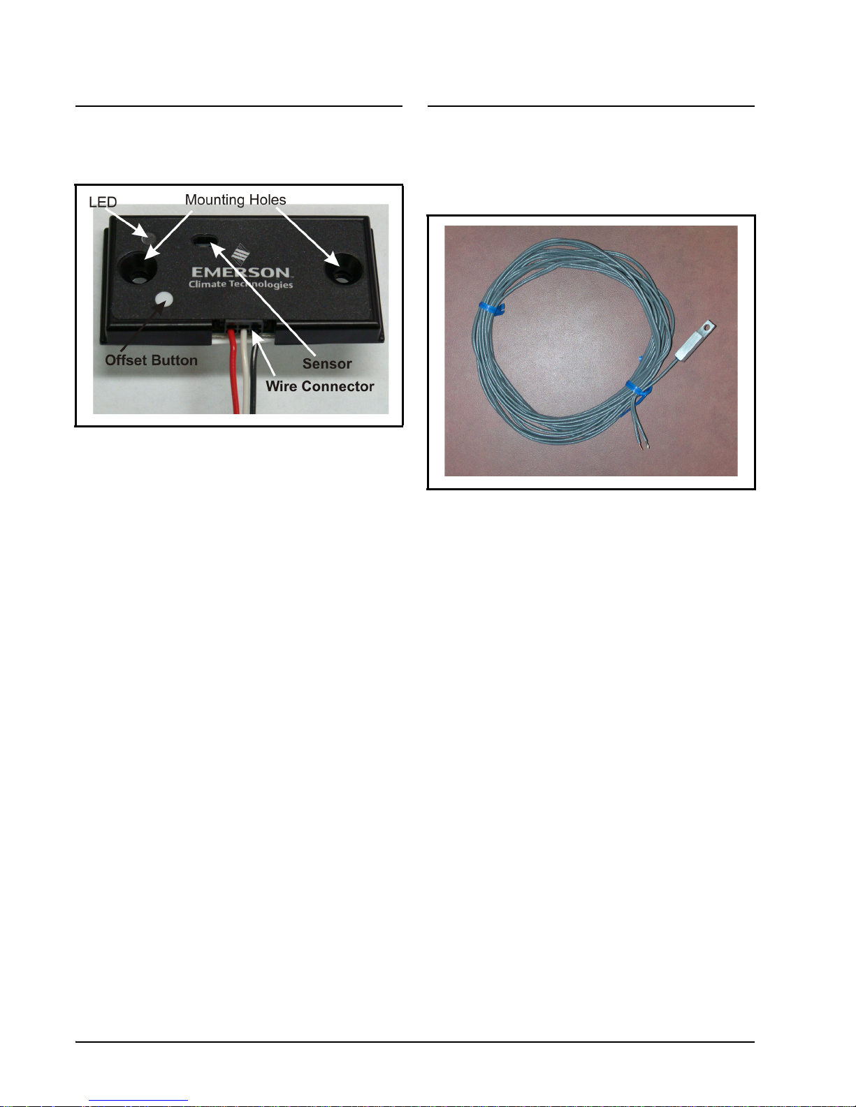
Figure 2-2 - Dewpoint Sensor (814-6115)
The Control Link ACC uses an external dewpoint
sensor (Figure 2-2) to measure the dewpoint of the
outside air next to the case doors. This sensor is
typically mounted directly above or to the side of the
case doors.
The dewpoint sensor is supplied in a mountable
enclosure with a 3-pin connector that attaches the
Control Link ACC to the dewpoint sensor (use a
3-wire 22AWG cable harness - Belden# 8771
P/N 135-8771 not supplied). The push button will
increase the offset in 1-degree (Celsius) (1.8°F)
increments indicated by the LED.
When Control Link ACC controllers are networked together via MODBUS, a single dewpoint
sensor connected to one Control Link ACC may be
shared by multiple Control Link ACC controllers.
Temperature Sensor
(P/N 281-0002)
Figure 2-3 - Door Frame Temp Sensor (281-0002)
In addition to the indoor air dewpoint, the Control
Link ACC also factors in the value of the temperature
of the case door frame using a mounted temperature
sensor (Figure 2-3). The door frame temperature
sensor should be mounted to the coldest surface of the
door frame. The door frame temperature sensor is
supplied with a 16-foot (4.88-meter) two-wire cable,
which plugs into the matching 2-pin connector on the
bottom, low voltage end of the Control Link ACC
(side closest to the LEDs).
2 • Control Link ACC I&O Manual 026-4704 Rev 6
Page 9
3 Mounting the Control Link ACC
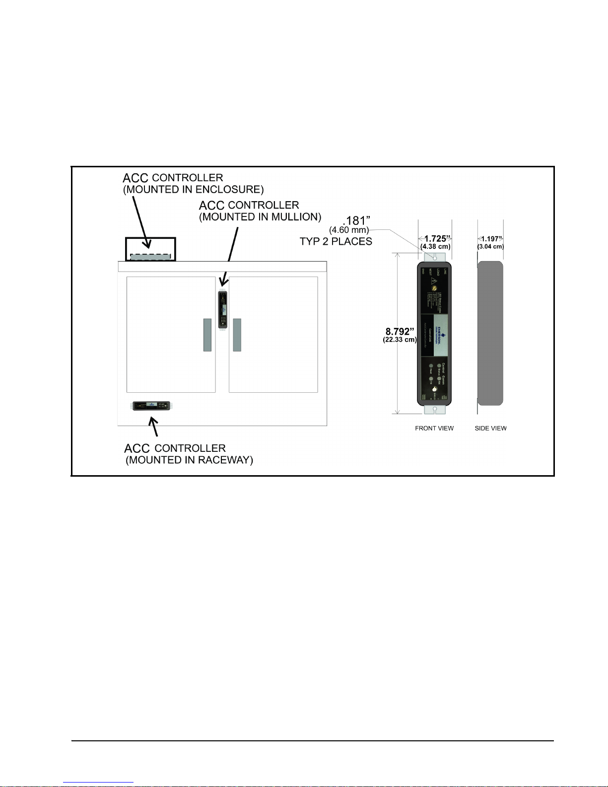
The Control Link ACC is designed to be mounted in a case mullion, but may also be mounted in the raceway
or in a metal electrical enclosure on the top of the case. Figure 3-1 shows examples of where the Control Link
ACC may be mounted.
Figure 3-1 - Control Link ACC Mounting
Use the two mounting tabs at the top and bottom of the enclosure to screw the enclosure to the case wall,
raceway, or enclosure.
Use 9/64” (3.57 mm) drill pilot holes for mounting, and secure the Control Link ACC to the metal surface
using #8-32 thread forming screws. Mounting screws are not included with the Control Link ACC.
For heater current greater than 10A, the Control Link ACC UL Recognized version with external heat sink
must be used (P/N 815-6105). The heat sink of the Control Link ACC must be securely mounted against a
large heat-conductive surface. Using thermal grease, the Control Link ACC has a metal back which acts as a
heat sink, dissipating heat from the Triac that controls the heater.
The metal must be mounted against a conductive metal surface so heat can be conducted out of the
controller. Failure to secure against the case mullion or other metal surface may cause controller overheating
and shutdown.
Door Frame Temperature Sensor (P/N 281-0002) Mounting the Control Link ACC • 3
Page 10
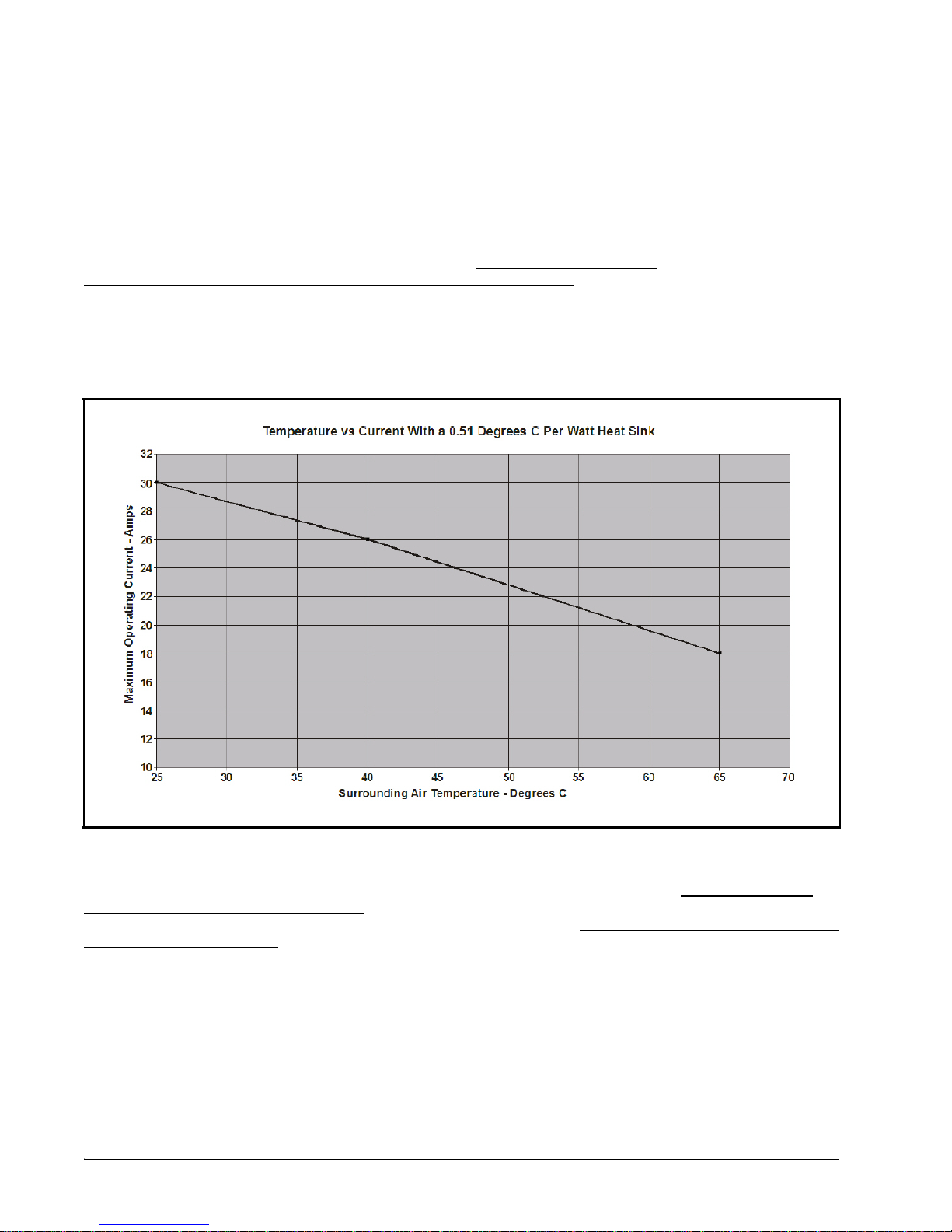
4 Calculating Maximum Ambient
Temperature
Figure 4-1 shows the effects of adding an external heat sink with a 0.51°C/Watt (0.92°F/Watt) rating (using
thermal grease to ensure optimum thermal conductivity). Note that the 0.51°C/Watt
(0.92°F/Watt) heat sink rating is characteristic of typical case mullions.
An external heat sink is required for heater currents (greater than) > 10Amps.
To calculate the maximum ambient temperature at which the ACC should run with an additional external
heat sink, choose a current-amperage rating that will be operating for the case (y-axis) and plot the maximum
allowed operating temperature (x-axis) on the graph. For example, with an external heat sink at 26Amps, the
maximum ambient temperature would be 40°C (149°F).
Figure 4-1 - Ambient Temperature Calculation - additional heat sink
For heater current greater than 10A, the heat sink of the Control Link ACC must be securely mounted
against a large heat-conductive surface. Using thermal grease, the Control Link ACC has a metal back which
acts as a heat sink, dissipating heat from the Triac that controls the heater. The metal must be mounted against
a conductive metal surface so heat can be conducted out of the controller. Failure to secure against the case
mullion or other metal surface may cause controller overheating and shutdown.
4 • Control Link ACC I&O Manual 026-4704 Rev 6
Page 11

Figure 4-2 - Ambient Temperature Calculation - no external heat sink
Door Frame Temperature Sensor (P/N 281-0002) Calculating Maximum Ambient Temperature • 5
Page 12
5 Wiring the
Control Link ACC
WARNING! CONNECT THE LINE
VOLTAGE ONLY TO THE HIGH VOLTAGE
END OF THE ACC, WHICH CONTAINS A
NON-REMOVABLE 4-TERMINAL BLOCK.
OTHERWISE, DAMAGE TO THE BOARD MAY
RESULT.
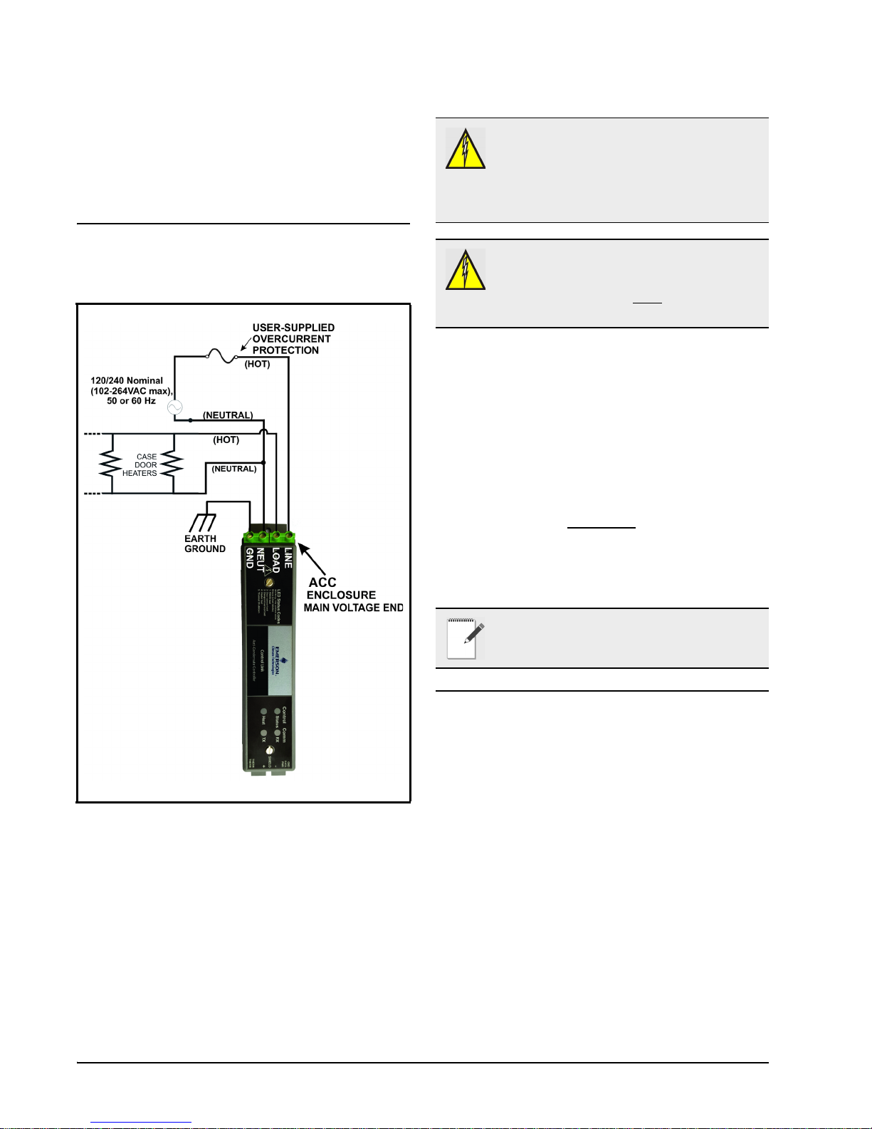
5.1. Power and Heater
Element Wiring
WARNING! OVER-CURRENT
PROTECTION OF THE LOAD MUST BE
DONE OUTSIDE OF THE CONTROL LINK
ACC. THE ACC DOES NOT
INTERNAL FUSING.
Connect the NEUT terminal to the NEUTRAL
side, and the LINE terminal to the HOT side of 120/
240 Nominal (102VAC to 264VAC), 50/60Hz line
voltage.
The LOAD terminal carries supply voltage when
the door heater Triac relay is ON (closed). Connect
the LOAD terminal and NEUTRAL side of the line
voltage to the case door heater elements. All heater
elements in the door frame and all doors of that frame
should be connected in parallel
ACC.
Connect the GND terminal on the controller to
Ground.
NOTE: For supply connectors, use 16AWG or
larger wires rated for at least 105 °C.
HAVE
to the Control Link
Figure 5-1 - Power/Heater Wiring
The screw connectors on the main voltage end of
the Control Link ACC enclosure are where the
connections to supply voltage and the case door
heater element(s) are made.
6 • Control Link ACC I&O Manual 026-4704 Rev 6
5.2. Ratings and Current
Protection
The Control Link ACC (P/N 815-6100) is UL
Listed for up to 10A max (40°C) and 7A max (65°C).
The Control Link ACC (P/N 815-6105) is UL
Recognized, with external heat sink, for up to 30A
max (25°C), up to 26A max (40°C), and up to 18A
max (65°C).
Page 13
6 Mounting and Wiring the Sensors
6.1. The Dewpoint Sensor
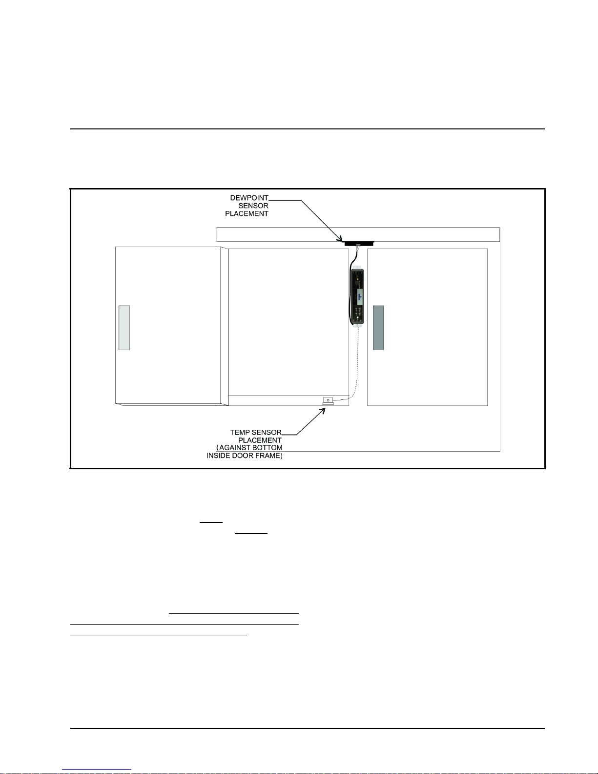
6.1.1. Placement
Figure 6-1 - Sensor Placement
In order for the Control Link ACC to function
properly, the dewpoint sensor must
it can measure the dewpoint of the air outside
case. Mount the sensor underneath the top side of the
case in the area just above the top of the doors
(Figure 6-1).
A 0.25” x 0.25” (6.35 mm x 6.35 mm) notch in the
edge of the metal frame behind the sensor may be requi re d f or the wi re s conn ec ting the dewpoint sensor to
the Control Link ACC. DO NOT let any RTV sealants
touch the sensor element and keep the sensor element
as far as possible from RTV-sealed areas.
Do NOT mount the dewpoint sensor near the
bottom of the case or any place where cold air from
the case can affect the sensor reading. Avoid
mounting the sensor in an area with excessive water
spray or moisture, extremely dirty environments, near
The Dewpoint Sensor Mounting and Wiring the Sensors • 7
be placed where
the
heat sources, or in the direct path of HVAC returns.
Secure the sensor to the mounting location with the
two included screws (P/N 031-6005) as shown in
Figure 6-2. Emerson recommends using pilot holes
for the screws. Tighten the screws just enough to
secure the sensor without warping the sensor housing.
Page 14

6.1.2. Note About Using RTV
Sealants
6.1.3. Dewpoint Sensor Mounting
Dimensions
Placing the dewpoint sensor in either of these
locations may require a hole to be drilled in the case
to run the wire from the sensor to the Control Link
ACC. Use caution when sealing this hole with RTV
sealants — the sensor element is sensitive to high
concentrations of RTV. Do not let any RTV sealants
touch the sensor element, and keep the sensor element
as far as possible from where the hole is sealed.
The dewpoint sensor’s mounting holes have 2.35”
(5.97 cm) spacing. Choose a location as close to the
case doors as possible, preferably directly over the
doors or (if necessary) on top of the case. Secure the
sensor to the mounting location with the two screws
provided. Note that the enclosure allows clearance for
a nut driver on the screw head. Figure 6-2 shows the
mounting dimensions.
Figure 6-2 - Dewpoint Sensor Dimensions
It may be necessary to cut a 0.25” x 0.25”(6.35 mm x 6.35 mm) notch in the edge of the metal frame behind
the sensor for the wires to pass through.
6.1.4. Dewpoint Sensor Wiring
The dewpoint sensor cable can be 20-24 AWG range. Emerson recommends Belden# 8771 (P/N 135-8771)
22AWG cable or equivalent (not supplied). To install or remove wires from the dewpoint sensor connector,
insert a small screwdriver, such as a Phoenix Contact (P/N 011-6993) PTSM Screwdriver (not supplied), into
the top rectangular slots on the connector (above the wire terminals) until it stops; insert or remove wires as
shown in Figure 6-4. Insert the three wires on the other end of the cable to the matching 3-pin connector of the
low voltage end of Control Link ACC by pressing in the orange tabs above the terminals using the small
screwdriver. Ensure the wire colors match for the Power, Data and Ground terminals on Dewpoint Sensor and
the Control Link ACC.
8 • Control Link ACC I&O Manual 026-4704 Rev 6
Page 15

Figure 6-3 - Dewpoint Sensor Wiring
ACC
LOW VOLTAGE END
3-pin connector
2-pin
connector
TEMP
SENSOR
CABLE
BLACK
RED
WHITE
GND
PWR
DATA
THERM
THERM
Figure 6-4 - Dewpoint Sensor Connector - ACC View
The Dewpoint Sensor Mounting and Wiring the Sensors • 9
Page 16

6.1.5. Dewpoint Sensor Storage
Prior to installation, dewpoint sensors should be
stored separately from the cables. Do not store cables
and sensors together for a long period of time in a
closed box or bag. The sensor should be separated
from the cables when a shipment is received and
stored apart, preferably exposed to room air. The
sensors can become contaminated by outgassing from
the cable insulation if kept in a closed up box or bag
with the cable. Contamination can be reversed with
exposure to room air over a period of weeks or in a
temperature/humidity chamber over a period of three
days.
NOTE: If replacing the dewpoint sensor,
replace the entire assembly (keep the existing
cable).
6.2. The Door Frame
Temperature Sensor
6.2.1. Placement
The door frame temperature sensor should be
placed in an area where it can measure the
temperature of the door frame in the location on the
door frame that stays the coldest. The coldest spot on
a door frame is usually the bottom horizontal section
of the stationary frame, under the center door (for
cases with even-numbered doors), or near the center
mullion (for cases with odd-numbered doors). Cooler
doors may also be coldest at the top center of the
frame. Figure 6-1 on page 7 shows an example of
placement in a case with even-numbered doors — the
sensor is placed under the door just to the left of the
center mullion where the Control Link ACC is
installed. Do not mount the sensor outside the case
mullion - mount the sensor inside the case mullion.
Mount the case door frame temperature sensor
along the door frame inside the frame. Secure the
sensor in place by screwing it to the door frame using
the mounting hole.
The sensor is supplied with a 16-foot (4.88-meter)
cable. Connect the sensor into the 2-pin connector
(labeled THERM) at the bottom (closest to the
LEDs), low-voltage end of the Control Link ACC.
10 • Control Link ACC I&O Manual 026-4704 Rev 6
Page 17

7 Network Wiring and Configuration
E2 PIB COM PORT ASSOCIATIONS
COM1
COM4
COM6
COM2
Serial Device
RS485 COM Port
(2 Connectors)
RS485 COM Card
(2 Connectors)
Serial Device
RS232 Port
POWER INTERFACE BOARD
(PIB)
E2 Modem/Expansion
COM Card Mounted
Above PIB
Plug-In
Modem
Card
COM3
E2 Enclosure (Right Side)
RS485
RS232
If each Control Link ACC will be configured with
its own dewpoint sensor, it is not necessary to network
the Control Link ACC together. However, when
networked, multiple Control Link ACC controllers
may use a single dewpoint sensor. Furthermore,
because the Control Link ACC is a MODBUScompliant device, a site controller can be
programmed to communicate with the Control Link
ACC controllers via MODBUS, supporting remote
configuration and data acquisition.
The E2 controller supports networking of up to 63
Control Link ACC controllers.
7.1. Network Connection to
E2
COM4 and COM6, which are optional ports requiring
expansion cards). COM ports can only be used for one
function; in other words, if COM2 is set up as the I/O
network, you cannot connect MODBUS devices to
COM2. Ensure your E2 is equipped with an RS485
COM Card (P/N 637-4890) and configured in E2
General Services (
, Serial tab) to
enable COM4 or an E2 Expansion COM Card
(P/N 637-4871) to enable COM6.
Connect the MODBUS network cable to the threeterminal connector on the COM port you wish to
assign as MODBUS. Like other Control Link
connections, wire RS485+ to RS485+, RS485- to
RS485-, and the shield cable to the middle term inal. If
the E2 will be the first device in the daisy-chain, set
the port’s termination jumpers to the TERMINATED
& BIASED position (all three jumpers UP);
otherwise, set all jumpers DOWN if not the first
device.
7.2. E2 Setup of Control Link
ACC Devices
Figure 7-1 - Location of E2 COM Ports
requires the E2 to be version 2.71 or above. Contact
Emerson for upgrade information if the controller is a
version before 2.71.
assigned for MODBUS communication (COM2, an
RS485 port on the E2 power interface board, and
Connecting a Control Link ACC to an E2 unit
An E2 has up to three COM ports that can be
7.2.1. Setup Network Ports
Before setting up a Control Link ACC, the port on
the E2 that has the MODBUS cable connected must
be set up as a MODBUS port.
1. Log in to the E2 with Level 4 access.
2. Press
3. Press
followed by - General
Controller Info.
+ to open the Serial tab of the General
Network Connection to E2 Network Wiring and Configuration • 11
Page 18

Controller Info setup screens:
and Controllers.
Figure 7-2 - Serial Communications Manager Screen
4. This screen will have a “Connection” field for all
COM ports on the E2. Highlight the COM port
connection field that will be used for Control Link,
and press - LOOK UP. From the list of
network types, select MODBUS.
5. Four fields will become visible underneath the
COM port connection field, which pertain to the
way the device communicates:
• Baud - Default setting is 19.2k. The baud rate
setting should be set to match the baud rate dip
switch settings of all Control Link devices. (All
devices connected to the same COM port should be
set to the same baud rate.)
• Data Size - Leave this field at the default value (8).
• Parity - Leave this field at the default value (None).
• Stop Bits - Leave this field at the default value (1).
6. Press
to save changes and exit.
7.2.2. Add and Connect Control Link
ACCs - E2 Firmware Revision
Prior to 2.8
Figure 7-3 - Connected I/O Screen
3. In the Connected I/O screen, in a section labeled
ECT Devices. Enter the number of ACC devices in
the CtrlLink ACC number field.
4. Press
5. Locate the CtrlLink ACC units you added to the
to return to the Network Setup menu,
then select
network list (press
list). The default name for a Control Link ACC
begins with a two-letter designator of the model
type (AC for anti-condensate). If desired, enter a
new name for each device in the Name field.
- Controller Setup.
and to scroll through the
To enable communications between E2 and the
Control Link units, the devices must be added and
addressed in E2.
1. Log in to the E2 with Level 4 access.
2. Press
12 • Control Link ACC I&O Manual 026-4704 Rev 6
- Connected I/O Boards
Figure 7-4 - Controller Setup Screen
6. By default, each CtrlLink ACC in the network list
has a board number of 0. To set the address and
begin communication, press
Select Address. In the list of MODBUS devices,
choose the address number corresponding to the
and select -
Page 19

Control Link ACC’s dip switch/jumper setting, and
to select it. If a network ID has already
press
been selected, its name will be shown next to the
network ID in this list. If the network ID you are
trying to assign has already been used, you must set
the network ID dip switch/jumper on this device to
a different number that is not being used.
the Control Link ACC having a firmware version
older than the minimum revision required by E2 for
communication. Replace the Control Link ACC
with a new controller that has the latest version of
firmware on it.
Figure 7-6 - Online Status Screen
Figure 7-5 - List of MODBUS Devices
7. Repeat Steps 5 and 6 until each Control Link ACC
device has a name and address.
8. When finished, press
Setup menu, then press
7-6). Locate the Control Link ACCs you set up, and
look at each device’s status in the Status field. You
will see one of the following messages:
• Online - The Control Link ACC is communicating
normally.
• Offline - The Control Link ACC is not
communicating, has not been commissioned, is not
functional, or is not powered up. Verify the Control
Link ACC is powered up, wired correctly, and has
the proper network address, baud rate, and parity
(see Section 11, Troubleshooting Control Link
ACCs and the ECT MODBUS Network).
• Unknown - The Control Link ACC is not
communicating or has not been commissioned.
Verify the Control Link ACC is powered up, wired
correctly, and has the proper network address, baud
rate, and parity (see Section 11, Troubleshooting
Control Link ACCs and the ECT MODBUS
Network).
• No Port - No port is set up in the E2 Serial
Configuration Manager to be a MODBUS port.
Follow the instructions in Section 7.2.1., Setup
Network Ports on page 11).
• Wrong FW Rev - This message is likely caused by
t o return to the Network
- Online Status (Figure
7.2.3. Add and Connect Control Link
ACCs - E2 Firmware Version
2.8 and above
To enable communications between E2 and the
Control Link units, the devices must be added and
addressed in E2.
1. Log in to the E2 with Level 4 access.
2. Press
Figure 7-7 - Connected I/O Screen
3. In the Connected I/O screen, under the ECT tab,
- Connected I/O Boards
and Controllers.
E2 Setup of Control Link ACC Devices Network Wiring and Configuration • 13
Page 20

Enter the number of ACC devices in the CtrlLink
ACC number field.
4. Press
5. Locate the CtrlLink ACC units you added to the
Figure 7-8 - Network Summary Screen
6. By default, each CtrlLink ACC’s board number in
to return to the Network Setup menu,
then select
network list (press
list). The default name for a Control Link ACC
begins with a two-letter designator of the model
type (CL for ControlLink) and a three-letter
designator for ACC (anti-condensate controller).
the network list is indicated by a - (dash). To set the
address and begin communication, press
Commission. (If you have more than one MODBUS
network, specify which network you want the
device to belong to.) A screen will open that will
allow you set the address:
- Network Summary.
and to scroll through the
to
Figure 7-9 - Set the Address of the ACC
7. In the list of MODBUS devices, choose the address
number corresponding to the Control Link ACC’s
dip switch/jumper setting, and press
it. If a network ID has already been selected, its
name will be shown next to the network ID in this
list. If the network ID you are trying to assign has
already been used, you must set the network ID dip
switch/jumper on this device to a different number
that is not being used.
to select
14 • Control Link ACC I&O Manual 026-4704 Rev 6
Figure 7-10 -
8. Repeat Steps 5 and 6 until each Control Link ACC
9. When finished, press
List of MODBUS Devices
device has been commissioned.
t o return to the Network
Setup menu, then press
(Figure 7-8). Locate the Control Link ACCs you set
up, and look at each device’s status in the Status
- Network Summary
Page 21

field. You will see one of the following messages:
• Online - The Control Link ACC is communicating
normally.
• Offline - The Control Link ACC is not
communicating, has not been commissioned, is not
functional, or is not powered up. Verify the Control
Link ACC is powered up, wired correctly, and has
the proper network address, baud rate, and parity
(see Section 11, Troubleshooting Control Link
ACCs and the ECT MODBUS Network).
• Unknown - The Control Link ACC is not
communicating or has not been commissioned.
Verify the Control Link ACC is powered up, wired
correctly, and has the proper network address, baud
rate, and parity (see Section 11, Troubleshooting
Control Link ACCs and the ECT MODBUS
Network).
• No Port - No port is set up in the E2 Serial
Configuration Manager to be a MODBUS port.
Follow the instructions in Section 7.2.1., Setup
Network Ports on page 11).
• Wrong FW Rev - This message is likely caused by
the Control Link ACC having a firmware version
older than the minimum revision required by E2 for
communication. Replace the Control Link ACC
with a new controller that has the latest version of
firmware on it.
7.3. Wiring Types
Emerson specifies Belden #8761 shielded twisted
pair cables for use as MODBUS wiring (or Belden
#82761 and Belden #88761 for plenum installations).
If the recommended cable is not available in your
area, be sure the wiring meets or exceeds the
following specs:
Shielded? Yes
Conductor Type Twisted Pair
Gauge 18 - 24 AWG
Capacitance
between signal
wires
Capacitance between signal and
shield
Maximum Length 4000 ft/18 to 22 AWG
Nominal
Impedance
31 pF/ft or less
(9.45 m) or less
59 pF/ft or less
(17.98 m) or less
(1219.2 m)
2500 ft/24 AWG
(762 m)
12050
Figure 7-11 - Network Summary Screen
Wiring Types Network Wiring and Configuration • 15
Page 22

ACC
Te rm i n at i o n
Block
ACC
(bare wires) to 0V or
SHIELD terminal
S
H
I
E
L
D
+
Tie SHIELD to Earth Ground
at each node. Keep additional
wire length < (less than)
6” (15.24 cm)
7.4.2. Step 2: Connect the MODBUS
7.4. MODBUS Network and
Network Cable
Daisy-Chaining
Figure 7-13 - Control Link ACC Network Connection
MODBUS network cable has two conductors plus
Figure 7-12 - Control Link ACC Daisy Chain
Control Link ACC must be networked in a single
open communications loop, or daisy chain. A daisy
chain connects all the Control Link ACCs together in
a single unbranched series, and requires termination
jumpers to be set on the controllers at either end of the
chain. No branching or “star configurations” are
allowed.
7.4.1. Step 1: Disconnect Power to
the Control Link ACC and Open
the ACC Enclosure
WARNING! DISCONNECT THE SUPPLY
POWER FROM THE CONTROL LINK ACC
BEFORE OPENING THE ENCLOSURE.
OPENING THE ENCLOSURE WHILE THE
CONTROL LINK ACC IS POWERED MAY RESULT
IN ELECTROCUTION.
Connecting a Control Link ACC to a MODBUS
network requires you to remove the top cover from
the Control Link ACC enclosure. Press down the tab
at the main voltage end of the enclosure, and remove
front cover of the Control Link ACC. If the Control
Link ACC is already mounted in the case mullion,
you may have difficulty removing the front cover; if
so, loosen the top mounting screw before pressing the
tab.
16 • Control Link ACC I&O Manual 026-4704 Rev 6
a shield. For each Control Link ACC, connect the two
conductors to the 485 terminals of the MODBUS
connector labeled + and - (at the bottom, low voltage
end of the enclosure), making sure to use the same
wire colors for each Control Link ACC connection.
For example, if the conductor wire colors are BLACK
and WHITE, use BLACK for all 485+ terminals and
WHITE for all 485- terminals (or vice-versa).
Connect the bare (SHIELD) wire to the center Shield
terminal (0V terminal on the E2).
7.4.3. Step 3: Set the Network
Address
NOTE: If you are networking Control Link
ACC only for purposes of sharing a dewpoint
sensor, you do not need to set a network
address. Set all network address dip switches or
jumpers to the DOWN (OFF) position. This will allow
the Control Link ACC to share a dewpoint sensor as
long as the network is physically present and terminated
correctly. The network address is only necessary for
assigning a network ID for MODBUS applications.
Depending on the hardware revision, the Control
Link ACC board has either eight dip switches or eight
three-pin jumpers, located in between the controller
and network status LEDs. Switches or jumpers 1-6 set
the network ID for the controller. Switches 7 and 8 set
the network baud rate and parity.
Page 23

Each Control Link ACC that will use the MODBUS network must have a unique network ID. Number each
controller in sequence, starting with 1. Refer to Figure 7-14 for dip switch and jumper settings
Figure 7-14 - Control Link ACC Network ID Dip Switch/Jumper Settings
7.4.4. Step 4: Set the Network Baud Rate and MODBUS Parity
Figure 7-15 - Control Link ACC Network Baud Rate/Parity Dip Switch/Jumper
NOTE: If you are networking Control Link ACC only for purposes of sharing a dewpoint sensor, you do not
need to set a baud rate or parity. Set all dip switches or jumpers to the DOWN (OFF) position.
the Control Link ACC to share a dewpoint sensor as long as the network is physically present and terminated
correctly. The dip switches or jumpers are only necessary for assigning a network ID for MODBUS applica-
tions.
This will allow
MODBUS Network and Daisy-Chaining Network Wiring and Configuration • 17
Page 24

In order for the Control Link ACC to communi-
TB
END
OF
DAI
SY CHAI
N
FROM LAST
DEVICE
AT END OF
DAISY-CHAIN
SHIELD
WIRE
(CONNECT
TO EARTH
GROUND)
cate with each other on the MODBUS network, they
must all be set to communicate at the same baud rate
and parity.
Switch/jumper 7 determines the baud rate at which
the controllers communicate. When switch/jumper 7
is ON, the Control Link ACC will operate at 9600
baud. If switch/jumper 7 is OFF (default), the Control
Link ACC will operate at 19200 baud. Switch/jumper
8 determines the MODBUS network parity. Some
MODBUS-enabled site controllers require even
network parity; to enable even parity, set switch/
jumper 8 to the ON position. For site controllers that
require no parity, set switch/jumper 8 to the OFF
(default) position.
7.4.5. Step 5: Terminate the End
Devices
wired to the end of the cable segment using the threepin connector. Wire the two signal wires to the outside
terminals, and connect the shield to Earth Ground:
Figure 7-17 - MODBUS Termination Block
7.4.6. Step 6 - Connect a Dewpoint
Sensor to Control Link ACC(s)
on the Network
Figure 7-16 - Control Link ACC Network Termination
Once all Control Link ACCs are networked, you
must terminate the end devices on the network.
7.4.5.1. Termination Block Network
Because the Control Link ACC has no on-board
means of termination, use the MODBUS termination
block (P/N 535-2711) for termination that can be
Once the Control Link ACCs are networked and
properly terminated, the only step remaining to allow
the Control Link ACCs to share a dewpoint sensor is
to connect at least one dewpoint sensor to one Control
Link ACC on the network. Any Control Link ACC on
the network can be configured with the dewpoint
sensor.
Each Control Link ACC first looks for a dewpoint
sensor connected to itself. If a dewpoint sensor is
directly connected to a Control Link ACC, it will use
that sensor for its dewpoint value and broadcast the
sensor’s value on the MODBUS network. If no sensor
is directly connected to a Control Link ACC, it will
au tomatically look on the MODBUS network and use
the sensor value broadcast by another Control Link
ACC that has a sensor.
For fail-safe purposes, you may have multiple
dewpoint sensors connected to different Control Link
ACCs on the network. The Control Link ACCs
automatically select a primary sensor to use, and will
switch to another dewpoint sensor on the network if
the primary sensor fails or is disconnected.
For dewpoint sensor wiring instructions, refer to
Figure 6-3 and Figure 6-4.
18 • Control Link ACC I&O Manual 026-4704 Rev 6
Page 25

7.4.7. Step 7: Set the Setpoint
Temperature Offset
Figure 7-18 - Dewpoint Sensor Offset Button
The Control Link ACC seeks to maintain a
constant minimum difference between the dewpoint
of the outside air and the temperature of the door
frame. You may specify how big this difference will
be by pressing the temperature offset button on the
dewpoint sensor.
The offset button on the dewpoint sensor is located
on the lower left side of the sensor enclosure
(see Figure 7-18), and the offset value is indicated by
the LED in the upper left corner of the dewpoint
enclosure. The LED will normally flash once every 4
seconds.
1. Step 1: Push and hold the offset button for 5
seconds to enter the configuration mode. (The LED
will illuminate solid for 5 seconds prior to entering
configuration mode. After 5 seconds it will turn off
to indicate the dewpoint sensor has entered
configuration mode.)
2. Step 2: Release the offset button and the LED will
flash from 1 to 8 times depending on the current
offset configuration. Each LED flash represents a 1degree Celsius (1.8°F) incremental temperature
offset. If the button is not pushed any further, after
10 seconds the unit will exit the configuration mode
and will resume its normal operation and flash the
LED once every 4 seconds. (Repeat Step 1 to reenter the configuration mode.)
3. Step 3: If the button is pushed within 10 seconds
after the current setting is flashed, the offset value
will increment by 1 degree Celsius (1.8°F) and the
LED will flash the new offset value as one flash per
degree Celsius of offset. For example, if the offset
is set at 8°C (14.4°F), and the button is pushed to
increment the value, the value will start over at the
1-degree Celsius offset (1.8°F).
NOTE: If the offset button is pressed for more
than 15 seconds, the LED will remain ON solid
to indicate an offset button stuck condition, but
the offset value will not be changed.
The offset button determines the number of
degrees (in Celsius) that will be added to the value of
the dewpoint sensor to determine the target
temperature of the door frame. For example, if the
current dewpoint is 5°C (41°F) and the button is set to
a medium offset of 2°C (3.6°F), the Control Link
ACC will control the heaters to achieve a door frame
temperature of 7°C (44.6°F). As the dewpoint rises
and falls, the door frame temperature setpoint will
also rise and fall, so that the door frame temperature
will always stay slightly above the current dewpoint.
The Control Link ACC uses the offset button on
the dewpoint sensor to determine the value of the
temperature offset. The Control Link ACC prioritizes
them in the following ways:
1. If E2 is connected, the offset is configured at the E2.
2. If sharing a dewpoint sensor, the remote offset is
provided even if the Control Link ACC has its own
dewpoint sensor.
3. The local dewpoint sensor’s offset is used.
This priority structure is designed to make it easier
for temperature offsets to be changed in the field (by
simply changing it on the dewpoint sensor), and it
also allows multiple cases to use the same sensor
while using different temperature offsets.
TIP: Experiment with offsets to find the
lowest possible setting that still offers good
performance. In many cases, depending on
the placement of the door frame temperature
sensor, a LOW offset will still provide good anticondensate performance. The lower the offset being
used, the higher the energy savings.
7.4.8. Step 8 - Network
Configuration Is Complete Restore Power to the ACC
Restore power to the ACC and check the status of
the network by observing the LEDs on the front of
each Control Link ACC enclosure:
• If network communication is active, you should see
the RX LED blinking at least once every 15
seconds. If you see no activity or a regular blinking
pattern, there may be a problem with the MODBUS
MODBUS Network and Daisy-Chaining Network Wiring and Configuration • 19
Page 26

network wiring or configuration.
• For Control Link ACCs equipped with dewpoint
sensors, you should see the TX LED blink to
indicate transmission. If not, there may be a problem
with MODBUS or dewpoint sensor wiring.
• For Control Link ACCs that do not have dewpoint
sensors directly connected to them, verify the Status
LED is blinking once every 2 seconds to indicate
status is OK. If this LED blinks in a repeating
pattern of three short blinks, it means the Control
Link ACC is not receiving a dewpoint sensor value
broadcast over the network. There may be a problem
with the MODBUS or dewpoint sensor wiring.
20 • Control Link ACC I&O Manual 026-4704 Rev 6
Page 27

8 The ACC Hand-
1
4
3
2
5
6
7
8
10
9
11
12
13
14
LEGEND
Up Arrow
1
3
4
11
7
8
9
10
2
Power Switch
RS-485 Connector
Enter Key
LCD
Numeric keypad
Function Key F1
External Power Connector (9-12 VDC)
Period and Minus Keys
5
6
13
Function Key F2
Right Arrow
Down Arrow
Cancel Key
12
14
Left Arrow
Held Terminal
Interface
The RS-485 port supports the following:
• Standard dumb terminal mode protocol
• PL-430 version of I/O net
•I/O Net
•MODBUS
8.2. Keys and Functions
8.1. HHT Hardware
Overview
Key Functions
F1 Key Returns you to the Home Screen.
F2 Key Takes you to the Main Menu
Enter Saves your settings into the memory
Cancel Clears/Erases texts in the editable
field; cancels overrides
Left Arrow Selects the first editable field from
top of screen, and the next editable
field from top to bottom
Right Arrow Selects the last editable field starting
from the bottom of the screen; and
the previous editable field from
bottom to top
Down Arrow Moves to the next screen, editable
field, end of screen, or advances
Up Arrow Go back to previous screen, editable
field, or top of screen
Period Key Scroll list selections and scroll
Minus Key
Number Keys
(numbered 0-9)
through ASCII characters if in a text
field
Choose a menu option or enter a
value
Figure 8-1 - Hand-Held Terminal
The power switch determines the power mode of
the device, whether if self-powered (BATT), external
powered (EXT), or powered by a target device
(HOST).
The LCD screen can display up to 4 lines of
characters (each line can hold 16 characters). It
displays the home screen and the different menu
screens of the HHT. The LCD serves also as a visual
indicator that the HHT is functioning.
HHT Hardware Overview The ACC Hand-Held Terminal Interface • 21
Table 8-1 - HHT Keys and Functions
Page 28

8.3. Hand Held Terminal
ECT HHT: <S/W>
814 - 3112
(PRESS )
VER: 1.00F01-01
8.4. Connecting the HHT
Expansion Board
Figure 8-2 - Hand Held Terminal Expansion Board
With the 814-3112 Hand-Held Terminal and the
536-3120 Adapter Board, you can access the ACC via
its MODBUS communication port without having to
use the site controller. The Hand-Held Terminal
interface allows you to perform these general
functions:
• View failure messages that relate to the ACC
• View the status of inputs
• View the output percentage ON
• Override the outputs to a fixed percentage
• Make temporary or permanent changes to set points.
If also connected to a site controller, any changes
will be overwritten
An ACC HHT will also have these specific
functions:
• It can issue a command to switch the MODBUS port
into a dumb HHT port to view and set ACC
information like a standard HHT
• It can be used to update firmware for the attached
ACC
Adapter Board
The HHT Adapter Board is connected on the low
voltage end of the ACC using a standard Belden 8761
cable (shown in Figure 8-3). The Hand-Held
Terminal plugs into the RJ11 jack on the HHT
Adapter Board. Press the Hand-Held Terminal
connector into the jack until it snaps into place. When
the connector is correctly seated, and the HHT is
powered up in Battery or External Power Position the
user will see the Home screen of the HHT.
8.4.1. HHT Home Screen
If the ACC is connected to an E2 network, the
network connection needs to be removed.
22 • Control Link ACC I&O Manual 026-4704 Rev 6
Figure 8-3 - HHT Adaptor Board Connection to the ACC
Page 29

8.5. HHT Interface
CONTROL LINK ACC
815 - 6100
(PRESS )
VER: 1.00F01-01
SELECT
1= SLAVE TERMINAL
3= UPGRADE ACC FW
2= ACC HHT MODE
ACC SETUP
BAUD : 19200
ADDR : 1
PARITY : NONE
WAITING CONNECT
TO MASTER CNTRL
Navigation
The Hand-Held Terminal interface consists of a
simple series of screens and menus.
8.5.1. Scrolling Through The HandHeld Screens
The up arrow and down arrow keys are used to
scroll through the screens. Some of these screens are
read-only, others are either menus that require you to
enter a selection or are configuration screens that have
one or more editable fields. The right arrow and left
arrow are used to select editable fields.
8.5.2. Shortcut Keys (F1 and F2)
At any time, you may press the F1 key on the
Hand-Held Terminal to return to the Home Screen, or
F2 to view the first status screen.
8.5.3. ACC HHT Network Setup
When the ACC is connected to the HHT for the
first time using the HHT protocol, the Network Setup
menu will be displayed.
HHT ONE-ON-ONE connection type (no other
nodes connected to the network). See Section 8.5.8.
for details.
If setting the address via the dip switches, set the
address to match the dip switch numbering in the
HHT Network Setup Screen (ADDR: 1).
Selecting option 2 (ACC HHT MODE) will lead
you to the Network Setup screen.
The network screen will display the baud rate, address, and parity selection. A baud rate of 19200 is
recommended, set the parity to NONE, and choose
the address of the ACC unit you need to access. A
message will then appear:
SLAVE TERMINAL: Returns the HHT into a mode
controlled by the host.
ACC HHT MODE: Enter the mode where the
MODBUS port runs the standard HHT dumb terminal
protocol.
UPGRADE ACC FW: Upgrade the firmware of an
ACC to the version loaded on the HHT.
NOTE: Press F1 for approximately 6 seconds
to return to this screen at any time.
8.5.3.1. Modes of ACC Addressing
The ACC can be addressed in two different ways,
via the dip switch on the unit or by using the HHT to
set the address over MODBUS. If you are setting the
address with the HHT, all the dip switches must be set
to 0 or OF F, a nd you must be d irectly conne cted to t he
Once you are in the ACC HHT mode, it will
display the ACC home screen (see Section 8.5.4.).
To leave ACC HHT mode to access another ACC,
press F1 for approximately 6 seconds. You will see
the Home Screen for the HHT shown at the start of
Section 8.4.
8.5.4. The ACC HHT Interface
8.5.4.1. ACC Start Screens
After finishing the initial setup, the HHT display
will show the model type, the part number, and the
firmware revision.
The fourth line of the home screen will flash and
display failure information if the HHT detects an
internal or communication problem after its powerup. If more than one failure exists, information will be
displayed according to the following priority order:
• FAIL: FLASH/CLK: The flash memory on the
HHT Interface Navigation The ACC Hand-Held Terminal Interface • 23
Page 30

micro is corrupted, and/or the crystal clock is not
DOOR TMP: 12.6
DOOR STPT: 13.0
TMP: 75 RH: 50
ROOM DP: 32.0
DUTY CYCLE%: 34
OVR: NO %: 00
SAVINGS%: 62
OVR SRC: HHT
functioning properly
• FAIL: DEWPT SNS: The ACC does not have a
valid dewpoint sensor reading.
• FAIL: TEMP SNS: The door frame temp sensor is
not functioning properly.
• FAIL: OVER TEMP: The output heater is turned
off because the driver is overheating.
OVR SRC: Source of the current override (HHT or
REMOTE).
NOTE: The HHT will be able to override an
override that was initiated remotely. The user
will be able to override the heater output to a
fixed percentage. Once the HHT is removed,
the override will end.
8.5.5. ACC Status Screens
The two ACC Status Screens show the current
readings of all ACC inputs, the Relative Humidity, the
Ambient Temperature, the Dewpoint and the Door
Temperature, and other operating information.
8.5.5.1. Input Status Screen
DOOR TMP: The current value from the door frame
temperature sensor. The statuses OPEN or SHORT
mean the sensor is not functioning properly.
DOOR STPT: The current value of the door frame
temperature setpoint.
ROOM DP: The current value of the room dewpoint
sensor. NONE means the ACC has not received a
valid dewpoint reading.
TMP: The current value of the ambient temperature.
NONE means the ACC has not received an ambient
temperature reading. The ACC bases control on the
dewpoint sensor so this is not critical.
RH: The relative humidity. NONE means the ACC
has not received a relative humidity reading. The
ACC bases control on the dewpoint sensor so this is
not critical.
SAVINGS%: The percentage of time the heater has
been off. This field may be reset by selecting it and
pressing cancel.
8.5.6. ACC Configuration Screens
All of the configuration of the ACC may be
changed using the HHT. HHT users may change
setpoints and overrides.
8.5.6.1. HHT Changes When ACC is
Connected to E2
All changes to setpoints made by the HHT are
temporary if the ACC is connected to a parent E2.
Changes made in the HHT do not change the
configuration stored in the E2. When the HHT is
unplugged from the ACC, all changes made by the
HHT are overwritten by the E2, including output
overrides. If you wish to make permanent changes to
the ACC’s configuration, you must make them
through the E2 (or through a remote communication
program connected to the E2, such as UltraSite32).
8.5.6.2. HHT Changes When ACC is
Stand-Alone
If the ACC is operating standalone with no
connection to an E2, the HHT is the only method that
may be used to change configuration. When the HHT
is unplugged from the ACC, all changes to
configuration will be saved. Overrides made with the
HHT, however, will be canceled when the HHT is
unplugged.
8.5.5.2. Output Status Screen
DUTY CYCLE%: The current output condition.
OVR and %: Active heater output override (YES or
NO) and percentage.
24 • Control Link ACC I&O Manual 026-4704 Rev 6
Page 31

8.5.6.3. The Main Selection Screen
SELECT:___1
1: NETWORK
3: CTRL OPTIONS
2: TEMP OFFSET
ACC SETUP
BAUD : 19200
ADDR : 1
PARITY : NONE
DEW POINT SENSOR
STATE: ONLINE
VER: 1.00FO1
CONTROL LOOP:
MODE: CLOSED
BoardTemp: 77.3
OFFSET SRC: REM
ACT OFFSET: 1.0
CYCLE TIME: 0
PRG OFFSET: 2.0
100%DewPT: 65
0%DewPT: 25
CYCLE TIME: 10
Press down arrow past the Status Screen to access
the Main Selection screen. To select, press the right
arrow key, enter the number of the sub-menu you
wish to access, then press down arrow key twice to
access the sub-menu’s first screen.
• Network - General info about the ACC network and
dewpoint sensor attached.
• Temperature Offset - Setpoints that determine the
operation of the ACC.
• Ctrl Options - Where PID parameters are selected
8.5.6.3.1. Network
The network screen will display the baud rate,
address, and parity selection.
Board temperature will shutdown the output
heater if greater than 212°F (100°C)
Two modes can be selected for the temperature
offset, Closed Loop, and Open Loop.
Closed Loop
Closed Loop is the default that uses the Door
Temperature feedback.
OFFSET SRC: Specifies the source of the set point
offset:
• REM - Remote means it takes the offset reported
over ModBus network.
• PRG - Program means it uses the offset configured
as part of the user configuration.
• LOC - Local means it uses the offset set for the local
dew point sensor.
ACT OFFSET: Active temperature offset.
PRG OFFSET: Programmed temperature offset.
CYCLE TIME: Set from 0 to 30 seconds
(recommended setting). If the Cycle Time is 0 then
the controller will work in an instantaneous mode
where the output is updated every 0.1 seconds. Leave
the value to 0 for the greatest energy savings.
If the dewpoint sensor is connected, a screen will
display the state (ONLINE or OFFLINE) and the
firmware version of the sensor.
8.5.6.3.2. Temperature Offset Screen
The source of the set point offset can be selected
on the temperature offset screen. The set point offset
is added to the dew point to determine the setpoint for
door temperature.
HHT Interface Navigation The ACC Hand-Held Terminal Interface • 25
Open Loop
100%DewPT: Temperature offset at 100%.
0%DewPT: Temperature offset at 0%.
CYCLE TIME: Set from 0 to 30 seconds. For an
Open Loop operation, 10 seconds is recommended.
Page 32

8.5.6.3.3. Control Options Screen
PI PARAMETERS
P: 2.0
TEMP: FAHRENHEIT
I: 0.10
SELECT
1= SLAVE TERMINAL
3= UPGRADE ACC FW
2= ACC HHT MODE
CONTROLLINK ACC
VER: 3.10B006
UPGRADE: NO
SLOT: 1 CNT: 0
ACC SETUP:
BAUD: 19200
ADDR: 1
PARITY: NONE
UPGRADE RESULT:
FIRMWARE UPDATED
ACC SETUP:
BAUD: 19200
ADDR: 1
PARITY: NONE
ONE-ON-ONE?
NEED TO SET NODE
PROCEED?: NO
BAUD AND PARITY.
If the upgrade was successful this screen will
display:
The PID Parameters have been set to default
values 2.00 and 0.10. These values should not need to
be changed.
TEMP: Used to set the HHT display option. All
temperatures are in degrees Celsius internally, but
when TEMP is set to Fahrenheit (default) they are
displayed as Fahrenheit.
8.5.7. Upgrading ACC Using HHT
Return to the main HHT screen by pressing F1 for
approximately 6 seconds (if you are talking to an
ACC and in the ACC mode)
Select 3 for upgrade firmware and a new screen
will appear:
Press the down arrow to go to the Menu screen.
8.5.8. Changing ACC Address Using
HHT
If you are setting the address of the ACC with the
HHT, you must be connected directly to one and only
one ACC. From the Home screen, choose 2 (ACC
HHT mode), choose the address, and press down
arrow. (The user can also set the baud and parity,
19200 and no parity is recommended)
Pressing the down arrow may show you the next
screen if the HHT doesn't find an ACC at that selected
address.
Use the right/left arrow to see the arrow appear
next to NO (default). Press the – (dash) button to
toggle to YES.
Select the address of the ACC to upgrade.
Press the down arrow to start the upgrade. The
Block number will update as blocks are sent to the
ACC.
26 • Control Link ACC I&O Manual 026-4704 Rev 6
The HHT will ask if you are connected to the ACC
that you wish to communicate with directly; the user
has to be connected directly to set the address of an
ACC. Press the left or right arrow keys to display the
arrow next to the NO (default). Press the - (dash) key
to toggle it to YES.
Once the address (and/or baud and parity) is
changed, you will be connected in ACC HHT mode
and you will see the ACC Home Screen. See Section
8.5.4. for more details.
NOTE: If the address is already pre-set on the
ACC using the dip switches, the address cannot
be changed with the HHT. The pre-set dip
switches on the ACC will always take priority.
Page 33

8.5.9. Exit HHT Mode
To exit a current mode on the HHT, unplug and
reconnect (cycle power) or press down the F1 key for
6 seconds. This will return you to the HHT home
screen where you can access the ACC-HHT Mode
option. Select the address of the ACC you wish to
access.
HHT Interface Navigation The ACC Hand-Held Terminal Interface • 27
Page 34

9 Operation
The Control Link ACC uses two algorithms for
modes of operation. For the standard mode of
operation, the Control Link ACC prevents moisture
accumulation by maintaining door frame temperature
based on the dewpoint and setpoint offset. The
alternate PMAC mode of operation can be configured
from the E2 and is also used under failure conditions
if no door frame temperature sensor is available.
Using the PMAC algorithm, the Control Link ACC
will calculate the heater ON time based on the
dewpoint temperature. The configuration has two
parameters: the first sets the lower dewpoint
temperature at which the heater will be OFF. The
second sets the upper dewpoint temperature at which
the heater will be 100% ON. A linear calculation is
made between those limits:
Heater ON% = 100%*(Current _Dewpt - DewptOFF)
(DewptON - DewptOFF)
The ACC monitors a board temperature near the
heater output driver to ensure that the heater driver
does not exceed its maximum temperature rating.
There is a back-off algorithm that will become active
once the monitored board temperature says the heater
driver is within 6°C (10.8°F) of the maximum
temperature rating. At 6°C (10.8°F) below the
maximum rating, the ACC will not let the heater
driver be ON more than 95% of the time. If the
temperature continues to rise and is within 3°C
(5.4°F) of the maximum rating of the heater driver,
the algorithm will not let the heater driver be ON
more then 90% of the time. The final step is triggered
if the heater driver is more than 2°C above its
maximum rating at which time the heater will be
turned OFF. This is the OVER TEMP failure
condition (see Section 10, Error Modes). Once the
heat driver temperature drops 5°C (9°F) it will be
allowed to come back ON.
This back-off strategy will only come into affect if
the heater has to be ON 100%, you are running at the
maximum rated current, you are at maximum rated
ambient for the ACC.
9.1. Control Link ACC Status
LEDs
Figure 9-1 - LED Locations
The Control Link ACC has four status LEDs that
indicate what the controller is doing. They are: the red
Heater Status LED (HEAT), the green General Status
LED (Status) and the two Network Status LEDs (red
transmit TX and yellow receive RX).
9.1.1. Heater Status LED
The Heater Status LED (Heat) glows red any time
the door heaters are ON, and is OFF when the heaters
are OFF.
Under normal operation, this LED should pulse
ON and OFF when no door sweat is visible, indicating
it is pulsing the heaters to maintain the necessary
amount of heat to prevent door sweating (given the
current dewpoint and case temperature). When a case
door is opened, the LED will remain ON for longer
periods of time (and may even remain ON without
pulsing) to compensate for the change in case door
frame temperature.
Note that it is possible for this LED to remain OFF
for long periods of time if the dewpoint is very low
(e.g., during dry winter days).
9.1.2. General Status LED
The General Status LED blinks green to indicate
the controller is powered up and functioning
normally, and whether or not there are any alarm
conditions.
If the controller is functioning normally, the
Status LED will blink once per second. If there is an
error condition, it will blink at different rates to
indicate the active error condition (see Section 10,
Error Modes).
28 • Control Link ACC I&O Manual 026-4704 Rev 6
Page 35

9.1.3. TX and RX Status LEDs
If the Control Link ACC is being networked with
other Control Link ACCs via its MODBUS network
connection, the TX and RX LEDs blink to indicate
transmission and receipt of network messages. On a
properly networked Control Link ACC, the RX LED
should blink about once every 15 seconds. If a
Control Link ACC has a dewpoint sensor, you should
also see the TX LED blink. If these LEDs do not
blink, there may be a problem with the MODBUS
network connection.
Control Link ACC Status LEDs Operation • 29
Page 36

10 Error Modes
The Control Link ACC has several error modes it
will enter when failures occur. The controller has a
General Status LED that blinks at a 0.5 Hz (1 blink
per second) rate if the microprocessor is running. If
any of the error modes below occur, the green Status
LED will blink at a rate specific to the error condition.
The controller has a Heat LED that illuminates when
the heater is on. In the case of an error condition, the
heater will go into the indicated mode. For each error
mode, note the priority level — if more than one error
mode is active, the LED blink rate will only show the
error condition with the highest priority (priority #1 is
the highest, and priority #5 is the lowest). Note that a
higher priority will mask a lower priority error until
the higher priority is fixed.
10.1.Priority 1: FAIL: OVER
TEMP
The board temperature sensor has determined that
the heater driver is exceeding its maximum
temperature rating. If this condition is detected, the
heater output will be turned OFF. Once the
temperature has fallen at least 5°C (9°F), the heater
will be allowed to come back ON. General Status
LED blinks 5 times: pause - 5 times - pause, and then
repeats.
10.3.Priority 3: FAIL: DEWPT
SNS
Cannot communicate with the dewpoint sensor,
and there is no dewpoint data being broadcast. The
ACC will attempt for a duration of 100 seconds to
communicate with a local dewpoint Sensor before
flagging this failure. Once past the first 100 seconds,
the remote timeout is 46 seconds before this error will
occur. If there is no dewpoint sensor, the heater will be
on 95% of the time. The General Status LED blinks 3
times: pause - 3 times - pause, and then repeats.
10.4.Priority 4: FAIL: FLASH/
CLK
Either the Flash executable code has changed or
the hardware clock is not functioning properly. The
General Status LED blinks: short - long - pause, and
then repeats.
10.5.Priority 5: FAIL:
CONFIGURE
The user configuration has an error in the version
stored in flash. The General Status LED blinks: long
- short -pause, and then repeats.
10.2.Priority 2: FAIL: TEMP
SENS
If the PMAC Algorithm mode is NOT enabled, a
door frame temperature sensor that is open or shorted
is considered to be a failure. The General Status LED
blinks 2 times: pause - 2 times - pause, and then
repeats. If the PMAC Algorithm is enabled, the
General Status LED will continue to blink normally
even if the door frame temperature sensor is not
present. If the door frame temperature sensor is not
present, the Control Link ACC will revert to PMAC
mode for operation.
30 • Control Link ACC I&O Manual 026-4704 Rev 6
Page 37

11 Troubleshooting
Control Link ACCs
and the ECT
MODBUS
Network
11.1.If Control Link ACC is
Offline
1. Check wiring - Verify the Control Link ACC is
properly connected to the MODBUS cable. Verify
the network polarity is correct (+ to +, - to -, 0V to
0V) and there are no loose wires. If none of the
Control Link ACCs are online, check wiring
connections on the E2. Check the cable jackets to
make sure all network cable is Belden #8761 or
equivalent.
6. Check network termination - The two devices on
either end of the MODBUS network should be
terminated, with all other devices in the daisy chain
unterminated. Check termination settings for all
devices on the network.
2. Verify MODBUS Port Setup - Press
E2 front panel. Verify COM2, COM4, or COM6 is
set up as a MODBUS port. If so, verify that the
MODBUS cable is connected to the proper
connectors (refer to Figure 7-1 on page 11). Verify
the COM port fields are properly set for ECT
MODBUS (19.2k baud, data size=8 bits,
Parity=NONE, stop bits=1).
3. Make sure Control Link ACCs were commissioned
- Press
followed by o n the E2 fron t
panel and verify the offline Control Link module
has a non-zero number in its Node/Board# field. If
the number in the Node/Board# field is zero (0),
highlight the controller name and select - SET
ADDRESS followed by
select the network ID that matches the setting on the
network address DIP switch/jumper.
4. Check Control Link ACC network card DIP
switch/jumper settings - make sure switches/
jumpers 1-6 on the Control Link ACC network card
match the network ID number of the offline Control
Link ACC.
5. Verify switches/jumpers 7 and 8 are in the DOWN
position - Switches/jumpers 7 and 8 in the DOWN
position specify 19.2k baud and no parity. If either
of these switches/jumpers are not in the DOWN
position, set them DOWN.
- Select Address. Then
+ on the
If Control Link ACC is Offline Troubleshooting Control Link ACCs and the ECT MODBUS Network • 31
Page 38

12 Specifications
Temperature Range Storage Temp: -40°C to 65°C (-40°F to 149°F)
Ambient Operating Temperatures
(UL Listed)
P/N 815-6100
Ambient Operating
Temperatures
(UL Recognized)
P/N 815-6105
Input Voltage 120/240 Nominal (102VAC to 264VAC) 50/60 Hz
Humidity 5% to 95% non-condensing
Door Frame Temp Sensor +/- 0.4°C of 0 to 80°C (+/- .72°F of 32°F to 176°F)
Dewpoint Sensor +/- 1°C (+/- 1.8°F) over RH of 40 to 95% RH
Agency Approvals UL916 Open Energy Management Equipment, File E118489, FCC Part 15
-40°C to +40°C (-40°F to 104°F)
up to 10A (indoor, freestanding with no additional heat sink)
-40°C to +65°C (-40°F to 149°F)
up to 7A (indoor, freestanding with no additional heat sink)
-40°C to +25°C (-40°F to 77°F) up to 30A (with additional heat sink with max
thermal resistance of 0.51°C/Watt (0.92°F/Watt)
-40°C to +40°C (-40°F to 104°F) up to 26A (with additional heat sink with
max thermal resistance of 0.51°C/Watt (0.92°F/Watt)
-40°C to +65°C (-40°F to 149°F) up to 18A (with additional heat sink with max
thermal resistance of 0.51°C/Watt (0.92°F/Watt)
up to +/- 0.6°C at -40°C and 120°C (+/- 1.08°F at -40°F and 248°F)
+/- 4°C (+/- 7.2°F) over RH of 10 to 40% RH
Class A (non-intentional radiators), CE, RoHS
Table 12-1 - Control Link ACC Specifications
32 • Control Link ACC I&O Manual 026-4704 Rev 6
Page 39

13 Part Numbers and Descriptions
Part Number Item Description
815-6100
815-6105
281-0002 Door Frame Temperature Sensor
814-6115 Dewpoint Sensor
281-0001 Door Frame Temperature Sensor (included with ACC Kits 1-4 listed below)
815-6101 ACC Kit (1) - Control Link ACC 10Amp and Door Frame Temp Sensor
815-6106 ACC Kit (2) - Control Link ACC 30Amp and Door Frame Temp Sensor
815-6102 ACC Kit (3) - Control Link ACC 10Amp, Door Frame Temp Sensor and
815-6107 ACC Kit (4) - Control Link ACC 30Amp, Door Frame Temp Sensor and
Table 13-1 - Control Link ACC Part Numbers and Descriptions
Control Link ACC 10Amp UL Listed
Control Link ACC 30Amp UL Recognized
Dewpoint Sensor
Dewpoint Sensor
If Control Link ACC is Offline Part Numbers and Descriptions • 33
Page 40

Page 41

Page 42

The contents of this publication are presented for informational purposes only and they are not to be construed as warranties or guarantees, express or implied, regarding the products or
services described herein or their use or applicability. Emerson Climate Technologies Retail Solutions, Inc. and/or its affiliates (collectively “Emerson”), reserves the right to modify the designs or
specifications of such products at any time without notice. Emerson does not assume responsibility for the selecti on, use or maintenance of any product. Responsibility for proper selection, use
and maintenance of any product remains solely with the purchaser and end-user.
026-4704 Emerson is a trademark of Emerson Electric Co. ©2019 Emerson Climate Technologies Retail Solutions, Inc. All rights reserved.
 Loading...