

Page 1

Controlinc Network Master
Model M250 Version 5.1
Installation and Operations Manual
MAN-01-09-91-0726-EN Rev. 1
May 2020
Page 2

Notes
May 2020
Installation and Operations Manual
MAN-01-09-91-0726-EN Rev. 1
This page intentionally left blank
Page 3

Installation and Operations Manual
MAN-01-09-91-0726-EN Rev. 1
Table of Contents
Section 1: Introduction
1.1 Reference Documents ................................................................................... 1
1.2 System Configuration ................................................................................... 2
1.3 General System Specifications ....................................................................... 4
1.3.1 Environmental .................................................................................... 4
1.3.2 Electrical ............................................................................................ 4
1.3.3 LCD Touch Panel Specifications ...........................................................4
1.3.4 M250 PLC Port 2 Setup for Database Exchange Link (DxL) ................... 5
1.4 Parts List ....................................................................................................... 8
Section 2: Installation
2.1 Network Master Mounting ............................................................................ 9
2.1.1 Mounting of NEMA Enclosure ............................................................. 9
2.1.2 Mounting of Rack Mount Enclosure ..................................................11
2.2 Power Input ................................................................................................ 12
2.3 Field Network Wiring .................................................................................. 12
2.3.1 Network Grounding ......................................................................... 13
2.3.2 Network Termination ....................................................................... 14
Table of Contents
May 2020
Section 3: Conguring the System
3.1 System Protection and Software Versions ................................................... 15
3.1.1 Password Protection ......................................................................... 15
3.1.2 CoProcessor Software Protection ..................................................... 15
3.1.3 Software Version Identification ........................................................15
3.2 Selecting Diagnostic/Programming Mode ................................................... 16
3.3 Chassis Identification and Hot Standby ........................................................ 16
3.4 Configuring Modbus Host Port Interface(s) ................................................. 16
3.4.1 Configuring Ethernet Ports ............................................................... 16
3.5 Configuring the Field Network .................................................................... 17
3.5.1 Configuring the Number of Slaves .................................................... 17
3.5.2 Configuring Field Network Baud Rate ............................................... 17
3.5.3 Configuring Network Master Receiver Time-Out ............................... 17
3.5.4 Configuring Report-By-Exception (RBE) ............................................ 17
3.6 Configuring Network Address Sequence ..................................................... 17
3.7 Configuring Device Types ............................................................................ 18
Table of Contents
i
Page 4

Table of Contents
May 2020
Section 4: Modbus Register Maps
Installation and Operations Manual
MAN-01-09-91-0726-EN Rev. 1
4.1 Valve Status and Command Registers per Modbus Function Code ............... 19
4.2 Valve Status Bit Data for Each Valve ............................................................. 20
4.2.1 Multiple Valve Status Locations Using Function Code 02 ...................21
4.2.2 Multiple Valve Status Data Using Modbus Function Code 03 ............. 22
4.2.3 Multiple Valve Status Data Using Modbus Function Code 04 ............. 22
4.3 Reading Valve Position and Setpoint ............................................................ 23
4.4 Writing Discrete Commands to Valve Actuators .......................................... 23
4.5 Writing Analog Valve Position Setpoint (Function Codes 06 and 16) ............ 24
4.6 Reading Auxiliary Analog Inputs Using Function Code 03 ............................ 24
4.6.1 Reading Torque Analog Input Using Function Code 03 ...................... 24
4.7 Reading and Writing Auxiliary Analog Outputs ............................................ 24
4.8 Reading User Discrete Inputs ....................................................................... 25
4.9 Writing User Relay Outputs (MRTU Support) ............................................... 25
4.10 System Status Word .................................................................................... 26
4.11 Combined System Alarms ........................................................................... 27
4.12 Network Fault Location ............................................................................... 27
4.13 M250 Global Database and Modbus Holding Register Map .......................... 27
Section 5: Theory of Operation
5.1 Valve Actuator Network Connections .......................................................... 31
5.2 Power-up Initialization .................................................................................31
5.3 Hot Standby Fail-Over .................................................................................32
5.3.1 Modbus Host Link and Fail-over ........................................................ 33
5.4 Network Fault Detection ............................................................................. 33
5.5 Polling Process ............................................................................................ 33
5.6 Report-by-Exception ...................................................................................34
5.7 Priority Scan ................................................................................................ 34
5.8 Writing Discrete Commands to Valve Actuators .......................................... 34
5.9 Writing Position Setpoint ............................................................................ 35
5.10 Writing Analog Outputs .............................................................................. 35
5.11 Writing User Relay Outputs ......................................................................... 35
5.12 Writing ESD Command ............................................................................... 35
Section 6: Software Source Code
6.1 Host Database Configuration Aid ................................................................ 36
ii
Table of Contents
Page 5

Installation and Operations Manual
MAN-01-09-91-0726-EN Rev. 1
Section 7: LCD Touch Panel Backup Terminal Operation
7.1 Home Screen ..............................................................................................37
7.1.1 Alarm Display ................................................................................... 38
7.1.2 Security Codes Screen ...................................................................... 38
7.1.3 ESD Screen ....................................................................................... 39
7.1.4 Switch Active Master to Standby Screen ........................................... 39
7.2 Valve Control and Status Display ................................................................. 40
7.2.1 Valve Control .................................................................................... 40
7.3 Navigation Buttons ..................................................................................... 41
7.4 Network Diagrams ...................................................................................... 42
7.5 Network Fault Location ............................................................................... 42
7.6 Alarm Display .............................................................................................. 43
Section 8: System Setup and Conguration Using LCD
Touch Panel
8.1 Main Menu Screen ....................................................................................... 44
8.2 Security Codes ............................................................................................ 45
8.3 Data Entry ................................................................................................... 45
8.4 Host Port Configuration .............................................................................. 46
8.5 System Setup .............................................................................................. 47
8.6 Scan List ...................................................................................................... 48
8.7 Device Type ................................................................................................. 49
Table of Contents
May 2020
Section 9: Valve Network Topology
9.1 E>Net Ring Network on NEMA BOX or Rack Mount ...................................... 50
9.2 Redundant Parallel Bus Networks ................................................................ 51
Section 10: Multiple Masters to DCS
10.1 Master’s can be Distributed Throughout the Plant .......................................52
10.2 Using Ethernet Host Interface ..................................................................... 53
10.3 Using one RS485 and one Ethernet Modbus TCP/IP Host ............................. 54
Table of Contents
iii
Page 6

Notes
May 2020
Installation and Operations Manual
MAN-01-09-91-0726-EN Rev. 1
This page intentionally left blank
Page 7

Installation and Operations Manual
MAN-01-09-91-0726-EN Rev. 1 May 2020
Section 1: Introduction
Section 1: Introduction
Emerson Controlinc Network Masters are the master of Emerson Controlinc valve actuator networks
with Modbus RTU protocol. The system provides network management, data concentration, and
protocol conversion, off-loading the host system of these tasks. This enhances overall system
performance and minimizes software development and system conguration tasks by the system
integrator. The Network Master serves as the master of a master/slave network. It manages the
network by keeping an orderly cycle of data transfers to and from the slave devices (valve actuators).
It handles error detection, alarming, and network recovery. The Network Master serves as a data
concentrator for the host by providing a common database for all slave devices. The host is required
to communicate with only one slave device (network master) for all data transfers to and from the
eld. Data can be transferred between the network master and host in large blocks at a much higher
communications rate than would be possible if the host communicated with each slave device
(valve actuator) on the eld network. The Network Master acquires data from the valve actuators by
polling or scanning each device in a sequence of slave address from a table called a scan list. Polling
is a process of the Network Master sending to each slave address, a command to return its status
information, including alarms, discrete and analog inputs and outputs. When control commands
(valve open, stop, close, position setpoint, etc.) are generated by a host system up-line of the
Network Master, it then sends the appropriate commands over the network to the addressed slave
device. A more detailed functional description of operation is provided in the Theory of Operation
section of this manual.
1.1 Reference Documents
In addition to this Controlinc Network Master Operations Manual, the following references are
required for proper installation, conguration, and operation of the Network Master. All referenced
documents are supplied with the system. Paragraph numbers, as listed below, are used for reference
to these documents in this manual.
1. Emerson Controlinc 320B Quick Start Guide
2. FACTS Engineering 205 Basic CoProcessor User's Manual
3. FACTS Extended BASIC Reference Manual
4. Direct Logic DL205 User Manual
5. Bettis XTE3000 Electric Actuator IOM
All manuals and software are provided in electronic format with the system on CD.
Introduction
1
Page 8

Section 1: Introduction
May 2020
1.2 System Conguration
Controlinc Network Master Model M250N contains redundant valve actuator network masters in a
single enclosure. M250N supports one Controlinc E>Net ring network with up to 250 valve actuators.
Options for support of redundant bus networks and redundant E>Net rings are also available. The
supplied system uses standard RS485 and Modbus RTU protocol for the valve actuator networks.
Ethernet TCP/IP encapsulated Modbus protocol connections are provided for redundant host
computer networks. The Ethernet links are IEEE 802.3 with RJ45 connectors for 10/100Base-TX.
Protocol is Ethernet v2 encapsulation TCP/IP Version 4.
Redundant systems consist of two identical chassis with identical software. One is the primary
master and the other a hot stand-by master. The two chassis may switch roles of primary and hot
stand-by at any time. Figure 1 shows the specic system conguration of the supplied system.
The network masters communicate with Controlinc valve actuators that control both block valves
(Open, Stop, Close) and modulating or positioner type valves. The system consists of two six-slot
chassis with each chassis having a central processor located in Slot 0, which provides a global
database for the CoProcessors installed the chassis. The central processor also performs such
functions as watchdog timers and system alarm generation for the CoProcessors. It also provides
interrupt control for fast data transfers between processor modules. The main processor in each
chassis supports a “Data Exchange Link” (DxL) to share all data between redundant databases. See
Figures 2 and 3 for internal communication link connections.
Each chassis consists of two Modbus Slave modules located in Slots 3 and 4. These slave modules
communicate with redundant Modbus host systems up line. The CoProcessor installed in Slot 1 is
the Controlinc Network Master to a ring eld network. Two ports of the Network Master module are
connected to Network Interface Module (NIM) Model M124I with redundant, isolated ports. Each
NIM has connections to the redundant Network Master modules of the redundant chassis. Any one of
the four ports may acquire data from and control all actuators in the eld in either direction around
the network. Multiple M250N systems may be networked from a single host or redundant hosts to
automate any size system from a few valves to thousands of valves covering a large network area.
Ten (10) independent processors ensure full redundancy of all functions in a single unit. All
components except display are redundant with double-redundant host links to redundant hosts
and automatic processor hot swapping. Host equipment is not required to implement any fail-over
logic. Full-time redundant Modbus host links are standard. Plug-in modular construction and DIN-rail
mounting of components ensure minimum MTR, minimizing down time. LCD touch panel provides
valve actuator monitor and control of all valves in case redundant host links fail. All valve status and
alarms may be displayed by the LCD touch panel for maintenance purposes. The LCD touch panel
is a valuable troubleshooting tool during system commissioning. A more detailed description of
operation is provided in the Theory of Operation section of this manual.
Installation and Operations Manual
MAN-01-09-91-0726-EN Rev. 1
2
Introduction
Page 9

Installation and Operations Manual
MAN-01-09-91-0726-EN Rev. 1 May 2020
Section 1: Introduction
Figure 1 DCS System Diagram
Ethernet Links
10/100 BaseT
RS232 Modbus RTU
Links at 115.2K baud
NEMA Enclosure
with LCD Touch Panel
Introduction
3
Page 10

Section 1: Introduction
May 2020
Installation and Operations Manual
1.3 General System Specications
1.3.1 Environmental
Storage temperature: –20 °C to 70 °C
Ambient operating temperature: 0 to 55 °C
Ambient humidity: 5 to 95% (non-condensing)
Vibration resistance: MIL STD 810C, Method 514.2
Shock resistance: MIL STD 810C, Method 516.2
1.3.2 Electrical
Standard input voltage: 117 V AC at 50/60 Hz (100-240 V AC)
Total current at nominal voltage: 3.5 A (includes LCD panel)
Maximum inrush current: 60 A
Total power consumption: 35 VA nominal (includes LCD)
Isolation resistance: >10 MΩ at 500 V DC
Dielectric withstand voltage: 1500 V AC at 1 min.
MAN-01-09-91-0726-EN Rev. 1
1.3.3 LCD Touch Panel Specications
— Display type: 5.7 in. diagonal color TFT
— Enclosure: NEMA 4/4X (IP65)
— Input voltage: 12–24 V DC
— Power consumption: 16.0 W, 1.30 A at 12 V DC, 0.66 A at 24 V DC
— Operating temp: 0 to 50 °C
4
Introduction
Page 11

Installation and Operations Manual
MAN-01-09-91-0726-EN Rev. 1 May 2020
Section 1: Introduction
1.3.4 M250 PLC Port 2 Setup for Database Exchange Link (DxL)
Primary Master Secondary Master
DirectNet DirectNet
Base Timeout x 1 Base Timeout x 1
RTS/CTS 0 mS, 0 mS RTS/CTS 0 mS, 0 mS
Station Address 2 Station Address 1
38400,1, Odd, Hex 38400, 1, Odd, Hex
PLC to PLC cable is RS232, 3-wire, rolled, with 15-pin D connectors
Primary Secondary
Pin/Wire Pin/Wire
2 Red 3 Red
3 Wht 2 Wht
7 Grn 7 Grn
8 Blk 8 Blk
Introduction
5
Page 12

Section 1: Introduction
May 2020
Figure 2 M250 NEMA TP Internal Wiring
Installation and Operations Manual
MAN-01-09-91-0726-EN Rev. 1
6
Introduction
Page 13

Installation and Operations Manual
MAN-01-09-91-0726-EN Rev. 1 May 2020
Section 1: Introduction
Figure 3
Introduction
7
Page 14

Section 1: Introduction
May 2020
1.4 Parts List
Figure 4 is a list of materials supplied within each Network Master enclosure. This may be used as a
spare parts list.
Figure 4
Installation and Operations Manual
MAN-01-09-91-0726-EN Rev. 1
Item Qty Model
1 1 EA9-T6CL-R 2000802501 Color graphics LCD touch panel
2 1 2938730 2001803004 Power Supply, 24 V DC, 3 A
3 1 NIM124I 84713 -C Network Interface Module, Iso. RS485
4 2 D2-06B-1 2001805050 Base, 6-slot with 110/220 V AC P/S
5 2 D2-250-1 2001805052 CPU, DL205-250
6 6 37586-1 Cable, CoProcessor to NIM, 6x6, 11”
7 8 F2-CP128 2001805051 CoProcessor, Overdrive
8 1 NIM-TCP 87065 Network Interface Module, Ethernet
9 1 37587-1 Cable, CPU to CPU DxL
10 3 BK/MDA-1 7019900428 Fuse, 1 A, 250 V, Time Lag, CRM MDA
11 2 37586-4 Cable, CoProcessor to LCD, 6x6, 15”
12 2 37586-3 Cable, CoProcessor to NIM, 6x6, 13”
13 2 37586-2 (NEMA) Cable, CoProcessor to LCD, 6x6, 46”
14 1 37587 (NEMA) Cable, CPU to CPU DxL
8
Emerson Part
Number
Description
Introduction
Page 15

Installation and Operations Manual
MAN-01-09-91-0726-EN Rev. 1 May 2020
Section 2: Installation
Section 2: Installation
2.1 Network Master Mounting
If the system is supplied from the factory in an NEMA enclosure, no internal wiring is required except
for connecting power and eld network wiring. The next three Sections (2.1, 2.2 and 2.3) discuss
mounting, power input and eld network wire connections to the NIM.
2.1.1 Mounting of NEMA Enclosure
The enclosure is rated for NAMA 4/12 and IP65/IP55. Dimensions of the enclosure are shown in
Figure 5. Mounting dimensions are shown in Figure 6. The enclosure may be bulkhead mounted
using the internal mounting holes. External mounting brackets may be used if desired.
When mounting using the internal mounting holes, caution must be used to ensure the holes are
sealed to maintain the NEMA/IP rating. The enclosure is supplied with ve 1/2" compression type
cable entry hubs. These may be tted with conduit type ttings if desired. If the system includes
backup LCD keypad terminal, some planning is required to allow for proper height above the oor to
view the display and properly operate the keypad.
Figure 5
Installation
(5) Cable entries are provided for:
(1) Power Cable
(2) Field RS-485 Network Cables
(2) Host RS-485 Network Cables
9
Page 16

Section 2: Installation
May 2020
NOTE
Allow 1 in. clearance on left side for ventilation and room for the door to swing open to left.
Figure 6 NEMA Box Mounting
Installation and Operations Manual
MAN-01-09-91-0726-EN Rev. 1
10
Installation
Page 17

Installation and Operations Manual
MAN-01-09-91-0726-EN Rev. 1 May 2020
Section 2: Installation
2.1.2 Mounting of Rack Mount Enclosure
The enclosure is designed for standard EIA 19" DIN rail rack mounting. Dimensions of the enclosure
are shown in Figure 7. The enclosure conforms to EIA RS-310, IEC 297-1, and DIN 41 494, Part 1
standards. The rack in which the enclosure(s) are mounted must allow a minimum of 20" (508 mm)
depth, allowing space for cable connections. If the system includes backup LCD keypad terminals,
some planning is required to allow for proper height above the oor to view the display and operate
the keypad properly.
Figure 7
Enclosure Depth = 15.0" (381 mm)
Allow a total depth of 20" (508 mm)
for rear panel cable connections.
Figure 8 Rear Panel View
Valve Network Ports
RJ45 Ethernet Ports
Installation
11
Page 18

Section 2: Installation
May 2020
2.2 Power Input
The system operates from 120 V AC or 220 V AC, 50/60 Hz single-phase power with internal
three wire power terminals. Ensure that a good safety ground is provided to the electrical supply to
which the power input is connected. The system contains three main fuses (6.3x32 mm, 1 A) in the
DIN-rail mounted fuse blocks. Each chassis and the LCD touch panel are independently fused. Each
NIM is powered from redundant 24 V DC power supplies from the two chassis power supplies. The
LCD touch panel is powered from an independent 24 V DC power supply. All other modules within the
unit are powered over the base back plane from the associated main chassis power supply.
2.3 Field Network Wiring
The eld network is wired in a ring conguration from Port A around a loop to Port B of the network
master. Beginning at Port A, the network is wired to Port A of the rst actuator and then from Port B of
the rst actuator to Port A of the second actuator and so on until the network returns from Port B of the
last actuator to Port B of the network master. Networks may have parallel wired (bus wired) actuators
between series wired actuators. Always wire parallel actuators to Port A and remove termination and
bias. Do not connect more than 15 actuators in parallel between any two series connected actuators.
Networks are polarized with (+) and (-) symbols on all drawings. Proper operation requires that polarity
be observed at all connections. Connect the eld networks to the Port A and B connectors on the NIM in
the network master as shown in Figure 9. The networks must be connected to Port A and Port B of the
valve actuators as shown in the wiring diagram of the Controlinc 320B Quick Start manual. Controlinc
supports many different network topologies. This manual supports only a single ring E>Net network
topology that allows a combination of parallel (bus) and series E>Net connections on the same network.
Installation and Operations Manual
MAN-01-09-91-0726-EN Rev. 1
12
Installation
Page 19

Installation and Operations Manual
MAN-01-09-91-0726-EN Rev. 1 May 2020
Section 2: Installation
Figure 9 Controlinc TEC2000 E > Net Ring Network Wiring (Typical)
2.3.1 Network Grounding
The shield or drain wire of the network must be earth grounded at only one point per network
segment. This single ground point may be at any location in the system where a good earth ground
can be obtained. This may be Port B of each actuator if desired. If the network shield is connected
to the internal ground or the chassis of the valve actuator, then the actuator housing must have
a good earth ground. The NIM connection is normally the building/vessel hull equipment ground
grid. A jumper may be installed between terminals 22 and 23 on the TBM of each actuator to carry
the ground throughout the loop. Do not connect the network cable shields to a power line ground
cable. Power lines can conduct lightning and other transients into the network. Do not connect both
ends of the network shield to earth ground at the network master. This can cause a ground loop,
making the transient protection system ineffective.
Installation
13
Page 20

Section 2: Installation
May 2020
2.3.2 Network Termination
The network requires termination and bias to be asserted at every network segment in
the E>Net ring. Parallel (bus) connected actuators must have termination and bias turned off.
Setting DIP switches S1 and S2 on the NIM to the ON position terminates the Network Master (NIM).
Figure 10 TEC2000 Controlinc E > Net Ring Network Wiring (Typical)
Installation and Operations Manual
MAN-01-09-91-0726-EN Rev. 1
14
Installation
Page 21

Installation and Operations Manual
MAN-01-09-91-0726-EN Rev. 1 May 2020
Section 3: Conguring the System
Section 3: Configuring the System
The system is shipped from the factory precongured per customer’s supplied data. This section
of the manual is provided only for conguration from a Modbus host port. The user should read
this entire section before attempting to congure the system. It may also be helpful to read Theory
of Operation Section 5 of this manual for a better understanding of the system before attempting
system conguration. Conguration data and associated Modbus registers are shown in Table 5-12
in Section 4 of this manual. The system is congured from any Modbus host capable of reading and
writing up to 540 conguration registers in the range of 42326 through 42866 shown in Table 5-12.
The system may be congured using the LCD touch panel. The system is congured at the factory per
the customer specications. If the user changes the total number of actuators on the eld network or
other operational parameters, then the system conguration must be changed. If the actuators are
not addressed in sequence around the loop, then the user must enter the actuator address sequence
in the Network Address Scan List. Other parameters such as Modbus port baud rate, network
master receiver time-out, and enabling/disabling diagnostic mode may be required during system
integration and start-up.
NOTICE
When conguration changes are made, the affected module will automatically reset and reinitialize
with the new conguration parameters. Caution must be used when conguring the Modbus
slave module to which the conguration computer is connected. The communication port of the
conguration computer must match the conguration written to the connected slave module. Both
primary and secondary chassis are congured at the same time regardless of which Module slave port is
used to congure the system.
3.1 System Protection and Software Versions
3.1.1 Password Protection
All software is protected by password available only to the programmer. The software development
package is not supplied with the system. Source code is supplied only for backup and must not be
modied by the user. Should a development software package be acquired, the software on the
system is password protected. This means the user may not edit the software without the password.
This does not limit the user’s ability to congure any part of the system via the Modbus host
communication ports.
3.1.2 CoProcessor Software Protection
Access to all application software in the CoProcessor modules is disabled unless each module is put
into diagnostic mode. The user must access the Modbus register containing the Diagnostic Mode
register by one of the Host communication links or the touch panel.
3.1.3 Software Version Identification
Software version number of each module may be obtained by reading the associated “Software
Version” Modbus register shown in Table 5-12. Software versions are reported as a three-digit
number with an implied decimal point between the rst and second most signicant digits.
Conguring the System
15
Page 22

Section 3: Conguring the System
May 2020
Installation and Operations Manual
MAN-01-09-91-0726-EN Rev. 1
3.2 Selecting Diagnostic/Programming Mode
The chassis near the bottom or back of the enclosure is the Primary chassis. The chassis near the
top or front of the enclosure is the Secondary chassis. Each chassis identies itself by setting the
appropriate bit in the “System Status Word”, Modbus Register 40254 as shown in Table 10 in
Section 4.10 of this manual. If Bit 8 is set, then the chassis with which you are communicating is the
Primary Network Master. If Bit 9 is set, then the chassis with which you are communicating is the
Secondary Network Master. Either chassis may be in Hot Stand-by mode. Bits 4 and 5 of register
40254 identify the chassis that is in hot standby. The two chassis may be forced to swap roles of
active and hot standby mode by writing a non-zero value to Modbus Register 40255. This register will
be reset to zero after mode swap is executed.
3.3 Chassis Identication and Hot Standby
The chassis near the bottom or back of the enclosure is the Primary chassis. The chassis near the
top or front of the enclosure is the Secondary chassis. Each chassis identies itself by setting the
appropriate bit in the “System Status Word," Modbus Register 40254 as shown in Table 10 in
Section 4.10 of this manual. If Bit 8 is set, then the chassis with which you are communicating is the
Primary Network Master. If Bit 9 is set, then the chassis with which you are communicating is the
Secondary Network Master. Either chassis may be in Hot Stand-by mode. Bits 4 and 5 of register
40254 identify the chassis that is in hot standby. The two chassis may be forced to swap roles of
active and hot standby mode by writing a non-zero value to Modbus Register 40255. This register will
be reset to zero after mode swap is executed.
3.4 Conguring Modbus Host Port Interface(s)
The host port may be congured for RS232 full duplex or RS422/RS485 with either 4-wire or 2-wire
half duplex by writing to the Port Hardware Mode register as shown in Table 12. The module must
be congured for RS232 if a NIM is used for connecting the Host RS-485 networks. Modbus slave
address, baud rate, and parity may be congured by writing to the associated conguration register
shown in Table 12.
3.4.1 Configuring Ethernet Ports
If your system is equipped with Ethernet host ports, the two ports for Host#1 and Host#2 must be
congured independently. Each port may be congured using Telnet or the supplied Device Installer
software. All network master parameters may be congured using Emerson Master Conguration
software. Setting of all Modbus coprocessor ports and the NIM-TCP ports must match, else
communication link will be lost. If no IP address was assigned at time of order, the default IP address
(169.254.132.147) labeled at each port on the NIM-TCP module may be used to access the ports and
assign an IP address. Both ports may be assigned the same IP address only when connected to two
independent Ethernet links. Software is supplied on the CD with the system to congure the system,
set IP addresses and test the system via the Ethernet ports.
16
Conguring the System
Page 23

Installation and Operations Manual
MAN-01-09-91-0726-EN Rev. 1 May 2020
Section 3: Conguring the System
3.5 Conguring the Field Network
Editing the values loaded to Modbus registers 42828 through 42833 as shown in Table 12
congure the eld network ports and network master functions. Each parameter is discussed in the
following paragraphs.
3.5.1 Configuring the Number of Slaves
The number of slaves (valve actuators) on the eld network is congured by editing the constant
loaded to “Number of Field Network Devices” in Modbus register 42830.
3.5.2 Configuring Field Network Baud Rate
Editing the constant written to Modbus register 42831 as shown in Table 5-12 change network baud
rate of the Network Master. If the number written to this register is not a valid baud rate, the system
will default to 9600 baud. The baud rate must match the baud rate of the valve actuators connected
to the network. The default baud of all devices and all ports of the Network Master is 9600.
3.5.3 Configuring Network Master Receiver Time-Out
Editing the constant loaded to Modbus register 42832 may change receiver time-out of the network
masters. Receiver time-out is the amount of time the network master will wait for a response from
a slave device before moving on to the next device. If this time is too short (less than 10 mS) it could
cause collisions on the network, degrading communications throughput. If this time is too long, it will
cause time to be wasted while the master is trying to put unconnected devices on the network. The
default setting is 50 mS.
3.5.4 Configuring Report-By-Exception (RBE)
Loading a zero to Modbus register 42833 will disable RBE. Writing a non-zero value to register 42833
enables RBE, the default setting.
3.6 Conguring Network Address Sequence
The network master must know the sequence of slave addresses around the network ring in order
to properly perform network fault location. Unless otherwise specied, all systems are shipped with
a scan list in contiguous sequence starting at address #1 at Port A and ending with the last address
at Port B. To change the sequence of addresses in the scan list, it is necessary to edit the scan list
located in Modbus registers 42326 through 42575 or the number of registers equal to the number
of actuators on the network. If the system reloads default settings, the contiguous sequence of 1 to
250 will be loaded to this list.
Conguring the System
17
Page 24

Section 3: Conguring the System
May 2020
3.7 Conguring Device Types
The network master must know the type of slave device connected to the network corresponding
to each network address in order to acquire the desired data. There are ve different device types
that may be selected for each unit connected to the network. All device types return valve status
(inputs 16-31). Remaining data acquired is listed below. For EHO extended status and alarms,
please use Device Type 4.
Device Data Acquired
Type 0 Valve position (0-100% in 1% increments)
Type 1 Valve position (0-100% in 1% increments)
Coils (0-15)
Inputs (0-15)
Type 2 Valve position (0-4095)
Position setpoint (0-4095)
Analog output (0-4095)
Type 3 Valve position (0-4095)
Position setpoint (0-4095)
Analog output (0-4095)
Coils (0-15)
Inputs (0-15)
Type 4 Valve position (0-4095)
Position setpoint (0-4095)
Analog output (0-4095)
Valve torque (0-4095)
User analog input #1 (0-4095)
User analog input #2 (0-4095)
Type 5 Valve position (0-4095)
Position setpoint (0-4095)
Analog output (0-4095)
Valve torque (0-4095)
User analog input #1 (0-4095)
User analog input #2 (0-4095)
Coils (0-15)
Inputs (0-15)
Type 7 XTE3000
Installation and Operations Manual
MAN-01-09-91-0726-EN Rev. 1
18
Unless otherwise specied, all systems are shipped with all devices congured as Type 2. To change
the device type for any one or all devices, it is necessary to edit the device type list located in Modbus
registers 42576 through 42825 or the number of registers equal to the number of devices on the
network. The touch panel may be used to edit device types. If the system reloads default settings, all
devices will be set as Device Type 2.
Conguring the System
Page 25

Installation and Operations Manual
MAN-01-09-91-0726-EN Rev. 1 May 2020
Section 4: Modbus Register Maps
Section 4: Modbus Register Maps
4.1 Valve Status and Command Registers per
Modbus Function Code
Controlinc Network Masters communicate with host computer equipment using Modbus RTU
protocol. Valve actuator status and alarms data may be acquired from the Network Master using any
one of four Modbus Function Codes (01 thru 04). Data is returned as either discrete (bit) type using
Function Code 01 and 02 or as 16-bit unsigned integers using Function Code 03 and 04. Command
outputs to the valves may be written to the Network Master using four Function Codes (05, 15, 06,
and 16). Table 5-12 is the address map for valve actuators up to a maximum of 250. Status of each
valve is stored as 16 discrete inputs and as 16 coils. Discrete commands to each valve consist of eight
bits (coils) per valve and are stored as coils in one 16-bit register per actuator. Position setpoint is an
analog word (0-4095) value written to the valve actuator using the 06 or 16 function codes.
All registers are unsigned 16-bit integers.
NOTE
Modbus addressing shown in the tables of this section is the normal conguration addressing method
used by most SCADA and DCS systems. If you are building Modbus messages at the communication
driver level, keep in mind that HEX-starting addresses in the Modbus message are offset by one. You
must subtract one from the address in the tables when building a Modbus message. For example, to
read the rst valve status bits as coils using Function Code 01, the starting address of 1025 shown in
Table 5-12 would be 400 Hex (1024 decimal) in the Modbus message. If valve status of the rst valve
is read using Function Code 02, the starting address of 10001 shown in Table 5-12 would be 00 Hex
in the Modbus message. If valve status of the rst valve is read using Function Code 03, the starting
address of 40001 shown in Table 5-12 would be 00 Hex in the Modbus message
Table 1. Memory Map of Valve Data and Commands by Function Code
Function Code and
Valve data/Command
01 Discrete valve status Read Coils (discrete) 01025 05024 4000
01 Discrete Outputs (0-15) Read Coils (discrete) 05089 09088 4000
02 Discrete valve status Read Inputs (discrete) 10001 14000 4000
02 Discrete Inputs (raw 0-15) Read Inputs (discrete) 14065 18064 4000
03 Valve status word Read Holding Register 40001 40250 250
03 Valve position feedback Read Holding Register 40256 40505 250
03 Valve position setpoint Read Holding Register 40576 40825 250
03 Aux. analog input #1 Read Holding Register 40826 41075 250
03 Aux. Analog input #2 Read Holding Resister 41076 41325 250
03 Aux. Analog output Read Holding Register 41326 41575 250
03 Discrete Inputs (raw 0-15) Read Holding Register 41576 41825 250
03 Discrete Outputs (0-15) Read Holding Register 41826 42075 250
03 Raw torque analog input Read Holding Register 42076 42325 250
04 Valve status word Read Input Register 30001 30250 250
04 Discrete Inputs (raw 0-15) Read Input Register 30256 30505 250
05 Discrete valve commands Write Coils (discrete) 00001 01000 1000
Command Data Type Begin Reg Ending Reg Max Number
Modbus Register Maps
19
Page 26

Section 4: Modbus Register Maps
May 2020
Installation and Operations Manual
MAN-01-09-91-0726-EN Rev. 1
Function Code and
Valve data/Command
05 Discrete Outputs (0-15) Write Coils (user relays) 05089 09088 4000
15 Discrete valve commands Write Multiple Coils 00001 01000 1000
15 Discrete Outputs (0-15) Write Multiple Coils 05089 09088 4000
06 Discrete valve commands Write Holding Register 40512 40575 64
06 Valve position setpoint Write Holding Register 40576 40825 250
06 Aux. analog output Write Holding Register 41326 41575 250
06 Discrete Outputs (0-15) Write Holding Register 41826 42075 250
16 Discrete valve commands Write Multiple Registers 40512 40575 250
16 Valve position setpoint Write Multiple Registers 40576 40825 250
16 Aux. Analog output Write Multiple Registers 41326 41575 250
16 Discrete Outputs (0-15) Write Multiple Registers 41826 42075 250
Command Data Type Begin Reg Ending Reg Max Number
4.2 Valve Status Bit Data for Each Valve
Valve status information is stored in contiguous registers in sequence with the valve actuator
network address. Table 2 shows the valve status for valve address #1 when using Modbus Function
Code 02.
Table 2. Valve Status Information for Valve at Network Address #1
Modbus Address Valve Status Description
10001 Open Limit Switch Valve Fully Open
10002 Close Limit Switch Valve Fully Closed
10003 Transition Opening Valve is Moving Open
10004 Transition Closing Valve is Moving Close
10005 Manual Mode Selector Swt in Local
10006 Auto Mode Selector Swt in Remote
10007 Open Torque Alarm Open Torque Swt Tripped
10008 Close Torque Alarm Close Torque Swt Tripped
10009 Valve Stall Alarm Valve is Not Moving
10010 Power Monitor Alarm Loss of Control Voltage
10011 Motor Overload Alarm Overload Relay Tripped
10012 Phase Monitor Alarm 3-Phase power reversed
10013 Local ESD Alarm Local ESD input activated
10014 Actuator Fail Alarm Failed self-diagnostics
10015 Com No-Response Alarm Com Failure on both lines
10016 Unit Alarm Set when any alarm bit set
Note: Unit alarm bit (10016) is set if any one or more alarm bits 7 through 13 are set.
20
Modbus Register Maps
Page 27

Installation and Operations Manual
MAN-01-09-91-0726-EN Rev. 1 May 2020
Section 4: Modbus Register Maps
For EHO extended status and alarms, please refer to Table 3.
Table 3. Valve Status Information for Valve at Network Address #1
Modbus Address Valve Status Description
10001 Off Mode Not in Local or Remote
10002
10003 Low Oil Level Low Oil Level
10004 Partial Stroke Fail Partial Stroke Fail
10005 Electronic Fault Alarm Electronic Failed Alarm
10006 Hydraulic Power Unit Fault Alarm Hydraulic Power Unit Fault Alarm
10007 Over Pressure Alarm Over Pressure Alarm
10008
10009
10010
10011
10012
10013
10014
10015
10016
4.2.1 Multiple Valve Status Locations Using Function Code 02
Valve status information shown in Table 3 is repeated for each actuator on the network in sequence
of network address. Data for valve at network address number 2 is located at Modbus addresses
10017 through 10032. Data for valve at network address 3 is located at 10033 through 10048 and so
on for up to 250 valves on the network as shown in Table 4.
Table 4. Using Modbus Function Code 02
Valve Actuator Network Address Modbus Addresses for Valve Status
001 10001 thru 10016
002 10017 thru 10032
003 10033 thru 10048
004 10049 thru 10064
005 10065 thru 10080
thru thru
248 13953 thru 13968
249 13969 thru 13984
250 13985 thru 14000
Modbus Register Maps
21
Page 28

Section 4: Modbus Register Maps
May 2020
Installation and Operations Manual
MAN-01-09-91-0726-EN Rev. 1
4.2.2 Multiple Valve Status Data Using Modbus Function Code 03
The same valve status data can be accessed by the Host using Function Code 03 by reading unsigned
16-bit integers from holding registers beginning at Modbus Address 40001 as shown in Table 5.
The 16 bits of valve status for each valve actuator is the same as that shown in Table 3.
Table 5. Using Modbus Function Code 03
Valve Actuator Network Address Modbus Addresses for Valve Status
001 40001
002 40002
003 40003
004 40004
005 40005
thru thru
248 40248
249 40249
250 40250
4.2.3 Multiple Valve Status Data Using Modbus Function Code 04
The same valve status data can be accessed by the Host using Function Code 04 by reading unsigned
16-bit integers from input registers beginning at Modbus Address 30001 as shown in Table 6. The 16
bits of valve status for each valve actuator is the same as that shown in Table 3.
Table 6. Using Modbus Function Code 04
Valve Actuator Network Address Modbus Addresses for Valve Status
001 30001
002 30002
003 30003
004 30004
005 30005
thru thru
248 30248
249 30249
250 30250
22
Modbus Register Maps
Page 29

Installation and Operations Manual
MAN-01-09-91-0726-EN Rev. 1 May 2020
Section 4: Modbus Register Maps
4.3 Reading Valve Position and Setpoint
Valve position feedback is accessed by the Host using Modbus Function Code 03 to read holding
registers beginning at Modbus address 40256. Position setpoint of each valve may be read in
sequence with valve address starting at Modbus address 40576. Device types 0 and 1 return valve
position as 0-100% in 1% increments. All other device types return analog data representing analog
position and setpoint of each valve as unsigned 16-bit integer with a 12-bit value of 0 to 4095. Each
valve's analog position and setpoint are located in holding registers in sequence of network address
as shown in Table 7.
Table 7. Valve Position Feedback and Setpoint using Modbus Function Code 03
Valve Actuator Network Address
001 40256 40576
002 40257 40577
003 40258 40578
004 40259 40579
005 40260 40580
thru thru
248 40503 40823
249 40504 40824
250 40505 40825
Position Setpoint
Modbus Addresses
4.4 Writing Discrete Commands to Valve Actuators
Discrete commands are written to a single valve actuator as coils (bit) data using Modbus Function
Code 05 or Function Code 15. Commands may also be written to multiple valve actuators by writing
a single holding register using Function Code 06 or to multiple holding registers using Function
Code 16. Emergency Shut Down to all valve actuators (ESD) is accomplished by writing seven (7) to
Modbus Register 40575. This will cause ESD to be broadcast to all valve actuator addresses. Writing
a zero to register 40575 ends the ESD function. Each valve actuator will respond to four commands
as shown in Table 8. The four bits associated with each valve is in sequence with the valve actuator
network address. When writing to holding registers, data is written to four valve actuators. Writing
zeros to any location has no affect on operation. Each command is a positive one (set coil) and the
coil is automatically reset when the command is executed. Only one coil per valve may be written at
any one time. Writing multiple coils to a single valve will cause no action, i.e. it is treated as a no-op.
Modbus Register Maps
Table 8. Writing Commands to Valves using Function Code 05 or 15
Modbus Address Comman and Valve Network Address
0001 Open - Valve at address 001
0002 Stop - Valve at address 001
0003 Close - Valve at address 001
0004 ESD - Valve at address 001
0005 Open - Valve at address 002
0006 Stop - Valve at address 002
0007 Close - Valve at address 002
0008 ESD - Valve at address 002
0009 Open - Valve at address 003
00010 Stop - Valve at address 003
00011 Close - Valve at address 003
00012 ESD - Valve at address 003
00013 Open - Valve at address 004
00014 Stop - Valve at address 004
00015 Close - Valve at address 004
00016 ESD - Valve at address 004
23
Page 30

Section 4: Modbus Register Maps
May 2020
Discrete command holding registers contain four commands per valve for four valves per 16-bit
register. A single register may be written to command four valves by using the Modbus Function
Code 06. Multiple registers may be written using Function Code 16. Command holding registers
begin at Modbus address 40512. A total of 63 registers are used for the command coils. The last valve
network address in register 40574 is valve address 250. Each actuator is congured to respond to the
ESD command in either of three ways; go closed, go open, or stay put. Each actuator can also control
an ESD relay, which may be wired to control the actuator, external equipment or to override some
internal function. See Section 1.1 for instructions on setting ESD functions of the valve actuator.
Installation and Operations Manual
MAN-01-09-91-0726-EN Rev. 1
4.5 Writing Analog Valve Position Setpoint
(Function Codes 06 and 16)
If the valve is a modulating or positioning unit (except device types 0 and 1), the position setpoint may be
written to the valve as an unsigned 16-bit integer from 0 to 4095 using Modbus Function Codes 06 or 16.
Setpoint of each valve is in sequence with network address. Any Emerson actuator with Controlinc, except
device types 0 and 1, may be a positioner or modulating unit. The actuator, depending on the command
issued by the master, automatically sets the operating mode.
4.6 Reading Auxiliary Analog Inputs Using
Function Code 03
Device types 4 and 5 have two auxiliary analog inputs for data acquisition of other equipment such
as pressure or temperature transducers. The two inputs for each actuator are identied as AIN2 and
AIN3. The analog data is returned as unscaled 12-bit unsigned integers with a value between 0 and
4095. The host is required to scale the values to engineering units for display to the Man Machine
Interface (MMI). The values are scaled by (real time value/4095*full scale engineering units). Data for
auxiliary analog inputs AIN2 is in sequence with network address starting at Modbus register 40826.
Up to 250 values may be acquired. The last register for the 250th unit is 42075. Data for auxiliary
analog inputs AIN3 is in sequence with network address starting at address 42076. Up to 250 values
may be acquired. The last register for the 250th unit is 42325.
4.6.1 Reading Torque Analog Input Using Function Code 03
Device types 4 and 5 may have an optional analog input for relative torque measurement. The torque
data is scaled as 0-4095 for 0-100% of the analog value read from register 15 labeled AIN#1. The user
must provide scaling at the host for conversion to actual torque based on the actuator model and
spring pack. Torque data range is provided on the data sheet supplied with each actuator. Torque
data may be used for detection of valve problems by measuring and storing an initial maximum
opening torque and then comparing the current reading to the stored initial maximum torque
reading. If the current reading exceeds the initial maximum torque reading by a predetermined
amount (limit), then a valve maintenance alarm or message may be generated. The analog torque
reading is in sequence with network address starting at Modbus register 42076. Up to 250 values
may be acquired. The last register for the 250th unit is 42325.
4.7 Reading and Writing Auxiliary Analog Outputs
All device types, except type 0 and 1, have an option to add one 4 - 20 mA analog output. The host
may write to the output by writing to a Modbus register in sequence with network address starting at
register 41326. Up to 250 analog outputs may be written. The last register for the 250th unit is 41575.
Data must be written to the actuators as 12-bit analog data with a range of 0 to 4095 corresponding
to 4 - 20 mA. The data is written to the actuators using Modbus Function Code 06 or 16. The analog
output may be read back from the actuator using Function Code 03
24
.
Modbus Register Maps
Page 31

Installation and Operations Manual
MAN-01-09-91-0726-EN Rev. 1 May 2020
Section 4: Modbus Register Maps
4.8 Reading User Discrete Inputs
Each Controlinc equipped actuator has two isolated discrete inputs available to the User. These are
Inputs 13 (User Input #1) and 14 (User Input #2) in the discrete input memory map. Inputs 0-15 are
the raw hardware discrete inputs and are de-bounced by software. None of the inputs are software
generated. The Network Master reads all discrete inputs (0-15) of device types 1, 3, and 5 and places
these into contiguous data base locations corresponding to network address of the actuator. Inputs
of each actuator are shown in Table 8. The host, using Function Codes 02, 03, and 04, may access
these inputs. When using Function Code 02, the inputs are addressed from 14065 to 18064 with
16 inputs per actuator as shown in Table 5-9 for up to 250 actuators. When using Function Code 03,
the discrete inputs are addressed from register 41576 (valve #1) to 41825 (valve #250). When using
Function Code 04, the discrete inputs are addressed from register 30256 (valve #1) to 30505
(valve #250). Inputs (bits) of each valve actuator within the 40000 and 30000 registers are in the
same sequence as shown in Table 9
Table 9. Discrete Inputs for Valve at Network Address #1 Using Function Code 02
Modbus Address Valve Status Description
10001 Open Limit Switch Valve Fully Open
10002 Close Limit Switch Valve Fully Closed
10003 Auxiliary Open Contact Aux. contact of starter
10004 Auxiliary Close Contact Aux. contact of starter
10005 Manual Mode Selector Swt in Local
10006 Auto Mode Selector Swt in Remote
10007 Open Torque Alarm Open Torque Swt Tripped
10008 Close Torque Alarm Close Torque Swt Tripped
10009 Power Monitor Alarm Loss of Control Voltage
10010 Motor Overload Alarm Overload Relay Tripped
10011 Phase Monitor Alarm 3-Phase power reversed
10012 Local ESD Alarm Local ESD input activated
10013 VFC Fault Alarm VFC alarm input activated
10014 User Discrete Input #1 Isolated user wired input
10015 User Discrete Input #2 Isolated user wired input
10016 On-board execute button Used by 320A or B only
.
4.9 Writing User Relay Outputs (MRTU Support)
Device types 1, 3, and 5 have two User Relay Outputs, which may be controlled by the host. The
outputs are Coils 04 (User Relay #1) and 05 (User Relay #2) in the Controlinc Coil Map (0-15). The
Network Master may read and write all 16 coils but masks all coils except 00, 01, 04 and 05. If the user
attempts to write to any other coils, the command will be ignored. The user should not write to coils
00 (close) or 01 (open) if the device is a valve actuator. Write these coils only if the device is an MRTU.
The database of the Network Master is congured for 16 coils per actuator for 250 actuators in
sequence with valve address. The User Relays may be controlled using Function Codes 05, 15, 06,
or 16. If Function Codes 05 or 15 are used the coils are addressed from coil 05089 to 09088 with
16 coils per actuator. For example, writing to the relays of valve number one, write to coil 05093 for
User Relay #1 and 05094 for User Relay #2. User Relays of each consecutive valve are offset by 16.
For example, User Relay #1 of valve number two would be coil 05109 (5093+16). Coils 00 (close)
and 01 (open) are masked by the network master when the selector switch is in "Remote" mode.
This prevents the host from overwriting these coils in the valve actuator when under control by the
Controlinc card in the actuator.
Modbus Register Maps
25
Page 32

Section 4: Modbus Register Maps
May 2020
4.10 System Status Word
The system status word is the status of the Network Master. This word is located in Modbus register
40254. The system status word may be read using Modbus Function Code 02 or 03 in the same
manor as reading valve status. Bit locations for Function Code 02 are shown in Table 10. Only the rst
least signicant twelve bits are dened.
The four most signicant bits are reserved for future functions and are set to zeros. If Bit 8 is set (true)
then the chassis is the primary network master. If Bit 9 is set (true) then the chassis is the secondary
network master. Bit assignments are shown in Table 10.
Table 10. System Status Word Bit Map
Bit Status Denition Note CR FC02
0 Primary Watchdog Timer Alarm 20 14049
1 Secondary Watchdog Timer Alarm 21 14050
2 Primary Failed Write Command Alarm C(FW) 22 14051
3 Secondary Failed Write Command Alarm C(FW) 23 14052
4 Primary Master in Hot Standby Mode C(HM) 24 14053
5 Secondary Master in Hot Standby Mode C(HM) 25 14054
6 Primary Network Fault Alarm C(NF) 26 14055
7 Secondary Network Fault Alarm C(NF) 27 14056
8 Primary Network Master Active C(AM) 30 14057
9 Secondary Network Master Active C(AM) 31 14058
10 Primary Host Link Failed Alarm 32 14059
11 Secondary Host Link Failed Alarm 33 14060
12 DXL Grant primary master access to network 34 14061
13 DXL Grant secondary master access to network 35 14062
14 DXL Fail Alarm 36 14063
15 Switch Active Master to Hot Standby & Standby to Active 37 14064
Installation and Operations Manual
MAN-01-09-91-0726-EN Rev. 1
Primary and Secondary Host Link Failed alarms shown in Table 5-10 are determined by queries
received from the Modbus host computer (DCS) using function codes 01, 02, 03, 04 or 08. If a query
is not received from the host in about ve to six seconds, then this alarm is set. Host link alarms are
exchanged between the primary and secondary network masters. These alarms are also used to help
determine which master takes control of the network.
The host communication status and associated network fail over is discussed in the Theory of
Operation Section of this manual. The host(s) must repeatedly transmit queries to both primary
and secondary masters within ve seconds between transmissions to prevent the masters from
detecting a faulty link from the host(s). The network master will not respond to any queries while in
hot standby.
26
Modbus Register Maps
Page 33

Installation and Operations Manual
MAN-01-09-91-0726-EN Rev. 1 May 2020
Section 4: Modbus Register Maps
4.11 Combined System Alarms
In addition to the system alarms located in the system status word at Modbus register 40254, there
are four combined system alarms located at Modbus register 40251 as shown in Table 11. The system
is in alarm when this register is non-zero and the alarm is cleared when this register in zero. Bit 0 is
a combined alarm for bits 1-3 in register 40251, meaning this bit is set when any one of the other
system alarms is set. Bit 1 is set when any valve actuator on the loop is in alarm. This is a combination
of all actuator Unit alarms. Bit 2 is set when the Primary master is in alarm. This is a combination
of Bits 0, 2, 6 and 14 of the system status word shown in Table 5-10. This alarm is also set when
the Primary master is powered down. Bit 3 is set when the Secondary master is in alarm. This is a
combination of Bits 1, 3, 7 and 14 of the system status word shown in Table 5-10. This alarm is also
set when the Secondary master is powered down.
Table 11. Combined System Alarms (Modbus Register 40251)
Bit Alarm Denition
0 System Alarm (Combined system alarm, set when any one of Bits 1,2, or 3 is set)
1 Actuator Unit Alarm (Set when any valve actuator unit alarm is set)
2 Primary Master Alarm (Set when any primary master alarm is set)
3 Secondary Master Alarm (Set when any secondary master alarm is set)
4-15 Reserved for future enhancements
4.12 Network Fault Location
If the eld network is connected in a ring conguration, the Network Master automatically detects
and locates a single line fault. Location of the fault may be displayed by the LCD touch panel or the
MMI as two network addresses. The two network addresses between which the fault is located is
available in Modbus register 40252 (Network Fault Low Address) and register 40253
(Network Fault High Address).
By reading these two locations, the SCADA or DCS host may display to the MMI the location of the
fault when a Network Fault system alarm bit is set. It is important for the address scan list be properly
congured as described under system conguration, Section 3.6 of this manual in order for fault
location to function properly.
4.13 M250 Global Database and Modbus
Holding Register Map
Table 11 is supplied for the benet of the software engineer and is not required for system
conguration. The system automatically allocates memory for the database as shown. All
communication modules, masters and slaves, located in Slots 1-5 of the I/O rack share the
same database located in the memory of the main processor. Table 5-12 is supplied for system
conguration. For more detail on system conguration, see Section 3 of this manual. All
communication modules may be congured from any one of the Modbus slave ports normally
connected to a host. The LCD touch panel may be used to congure the network masters.
Refer to Table 12 for database location of Network Master conguration written by the LCD touch panel.
Modbus Register Maps
NOTE
Network Address Scan List defaults to addresses 1 to 250 in sequence.
Device Type List defaults to all type 2.
All communication ports default to RS232, 9600, N, 8, 1.
All modules default to Normal Run Mode.
27
Page 34

Section 4: Modbus Register Maps
May 2020
Table 12. M240N Global Database and Modus Register Assignments for Valve Data
(All Actuator Data is in Sequence with Valve Actuator Network Address)
Parameter Octal Decimal Hex Modbus
Valve Status and Alarms (240 words)
System Alarm Begin 1772 1018 3FA 40251 RO
Network Fault Low Address End 1773 1019 3FB 40252 RO
Network Fault High Address 1774 1020 3FC 40253 RO
System Status Word (1 word) 1775 1021 3FD 40254 RO
Swap Primary and Hot Standby 1776 1022 3FE 40255 R/W
Valve Position Feedback (250 words)
Net Fault Index Low 2371 1273 4F9 40506 RO
Net Fault Index High 2372 1274 4FA 40507 RO
Discrete Valve Commands (63 words)
ESD to all Valve Actuators 2476 1342 53E 40575 R/W
Valve Position Setpoint (250 words)
User Analog Input #1 (124 words)
User Analog Input #2 (124 words)
Analog Output (124 words)
User Discrete Inputs
(valve inputs 0-15) (124 words)
User Discrete Outputs
(valve outputs 0-15) (124 words)
Valve Torque (raw analog) (250 words)
EHO Extended Status and Alarms cont.
(250 words)
EHO Extended Status and Alarms cont.
(250 words)
Installation and Operations Manual
MAN-01-09-91-0726-EN Rev. 1
Begin 1400 0768 300 40001
End 1771 1017 3F9 40250
1777 1023 3FF 40256
2370 1272 4F8 40505
Begin 2377 1279 4FF 40512
End 2475 1341 53D 40574
Begin 2477 1343 53F 40576
End 3070 1592 638 40825
Begin 3071 1593 639 40826
End 3462 1842 732 41075
Begin 3463 1843 733 41076
End 4054 2092 82C 41325
Begin 4055 2093 82D 41326
End 4446 2342 926 41575
Begin 4447 2343 927 41576
End 5040 2592 A20 41825
Begin 5041 2593 A21 C 5089
End 5432 2842 B20 C 9088
Begin 5433 2843 B21 42076
End 6024 3092 C14 42325
Begin 10000 4096 1000 43329
End 10371 4345 10F9 43578
Begin 10372 4346 10FA 43579
End 10763 4595 11F3 43828
RO
RO
R/W
R/W
RO
RO
R/W
RO
R/W
RO
RO
RO
28
WARNING
!
Writing 7 to Register 40575 will cause all actuators to execute ESD.
Writing zero to Register 40575 will disable (end) ESD.
Modbus Register Maps
Page 35

Installation and Operations Manual
MAN-01-09-91-0726-EN Rev. 1 May 2020
Section 4: Modbus Register Maps
Table 13. M240N Network Master Conguration (Writing to RO Registers is
allowed but will be over-written by the controller)
(All Registers are 16-bit Unsigned Integers)
Conguration
Slot/Parameter
Network Address
Scan List
(250 words)
Device Type List
(124 words)
Main CPU
S/W Version
System Reset
Slot 1
(Net Master)
Software Version
Diagnostic Mode
Number of Field
Network Devices
Baud rate of Valve
Actuator Network
Receiver Time-Out Enter time in milliseconds (50 mS) 7017 E0F 42832 R/W
Enable/Disable
Report-By-Exception
Reserved Data written ignored. 7021 E11 42834 R/W
Reserved Data written ignored. 7022 E12 42835 R/W
Enable Program Mode
Reload Default Scan
List and Device Types
Conguration Options, Default
settings shown in [brackets]
Physical sequence of
Actuators on Network
Type of each Slave Device on Valve
Actuator Network
Software Version Number of RLL.
Data written to this register will
be over-written by the CPU on
powerup
Writing non-zero value will cause
the system to reset. This register
is zeroed after reset.
Valve Actuator Network Master
Module S/W Version Number
Written by Module in Slot 1
(0=Normal Run Mode)
Non-Zero=Diagnostic Mode
(250) Total number of slave devices connected to network
Enter whole number/100.
Example: 48, 96, 192, 384. (96)
0=Disable report by exception (RBE)
(Non-Zero=Enable RBE)
Writing a non-zero value to this register
allows the module to be programmed
from Port 1.
Writing zero to this register reloads
sequential scan list from 1 to 250 and all
device types as 2. Do not write a non-zero
value. The master writes 0x5A5A to this
register after defaults are loaded.
Begin 6025 C15 42326
End 6416 D0B 42575
Begin 6417 D0F 42576
End 7010 E08 42825
Begin 7011 E09 42826 RO
End 7012 E0A 42827 R/W
PLC
Octal
7013 E0B 42828 RO
7014 E0C 42829 R/W
7015 E0D 42830 R/W
7016 E0E 42831 R/W
7020 E10 42833 R/W
7023 E13 42836 R/W
7024 E14 42837 R/W
PLC
Hex
Modbus
Register
R/W
R/W
Modbus Register Maps
29
Page 36

Section 4: Modbus Register Maps
May 2020
Installation and Operations Manual
MAN-01-09-91-0726-EN Rev. 1
Conguration
Slot/Parameter
Slot 2
(LCD Terminal)
Software Version
Diagnostic Mode
LCD Slave Address
LCD Baud rate
LCD Slave Parity (0=None), 1=Odd, 2=Even 7031 E19 42842 R/W
Port Hardware Mode (0=RS232), Non-Zero=RS422/485 7032 E1A 42843 R/W
Reserved for Future
Expansion
LCD Control Passcode
Slot 3
(Host Port 1)
Software Version
Diagnostic Mode
Modbus Slave Address
Modbus Slave Baud rate
Modbus Slave Parity (0=None), 1=Odd, 2=Even 7042 E22 42851 R/W
Port Hardware Mode (0=RS232), Non-Zero=RS422/485 7043 E23 42852 R/W
Reserved for Future
Expansion
Slot 4
(Host Port 2)
Software Version
Diagnostic Mode
Modbus Slave Address
Modbus Slave Baud rate
Modbus Slave Parity (0=None), 1=Odd, 2=Even 7054 E2C 42861 R/W
Port Hardware Mode (0=RS232), Non-Zero=RS422/485 7055 E2D 42862 R/W
Reserved for Future
Expansion
Conguration Options, Default
settings shown in [brackets]
LCD Panel and Control Passcode
Module S/W Version Number
Written by Module in Slot 2
(0=Normal Run Mode)
Non-Zero=Diagnostic Mode
Enter whole number from 1 to 254.
(Default=5)
Enter whole number/100. Example: 96,
192, 384, 1152 etc.
Data written to these registers are
ignored.
(0=Passcode Disabled).
Write integer between 0 and 998.
Modbus Slave Conguration
Module S/W Version Number
Written by Module in Slot 3
(0=Normal Run Mode)
Non-Zero=Diagnostic Mode
Enter whole number from 1 to 254.
(Default=5)
Enter whole number/100. Example: 96,
192, 384, 1152 etc.
Data written to these registers are
ignored.
Modbus Slave Conguration
Module S/W Version Number
Written by Module in Slot 4
(0=Normal Run Mode)
Non-Zero=Diagnostic Mode
Enter whole number from 1 to 254.
(Default=5)
Enter whole number/100. Example: 96,
192, 384, 1152 etc.
Data written to these registers are
ignored.
Begin 7033 E1B 42844
End 7034 E1C 42845
Begin 7044 E24 42853
End 7047 E27 42856
Begin 7056 E2E 42863
End 7061 E31 42866
PLC
Octal
7025 E15 42838 RO
7026 E16 42839 R/W
7027 E17 42840 R/W
7030 E18 42841 R/W
7035 E1D 42846 R/W
7036 E1E 42847 RO
7037 E1F 42848 R/W
7040 E20 42849 R/W
7041 E21 42850 R/W
7050 E28 42857 RO
7051 E29 42858 R/W
7052 E2A 42859 R/W
7053 E2B 42860 R/W
PLC
Hex
Modbus
Register
R/W
R/W
R/W
30
Modbus Register Maps
Page 37

Installation and Operations Manual
MAN-01-09-91-0726-EN Rev. 1 May 2020
Section 5: Theory of Operation
Section 5: Theory of Operation
This section describes systems with redundant network masters. If your system does not have
redundant masters, references to redundant chassis or modules do not apply. The system normally
has two Network Master chassis running identical software. System conguration and the Network
Master’s ability to access the eld network determine mode of operation of each chassis. Either of the
network masters may take control of the eld network. The following paragraphs explain how the
system functions from an application software point of view. This will provide a better understanding
of how the system functions. The Network Masters may be referred to as modules.
5.1 Valve Actuator Network Connections
In order to better understand how the Network Masters, operate, the user needs to understand what
goes on at the network and actuator level. Each Controlinc equipped valve actuator has a network
Port A and Port B connection. When a message is received on either port, it is conditioned by
hardware and transmitted at the other port. If a message is received on Port A, it is transmitted
at Port B. If a message is received at Port B, it is transmitted at Port A.
Messages on the network are conditioned and transmitted in both directions without intervention
of microprocessor software. As the message passes through the actuator, it is received by the
microprocessor of the valve actuator. If the message address matches the actuator address, the
command is processed and the valve actuator responds to the host command. When the actuator
responds, it transmits on both Ports A and B. Thus, both communication channels of the network
master receive messages returned from the eld. Both redundant Network Masters receive all
messages from the network from both ends of a ring.
5.2 Power-up Initialization
The M250N system supports one Network Master module per chassis but may support a variable
number of slave modules. At power up, the Network Master module congures itself based on
information read from the global database as written to the system via Modbus registers 41574
through 41584. Each communication module in the rack reads the number of slaves congured for
the network from memory location 0x927 (Modbus register 41577).
The master module uses the number of slaves to allocate memory and build a scan list obtained from
a master scan list starting at memory location 0x82B, Modbus register 41325. The module then
reads the device type list starting at memory location 0x8A7 (Modbus register 41449). The module
reads its network baud rate from memory location 0x928 (Modbus register 41578). This is the baud
rate for network Ports 1 and 2 of the module. The module reads its receiver time out from memory
location 0x929 (Modbus register 41579). This is the amount of time in milliseconds it will wait for
a response from a slave before agging the slave response as bad and going on to the next slave
address. The module reads the RBE enable from memory location 0x92A, Modbus register 41580.
If the value in this location is greater then zero, then the master will use Report-By-Exception (RBE)
in the polling process. If the value is zero, then RBE is disabled.The module reads its network baud
rate from memory location 0x928 (Modbus register 41578). This is the baud rate for network Ports 1
and 2 of the module. The module reads its receiver time out from memory location 0x929 (Modbus
register 41579). This is the amount of time in milliseconds it will wait for a response from a slave
before agging the slave response as bad and going on to the next slave address. The module reads
the RBE enable from memory location 0x92A, Modbus register 41580. If the value in this location is
greater then zero, then the master will use Report-By-Exception (RBE) in the polling process. If the
value is zero, then RBE is disabled.
Theory of Operation
31
Page 38

Section 5: Theory of Operation
May 2020
The module reads the Diagnostic Mode from memory location 0x926 (Modbus register 41576).
If the value in this register is greater than zero, the module transmits ASCII debug messages to Port
3 at 9600, N, 8, 1. Transmitting these debug messages signicantly slows down the normal process.
It is advisable to always write a zero to this register to enable normal run mode after diagnostics is
complete. While in diagnostic mode, the module will transmit to Port 3 selected Modbus messages
sent to and received from the network ports. It will also transmit other useful diagnostic messages to
Port 3, such as error messages. The module reads the Program Mode from memory location 0x92D
(Modbus register 41583). If the value in this register is greater than zero, the module will enable Port
1 as the programming port, disable "LOCKOUT," and enable entry of Control C at Port 1. This mode
allows the processor to be halted by entering Control C. The program may be edited on line or a new
program downloaded at Port 1.
One of the two redundant chassis is congured at the factory as the “primary” chassis and the other
is congured as the “secondary” chassis. The secondary chassis normally powers up in the Hot
Standby mode. The secondary master module/chassis delays two seconds after power-up to allow
the primary module/chassis to take control of the network. If the system is installed with a
Hot Standby system, this forces the Hot Standby unit (secondary module/chassis) to remain in the
Hot Standby mode so long as the primary master is communicating on the same network to which
it is connected.
5.3 Hot Standby Fail-Over
Installation and Operations Manual
MAN-01-09-91-0726-EN Rev. 1
After power up, both masters listen to the network to which they are connected for 500 mS. If no
activity is detected (quiet line), the module checks status of the host links to both chassis. If the
other chassis is not present, then the rst chassis will proceed to take control of its network if it has
a good host link. If network activity is detected during this process, the timer is reset to 200 mS
and the whole process begins again. If a master transmission is detected while listening to the line,
the message is discarded, and the listening process is restarted. If at any time during the listening
process, a master module detects a quiet line, it will begin the polling process and thus take over the
network but only if a good host link is detected. In the case of redundant host links, if all host links
are bad, it checks the status of the host links to the other chassis. If the other chassis has a good host
link then the listen mode will be repeated, allowing the other chassis with a good host link to take
control. During the polling process, if another master's message is received, the module will go into
Hot Standby mode and begin listening to the network again.
This process requires less than 1 second, where the normal listening process takes up to two seconds
to fail over. If the master detects all host links have failed, it checks the status of the host link of the
other chassis. If the other chassis has a good host link, then listen mode will be entered, else the
polling process will continue. Each module resets its own watchdog timer when valid data is received
from the network. On every poll cycle, each module checks the status of its own watchdog timer.
If the watchdog timer times out, the module goes to the listen mode and turns the network over to
the Hot Standby chassis. Each module counts the number of no responses from the slave units. If the
number of no responses exceeds the number of connected devices plus ten, without receiving good
data, then the module goes into listen mode and releases the network to the Hot Standby chassis.
Normal failover time is 800 mS for problems other than host link failures. Failover time for host link
failures is up to six seconds from the time the host stops polling the master.
32
Theory of Operation
Page 39

Installation and Operations Manual
MAN-01-09-91-0726-EN Rev. 1 May 2020
Section 5: Theory of Operation
5.3.1 Modbus Host Link and Fail-over
Each time the host transmits a query to the network master using function code 01, 02, 03, 04, or 08,
the host link timer is reset. If a host query is not received within 5 to 6 seconds, the master sets the Host
Link Failed Alarm in the system status word. Both chassis monitor status of redundant host links to both
chassis. If the redundant links to the master that has control of the network fails, then the system will fail
over to the chassis that has a good host link. If either of the two modules goes into Hot Standby mode,
Modbus communication transmissions to the host system are inhibited. This insures that the host is
acquiring data from the system that has control of the network. If both chassis have good host links or if
both chassis have bad host links, then the master that has control of the network will retain control.
5.4 Network Fault Detection
If the module gains access to the network, it then performs a network test. It transmits a message
from Port A and veries that the message is received through the network at Port B. It then transmits
a message from Port B and veries that the message is received through the network at Port A. If the
message is not received on either port after three attempts, it then sets the network fault alarm. It
then polls from Port A around the ring in the order of slave addresses from the scan list for the total
number of actuators congured. The module records the last address that responded as the fault
location low address. The module polls the network from Port B by polling from the last congured
address in the scan list and decrements to the rst address in the scan list. The module records the
last address to respond as the location of the network fault high address.
The network fault is located between the low address and high address. These addresses are available
to the host in Modbus registers 40252 and 40253. If a module gains access to the network but does
not receive any valid data from the connected slaves, it also sets a network fault alarm. Each time
the module nishes 5 complete poll cycles of all network addresses, it repeats the network fault test
described above. Network fault conditions reported in the system status word and the location of
the fault should be alarmed to the system operator MMI (HMI) so that the fault can be corrected. If a
network fault is detected, the module polls the accessible addresses around the ring in one direction
from Port A and then polls around the ring in the opposite direction from Port B. This allows the
master to access all actuators on both sides of the network fault. Under network fault conditions, the
module polls one address from the scan list greater than the last address to respond, i.e. it polls one
address past the fault location. If the address beyond the fault responds, the network fault alarm is
reset, and the normal polling process resumes.
5.5 Polling Process
The module gets slave addresses from a scan list located in the global data starting at memory
location 0x82B and progress upward for the next slave to poll. The scan list is actually loaded into
the network master module from the database at power up. If a valid address is the next address
in the poll sequence, the slave is polled and received data stored in the global database by address
sequence, not scan list sequence. If a slave does not return data for three poll cycles, the module sets
the COM alarm bit for that slave address.
Valve actuator status includes one COM alarm bit (14th bit). This com alarm bit is set only when both
network paths have failed, meaning both Port A and Port B of the module lost access to the actuator.
The COM alarm bit is reset when either port gains access to the actuator.
Theory of Operation
33
Page 40

Section 5: Theory of Operation
May 2020
5.6 Report-by-Exception
The system uses Modbus Function Code 07 for report-by-exception (RBE). The module normally
polls all devices with Function Code 07. If the valve actuator did not have any status, alarms, or
analog valve changes since the last master’s request it returns zero in the Function 07-processor
status eld. If data changed since the last poll, the valve actuator responses with a 0xFF in the
processor status eld. The valve actuator is actually performing the RBE process, distributing the
RBE processing time among the salve devices. If zero is returned, the master module has no data to
process into the database.
It simply goes on to the next slave address in the scan list. If 0xFF is returned, indicating an exception,
the module polls the actuator using Function Code 03. All data is requested in one block and
processed into the database when received. This RBE process speeds up the system throughput by
a factor of four to six times due to the small amount of data being transferred over the network.
Throughput is also increased due to the fact that no data is processed into the database (the most
time-consuming event) until data has changed. To ensure the host system always has an accurate
database, the valve actuators force an exception every 200 poll cycles.
5.7 Priority Scan
Installation and Operations Manual
MAN-01-09-91-0726-EN Rev. 1
When a master module receives a command from the host and commands an actuator to move,
the actuator's address is put in priority scan. If a valve transition opening or closing status is received
from an actuator, its address is put in priority scan. The module polls the valves in priority scan rst
and then polls the next slave in the master scan list. It continues this pattern of interlace scanning of
moving valves between non-moving valves.
The interlace-scanning process insures fast update of moving valves to the host system. An unlimited
number of slave addresses may be in priority scan at any one time. Slave addresses are removed
from priority scan as soon as their opening or closing transition bit is cleared or if they go into
communications alarm.
5.8 Writing Discrete Commands to Valve Actuators
The host system writes discrete valve commands to the Modbus slave module that in turn stores
the commands in the global database and sets an interrupt to the central CPU. The CPU writes the
commands to the Network Master module.
The CPU write to the master module generates an interrupt to the module. The interrupt causes
immediate processing of the commands. If a module does not accept the data written by the CPU
within two seconds, a Write Command Alarm bit is set in the system status word for the faulty
module. Each module decodes the commands and determines which slave address is to receive the
command. If the slave address is not in the scan list, the module ignores the command.
If the slave is in the scan list the command is transmitted to the slave and the module waits for an
acknowledgment. If an acknowledgment is not received within the receiver time-out period, the
command is retransmitted up to three times on Port A and three times on Port B. If the slave does
not return an acknowledgment after three transmission attempts on both Ports A and B, its COM
alarm bit is set. The host may write commands for multiple valves at the same time. The module
will decode each command in the order of the slave address and transmit each in turn. After each
command is transmitted to an actuator, the module zeros the discrete command in the global
database. Database values stored for analog setpoint, analog output, and user discrete outputs are
not zeroed.
The host may read back these types of output data at any time. Each time a new command is written,
the commanded actuator’s address is put in priority scan.
34
Theory of Operation
Page 41

Installation and Operations Manual
MAN-01-09-91-0726-EN Rev. 1 May 2020
Section 5: Theory of Operation
5.9 Writing Position Setpoint
When the host writes a valve position setpoint to the master, the module compares the new setpoint
with the setpoint returned by the valve actuator. If a difference is detected, the new setpoint is
transmitted to the valve actuator. The module requires an acknowledgment from the actuator. If
an acknowledgment is not received after three attempts on both Ports A and B, the COM alarm bit
for the actuator is set. Each time a new setpoint is written to a valve actuator, the address is put in
priority scan. If the address is congured as device type 0 or 1, then the master will not attempt to
write valve position setpoint.
5.10 Writing Analog Outputs
When the host writes an analog output to an actuator, the module compares the command output
to the received analog output from the actuator. If a difference is detected, it writes the new analog
value to the actuator. Like all writes, the module will attempt three times on both Ports A and B if an
acknowledgment is not received. If the address is congured as device type 0 or 1, then the master
will not attempt to write the analog output.
5.11 Writing User Relay Outputs
When the host writes to a coil corresponding to either User Relay #1 or User Relay #2 or both, the
module compares the status of the coils received from the actuator. If a difference is detected, the
module writes the new coil output (on or off) to the actuator. The module will make three attempts
to write a coil to the actuator on both Ports A and B if an acknowledgment is not received.
The module only will write discrete outputs to device types 1, 3, and 5.
5.12 Writing ESD Command
When the host writes an Emergency Shut Down (ESD) command to the system by writing a 7 to
register 40575, an ESD command is immediately transmitted to all valve actuators that are currently
active on the network. A broadcast address is not used because the module requires conrmation
that each actuator received the ESD command. It will retransmit the ESD command to any one device
up to three times. This insures that all actuators receive the ESD command; if not received, an alarm
bit is set for the actuators that do not acknowledge the command.
Theory of Operation
35
Page 42

Section 6: Software Source Code
May 2020
Installation and Operations Manual
Section 6: Software Source Code
Source code for the main CPU, LCD Panel, Modbus slaves and Network Master module is supplied
with the system on CD ROM. The software is supplied as a back-up copy and should not be copied.
Emerson reserves all rights in accordance with Copyright laws.
Thus, it must not be printed or copied. The software les may be used only for downloading to a
replacement module.
6.1 Host Database Conguration Aid
An excel spreadsheet is also supplied on the CD ROM under "Memory Maps” directory. This
spreadsheet is an aid used for conguring the host database. Load the excel le to a computer
with windows then open the spreadsheet. To use the spreadsheet, simply enter the valve actuator
network address in the designated "address" box and then hit the enter key. Locate the parameter to
be read or written by the host.
The corresponding Modbus address according to desired function code is listed for the specied
valve or MRTU under the Network Master column.
MAN-01-09-91-0726-EN Rev. 1
36
Software Source Code
Page 43

Installation and Operations Manual
MAN-01-09-91-0726-EN Rev. 1 May 2020
Section 7: LCD Touch Panel Backup Terminal Operation
Section 7: LCD Touch Panel Backup
Terminal Operation
Touch Panel display may be used to monitor system and actuators health and for valve control.
7.1 Home Screen
Refer to Figure 8 for a view of the Home Screen Information and Main Menu Screen Figure 12.
Figure 11
Figure 12
LCD Touch Panel Backup Terminal Operation
37
Page 44
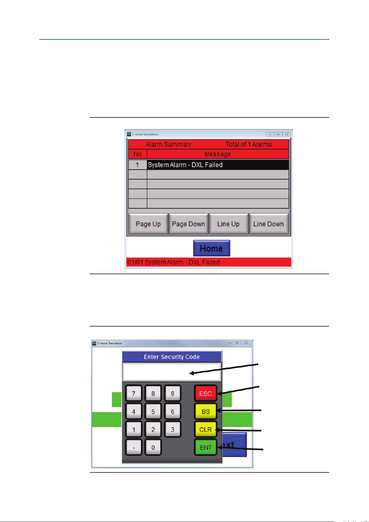
Section 7: LCD Touch Panel Backup Terminal Operation
May 2020
7.1.1 Alarm Display
The alarm display page will display lists of alarms that valve currently has an alarm and including
system alarms.
Refer to Figure 13.
Figure 13
Installation and Operations Manual
MAN-01-09-91-0726-EN Rev. 1
7.1.2 Security Codes Screen
Refer to Figure 14 to view a Security Code Screen. This is where Password Protection screen will
prompted when it required a security code.
Figure 14
Enter Password
Escape or Cancel
Back Space
Clear Contents
Enter
38
LCD Touch Panel Backup Terminal Operation
Page 45
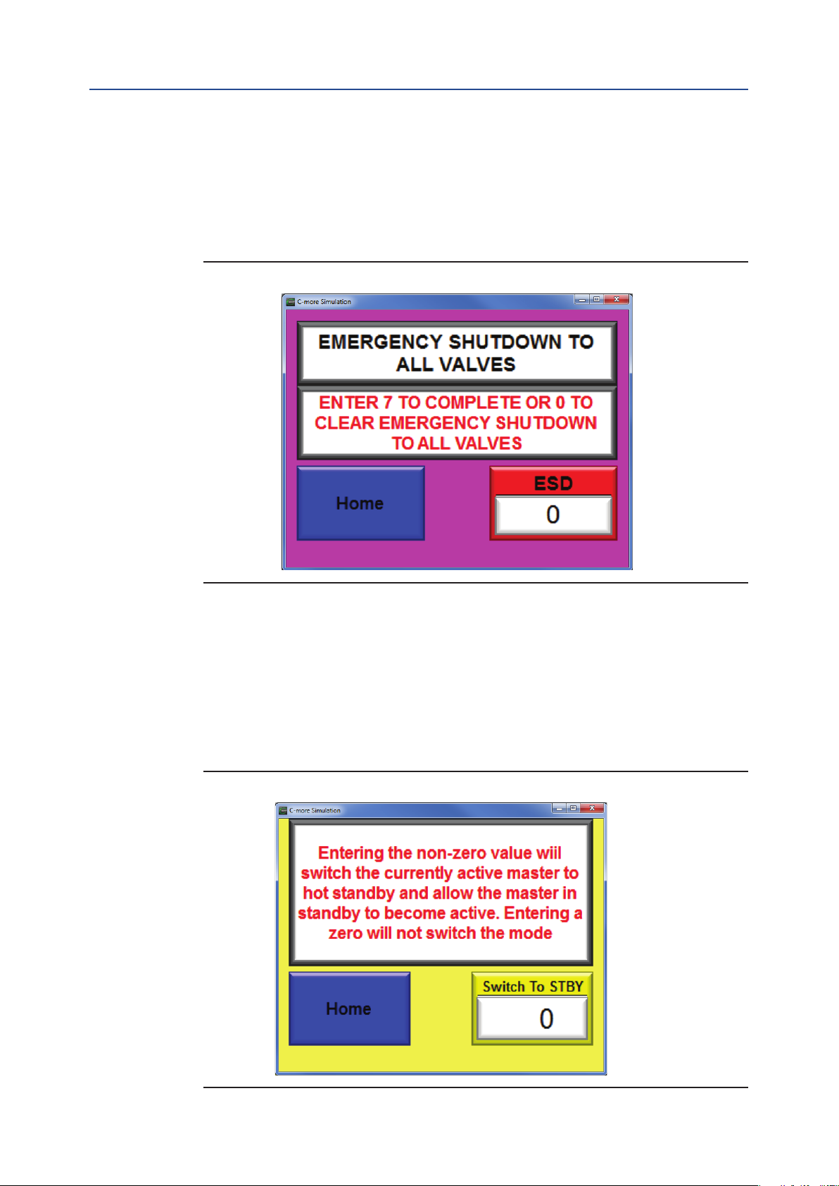
Installation and Operations Manual
MAN-01-09-91-0726-EN Rev. 1 May 2020
Section 7: LCD Touch Panel Backup Terminal Operation
7.1.3 ESD Screen
Emergency Shut Down (ESD) may be sent to all valve by writing 7 cause all actuators to execute ESD.
Writing 0 (zero) will disable (end) ESD.
Refer to Figure 15.
Figure 15
7.1.4 Switch Active Master to Standby Screen
Switching to Hot Standby will cause the active chassis/master to go to hot standby and allow the
chassis currently on standby to switch to the active role. This allows the two masters to be toggled
between active and standby modes. To switch the active master to hot standby mode, press the
“Switch to STBY”. Entering a non-zero value from 1-999 will switch the currently active master to hot
standby and allow the master in standby to become active.
Refer to Figure 16.
Figure 16
LCD Touch Panel Backup Terminal Operation
39
Page 46

Section 7: LCD Touch Panel Backup Terminal Operation
May 2020
Installation and Operations Manual
7.2 Valve Control and Status Display
Valve status, and control is displayed by the LCD touch panel. To select the valve tag number by
pressing the Next Button or Go to Button. When the desired station address or valve tag number
is displayed, the current status of the valve is displayed. The valve status displays the FULL CLOSE
(valve closed), STOPPED (valve stopped in mid-travel), or FULL OPEN (valve open). If the valve is in
transition, the CLOSING will flash while the valve is closing or the OPEN will flash while the valve is
opening. Valve position is updated on the LCD display while the valve is moving. If any alarms occur in
the system or actuator alarm, it will be displayed on the bottom.
Refer to Figure 17.
Figure 17
MAN-01-09-91-0726-EN Rev. 1
User specied valve
Tag Name
Valve Actuator
Network Node
Address
Valve Position
Feedback
Valve Position
Setpoint
Screen
selection Keys
Alarm Display
Area
7.2.1 Valve Control
Valve Control
Keys - OPEN,
STOP, CLOSE
Actuator Selector
Switch Mode (Local,
Stop or Remote)
Valve Status (CLOSED,
OPENING, STOP,
OPEN, OPENING)
Valve Arms
Next and Back to
Select desired
Tag Name
Go To any desired
Tag Name or any
other Screen
40
Status of the desired valve must be displayed before attempting to control the valve. Select the valve
by clicking Next or Goto Button to desired valve address or tag number is displayed. CLOSE, STOP,
OPEN valve control button may then be used to control the valve.
Refer to the above picture Figure 17.
LCD Touch Panel Backup Terminal Operation
Page 47

Installation and Operations Manual
MAN-01-09-91-0726-EN Rev. 1 May 2020
Section 7: LCD Touch Panel Backup Terminal Operation
7.3 Navigation Buttons
Back Button – This button will allow to go back to one Screen (Valve).
Home Button – This button will take back to Home Screen from anywhere on the screen when there
is a Home Button presence.
GoTo Button – This button will allow to jump to any selected valve from the list.
Refer to Figure 18.
Figure 18
Valve Address
Scroll Up and Down for
Desired Screen
Alarms Button – This button will take to Alarms List Screen.
NOTE:
Alarms List Screen only Display Unit Alarm of each Valve when there is an actual Valve Alarm.
To view the Valve alarms please go to Valve Control and Status Screen.
System alarm can also be view on the Alarms List Screen if there is an System Alarms.
The above information can also be seen on the Alarm Bars on the bottom of any Screen.
Next Button – This will allow to go to Next Valve
LCD Touch Panel Backup Terminal Operation
41
Page 48

Section 7: LCD Touch Panel Backup Terminal Operation
May 2020
7.4 Network Diagrams
Up to 25 valves may be monitored on each of 10 network diagram screens for a total of 250 valves.
The valves are shown in the order physically connected to the network. The network node address is
displayed to the right of the valve symbol. Valve position (0-100%) is shown above each valve. Closed
valves are displayed as Green, Open valves are displayed as Red and valves in mid-travel are displayed as
Yellow. If the actuator is in alarm, the valve will ash Magenta as shown for the rst valve in Figure 19.
If a valve is not congured into the system, it will have an address of zero and will be displayed as Yellow.
Touch the NEXT key in the upper right corner of the screen to go to the next network diagram page.
Touch BACK key to go to the previously displayed page. When on Page 10, touch the EXIT key on the
upper right hand corner of Page 10 to return to the Main Menu.
Figure 19
Installation and Operations Manual
MAN-01-09-91-0726-EN Rev. 1
7.5 Network Fault Location
When a network fault alarm occurs, the fault location is shown on the wiring diagram. Figure 20
shows an example of a network fault located between the master Port A and the valve actuator.
Figure 20
42
LCD Touch Panel Backup Terminal Operation
Page 49

Installation and Operations Manual
MAN-01-09-91-0726-EN Rev. 1 May 2020
Section 7: LCD Touch Panel Backup Terminal Operation
7.6 Alarm Display
When any alarm occurs, the alarm is displayed across the bottom of the screen on all screens except
alarm summary and conguration screens. Notice that all operator screens shown in this manual
have an alarm displayed across the bottom. If more than one alarm is present, each alarm is displayed
for ve seconds. Alarms are given an alarm number in sequence of occurrence. To view all alarms,
return to the Main Menu and select Alarms Display as discussed in Section 7.1.1.
Refer to Figure 21.
Figure 21
LCD Touch Panel Backup Terminal Operation
43
Page 50

Section 8: System Setup and Conguration Using LCD Touch Panel
May 2020
Installation and Operations Manual
MAN-01-09-91-0726-EN Rev. 1
Section 8: System Setup and Configuration
Using LCD Touch Panel
The system is shipped from the factory precongured per user supplied data. Only minor edits to
the system conguration should ever be required. It does not matter which master has control during
setup and conguration. Both masters are updated at the same time when a change in conguration
is made.
8.1 Main Menu Screen
From the Main Menu, select the desired screen for system setup or conguration from the menu keys
on the right side of the screen. Operation screen the left side. Each of the setup and conguration
keys/screens will be discussed in the following Sections.
Refer Figure 22.
Figure 22
44
System Setup and Conguration Using LCD Touch Panel
Page 51

Installation and Operations Manual
MAN-01-09-91-0726-EN Rev. 1 May 2020
Section 8: System Setup and Conguration Using LCD Touch Panel
8.2 Security Codes
The system uses security code protection for the system setup screens. Your system may have only
an Engineer security code required to protect the system conguration. Other security codes are
provided by Emerson at the discretion of the owner. To access the system setup the Engineer security
code must be used When any key on the right is touched, the popup window shown in Figure 23 will
be displayed. If you do not have a security code, touch “Cancel.”
Figure 23
8.3 Data Entry
When data entry is required by the system, a data entry screen like that shown in Figure 24 will be
displayed. Only the screen header is different. Enter the desired data and then touch Enter key.
Figure 24
System Setup and Conguration Using LCD Touch Panel
45
Page 52

Section 8: System Setup and Conguration Using LCD Touch Panel
May 2020
8.4 Host Port Conguration
From the Main Menu, touch the “Host Port Cong” key to display the screen shown in Figure 25.
These conguration parameters are only for the two Modbus slave port processors in each of the
two masters. If optional Ethernet ports are installed, the Ethernet setup parameters are cover in a
separate manual. Slave address may be set from 1 to 247. Both ports may be set to the same address
since each port is communicating on a different host link. Baud rate is entered as a whole number as
baud divided by 100. For example, 19200/100 would be 192. When Diagnostic Mode is selected,
the processor will transmit to Port 2 (Debug Port) of the module, Hex ASCII equivalent of all Modbus
messages received and transmitted. This will slow down responses to the host because of the time
required to transmit the debug messages. The Software Version numbers are displayed values for
information only. A decimal point after the most signicant digit is implied.
Figure 25
Installation and Operations Manual
MAN-01-09-91-0726-EN Rev. 1
46
System Setup and Conguration Using LCD Touch Panel
Page 53

Installation and Operations Manual
MAN-01-09-91-0726-EN Rev. 1 May 2020
Section 8: System Setup and Conguration Using LCD Touch Panel
8.5 System Setup
From the Main Menu, touch the “System Setup’ key and the screen shown in Figure 26 will be
displayed. The Baud Rate key is the baud rate for the valve actuator network. Changing the baud
rate requires all actuators on the network to be congured for the same baud rate. Receiver Timeout
is the time the master will wait on a response from a slave (valve actuator). It is normally set for
50 mS. Setting this time too short can cause collisions on the network and setting it too long waists
time when some actuators are not responding, i.e. powered down, etc. The Number of Slaves has to
be the highest network node address assigned to any actuator on the network. It does not have to
be equal to the number of installed actuators. Activate RBE turns on/off Report-By-Exception. Only
Emerson actuators execute RBE for a faster response and improved network performance. Caution
must be used when considering using “Reload Defaults”. This key is security code protected with
the same engineering security code. If this key is used, then all other parameters, including scan list
and device types must be reentered. The “System Reset” key must be used to reset the system after
conguration changes are made. This has the same effect as cycling power to the system except the
LCD touch panel does not have to reinitialize.
Figure 26
System Setup and Conguration Using LCD Touch Panel
47
Page 54

Section 8: System Setup and Conguration Using LCD Touch Panel
May 2020
8.6 Scan List
From the Main Menu, touch the “Scan List” key and the screen shown in Figure 27 will display. The
Scan List is the conguration of the system for the physical location of the actuator node addresses
on the network. The list must be in sequence from Port A of the master around the loop to Port B of
the master. The number on the left of each key is the sequence number which cannot be edited and
the number on the right of each key is the node address for the sequence around the loop based on
physical or network wiring location of the actuator in the loop. Any location may have an address of
zero. If less than 250 actuators are connected to the network, the next sequence number after the
last valve must have a node address of zero. Entering zero for a node address will take that node off
scan. If an actuator is not yet installed, a zero may be entered for its location and then actual address
entered later. If an actuator is removed from the network or if an actuator is going to be powered
down for a long period of time, enter a zero for the node address to take it off scan. There are 50
actuators displayed per page and there are 5 pages for a maximum of 250 actuators.
Figure 27
Sequence
Installation and Operations Manual
MAN-01-09-91-0726-EN Rev. 1
Node
Address
48
System Setup and Conguration Using LCD Touch Panel
Page 55

Installation and Operations Manual
MAN-01-09-91-0726-EN Rev. 1 May 2020
Section 8: System Setup and Conguration Using LCD Touch Panel
8.7 Device Type
From the Main Menu, touch the “Device Type” key and the screen shown in Figure28 will display.
Each Modbus device, including valve actuators, connected to the network must have a device type
assigned. Default device type for Emerson valve actuators is device type 2. If some features of the
actuator are going to be used, then another device type may be required. The number on the left side
of each key is the network node address and cannot be edited. The number on the right of each key
is the device type and may be edited by touching the key to display the data entry popup window.
There are 50 actuators displayed per page and 5 pages for a total of 250 actuators.
Figure 28
Sequence
Device
Type
System Setup and Conguration Using LCD Touch Panel
49
Page 56

Section 9: Valve Network Topology
May 2020
Installation and Operations Manual
MAN-01-09-91-0726-EN Rev. 1
Section 9: Valve Network Topology
9.1 E>Net Ring Network on NEMA BOX or
Rack Mount
Refer to Figure 29.
Figure 29
Ethernet Links
10/100 BaseT
RS232 Modbus RTU
Links at 115.2K baud
NEMA Enclosure
with LCD Touch Pane
50
Valve Network Topology
Page 57

Installation and Operations Manual
MAN-01-09-91-0726-EN Rev. 1 May 2020
Section 9: Valve Network Topology
9.2 Redundant Parallel Bus Networks
Refer to FIgure 30.
Figure 30
Modbus
RS232 Link
Modbus TCP/IP
Ethernet Links
10/100 BaseT
RS232 Modbus RTU
Links at 115.2K baud
19" Rack Mount
Enclosure
or SS NEMA Box
Valve Network Topology
51
Page 58

Section 10: Multiple Masters to DCS
May 2020
Installation and Operations Manual
MAN-01-09-91-0726-EN Rev. 1
Section 10: Multiple Masters to DCS
10.1 Master’s can be Distributed Throughout
the Plant
Using RS485 Host Interface.
Up to 250 actuators per network.
Up to 124 network masters per system.
Refer to Figure 31.
Figure 31
52
Multiple Masters to DCS
Page 59
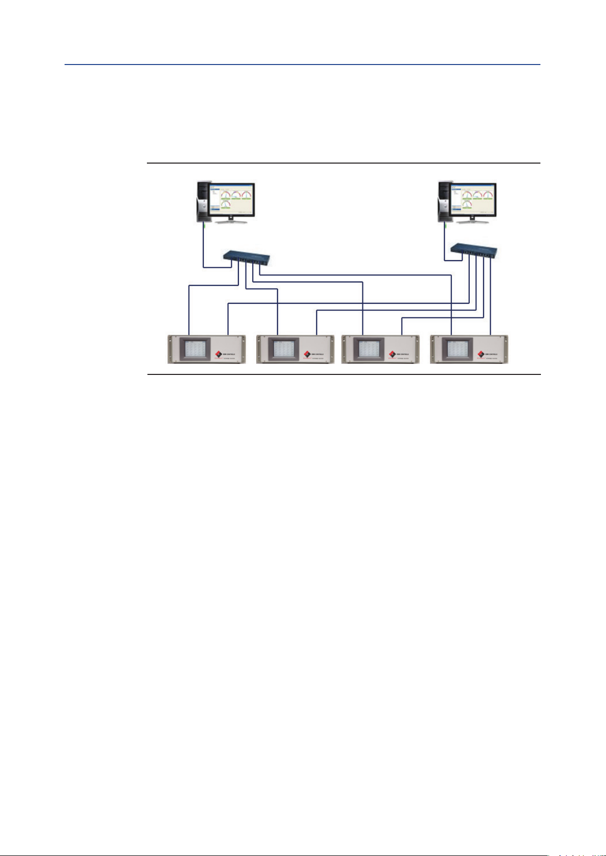
Installation and Operations Manual
MAN-01-09-91-0726-EN Rev. 1 May 2020
Section 10: Multiple Masters to DCS
10.2 Using Ethernet Host Interface
Refer to Figure 32.
Figure 32
Using Ethernet host interface
ICSS ICSS
Valve control system is
is limited only by capacity of
Ethernet TCP/IP 10/100 BaseT
the CDS
Multiple Network to DCS
53
Page 60

Section 10: Multiple Masters to DCS
May 2020
Installation and Operations Manual
MAN-01-09-91-0726-EN Rev. 1
10.3 Using one RS485 and one Ethernet Modbus
TCP/IP Host
Refer to Figure 33.
Figure 33
RS485 LINK
1200-115,200 Baud
Ethernet Links
10/100 BaseT
RS232 Modbus RTU
Links at 115.2K baud
19" Rack Mount
Enclosure
or SS NEMA Box
54
Multiple Masters to DCS
Page 61

Installation and Operations Manual
MAN-01-09-91-0726-EN Rev. 1 May 2020
Notes
This page intentionally left blank
Page 62

World Area Conguration Centers (WACC) offer sales support, service,
inventory and commissioning to our global customers.
Choose the WACC or sales ofce nearest you:
NORTH & SOUTH AMERICA
19200 Northwest Freeway
Houston TX 77065
USA
T +1 281 477 4100
Av. Hollingsworth
325 Iporanga Sorocaba
SP 18087-105
Brazil
T +55 15 3413 8888
ASIA PACIFIC
No. 9 Gul Road
#01-02 Singapore 629361
T +65 6777 8211
No. 1 Lai Yuan Road
Wuqing Development Area
Tianjin 301700
P. R. China
T +86 22 8212 3300
For complete list of sales and manufacturing sites, please visit
www.emerson.com/actuationtechnologieslocations or contact us at
info.actuationtechnologies@emerson.com
MIDDLE EAST & AFRICA
P. O. Box 17033
Jebel Ali Free Zone
Dubai
T +971 4 811 8100
P. O. Box 10305
Jubail 31961
Saudi Arabia
T +966 3 340 8650
24 Angus Crescent
Longmeadow Business Estate East
P.O. Box 6908 Greenstone
1616 Modderfontein Extension 5
South Africa
T +27 11 451 3700
EUROPE
Holland Fasor 6
Székesfehérvár 8000
Hungary
T +36 22 53 09 50
Strada Biffi 165
29017 Fiorenzuola d’Arda (PC)
Italy
T +39 0523 944 411
www.emerson.com
VCIOM-15372-EN ©2020 Emerson. All rights reserved.
The Emerson logo is a trademark and service mark of Emerson Electric Co.
All other marks are property of their respective owners.
The contents of this publication are presented for information purposes
only, and while every effort has been made to ensure their accuracy, they
are not to be construed as warranties or guarantees, express or implied,
regarding the products or services described herein or their use or
applicability. All sales are governed by our terms and conditions, which are
available on request. We reserve the right to modify or improve the designs
or specifications of our products at any time without notice.
 Loading...