

Page 1

Copeland Scroll
™
Compressor
ZFKQ for Refrigeration Applications
Product catalogue
1
Page 2
Emerson developed the ZFKQ range of Copeland Scroll™ compressors to provide the best performance in low
temperatures. The series has a wide application envelope that can operate from -40°C to +7°C evaporating
temperature. Its optimized design perfectly fits frozen food application requirements while its scroll
compliance mechanism makes it highly tolerant of liquid slugging.
The range consists of:
• The ZF*KQE models that operate with liquid injection in order to control discharge temperature and
extend the operating envelope.
• The ZFI*KQE models that are optimized for vapor injection with the use of a subcooler. This boosts the
refrigeration system's cooling capacity and efficiency.
Features and benefits
High efficiency all year round
• The unique Copeland Compliant Scroll design patented by Emerson operates under continuous scroll flank
contact, maintained by centrifugal force. This minimizes gas leakage while maximizing efficiency.
• With its capability for condensing operation down to 4°C on low temperature applications, Copeland
Scroll technology provides the best seasonal efficiencies.
• Equipped with dynamic discharge valve that allows the discharge gas to reach desired pressure. This helps
reduce efficiency loss by preventing gas re-compression.
• The vapor injection technology allows ZFI*KQE compressors to perform higher efficiency than single-stage
compressors at low temperature operation condition. Thus makes ZFI*KQE the best in-class performance.
Compactness
• The small footprint of Copeland Scroll compressors enables compact system designs.
• Weight and dimensions for refrigeration equipment is reduced with increased capacity per compressor
weight.
Robustness and reliability
• The Copeland Compliant Scroll design is tolerant to stresses caused
by liquid slugging, flooded starts and debris commonly found in
refrigeration systems.
• Easy to service and maintain due to their compact size and lightweight,
simple design.
• Engineered for optimum performance with today’s chlorine-free
refrigerants.
• The Copeland Scroll compressor design has several inherent reliability
advantages:
- 70% fewer moving parts than reciprocating compressors
- Axial & radial scroll compliance provides improved liquid handling
capability
- Hermetic design reduces leak potential
• Redesigned suction gas flow results in lower oil circulation and better
motor cooling.
™
• EVI CoreSense
optimum system operation.
2
Control kits provide advanced features to ensure
Page 3

Compressor protection
• ZF*KQE and ZFI*KQE compressors are supplied with internal thermal protectors that prevent motor
overheating in case of loss of phase or low refrigerant charge.
• The ZF*KQE models that operate with liquid injection through DTC Valve in order to control the discharge
temperature.
• The ZFI*KQE models that can operate with Emerson EVI CoreSense
injection superheat as well as a safe discharge temperature.
™
control kits in order to control vapor
Smooth operation
• All Copeland Scroll compressors are designed with a discharge check valve that isolates the high pressure
discharge gas. This allows the compressor to start unloaded, resulting in low inrush currents.
• Smooth operations are made possible by the continuous compression process. This generates less vibration
than reciprocating technology.
Delivers unmatched energy efficiency: 5%–20% improvement
• Motor, scroll and bearing redesign minimize annual energy consumption.
• Precision machined scrolls provide the highest isentropic efficiency and wear-in for improved performance
over time.
• New valving technology adjusts the scroll compression ratio based on operating condition, significantly
improving low ambient performance.
• Using vapor injection improves system capacity by 50% and efficiency by 20% on average at the low
temperature rating condition.
One model for multiple refrigerants
• All ZF and ZFI compressors are qualified for R22, R404A, R507, R407A/C, R407F, R448A, and R449A.
Notes: This catalogue only provides performance tables for R22 and R404A. Please visit Select Software Asia for
more information.
3
Page 4

Table of contents
Features and benefits 02
Nomenclature 05
Bill of material 05
Operating envelopes 06
Product line-up 08
Performance data 09
Technical data 17
EVI CoreSense
™
Dimensional drawings 26
Schematic diagram 43
Available models list 44
Contact list 48
19
4
Page 5

Nomenclature
Base capacity @ LT rating
Low temperature
refrigeration
(Btu/h) @ 60 Hz (ARI)
Generation
Lubricant
Blank Mineral oil
E POE oil
Bill of material
Z F I 20 K Q E - T F D - XXX
Scroll family
Technology
I Vapor injection
Blank Liquid injection
Bill of material
Base capacity multiplier
K 1,000
Motor type
TPThree-phase motor
Motor protection
W External electronic protection
E External enhanced protection
F Internal inherent protection
Electrical codes
7 – 380 V
C 200 V 208-230 V
5 220-220 V 200-230 V
V 200 V 208-230 V
D 380-420 V 460 V
Electrical
Single-phase motor
50 Hz 60 Hz
Compressor
model
ZF06-11KQE TFD, TF5, PFV
ZF13-28KQE TFD,TF7,TFC¹
ZF28KQE TFC
ZF34-54KQE TFD, TF7, TFC
ZFI20-39KQE TFD, TF7, TFC¹
ZFI39KQE TFC
ZFI50-81KQE TFD, TF7, TFC
ZFI122KQE TED, TE7, TEC
Remarks: See technical data sheet for the detailed connection size
ZF06-ZF54KQE only provide rotalock connection to liquid injection fitting for the installation of DTC valve
¹Except ZF28KQE-TFC and ZFI39KQE-TFC
²BOM 554/564 (Sight glass fitting with restriction) only work with Emerson OMB oil management device,
BOM567 (Standard sight glass fitting) works with Emerson OM3 in rack application.
Motor
code
BOM
number
550
551
550
551
580
591
554
564 / 567²
550
552
580
592
554
564 / 567²
522
523
Stub tube
connection
Liquid injection
✓ ✓ ✓
✓ ✓ ✓
✓ ✓ ✓
✓ ✓ ✓
Vapor injection
✓ ✓ ✓
✓ ✓ ✓
✓ ✓ ✓
✓ ✓ ✓
Rotalock
connection
✓ ✓ ✓
✓ ✓ ✓
✓ ✓ ✓
✓ ✓ ✓
✓ ✓ ✓
✓ ✓ ✓
✓ ✓ ✓
✓ ✓ ✓
Oil sight
glass
Schrader
valve
5
Page 6
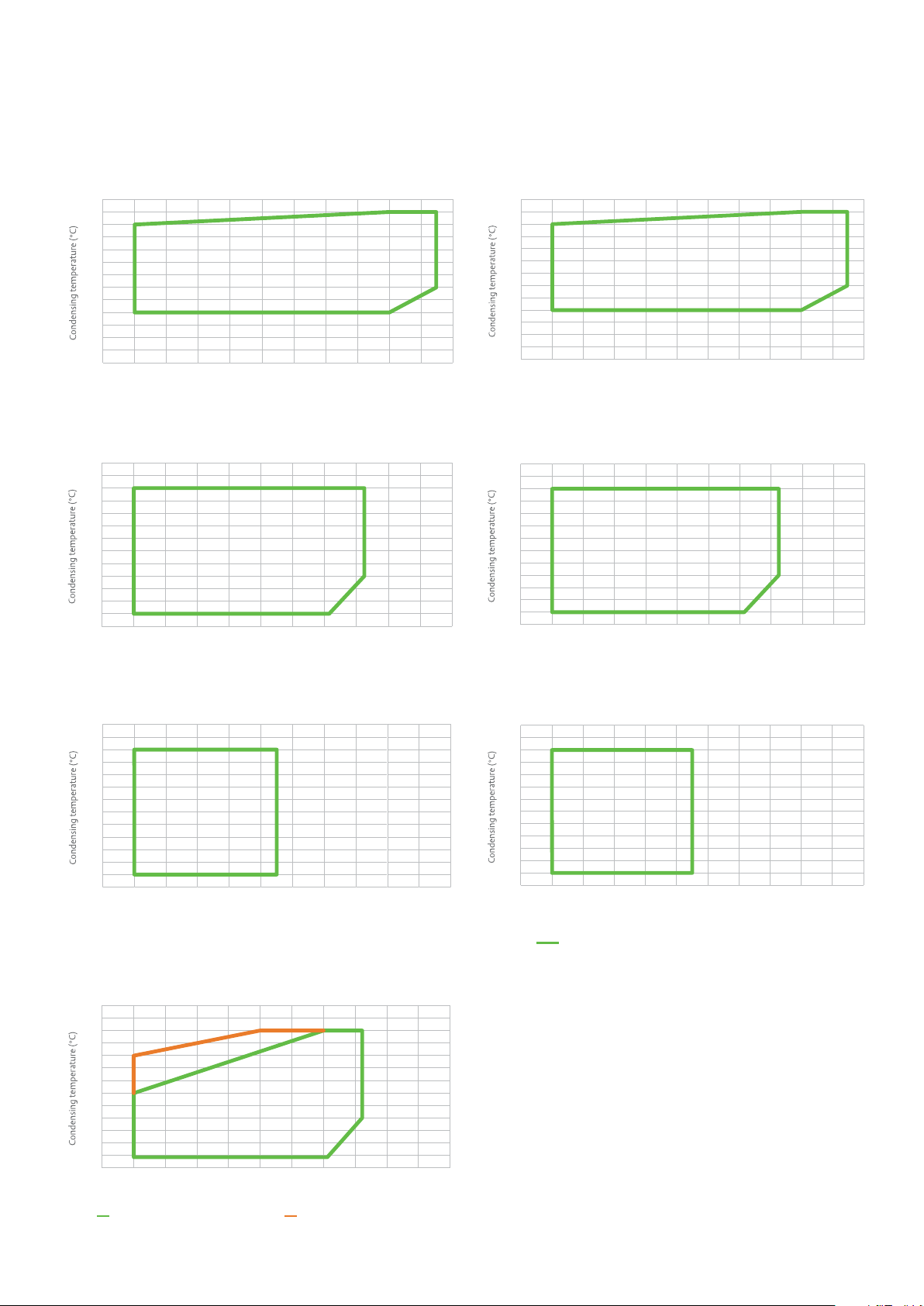
Operating envelopes
65
g
R22
Liquid injectionVapor injection
ZF06 - 18KQEZFI20-26KQE
65
60
55
50
45
40
35
30
25
20
15
10
5
0
-45 -40 -35 -30 -25 -20
Evaporating temperature (°C)
65
60
55
50
45
40
35
30
25
20
15
10
5
0
-45 -40 -35 -30 -25 -20
Evaporating temperature (°C)
-15 -10 -5 0510
-15 -10 -5 0510
65
60
55
50
45
40
35
30
25
20
15
10
5
0
-45 -40 -35 -30 -25 -20
ZF25-41KQEZFI36-59KQE
65
60
55
50
45
40
35
30
25
20
15
10
5
0
-45 -40 -35 -30 -25 -20
Evaporating temperature (°C)
-15 -10 -5 0510
-15 -10 -5 0510
Evaporating temperature (°C)
ZFI122KQE
Note:
65
60
55
50
45
40
35
30
25
20
15
10
5
0
-45 -40 -35 -30 -25 -20
60
55
50
45
40
35
30
25
20
15
10
5
0
-45 -40 -35 -30 -25 -20
20°C Return
as + Vapor injection
Evaporating temperature (°C)
Evaporating temperature (°C)
-15 -10 -5 0510
-15 -10 -5 0510
20K Superheat + Vapor injection
ZF49-54KQEZFI68-81KQE
65
60
55
50
45
40
35
30
25
20
15
10
5
0
-45 -40 -35 -30 -25 -20
Note:
20°C return gas + liquid injection
Evaporating temperature (°C)
-15 -10 -5 0510
6
Page 7
65
Evaporating temperature (°C)
65
60
55
45
35
50
40
30
20
25
15
10
0
-45 -40 -35 -30 -25 -20
Evaporating temperature (°C)
20°C Return
g
as + Vapor injection
-15 -10 -5 0510
5
20K Superheat + Vapor injection
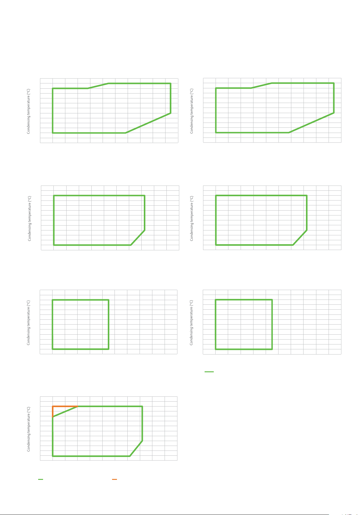
Operating envelopes
R404A
Liquid injectionVapor injection
ZF06 - 18KQEZFI20 - 26KQE
65
60
55
50
45
40
35
30
25
20
15
10
5
0
-45 -40 -35 -30 -25 -20
Evaporating temperature (°C)
65
60
55
50
45
40
35
30
25
20
15
10
5
0
-45 -40 -35 -30 -25 -20
Evaporating temperature (°C)
-15 -10 -5 0510
-15 -10 -5 0510
65
60
55
50
45
40
35
30
25
20
15
10
5
0
-45 -40 -35 -30 -25 -20
ZF25 - 41KQEZFI36 - 59KQE
65
60
55
50
45
40
35
30
25
20
15
10
5
0
-45 -40 -35 -30 -25 -20
Evaporating temperature (°C)
-15 -10 -5 0510
-15 -10 -5 0510
Evaporating temperature (°C)
65
60
55
50
45
40
35
30
25
20
15
10
5
0
-45 -40 -35 -30 -25 -20
ZFI122KQE
Note:
Evaporating temperature (°C)
-15 -10 -5 0510
ZF49-54KQEZFI68-81KQE
60
55
50
45
40
35
30
25
20
15
10
5
0
-45 -40 -35 -30 -25 -20
Note:
20°C return gas + liquid injection
-15 -10 -5 0510
7
Page 8
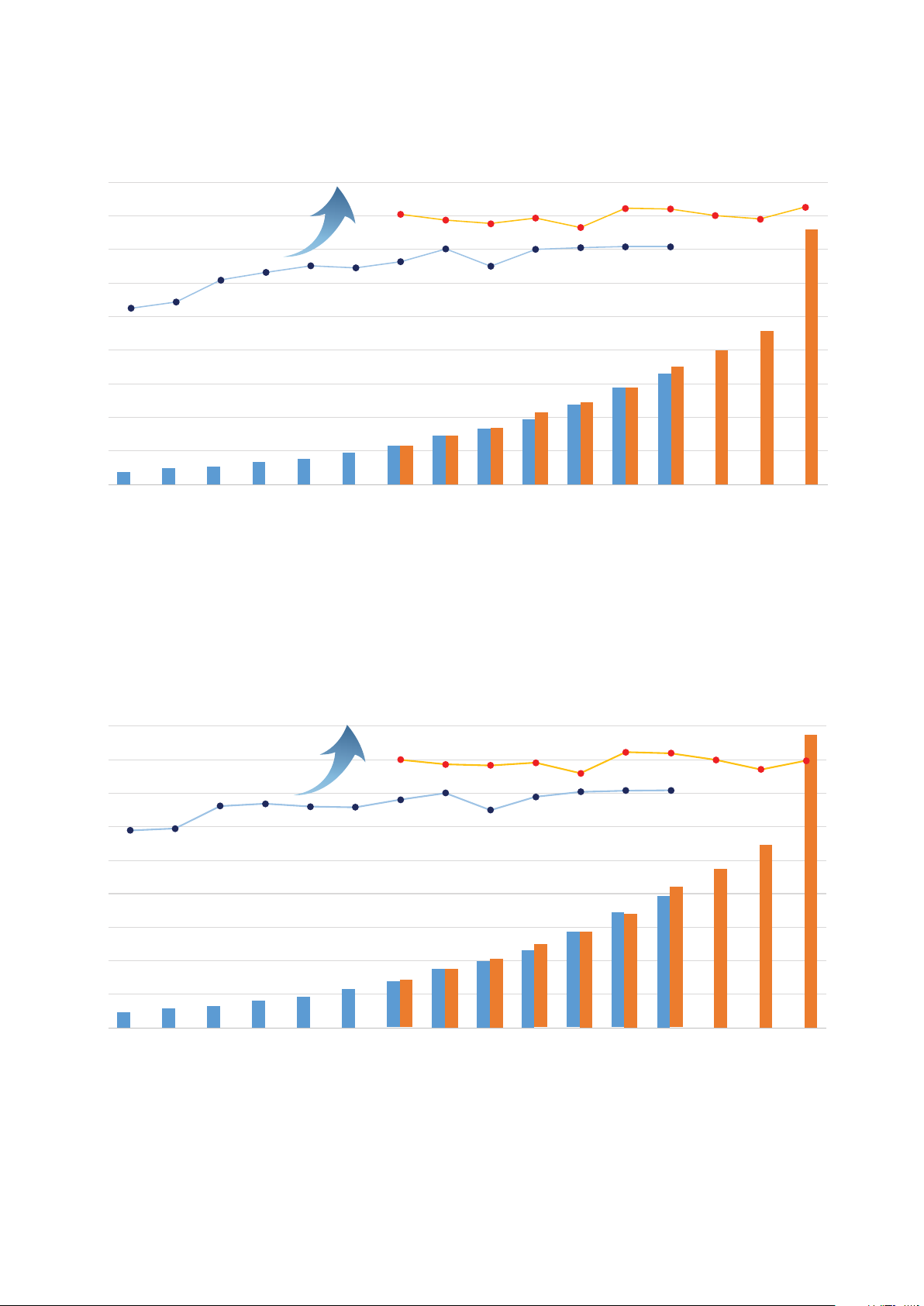
Product line-up
Ca
P
Ca
R404A - 50 Hz
pacity, kW
45
40
35
COP
20%
ZF Liquid injection
30
25
20
15
10
5
0
ZF06 ZF08 ZF09 ZF11 ZF13 ZF15 ZF18
ZFI Vapor injection
ZF25
ZFI20
ZFI23
ZF28
ZFI26
ZF34
ZFI36
ZF41
ZFI39
ZF49
ZFI50
CO
2.0
1.6
1.2
0.8
0.4
0.0
ZF54
ZFI59ZFI68 ZFI81ZFI122
pacity, kW
45
COP
40
35
30
ZF Liquid injection
25
20
15
10
5
0
ZF06 ZF08 ZF09 ZF11 ZF13 ZF15 ZF18
20%
R404A - 60 Hz
ZFI Vapor injection
ZF25
ZFI20
ZFI23
ZF28
ZFI26
ZF34
ZFI36
ZF41
ZFI39
ZF49
ZF54
ZFI50
ZFI59ZFI68 ZFI81ZFI122
COP
2.0
1.6
1.2
0.8
0.4
0.0
Notes: Based on low temperature cold room conditions: -25°C evaporating, 45°C condensing and 20°C return gas temperature.
8
Page 9

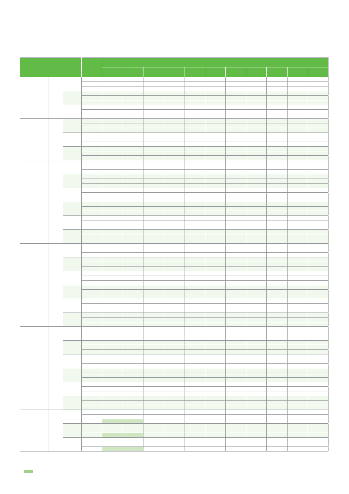
Performance data
TFC: 200 V ; 3-Phase, 50 Hz
TFD: 380-420 V ; 3-Phase, 50 Hz
Liquid injection
Model
ZF06KQE
ZF08KQE
ZF09KQE
ZF11KQE
ZF13KQE
ZF15KQE
ZF18KQE
ZF25KQE
ZF28KQE
ZF34KQE
ZF41KQE
ZF49KQE
ZF54KQE
Notes:
1. Q for capacity; P for power. Units in kW
2. All ZF*KQE values are rated at return gas temperature: 20°C and subcooling: 0 K
TFC
TFD
TFC
TFD
TFC
TFD
TFC
TFD
TFC
TFD
TFC
TFD
TFC
TFD
TFC
TFD
TFC
TFD
TFC
TFD
TFC
TFD
TFC
TFD
TFC
TFD
Cond.
temp.
o
Q
P
Q
P
Q
P
Q
Q
Q
P
Q
P
Q
P
Q
P
Q
Q
Q
P
Q
P
30 1.15 1.46 1.82 2.24 2.73 3.31 3.98 4.74 5.62 6.61 7.05
40 1.05 1.34 1.67 2.06 2.52 3.05 3.66 4.37 5.18 6.10 6.50
50 0.97 1.23 1.53 1.88 2.29 2.77 3.32 3.96 4.70 5.55 5.91
30 1.21 1.24 1.29 1.34 1.40 1.47 1.55 1.65 1.76 1.89 1.95
40 1.43 1.47 1.52 1.58 1.64 1.70 1.78 1.87 1.98 2.10 2.15
50 1.69 1.74 1.79 1.85 1.92 1.99 2.06 2.15 2.25 2.36 2.41
30 1.41 1.79 2.23 2.75 3.36 4.07 4.89 5.83 6.91 8.13 8.66
40 1.29 1.65 2.06 2.54 3.10 3.75 4.50 5.37 6.36 7.50 7.99
50 1.19 1.52 1.89 2.32 2.82 3.40 4.09 4.87 5.78 6.82 7.27
30 1.44 1.48 1.54 1.60 1.67 1.75 1.85 1.96 2.10 2.25 2.32
40 1.70 1.76 1.81 1.88 1.95 2.03 2.12 2.23 2.35 2.50 2.56
50 2.01 2.07 2.14 2.21 2.28 2.36 2.46 2.56 2.68 2.81 2.87
30 1.59 2.01 2.50 3.09 3.78 4.58 5.51 6.58 7.79 9.17 9.77
40 1.46 1.85 2.30 2.84 3.48 4.22 5.07 6.06 7.18 8.46 9.01
50 1.34 1.69 2.11 2.59 3.16 3.83 4.60 5.50 6.52 7.69 8.20
30 1.52 1.57 1.61 1.67 1.72 1.79 1.86 1.94 2.04 2.15 2.19
40 1.80 1.85 1.90 1.95 2.01 2.07 2.14 2.22 2.31 2.41 2.45
50 2.10 2.16 2.22 2.28 2.34 2.41 2.48 2.56 2.65 2.75 2.79
30 1.97 2.49 3.10 3.82 4.67 5.65 6.78 8.07 9.54 11.20 11.91
40 1.81 2.29 2.86 3.52 4.30 5.21 6.26 7.47 8.84 10.39 11.06
50 1.65 2.08 2.59 3.19 3.89 4.72 5.67 6.78 8.04 9.47 10.09
P
P
P
P
30 1.69 1.74 1.81 1.88 1.97 2.08 2.20 2.34 2.50 2.67 2.74
40 2.00 2.06 2.13 2.21 2.30 2.40 2.52 2.65 2.80 2.97 3.04
50 2.37 2.44 2.51 2.59 2.69 2.79 2.91 3.04 3.19 3.35 3.42
30 2.30 2.89 3.60 4.44 5.44 6.60 7.94 9.48 11.23 13.21 14.07
40 2.12 2.66 3.32 4.09 5.01 6.07 7.31 8.73 10.34 12.17 12.97
50 1.93 2.43 3.02 3.72 4.55 5.51 6.63 7.93 9.41 11.08 11.82
30 2.02 2.08 2.15 2.23 2.31 2.41 2.51 2.62 2.74 2.87 2.93
40 2.38 2.45 2.52 2.61 2.70 2.81 2.92 3.04 3.17 3.31 3.37
50 2.79 2.86 2.94 3.04 3.14 3.26 3.38
30 2.79 3.52 4.39 5.42 6.63 8.03 9.63 11.47 13.54 15.87 16.87
40 2.57 3.25 4.05 5.01 6.12 7.42 8.91 10.62 12.55 14.73 15.68
50 2.34 2.95 3.68 4.54 5.56 6.74 8.11 9.68 11.46 13.48 14.35
30 2.47 2.53 2.61 2.70 2.82 2.95 3.11 3.29 3.52 3.78 3.89
40 2.89 2.97 3.06 3.15 3.27 3.40 3.55 3.74 3.95 4.19 4.30
50 3.38 3.47 3.58 3.68 3.81 3.94 4.10 4.28 4.49 4.73 4.83
30 3.25 4.12 5.17 6.42 7.89 9.60 11.58 13.84 16.41 19.31 20.57
40 2.98 3.78 4.75 5.90 7.25 8.82 10.64 12.73 15.11 17.80 18.97
50 2.69 3.42 4.30 5.34 6.56 7.99 9.65 11.55 13.73 16.20 17.27
30 3.13 3.18 3.25 3.33 3.43 3.55 3.69 3.86 4.05 4.27 4.36
40 3.68 3.75 3.82 3.91 4.02 4.14 4.29 4.46 4.65 4.86 4.96
50 4.31 4.39 4.49 4.60 4.72 4.86 5.02 5.20 5.40 5.62 5.72
30 4.08 5.17 6.48 8.04 9.89 12.04 14.52 17.35
40 3.73 4.74 5.95 7.39 9.09 11.06 13.34 15.96
50 3.37 4.29 5.39 6.69 8.22 10.02 12.09 14.48
30 3.93 3.99 4.07 4.17 4.30 4.45 4.63 4.84
40 4.62 4.70 4.79 4.90 5.04 5.19 5.38 5.59
50 5.40 5.50 5.62 5.76 5.92 6.09 6.29 6.52
30 4.79 6.07 7.61 9.45 11.62 14.14 17.06 20.39
40 4.39 5.57 7.00 8.69 10.68 13.00 15.68 18.76
50 3.96 5.04 6.33 7.86 9.66 11.77 14.21 17.02
30 4.72 4.79 4.88 5.01 5.16 5.34 5.55 5.80
40 5.54 5.63 5.75 5.88 6.04 6.23 6.45 6.70
50 6.48 6.61 6.75 6.91 7.10 7.31 7.55 7.82
30 5.31 6.77 8.52 10.59 13.01 15.82 19.06 22.74
40 4.81 6.19 7.83 9.75 12.00 14.59 17.58 20.99
50 4.22 5.51 7.03 8.79 10.84 13.22 15.95 19.06
30 4.32 4.50 4.68 4.87 5.06 5.26 5.46 5.66
40 4.95 5.21 5.46 5.71 5.95 6.19 6.42 6.64
50 5.67 6.02 6.36 6.68 6.98 7.27 7.53 7.77
30 6.35 8.03 10.03 12.41 15.21 18.48 22.26 26.61
40 5.80 7.40 9.27 11.46 14.03 17.01 20.46 24.42
50 5.09 6.61 8.36 10.38 12.72 15.43 18.56 22.15
30 5.24 5.49 5.75 6.01 6.27 6.53 6.80 7.06
40 6.05 6.38 6.71 7.03 7.35 7.66 7.97 8.27
50 6.95 7.36 7.76 8.16 8.53 8.90 9.26 9.61
30 7.81
40 7.10 8.99 11.31 14.08 17.33
50 6.23 8.00 10.16 12.72 15.71
30 6.48 6.68 6.94 7.25 7.59
40 7.52 7.76 8.08 8.45 8.86
50 8.78 9.07 9.43 9.86 10.32
30 8.99 11.36 14.18 17.49 21.36
40 8.31 10.54 13.16 16.23 19.82
50 7.50 9.56 11.96 14.78 18.06
30 4.26 4.73 5.16 5.62 6.14
40 5.54 6.02 6.48 6.95 7.47
50 7.25 7.80 8.31 8.83 9.40
-40 -35 -30 -25 -20 -15 -10 -5 0 5 7
C
9.82 12.30 15.28 18.78
Evap. temp.
R22
o
C
3.51 3.65 3.80 3.87
9
Page 10

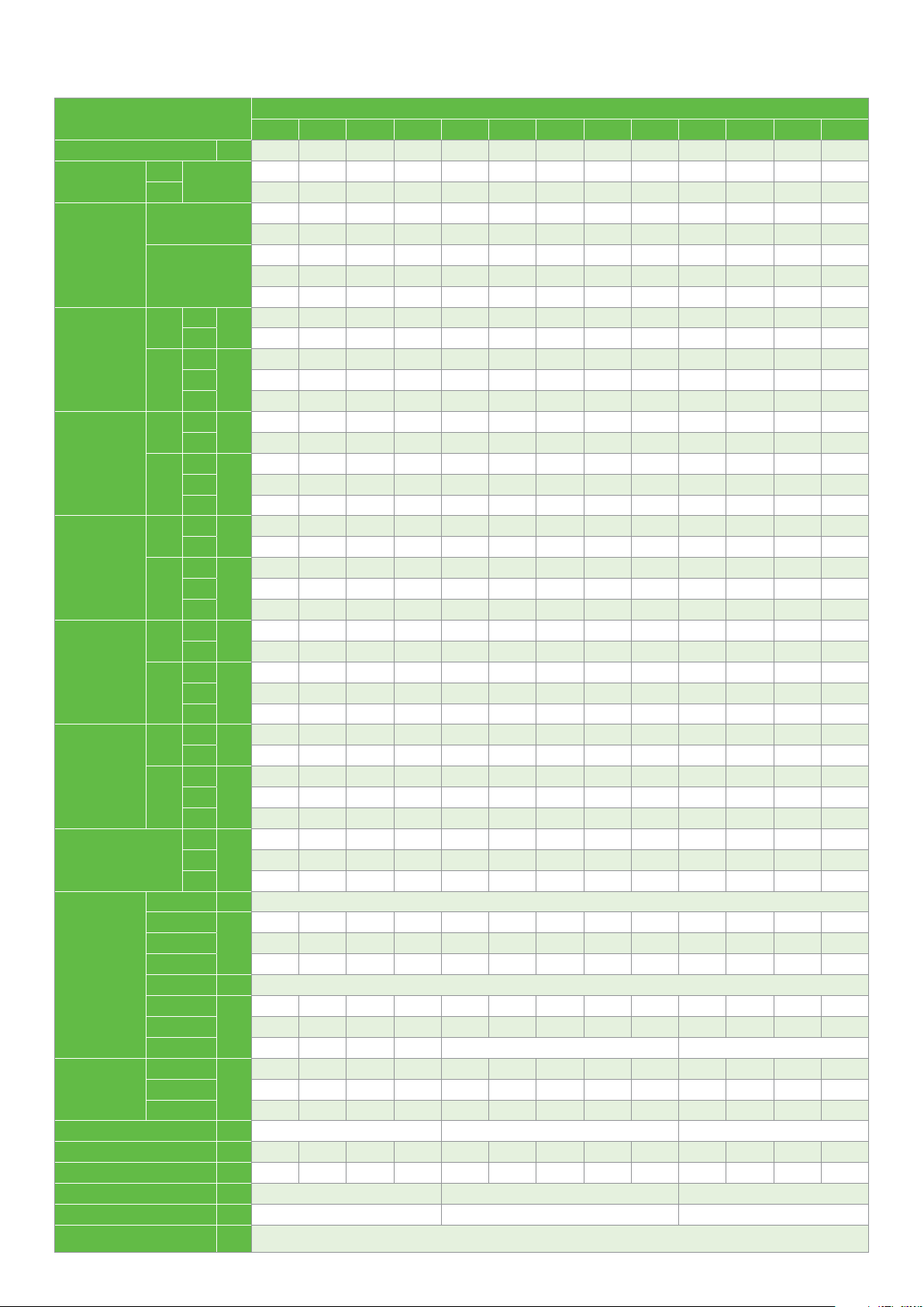
Performance data
TFC: 200 V ; 3-Phase, 50 Hz
TFD: 380-420 V ; 3-Phase, 50 Hz
Vapor injection
R22
Model
ZFI20KQE
ZFI26KQE
ZFI36KQE
ZFI39KQE
ZFI50KQE
ZFI59KQE
ZFI68KQE
ZFI122KQE
Notes:
1. Q for capacity, P for power. Units in kW; LO for liquid out temperature in °C
2. All ZF*KQE values are rated at return gas temperature: 20°C and max subcooling
3. 20K Superheat
TFC
TFD
TFC
TFD
TFC
TFD
TFC
TFD
TFC
TFD
TFC
TFD
TFC
TFD
TEC
TED
temp.
o
Q
P
LO
Q
P
LO
Q
P
LO
Q
P
LO
Q
P
LO
Q
P
LO
Q
P
LO
Q
P
LO
30 2.56 3.22 4.01 4.94 6.00 7.18 8.47 9.87 11.37 12.97 13.64
40 2.55 3.21 3.99 4.90 5.93 7.06 8.30 9.63 11.06 12.56 13.18
50 2.32 2.99 3.78 4.68 5.68 6.78 7.97 9.24 10.59 12.01 12.60
30 2.14 2.18 2.27 2.39 2.55 2.72 2.91 3.09 3.28 3.45 3.51
40 2.39 2.50 2.63 2.76 2.90 3.02 3.13 3.22 3.26 3.27 3.26
50 2.98 3.13 3.27 3.39 3.48 3.53 3.53 3.48 3.37 3.18 3.09
30 -7.70 -6.20 -4.40 -1.80 1.30 4.90 8.80 12.80 16.70 20.60 22.00
40 -4.90 -3.60 -1.70 0.90 4.30 8.10 12.20 16.30 20.40 24.40 25.90
50 3.60 2.60 3.10 5.00 7.90 11.60 15.60 19.80 23.90 28.00 29.50
30 3.85 4.79 5.97 7.36 8.94 10.66 12.51 14.45 16.45 18.49 19.30
40 3.79 4.73 5.89 7.25 8.78 10.45 12.22 14.07 15.96 17.87 18.63
50 3.44 4.38 5.55 6.89 8.38 9.99 11.70 13.47 15.26 17.06 17.77
30 2.98 3.08 3.21 3.36 3.57 3.84 4.19 4.65 5.21 5.91 6.23
40 3.37 3.57 3.75 3.92 4.10 4.31 4.56 4.86 5.24 5.70 5.91
50 4.23 4.49 4.69 4.84 4.95 5.05 5.15 5.26 5.41 5.60 5.69
30 -5.40 -3.40 -1.70 0.50 3.50 7.20 11.50 16.20 21.10 26.10 28.10
40 -2.20 -0.40 1.20 3.50 6.60 10.50 15.00 19.80 24.80 29.90 32.00
50 6.20 5.90 6.20 7.70 10.40 14.10 18.50 23.30 28.40 33.60 35.60
30 5.37 6.66 8.04 9.62 11.52 13.85 16.72 20.25
40 5.00 6.28 7.63 9.17 11.02 13.29 16.09 19.54
50 4.41 5.65 6.96 8.44 10.22 12.42 15.13 18.49
30 3.08 3.38 3.73 4.11 4.51 4.90 5.29 5.64
40 4.00 4.27 4.57 4.90 5.24 5.57 5.88 6.16
50 5.64 5.82 6.03 6.27 6.51 6.73 6.93 7.09
30 -12.40 -11.80 -7.70 -3.60 -0.90 -0.30 -1.70 -5.00
40 -2.20 -3.10 0.10 3.60 5.80 6.10 4.40 0.90
50 5.20 3.80 6.80 10.30 12.40 12.60 10.80 7.20
30 6.15 7.66 9.25 11.06 13.23 15.92 19.27 23.43
40 5.74 7.22 8.77 10.54 12.66 15.28 18.55 22.62
50 5.07 6.51 8.00 9.70 11.74 14.28 17.46 21.42
30 3.50 3.78 4.16 4.60 5.06 5.47 5.80 6.01
40 4.50 4.75 5.10 5.49 5.87 6.22 6.46 6.57
50 6.32 6.49 6.74 7.02 7.30 7.51 7.62 7.58
30 -19.40 -14.90 -10.50 -6.90 -4.30
40 -6.70 -5.20 -2.40 0.40 2.50 3.50 3.40 2.30
50 2.00 2.10 4.50 7.20 9.20 10.20 10.10 9.00
30 7.46 9.11 10.98 13.16 15.76 18.89 22.65 27.14
40 6.89 8.55 10.40 12.54 15.08 18.12 21.77 26.12
50 6.04 7.67 9.48 11.55 14.00 16.92 20.43 24.63
30 4.09 4.41 4.87 5.39 5.92 6.40 6.77 6.99
40 5.26 5.55 5.96 6.42 6.88 7.27 7.55 7.65
50 7.39 7.59 7.88 8.22 8.54 8.78 8.90 8.82
30 -12.90 -11.40 -7.40 -3.50 -0.90 -0.10 -1.00 -3.50
40 -2.20 -2.40 0.40 3.60 5.70 6.20 5.10 2.60
50 5.30 4.40 7.10 10.20 12.30 12.80 11.70 9.10
30 8.79 10.88 13.11 15.67 18.75 22.54 27.23 32.99
40 8.19 10.25 12.43 14.93 17.94 21.63 26.19 31.81
50 7.19 9.20 11.32 13.74 16.64 20.21 24.63 30.10
30 5.07 5.37 5.91 6.57 7.23 7.76 8.05 7.97
40 6.45 6.73 7.23 7.83 8.40 8.83 8.98 8.74
50 9.02 9.20 9.58 10.03 10.43 10.66 10.60 10.12
30 -11.60 -9.20 -5.00 -1.20 1.30 2.20 1.40 -0.70
40 -0.50 -0.20 2.70 5.80 7.80 8.40 7.50 5.10
50 7.30 6.60 9.30 12.30 14.30 14.90 13.90 11.50
30 10.54 12.93 15.57 18.63 22.31
40 9.77 12.15 14.76 17.76 21.34
50 8.55 10.90 13.44 16.35 19.81
30 5.92 6.38 7.04 7.79 8.56
40 7.61 8.03 8.62 9.29 9.95
50 10.69 10.97 11.40 11.89 12.35
30 -9.50 -8.30 -4.20 -0.20 2.30
40 0.70 0.30 3.30 6.70 8.80
50 8.20 7.10 10.00 13.20 15.20
30 19.81 23.68 28.57 34.68 42.18 51.26 62.10 74.88
40 19.42 23.58 28.34 33.36 40.00 47.83 57.05 67.82
50 26.57 31.90 37.83 44.57 52.15 61.16
30 11.73 12.30 12.90 13.56 14.30 15.14 16.12 17.26
40 14.80 15.48 16.12 16.60 17.33 18.11 18.97 19.94
50 20.01 20.72 21.40 21.99 22.76 23.58
30 -20.50 -9.30 -1.90 2.60 4.90 5.50 5.10 3.70
40 -6.70 -3.50 1.70 7.00 11.60 15.10 17.50 18.90
50 9.50 13.50 18.80 24.10 28.60 32.10
-40 -35 -30 -25 -20 -15 -10 -5 0 5 7
C
Cond.
o
Evap. temp.
C
-3.00 -2.90 -3.80
10
Page 11

Performance data
TF7: 380 V ; 3-Phase, 60 Hz
TFC : 208-230 V ; 3-Phase, 60 Hz
TFD : 460 V ; 3-Phase, 60 Hz
Liquid injection
Model
ZF06KQE
ZF08KQE
ZF09KQE
ZF11KQE
ZF13KQE
ZF15KQE
ZF18KQE
ZF25KQE
ZF28KQE
ZF34KQE
ZF41KQE
ZF49KQE
ZF54KQE
Notes:
1. Q for capacity; P for power. Units in kW
2. All ZF*KQE values are rated at return gas temperature: 20°C and subcooling: 0 K
TFC
TFD
TFC
TFD
TFC
TFD
TFC
TFD
TF7
TFC
TFD
TF7
TFC
TFD
TF7
TFC
TFD
TF7
TFC
TFD
TF7
TFC
TFD
TF7
TFC
TFD
TF7
TFC
TFD
TF7
TFC
TFD
TF7
TFC
TFD
Cond.
temp.
o
C
Q
P
Q
P
Q
P
Q
P
Q
P
Q
P
Q
P
Q
P
Q
P
Q
P
Q
P
Q
P
Q
P
30 1.32 1.66 2.08 2.59 3.18 3.87 4.66 5.54 6.54 7.64 8.11
40 1.23 1.55 1.94 2.42 2.97 3.61 4.35 5.17 6.10 7.13 7.57
50 1.15 1.44 1.80 2.23 2.73 3.32 3.99 4.75 5.59 6.54 6.94
30 1.31 1.35 1.39 1.44 1.49 1.56 1.65 1.75 1.88 2.05 2.12
40 1.57 1.60 1.64 1.67 1.71 1.77 1.85 1.95 2.07 2.23 2.30
50 1.90 1.92 1.94 1.96 2.00 2.05 2.12 2.21 2.33 2.48 2.55
30 1.68 2.11 2.64 3.29 4.04 4.92 5.92 7.05 8.31 9.71 10.31
40 1.57 1.97 2.47 3.07 3.78 4.60 5.53 6.58 7.76 9.06 9.62
50 1.46 1.83 2.29 2.83 3.47 4.22 5.07 6.03 7.11 8.31 8.83
30 1.63 1.68 1.73 1.79 1.86 1.94 2.05 2.18 2.34 2.55 2.64
40 1.96 2.00 2.03 2.08 2.13 2.20 2.30 2.42 2.58 2.77 2.86
50 2.36 2.39 2.41 2.44 2.49 2.55 2.63 2.75 2.89 3.08 3.17
30 1.92 2.43 3.03 3.74 4.56 5.52 6.64 7.92 9.38 11.04 11.77
40 1.76 2.24 2.80 3.45 4.20 5.09 6.11 7.29 8.65 10.19 10.86
50 1.62 2.06 2.56 3.14 3.83 4.62 5.55 6.62 7.85 9.26 9.87
30 1.64 1.69 1.75 1.82 1.91 2.00 2.11 2.25 2.40 2.58 2.66
40 1.95 2.01 2.07 2.15 2.23 2.32 2.43 2.55 2.69 2.86 2.93
50 2.30 2.37 2.44 2.52 2.61 2.70 2.81 2.93 3.07 3.22 3.29
30 2.38 3.01 3.75 4.62 5.63 6.81 8.16 9.70 11.46 13.44 14.30
40 2.18 2.76 3.45 4.25 5.19 6.28 7.54 8.99 10.63 12.50 13.31
50 1.98 2.51 3.12 3.84 4.69 5.68 6.83 8.16 9.68 11.40 12.16
30 1.82 1.89 1.98 2.09 2.22 2.37 2.54 2.75 2.97 3.23 3.34
40 2.16 2.24 2.33 2.44 2.57 2.72 2.89 3.08 3.29 3.53 3.63
50 2.57 2.66 2.77 2.88 3.01 3.16 3.32 3.51 3.71 3.94 4.04
30 2.75 3.46 4.33 5.35 6.56 7.96 9.57 11.41 13.49 15.83 16.84
40 2.54 3.20 3.99 4.94 6.04 7.33 8.81 10.51 12.43 14.60 15.54
50 2.30 2.90 3.62 4.48 5.48 6.65 8.00 9.55 11.31 13.31 14.17
30 2.17 2.29 2.41 2.53 2.64 2.75 2.85 2.95 3.04 3.12 3.14
40 2.55 2.67 2.80 2.94 3.08 3.22 3.37 3.53 3.68 3.83 3.90
50 2.97 3.08 3.21 3.36 3.52 3.70
30 3.38 4.27 5.32 6.57 8.02 9.70 11.63 13.82 16.29 19.06 20.25
40 3.12 3.94 4.92 6.07 7.41 8.97 10.76 12.80 15.11 17.70 18.82
50 2.83 3.57 4.46 5.50 6.73 8.15 9.79 11.67 13.80 16.20 17.24
30 2.75 2.84 2.95 3.08 3.25 3.45 3.68 3.96 4.28 4.64 4.80
40 3.21 3.32 3.44 3.58 3.74 3.94 4.16 4.42 4.73 5.07 5.22
50 3.75 3.87 4.01 4.16 4.33 4.53 4.76 5.01 5.30 5.63 5.77
30 3.96 5.02 6.28 7.79 9.56 11.63 14.01 16.75 19.86 23.37 24.89
40 3.65 4.62 5.79 7.17 8.79 10.68 12.87 15.39 18.26 21.50 22.91
50 3.31 4.20 5.26 6.51 7.97 9.69 11.68 13.97 16.59 19.57 20.86
30 3.38 3.43 3.52 3.66 3.83 4.03 4.23 4.44 4.63 4.81 4.88
40 3.94 4.01 4.12 4.29 4.48 4.70 4.94 5.18 5.41 5.62 5.70
50 4.57 4.66 4.80 4.98 5.21 5.46 5.73 6.00 6.27 6.53 6.62
30 4.97 6.29 7.88 9.76 11.99 14.58 17.57 21.00
40 4.57 5.80 7.26 8.99 11.02 13.39 16.14 19.30
50 4.15 5.27 6.59 8.16 10.00 12.15 14.64 17.52
30 4.24 4.30 4.42 4.59 4.81 5.05 5.30 5.56
40 4.95 5.02 5.17 5.37 5.62 5.90 6.19 6.49
50 5.74 5.84 6.01 6.25 6.53 6.85 7.18 7.52
30 5.84 7.39 9.26 11.47 14.08 17.13 20.64 24.67
40 5.37 6.81 8.52 10.56 12.95 15.74 18.97 22.67
50 4.87 6.19 7.74 9.58 11.75 14.28 17.21 20.58
30 5.09 5.15 5.30 5.51 5.77 6.06 6.37 6.68
40 5.93 6.03 6.20 6.45 6.74 7.08 7.43 7.79
50 6.88 7.01 7.22 7.50 7.84 8.21 8.62 9.03
30 6.40 8.16 10.27 12.76 15.68 19.06 22.96 27.40
40 5.79 7.46 9.43 11.75 14.45 17.58 21.18 25.28
50 5.08 6.64 8.47 10.59 13.07 15.92 19.21 22.96
30 5.21 5.42 5.64 5.86 6.10 6.33 6.58 6.82
40 5.96 6.27 6.58 6.88 7.17 7.46 7.73 8.00
50 6.83 7.25 7.66 8.04 8.41 8.75 9.07 9.37
30 7.65 9.67 12.09 14.95 18.32 22.26 26.82 32.06
40 6.99 8.91 11.16 13.81 16.90 20.49 24.65 29.43
50 6.13 7.97 10.07 12.51 15.33 18.59 22.36 26.69
30 6.31 6.62 6.93 7.24 7.55 7.87 8.19 8.51
40 7.29 7.69 8.08 8.47 8.85 9.23 9.60 9.96
50 8.38 8.87 9.35 9.83 10.28 10.73 11.16
30 9.41 11.83 14.82 18.41 22.63
40 8.56 10.84 13.63 16.97 20.88
50 7.50 9.64 12.24 15.32 18.93
30 7.81 8.04 8.36 8.73 9.14
40 9.06 9.35 9.74 10.18 10.67
50 10.58 10.92 11.36 11.88 12.44
30 10.79 13.63 17.01 20.99 25.64
40 9.98 12.65 15.79 19.48 23.79
50 9.00 11.47 14.35 17.73 21.68
30 7.93 8.49 9.01 9.56 10.19
40 9.46 10.05 10.59 11.16 11.79
50 11.51 12.18 12.79 13.41 14.09
-40 -35 -30 -25 -20 -15 -10 -5 0 5 7
Evap. temp.
R22
o
C
3.88 4.09 4.30 4.52 4.61
11.57
11
Page 12

Performance data
TF7: 380 V ; 3-Phase, 60 Hz
TFC : 208-230 V ; 3-Phase, 60 Hz
TFD : 460 V ; 3-Phase, 60 Hz
Vapor injection
Model
ZFI20KQE
ZFI26KQE
ZFI36KQE
ZFI39KQE
ZFI50KQE
ZFI59KQE
ZFI68KQE
ZFI122KQE
Notes:
1. Q for capacity, P for power. Units in kW; LO for liquid out temperature in °C
2. All ZF*KQE values are rated at return gas temperature: 20°C and max subcooling
3. 20K Superheat
TF7
TFC
TFD
TF7
TFC
TFD
TF7
TFC
TFD
TF7
TFC
TFD
TF7
TFC
TFD
TF7
TFC
TFD
TF7
TFC
TFD
TE7
TEC
TED
12
Cond.
temp.
o
C
Q
P
LO
Q
P
LO
Q
P
LO
Q
P
LO
Q
P
LO
Q
P
LO
Q
P
LO
Q
P
LO
30 3.17 3.98 4.96 6.11 7.42 8.88 10.50 12.26 14.16 16.21 17.06
40 3.16 3.98 4.96 6.08 7.35 8.75 10.30 11.97 13.77 15.70 16.50
50 2.88 3.72 4.70 5.81 7.05 8.41 9.89 11.49 13.21 15.02 15.78
30 2.47 2.52 2.62 2.76 2.93 3.14 3.36 3.62 3.88 4.16 4.28
40 2.77 2.91 3.05 3.21 3.36 3.50 3.64 3.77 3.87 3.96 3.99
50 3.46 3.65 3.81 3.94 4.04 4.10 4.12 4.09 4.00 3.86 3.79
30 -6.90 -5.80 -4.00 -1.40 1.80 5.30 8.90 12.50 16.00 19.30 20.50
40 -5.00 -4.00 -2.00 0.90 4.40 8.10 12.00 15.90 19.60 23.10 24.40
50 3.50 2.00 2.60 4.70 7.80 11.40 15.30 19.20 23.00 26.60 28.00
30 4.70 5.84 7.28 8.97 10.89 12.99 15.24 17.60 20.04 22.51 23.50
40 4.63 5.78 7.19 8.85 10.71 12.74 14.89 17.13 19.43 21.75 22.67
50 4.20 5.36 6.77 8.41 10.23 12.20 14.27 16.42 18.60 20.78 21.64
30 3.51 3.64 3.79 3.98 4.23 4.56 4.99 5.54 6.24 7.10 7.50
40 3.95 4.20 4.42 4.63 4.85 5.10 5.41 5.79 6.27 6.86 7.14
50 4.98 5.29 5.52 5.70 5.84 5.96 6.09 6.25 6.45 6.72 6.85
30 -3.00 -1.60 0.00 2.30 5.30 8.80 12.70 16.90 21.30 25.60 27.40
40 -0.30 0.90 2.60 5.00 8.10 11.90 16.00 20.40 24.90 29.40 31.20
50 7.70 6.90 7.30 9.00 11.70 15.30 19.40 23.80 28.40 33.10 34.90
30 6.45 8.00 9.65 11.54 13.82 16.63 20.12 24.42
40 6.00 7.53 9.15 10.99 13.21 15.95 19.35 23.56
50 5.29 6.78 8.35 10.12 12.26 14.91 18.20 22.28
30 3.63 3.99 4.40 4.85 5.32 5.79 6.23 6.62
40 4.73 5.03 5.39 5.78 6.18 6.57 6.93 7.24
50 6.66 6.87 7.12 7.40 7.68 7.94 8.17 8.33
30 -10.70 -10.10 -5.90 -1.70 0.80 1.10 -0.80 -4.70
40 -0.40 -1.40 1.80 5.30 7.40 7.40 5.30 1.30
50 6.70 5.20 8.30 11.80 13.90 13.90 11.70 7.60
30 7.41 9.17 11.08 13.27 15.89 19.09 23.01 27.81
40 6.89 8.64 10.51 12.64 15.20 18.32 22.14 26.82
50 6.08 7.78 9.58 11.64 14.10 17.11 20.81 25.35
30 4.10 4.47 4.93 5.44 5.96 6.47 6.93 7.30
40 5.31 5.63 6.03 6.48 6.93 7.35 7.71 7.98
50 7.46 7.68 7.97 8.28 8.60 8.88 9.09 9.19
30 -17.90
40 -5.00 -3.20 -0.60 2.00 3.90 5.10 5.30 4.80
50 3.60 4.00 6.10 8.60 10.60 11.80 12.10 11.50
30 9.02 11.02 13.28 15.92 19.08 22.86 27.41 32.84
40 8.34 10.35 12.59 15.18 18.25 21.93 26.34 31.61
50 7.30 9.29 11.47 13.98 16.94 20.48 24.72 29.80
30 4.88 5.27 5.82 6.44 7.07 7.64 8.09 8.34
40 6.28 6.64 7.12 7.67 8.22 8.69 9.02 9.14
50 8.83 9.07 9.42 9.82 10.20 10.50 10.63 10.54
30 -12.80 -11.30 -7.40 -3.50 -0.90 -0.10 -0.90 -3.20
40 -2.10 -2.40 0.50 3.60 5.70 6.20 5.30 2.80
50 5.20 4.40 7.10 10.20 12.30 12.80 11.80 9.30
30 10.78 13.13 15.81 18.96 22.71 27.21 32.59 39.00
40 9.96 12.33 14.98 18.07 21.73 26.10 31.31 37.52
50 8.70 11.05 13.65 16.64 20.17 24.37 29.39 35.35
30 5.87 6.45 7.12 7.85 8.61 9.36 10.08 10.73
40 7.63 8.13 8.72 9.35 10.00 10.64 11.23 11.73
50 10.77 11.11 11.52 11.97 12.43 12.85 13.22 13.49
30 -11.50 -8.10 -4.30 -1.10 1.20 2.50 2.80 2.30
40 0.30 1.20 3.40 5.80 7.70 8.70 8.90 8.20
50 7.60 7.70 9.80 12.20 14.10 15.20 15.50 14.90
30 12.64 15.56 18.75 22.45 26.88
40 11.73 14.64 17.78 21.40 25.71
50 10.30 13.15 16.20 19.70 23.86
30 7.03 7.49 8.25 9.16 10.07
40 8.97 9.40 10.10 10.91 11.70
50 12.57 12.85 13.37 13.98 14.53
30 -8.50 -5.20 -1.30 2.10 4.50
40 2.80 3.70 6.30 8.90 10.80
50 10.50 10.40 12.60 15.20 17.10
30 23.12 27.63 33.35 40.48 49.23 59.83 72.48 87.40
40 22.59 27.44 32.99 38.94 46.69 55.83 66.58 79.16
50 30.92 37.15 44.07 51.94 60.87 71.39
30 14.17 14.86 15.58 16.38 17.27 18.30 19.48 20.86
40 17.80 18.63 19.41 20.05 20.93 21.88 22.92 24.09
50 24.10 24.98 25.81 26.57 27.50 28.49
30 -14.60 -3.80 3.30 7.50 9.70 10.40 9.90 8.60
40 -1.30 1.70 6.70 11.80 16.20 19.60 21.80 23.10
50 14.20 18.00 23.20 28.20 32.50 35.90
-40 -35 -30 -25 -20 -15 -10 -5 0 5 7
-13.00 -8.60 -5.20 -2.70 -1.30 -0.90 -1.40
Evap. temp.
R22
o
C
Page 13

Performance data
TFC: 200 V ; 3-Phase, 50 Hz
TFD: 380-420 V ; 3-Phase, 50 Hz
Liquid injection
R404A
Model
ZF06KQE
ZF08KQE
ZF09KQE
ZF11KQE
ZF13KQE
ZF15KQE
ZF18KQE
ZF25KQE
ZF28KQE
ZF34KQE
ZF41KQE
ZF49KQE
ZF54KQE
Notes:
1. Q for capacity; P for power. Units in kW
2. All ZF*KQE values are rated at return gas temperature: 20°C and subcooling: 0 K
TFC
TFD
TFC
TFD
TFC
TFD
TFC
TFD
TFC
TFD
TFC
TFD
TFC
TFD
TFC
TFD
TFC
TFD
TFC
TFD
TFC
TFD
TFC
TFD
TFC
TFD
Cond.
temp.
o
C
Q
P
Q
P
Q
P
Q
P
Q
P
Q
P
Q
P
Q
P
Q
P
Q
P
Q
P
Q
P
Q
P
30 1.28 1.61 2.00 2.47 3.01 3.64 4.38 5.22 6.19 7.28 7.76
40 1.13 1.43 1.77 2.18 2.65 3.21 3.85 4.58 5.43 6.39 6.81
50 0.96 1.22 1.51 1.85 2.25 2.71 3.25 3.87 4.59 5.41 5.77
30 1.17 1.23 1.30 1.37 1.45 1.54 1.64 1.75 1.87 2.00 2.05
40 1.40 1.46 1.52 1.59 1.67 1.76 1.85 1.96 2.08 2.20 2.26
50 1.72 1.77 1.82 1.89 1.96 2.04 2.13 2.24 2.35 2.47 2.52
30 1.58 1.98 2.46 3.03 3.70 4.48 5.38 6.42 7.61 8.96 9.54
40 1.39 1.75 2.18 2.68 3.26 3.94 4.73 5.64 6.68 7.86 8.37
50 1.18 1.50 1.86 2.28 2.77 3.34 4.00 4.76 5.64 6.65 7.10
30 1.39 1.47 1.54 1.63 1.73 1.84 1.95 2.08 2.22 2.37 2.44
40 1.67 1.74 1.81 1.89 1.99 2.09 2.21 2.33 2.47 2.62 2.69
50 2.05 2.10 2.17 2.25 2.33 2.43 2.54 2.66 2.79 2.94 3.00
30 1.71 2.17 2.71 3.35 4.10 4.97 5.97 7.13 8.45 9.96 10.61
40 1.53 1.94 2.41 2.96 3.60 4.35 5.23 6.23 7.39 8.71 9.29
50 1.32 1.67 2.07 2.52 3.06 3.69 4.42 5.27 6.25 7.38 7.88
30 1.46 1.48 1.52 1.57 1.65 1.74 1.84 1.96 2.09 2.23 2.29
40 1.77 1.78 1.81 1.86 1.92 2.00 2.10 2.21 2.33 2.47 2.52
50 2.16 2.16 2.18 2.22 2.27 2.34 2.43 2.53 2.65 2.78 2.84
30 2.17 2.74 3.41 4.19 5.10 6.16 7.41 8.85 10.50 12.39 13.22
40 1.94 2.45 3.03 3.70 4.49 5.41 6.49 7.75 9.20 10.86 11.60
50 1.65 2.09 2.58 3.15 3.81 4.58 5.48 6.55 7.78 9.22 9.86
30 1.79 1.82 1.87 1.94 2.03 2.14 2.27 2.41 2.57 2.75 2.83
40 2.13 2.15 2.20 2.26 2.34 2.45 2.57 2.70 2.85 3.02 3.09
50 2.53 2.56 2.60 2.67 2.75 2.85 2.97 3.10 3.24 3.40 3.47
30 2.45 3.15 3.98 4.93 6.03 7.30 8.74 10.36 12.19 14.24 15.12
40 2.19 2.78 3.48 4.31 5.27 6.38 7.66 9.11 10.76 12.61 13.41
50 1.94 2.40 2.95 3.62 4.42 5.35 6.44 7.70 9.13 10.77 11.48
30 1.87 1.93 2.00 2.08 2.19 2.30 2.44 2.59 2.76 2.95 3.03
40 2.27 2.33 2.41 2.49 2.59 2.70 2.83 2.97 3.13 3.30 3.37
50 2.78 2.85 2.93 3.02 3.12 3.23 3.35
30 3.01 3.89 4.91 6.08 7.44 9.01 10.82 12.89 15.26 17.93 19.10
40 2.66 3.42 4.29 5.30 6.47 7.84 9.43 11.26 13.36 15.76 16.81
50 2.36 2.95 3.64 4.44 5.40 6.53 7.86 9.41 11.22 13.31 14.22
30 2.21 2.33 2.45 2.58 2.73 2.90 3.09 3.31 3.56 3.85 3.97
40 2.68 2.82 2.95 3.09 3.24 3.41 3.60 3.80 4.04 4.30 4.41
50 3.26 3.42 3.58 3.73 3.90 4.07 4.25 4.45 4.67 4.92 5.02
30 3.70 4.70 5.85 7.20 8.78 10.64 12.81 15.33 18.25 21.58 23.04
40 3.29 4.17 5.17 6.34 7.70 9.30 11.17 13.36 15.91 18.84 20.13
50 2.81 3.57 4.41 5.37 6.50 7.83 9.40 11.25 13.42 15.94 17.06
30 2.79 2.89 3.01 3.14 3.29 3.46 3.65 3.85 4.07 4.30 4.40
40 3.29 3.40 3.53 3.67 3.83 4.00 4.18 4.38 4.59 4.82 4.91
50 3.92 4.04 4.18 4.33 4.49 4.67 4.85 5.05 5.26 5.48 5.57
30 4.59 5.81 7.32 9.08 11.09 13.32 15.75 18.37
40 4.09 5.12 6.42 7.96 9.73 11.71 13.87 16.20
50 3.63 4.45 5.50 6.79 8.28 9.96 11.81 13.82
30 3.03 3.31 3.54 3.76 4.00 4.30 4.67 5.16
40 3.43 3.80 4.11 4.39 4.69 5.03 5.44 5.95
50 3.84 4.31 4.72 5.09 5.46 5.85 6.32 6.87
30 5.25 6.65 8.36 10.38 12.67 15.22 18.00 21.00
40 4.67 5.85 7.34 9.10 11.12 13.38 15.85 18.51
50 4.15 5.08 6.29 7.76 9.46 11.39 13.50 15.79
30 3.74 4.08 4.37 4.64 4.94 5.30 5.76 6.37
40 4.23 4.68 5.07 5.42 5.78 6.20 6.71 7.34
50 4.74 5.32 5.82 6.28 6.73 7.22 7.79 8.48
30 6.03 7.72 9.67 11.94 14.57 17.62 21.16 25.23
40 5.30 6.82 8.54 10.51 12.79 15.44 18.51 22.06
50 4.47 5.79 7.25 8.90 10.81 13.01 15.59 18.58
30 4.18 4.41 4.67 4.93 5.22 5.53 5.85 6.20
40 4.85 5.16 5.46 5.77 6.08 6.40 6.73 7.07
50 5.66 6.04 6.41 6.77 7.13 7.48 7.82 8.16
30 7.57 9.62 11.96 14.69 17.88 21.62 25.98 31.04
40 6.71 8.56 10.62 12.98 15.71 18.90 22.64 26.99
50 5.65 7.29 9.06 11.04 13.31 15.96 19.05 22.68
30 5.07 5.40 5.75 6.11 6.48 6.88 7.30 7.75
40 5.95 6.33 6.72 7.12 7.52 7.94 8.36 8.81
50 6.95 7.40 7.85 8.29 8.74 9.18 9.63 10.09
30 9.14
40 8.07 10.21 12.72 15.65 19.05
50 6.80 8.66 10.80 13.27 16.14
30 6.24 6.53 6.90 7.33 7.81
40 7.36 7.67 8.06 8.52 9.02
50 8.73 9.07 9.48 9.97 10.51
30 10.46 13.21 16.47 20.31 24.80
40 9.23 11.69 14.56 17.91 21.80
50 7.78 9.91 12.36 15.19 18.47
30 7.14 7.47 7.90 8.39 8.94
40 8.42 8.77 9.22 9.75 10.33
50 9.99 10.37 10.85 11.41 12.03
-40 -35 -30 -25 -20 -15 -10 -5 0 5 7
11.54 14.39 17.75 21.67
Evap. temp.
o
C
3.48 3.62 3.78 3.85
13
Page 14

Performance data
TFC: 200 V ; 3-Phase, 50 Hz
TFD: 380-420 V ; 3-Phase, 50 Hz
Vapor injection
R404A
Model
ZFI20KQE
ZFI26KQE
ZFI36KQE
ZFI39KQE
ZFI50KQE
ZFI59KQE
ZFI68KQE
ZFI81KQE
ZFI122KQE
Notes:
1. Q for capacity, P for power. Units in kW; LO for liquid out temperature in °C
2. All ZF*KQE values are rated at return gas temperature: 20°C and max subcooling
3. 20K Superheat
TFC
TFD
TFC
TFD
TFC
TFD
TFC
TFD
TFC
TFD
TFC
TFD
TFC
TFD
TFC
TFD
TEC
TED
temp.
o
C
Q
P
LO
Q
P
LO
Q
P
LO
Q
P
LO
Q
P
LO
Q
P
LO
Q
P
LO
Q
P
LO
Q
P
LO
30 3.43 4.28 5.23 6.30 7.50 8.86 10.40 12.14 14.09 16.28 17.23
40 3.25 4.07 4.99 6.04 7.23 8.60 10.14 11.90 13.88 16.11 17.08
50 2.92 3.70 4.59 5.62 6.80 8.17 9.73 11.50 13.51 15.76 16.74
30 2.17 2.23 2.30 2.38 2.46 2.53 2.58 2.62 2.62 2.59 2.57
40 2.73 2.78 2.84 2.92 3.01 3.09 3.16 3.22 3.25 3.27 3.26
50 3.56 3.58 3.62 3.68 3.75 3.82 3.90 3.96 4.01 4.04 4.05
30 -13.50 -9.80 -6.10 -2.00 2.30 6.50 10.50 14.20 17.40 20.00 20.90
40 -6.70 -4.80 -2.20 1.00 4.60 8.30 12.00 15.40 18.20 20.60 21.40
50 6.00 4.80 5.10 6.50 8.90 11.60 14.50 17.20 19.70 21.80 22.50
30 5.14 6.29 7.61 9.14 10.90 12.91 15.20 17.79 20.72 24.02 25.44
40 5.09 6.12 7.33 8.74 10.39 12.30 14.49 17.01 19.86 23.06 24.45
50 5.08 5.97 7.03 8.32 9.84 11.62 13.70 16.10 18.83 21.94 23.30
30 3.22 3.38 3.54 3.70 3.84 3.98 4.11 4.24 4.37 4.50 4.55
40 3.85 4.07 4.28 4.47 4.65 4.81 4.97 5.12 5.26 5.39 5.44
50 4.74 5.01 5.26 5.50 5.70 5.90 6.07 6.24 6.38 6.52 6.57
30 -13.00 -8.10 -4.00 -0.10 3.70 7.20 10.50 13.60 16.10 18.10 18.80
40 -10.10 -5.20 -0.80 3.30 7.30 10.90 14.20 17.10 19.50 21.50 22.10
50 -7.30 -2.10 2.60 7.00 11.10 14.90 18.20 21.00 23.40 25.10 25.70
30 6.48 8.01 9.76 11.70 13.85 16.20 18.73 21.45
40 6.29 7.67 9.27 11.08 13.09 15.32 17.74 20.32
50 6.24 7.42 8.82 10.43 12.26 14.30 16.54 18.97
30 3.78 4.05 4.29 4.52 4.75 4.97 5.19 5.42
40 4.46 4.86 5.21 5.52 5.80 6.05 6.27 6.47
50 5.21 5.78 6.29 6.72 7.09 7.42 7.69 7.91
30 -13.80 -10.00 -5.40 -0.70 3.90 8.10 12.00 15.40
40 -10.80 -5.80 -0.50 4.50 9.10 13.20 16.90 20.20
50 -11.10 -3.70 3.00 9.00 14.20 18.50 22.30 25.40
30 7.44 9.19 11.19 13.43 15.89 18.58 21.49 24.61
40 7.22 8.80 10.63 12.71 15.04 17.58 20.35 23.34
50 7.16 8.51 10.12 11.97 14.06 16.41 18.97 21.76
30 4.49 4.81 5.10 5.38 5.64 5.91 6.17 6.45
40 5.30 5.78 6.19 6.56 6.90 7.19 7.46 7.70
50 6.19 6.87 7.47 7.99 8.43 8.82 9.14 9.40
30 -13.80 -10.00 -5.40 -0.70 3.90
40 -10.80 -5.80 -0.50 4.50 9.00 13.20 16.90 20.10
50 -11.10 -3.70 3.00 9.00 14.20 18.50 22.30 25.40
30 9.11 10.80 12.99 15.63 18.68 22.06 25.71 29.59
40 8.66 10.29 12.40 14.91 17.77 20.94 24.34 27.91
50 8.04 9.65 11.68 14.07 16.79 19.75 22.91 26.23
30 5.04 5.42 5.76 6.08 6.38 6.67 6.98 7.31
40 6.06 6.49 6.89 7.26 7.61 7.97 8.33 8.72
50 7.31 7.79 8.25 8.67 9.09 9.50 9.92 10.38
30 -18.10 -7.60 -2.60 0.50 3.40 6.70 10.50 14.80
40 -12.10 -2.70 1.90 5.00 8.10 11.70 15.70 20.20
50 -3.60 3.70 7.30 10.10 13.10 16.70 20.80 25.20
30 11.10 13.15 15.82 19.05 22.74 26.86 31.31 36.02
40 10.55 12.53 15.09 18.16 21.65 25.51 29.65 34.01
50 9.80 11.75 14.21 17.14 20.45 24.05 27.92 31.93
30 6.15 6.61 7.03 7.41 7.77 8.14 8.51 8.92
40 7.39 7.91 8.39 8.85 9.29 9.72 10.17 10.65
50 8.92 9.51 10.05 10.58 11.09 11.58 12.11 12.66
30 -15.40 -5.10 -0.30 2.70 5.60 8.80 12.60 16.70
40 -9.50 -0.30 4.20 7.20 10.20 13.60 17.50 21.80
50 -1.20 5.90 9.50 12.10 15.00 18.60 22.50 26.90
30 12.60 14.92 17.95 21.61 25.81
40 11.97 14.23 17.13 20.60 24.56
50 11.12 13.33 16.14 19.45 23.20
30 7.15 7.68 8.17 8.62 9.04
40 8.60 9.20 9.77 10.29 10.80
50 10.36 11.05 11.70 12.30 12.89
30 -15.40 -5.10 -0.30 2.70 5.50
40 -9.60 -0.40 4.10 7.20 10.20
50 -1.20 5.90 9.40 12.10 15.00
30 14.37 17.01 20.46 24.63 29.43
40 13.66 16.23 19.55 23.50 28.03
50 12.68 15.21 18.41 22.18 26.47
30 8.26 8.87 9.44 9.96 10.45
40 9.94 10.64 11.30 11.90 12.49
50 11.98 12.78 13.53 14.23 14.91
30 -10.00 -0.20 4.40 7.30 9.90
40 -4.50 4.20 8.50 11.40 14.20
50 3.50 10.20 13.60 16.10 18.80
30 23.14 27.67 33.39 40.53 49.30 59.91 72.57 87.50
40 21.96 26.81 32.42 38.99 46.75 55.91 66.68 79.27
50 18.04 23.62 30.52 36.81 43.84 51.83 60.98 71.51
30 13.14 13.77 14.45 15.18 16.01 16.96 18.06 19.33
40 16.21 17.02 17.80 18.59 19.40 20.28 21.24 22.32
50 20.57 21.72 22.09 22.95 23.78 24.62 25.48 26.39
30 -10.40 -2.80 2.10 5.00 6.40 6.60 5.90 4.60
40 -0.90 1.10 4.60 8.10 11.00 13.20 14.60 15.20
50 16.20 10.20 10.00 12.50 16.10
-40 -35 -30 -25 -20 -15 -10 -5 0 5 7
Cond.
o
Evap. temp.
C
8.10 12.00 15.40
19.50 22.40 24.40
14
Page 15

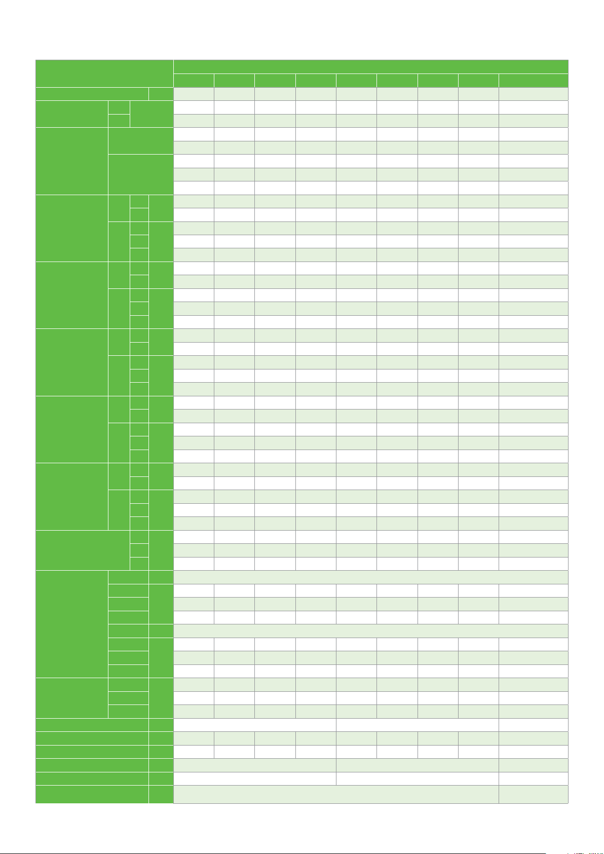
Performance data
TF7: 380 V ; 3-Phase, 60 Hz
TFC : 208-230 V ; 3-Phase, 60 Hz
TFD : 460 V ; 3-Phase, 60 Hz
Liquid injection
R404A
Model
ZF06KQE
ZF08KQE
ZF09KQE
ZF11KQE
ZF13KQE
ZF15KQE
ZF18KQE
ZF25KQE
ZF28KQE
ZF34KQE
ZF41KQE
ZF49KQE
ZF54KQE
Notes:
1. Q for capacity; P for power. Units in kW
2. All ZF*KQE values are rated at return gas temperature: 20°C and subcooling: 0 K
TFC
TFD
TFC
TFD
TFC
TFD
TFC
TFD
TF7
TFC
TFD
TF7
TFC
TFD
TF7
TFC
TFD
TF7
TFC
TFD
TF7
TFC
TFD
TF7
TFC
TFD
TF7
TFC
TFD
TF7
TFC
TFD
TF7
TFC
TFD
Cond.
temp.
o
C
Q
P
Q
P
Q
P
Q
P
Q
P
Q
P
Q
P
Q
P
Q
P
Q
P
Q
P
Q
P
Q
P
30 1.49 1.90 2.36 2.90 3.53 4.26 5.12 6.12 7.27 8.59 9.17
40 1.30 1.67 2.09 2.56 3.10 3.74 4.48 5.34 6.34 7.49 7.99
50 1.11 1.45 1.80 2.20 2.65 3.17 3.78 4.49 5.32 6.29 6.72
30 1.27 1.29 1.34 1.43 1.52 1.63 1.74 1.84 1.93 1.99 2.00
40 1.57 1.57 1.60 1.67 1.77 1.88 2.00 2.12 2.22 2.32 2.34
50 1.94 1.90 1.92 1.97 2.06 2.17 2.30 2.43 2.56 2.68 2.72
30 1.90 2.39 2.98 3.66 4.47 5.42 6.51 7.76 9.20 10.83 11.53
40 1.68 2.12 2.64 3.24 3.95 4.77 5.72 6.81 8.07 9.50 10.12
50 1.42 1.81 2.25 2.76 3.35 4.03 4.83 5.76 6.82 8.04 8.58
30 1.57 1.63 1.71 1.80 1.92 2.04 2.17 2.32 2.46 2.61 2.66
40 1.91 1.95 2.01 2.09 2.20 2.32 2.45 2.60 2.75 2.91 2.98
50 2.40 2.40 2.44 2.50 2.59 2.69 2.82 2.96 3.11 3.27 3.34
30 2.11 2.67 3.32 4.08 4.98 6.02 7.23 8.62 10.23 12.05 12.85
40 1.87 2.37 2.94 3.60 4.37 5.27 6.32 7.53 8.93 10.54 11.24
50 1.60 2.03 2.51 3.06 3.71 4.46 5.34 6.36 7.56 8.94 9.55
30 1.58 1.63 1.69 1.78 1.88 2.01 2.15 2.31 2.49 2.68 2.76
40 1.92 1.95 2.01 2.09 2.18 2.30 2.44 2.59 2.76 2.95 3.03
50 2.34 2.37 2.41 2.48 2.56 2.67 2.80 2.95 3.12 3.30 3.38
30 2.60 3.30 4.11 5.07 6.19 7.49 8.99 10.72 12.68 14.90 15.87
40 2.33 2.94 3.65 4.48 5.46 6.59 7.90 9.41 11.13 13.10 13.95
50 1.99 2.52 3.11 3.81 4.62 5.57 6.68 7.96 9.44 11.14 11.88
30 1.90 1.97 2.06 2.18 2.33 2.50 2.70 2.92 3.17 3.45 3.57
40 2.30 2.37 2.46 2.57 2.71 2.86 3.05 3.25 3.48 3.74 3.85
50 2.79 2.86 2.95 3.06 3.19 3.35 3.52 3.71 3.93 4.17 4.27
30 2.95 3.80 4.79 5.93 7.24 8.73 10.40 12.29 14.40 16.74 17.74
40 2.60 3.32 4.16 5.15 6.31 7.63 9.14 10.85 12.77 14.92 15.85
50 2.28 2.83 3.50 4.31 5.27 6.39 7.70 9.20 10.91 12.84 13.68
30 2.24 2.30 2.39 2.50 2.65 2.82 3.03 3.28 3.56 3.89 4.03
40 2.70 2.76 2.85 2.95 3.09 3.25 3.44 3.67 3.92 4.22 4.35
50 3.30 3.37 3.45 3.55 3.68
30 3.74 4.72 5.88 7.25 8.86 10.73 12.90 15.40 18.26 21.50 22.91
40 3.30 4.16 5.17 6.35 7.74 9.36 11.24 13.41 15.91 18.76 20.00
50 2.81 3.54 4.38 5.36 6.51 7.85 9.43 11.27 13.39 15.83 16.90
30 2.70 2.79 2.92 3.07 3.26 3.49 3.78 4.13 4.54 5.02 5.24
40 3.19 3.34 3.49 3.66 3.85 4.07 4.32 4.62 4.96 5.36 5.54
50 3.77 3.98 4.19 4.40 4.62 4.84 5.08 5.36 5.66 6.01 6.16
30 4.46 5.67 7.07 8.70 10.61 12.84 15.43 18.42 21.87 25.81 27.53
40 3.98 5.05 6.26 7.66 9.29 11.21 13.44 16.04 19.05 22.51 24.03
50 3.47 4.37 5.37 6.53 7.87 9.46 11.32 13.51 16.06 19.03 20.34
30 3.27 3.37 3.52 3.72 3.96 4.24 4.55 4.88 5.23 5.59 5.73
40 3.88 3.98 4.13 4.34 4.59 4.87 5.19 5.53 5.88 6.24 6.39
50 4.57 4.68 4.85 5.07 5.33 5.63 5.96 6.31 6.68 7.05 7.20
30 5.52 7.01 8.78 10.86 13.27 16.05 19.21 22.79
40 4.93 6.19 7.72 9.53 11.67 14.15 17.01 20.27
50 4.44 5.42 6.65 8.15 9.96 12.10 14.60 17.48
30 3.63 3.96 4.28 4.60 4.90 5.21 5.53 5.87
40 4.06 4.50 4.91 5.30 5.68 6.04 6.41 6.78
50 4.46 5.03 5.56 6.06 6.52 6.97 7.40 7.82
30 6.31 8.01 10.03 12.41 15.16 18.33 21.94 26.03
40 5.63 7.07 8.82 10.89 13.33 16.17 19.43 23.15
50 5.07 6.19 7.59 9.31 11.38 13.82 16.67 19.97
30 4.47 4.89 5.29 5.67 6.05 6.43 6.83 7.25
40 5.00 5.55 6.06 6.54 7.00 7.45 7.90 8.36
50 5.50 6.21 6.86 7.47 8.05 8.59 9.12 9.64
30 7.22 9.25 11.58 14.29 17.44 21.10 25.33 30.21
40 6.34 8.16 10.22 12.59 15.32 18.49 22.16 26.41
50 5.35 6.93 8.68 10.66 12.94 15.58 18.66 22.24
30 5.08 5.37 5.68 6.01 6.36 6.73 7.13 7.55
40 5.91 6.28 6.65 7.02 7.40 7.79 8.19 8.60
50 6.89 7.35 7.80 8.25 8.68 9.10 9.52 9.93
30 9.12 11.59 14.41 17.70 21.55 26.05 31.30 37.40
40 8.09 10.31 12.80 15.64 18.93 22.78 27.27 32.51
50 6.81 8.79 10.92 13.30 16.04 19.22 22.96 27.33
30 6.11 6.51 6.92 7.36 7.81 8.29 8.80 9.34
40 7.17 7.63 8.10 8.57 9.06 9.56 10.08 10.61
50
30 11.01 13.90 17.34 21.38 26.11
40 9.72 12.31 15.33 18.85 22.95
50 8.19 10.44 13.01 15.99 19.44
30 7.52 7.87 8.31 8.83 9.41
40 8.86 9.24 9.71 10.26 10.87
50 10.52 10.92 11.43 12.01 12.67
30 12.55 15.85 19.76 24.38 29.76
40 11.08 14.03 17.47 21.49 26.17
50 9.33 11.90 14.83 18.23 22.16
30 8.57 8.97 9.48 10.07 10.73
40 10.10 10.53 11.07 11.70 12.39
50 11.99 12.45 13.02 13.69 14.44
-40 -35 -30 -25 -20 -15 -10 -5 0 5 7
8.37 8.92 9.45 9.99 10.52 11.06 11.60 12.15
o
Evap. temp.
C
3.83 4.01 4.21 4.45 4.71 4.83
15
Page 16
Performance data
TF7: 380 V ; 3-Phase, 60 Hz
TFC : 208-230 V ; 3-Phase, 60 Hz
TFD : 460 V ; 3-Phase, 60 Hz
Vapor injection
Model
ZFI20KQE
ZFI26KQE
ZFI36KQE
ZFI39KQE
ZFI50KQE
ZFI59KQE
ZFI68KQE
ZFI81KQE
ZFI122KQE
Notes:
1. Q for capacity, P for power. Units in kW; LO for liquid out temperature in °C
2. All ZF*KQE values are rated at return gas temperature: 20°C and max subcooling
3. 20K Superheat
TF7
TFC
TFD
TF7
TFC
TFD
TF7
TFC
TFD
TF7
TFC
TFD
TF7
TFC
TFD
TF7
TFC
TFD
TF7
TFC
TFD
TF7
TFC
TFD
TE7
TEC
TED
Cond.
temp.
o
C
Q
P
LO
Q
P
LO
Q
P
LO
Q
P
LO
Q
P
LO
Q
P
LO
Q
P
LO
Q
P
LO
Q
P
LO
30 4.27 5.27 6.40 7.69 9.15 10.81 12.68 14.80 17.16 19.82 20.96
40 4.21 5.16 6.25 7.48 8.89 10.50 12.32 14.38 16.71 19.30 20.43
50 4.01 4.91 5.95 7.13 8.49 10.05 11.82 13.84 16.11 18.67 19.78
30 2.65 2.79 2.93 3.05 3.16 3.26 3.35 3.43 3.49 3.55 3.57
40 3.24 3.41 3.57 3.72 3.86 3.99 4.10 4.21 4.31 4.39 4.42
50 4.00 4.19 4.38 4.55 4.71 4.87 5.01 5.15 5.28 5.40 5.45
30 -9.30 -6.50 -3.30 0.20 3.90 7.70 11.30 14.50 17.50 19.80 20.60
40 -9.40 -6.00 -2.40 1.60 5.70 9.80 13.50 16.90 19.80 22.20 22.90
50 -7.10 -3.50 0.40 4.70 8.90 13.00 16.80 20.10 22.90 25.10 25.80
30 6.30 7.81 9.47 11.34 13.43 15.81 18.50 21.55 24.98 28.86 30.55
40 6.03 7.47 9.04 10.79 12.76 14.98 17.49 20.35 23.58 27.23 28.81
50 5.64 6.99 8.46 10.08 11.89 13.94 16.27 18.91 21.90 25.29 26.77
30 3.80 4.05 4.30 4.55 4.80 5.07 5.34 5.64 5.97 6.33 6.49
40 4.50 4.83 5.15 5.46 5.75 6.04 6.34 6.64 6.95 7.29 7.43
50 5.46 5.89 6.28 6.64 6.98 7.30 7.61 7.92 8.22 8.54 8.67
30 -12.20 -8.00 -4.10 -0.10 3.90 7.80 11.30 14.40 17.20 19.20 19.90
40 -9.60 -4.70 -0.20 4.30 8.60 12.60 16.20 19.30 21.90 23.90 24.50
50 -5.80 -0.30 4.80 9.60 14.10 18.20 21.80 24.90 27.40 29.20 29.80
30 7.73 9.58 11.62 13.92 16.56 19.64 23.23 27.39
40 7.53 9.15 10.97 13.08 15.56 18.50 21.95 26.01
50 7.74 9.00 10.49 12.29 14.48 17.14 20.35 24.21
30 4.46 4.84 5.16 5.45 5.73 6.03 6.38 6.79
40 5.25 5.74 6.17 6.56 6.95 7.36 7.80 8.31
50 6.26 6.85 7.37 7.88 8.38 8.89 9.44 10.08
30 -12.60 -9.00 -4.10 0.60 4.70 7.70 9.80 11.00
40 -9.90 -3.90 2.10 7.10 10.80 13.40 14.90 15.50
50 -16.10 -3.90 5.40 12.10 16.70 19.50 20.90 21.00
30 8.89 11.02 13.36 16.01 19.06 22.59 26.72 31.51
40 8.66 10.53 12.62 15.05 17.90 21.28 25.25 29.93
50 8.91 10.35 12.06 14.14 16.65 19.72 23.41 27.86
30 5.35 5.80 6.18 6.53 6.87 7.23 7.65 8.14
40 6.29 6.88 7.39 7.87 8.33 8.82 9.35 9.96
50 7.51 8.21 8.84 9.45 10.04 10.66 11.32 12.08
30 -12.60
40 -9.90 -3.90 2.10 7.10 10.80 13.40 14.90 15.50
50 -16.10 -3.90 5.40 12.10 16.70 19.50 20.90 21.00
30 10.79 12.78 15.38 18.52 22.10 26.11 30.43 35.02
40 10.25 12.19 14.67 17.65 21.05 24.80 28.83 33.06
50 9.53 11.42 13.82 16.66 19.88 23.40 27.14 31.04
30 5.95 6.40 6.80 7.18 7.53 7.88 8.24 8.63
40 7.15 7.66 8.13 8.57 8.99 9.41 9.84 10.31
50 8.63 9.20 9.73 10.25 10.74 11.23 11.72 12.25
30 -15.40 -5.10 -0.30 2.70 5.60 8.80 12.60 16.70
40 -9.50 -0.40 4.20 7.20 10.20 13.60 17.50 21.80
50 -1.20 5.90 9.50 12.10 15.00 18.50 22.50 26.90
30 13.38 15.84 19.06 22.95 27.40 32.36 37.72 43.40
40 12.71 15.10 18.18 21.88 26.09 30.74 35.73 40.97
50 11.81 14.16 17.12 20.65 24.64 28.97 33.64 38.46
30 7.41 7.96 8.46 8.93 9.37 9.80 10.25 10.74
40 8.90 9.53 10.11 10.66 11.19 11.71 12.25 12.83
50 10.74 11.45 12.11 12.75 13.36 13.95 14.59 15.25
30 -15.40 -5.10 -0.30 2.70 5.60 8.80 12.60 16.70
40 -9.50 -0.30 4.20 7.20 10.20 13.60 17.50 21.80
50 -1.20 5.90 9.50 12.10 15.00 18.60 22.50 26.90
30 15.12 17.91 21.54 25.94 30.99
40 14.37 17.08 20.57 24.73 29.49
50 13.35 16.00 19.37 23.35 27.85
30 8.58 9.22 9.80 10.34 10.86
40 10.32 11.05 11.73 12.35 12.96
50 12.44 13.27 14.05 14.77 15.48
30 -15.40 -5.10 -0.30 2.70 5.50
40 -9.60 -0.40 4.10 7.20 10.20
50 -1.20 5.90 9.40 12.10 15.00
30 17.37 20.58 24.75 29.80 35.61
40 16.52 19.63 23.63 28.41 33.88
50 15.33 18.39 22.26 26.82 32.00
30 10.23 10.99 11.69 12.33 12.94
40 12.30 13.17 13.98 14.73 15.45
50 14.83 15.82 16.74 17.61 18.45
30 -15.40 -5.10 -0.30 2.70 5.50
40 -9.60 -0.40 4.10 7.20 10.20
50 -1.20 5.90 9.40 12.10 15.00
30 27.01 32.29 38.98 47.31 57.54 69.93 84.71 102.13
40 25.63 31.29 37.84 45.51 54.57 65.26 77.84 92.54
50 20.92 27.41 35.62 42.97 51.17 60.50 71.18 83.48
30 15.86 16.63 17.45 18.34 19.34 20.48 21.81 23.35
40 19.58 20.55 21.49 22.44 23.43 24.49 25.65 26.96
50 24.75 26.13 26.66 27.71 28.72 29.72 30.76 31.87
30 -6.40 0.90 5.70 8.40 9.70 9.90 9.30 8.00
40 2.80 4.70 8.00 11.40
50 19.30 13.50 13.20 15.70 19.10 22.30 25.10 27.00
-40 -35 -30 -25 -20 -15 -10 -5 0 5 7
-9.00 -4.10 0.60 4.70 7.70 9.80 11.00
o
Evap. temp.
14.20 16.30 17.60 18.20
C
R404A
16
Page 17
Technical data
Compressor model
Nominal horsepower hp 2 2.5 3 3.5 4 5 6 7.5 9 10 13 15 17
Displacement
Motor type
Locked rotor
current
(LRA)
Maximum
operating
current
(MOC)
Maximum
continuous
current
(MCC)
Rated load
current
(RLA=MCC/1.4)
Rated load
current
(RLA=MCC/1.56)
Winding resistance at
Connection size
Outline
dimension
Sight glass fitting thread in 1 1/4“-12UNF 1 1/4“-12UNF 1 1/4“-12UNF
Terminal box IP grade IP21 IP21 (Except ZF28KQE-TFC with IP54) IP54
Crankcase heater power W 70 70 90
Mounting parts
Installation size (hole size)
50 Hz
60 Hz 7.1 8.8 9.7 12.1 14.1 17.4 20.6 25.8 30.3 35.1 42.6 51.2 58.3
50 Hz
60 Hz
50 Hz
60 Hz
50 Hz
60 Hz
50 Hz
60 Hz
50 Hz
60 Hz
25˚C
Oil quantity L 1.3 1.5 1.5 1.5 1.9 1.9 1.9 1.9 1.9 3.4 3.4 3.4 3.4
Net weight kg 25 27 27 29 39 39 39 39 40 63 63 66 66
m
50 Hz
60 Hz
TFD
TFC 56.0 70.0 83.0 87.0 94.0 122.0 171.0 223.0 197.9 220.0 248.0 338.7 404.0
TFD
TFC 55.0 63.0 77.0 88.0 99.0 123.0 156.0 224.0 199.0 239.0 248.0 338.7 404.0
TF7 NA NA NA NA 57.0 64.0 70.0 119.6 106.6 145.0 145.0 220.0 220.0
TFD
TFC 10.0 12.0 13.0 14.5 16.0 22.0 25.0 28.8 38.7 51.4 57.7 67.9 31.0
TFD
TFC 10.0 12.0 13.0 14.5 16.0 22.0 25.0 28.8 38.7 51.4 57.7 67.9 31.0
TF7 NA NA NA NA 10.0 12.0 14.0 17.4 20.9 23.3 27.6 40.6 39.6
TFD
TFC 13.0 13.5 13.5 16.5 18.5 23.5 28.5 36.3 42.6 52.0 59.0 71.0 82.2
TFD
TFC 13.0 13.5 13.5 17.0 18.5 26.5 30.5 37.4 42.6 52.0 59.0 71.0 82.2
TF7 NA NA NA NA 11.5 15.9 17.7 19.9 23.8 28.6 30.4 40.5 44.4
TFD
TFC 9.3 9.6 9.6 11.8 13.2 16.8 20.4 25.9 30.4 37.1 42.1 50.7 58.7
TFD
TFC 9.3 9.6 9.6 12.1 13.2 18.9 21.8 26.7 30.4 37.1 42.1 50.7 58.7
TF7 NA NA NA NA 8.2 11.4 12.6 14.2 17.0 20.4 21.7 28.9 31.7
TFD
TFC 8.3 8.7 8.7 10.6 11.9 15.1 18.3 23.3 27.3 33.3 37.8 45.5 52.7
TFD
TFC 8.3 8.7 8.7 10.9 11.9 17.0 19.6 24.0 27.3 33.3 37.8 45.5 52.7
TF7 NA NA NA NA 7.4 10.2 11.3 12.8 15.3 18.3 19.5 26.0 28.5
TFD
TFC 1.79 1.46 1.23 1.00 0.91 0.69 0.56 0.39 0.37 0.31 0.28 0.22 0.18
TF7 NA NA NA NA 2.78 2.23 1.92 1.20 1.06 0.85 0.85 0.56 0.56
Suction
Discharge 1 1 1 1 1 1 1 1 1/4 1 1/4 1 1/4 1 1/4 1 1/4 1 1/4
Injection 11/16 11/16 11/16 11/16 11/16 11/16 11/16 11/16 11/16 1 1 1 1
Suction
Discharge NA NA NA NA 1/2 1/2 1/2 3/4 3/4 7/8 7/8 7/8 7/8
Injection NA NA NA NA 1 1/16 ( Rotalock only) 1 (Rotalock only)
Length
Width 246 246 246 246 257 257 257 257 257 280 280 280 280
Height 369 391 391 405 442 442 442 442 451 534 534 552 552
ZF06KQE ZF08KQE ZF09KQE ZF11KQE ZF13KQE ZF15KQE ZF18KQE ZF25KQE ZF28KQE ZF34KQE ZF41KQE ZF49KQE ZF54KQE
3
/hr
Amps
Amps
Amps
Amps
Amps
Amps
Amps
Amps
Amps
Amps
5.9 7.3 8.0 10.0 11.7 14.4 17.1 21.4 25.1 29.1 35.3 42.4 48.3
TFD TFD TFD TFD TFD TFD TFD TFD TFD TFD TFD TFD TFD
TFC TFC TFC TFC TFC TFC TFC TFC TFC TFC TFC TFC TFC
TFD TFD TFD TFD TFD TFD TFD TFD TFD TFD TFD TFD TFD
TFC TFC TFC TFC TFC TFC TFC TFC TFC TFC TFC TFC TFC
NA NA NA NA TF7 TF7 TF7 TF7 TF7 TF7 TF7 TF7 TF7
26.0 32.0 40.0 46.0 51.5 64.0 74.0 102.0 121.4 100.0
27.0 31.0 39.0 44.0 49.5 75.0 75.0 99.0 121.4 100.0 125.0 139.0 185.0
5.0 6.0 6.0 7.1 8.0 10.0 12.5 13.7 16.8 25.0
5.0 6.0 6.0 7.1 8.0 10.0 12.5 13.7 16.8 25.0 29.0 30.0 31.0
6.0 7.0 6.5 8.0 10.0 12.0 12.5 16.6 20.1 25.0
6.0 7.0 7.0 9.0 10.0 12.5 12.5 16.6 20.1 25.0 27.0 28.3 40.0
4.3 5.0 4.6 5.7 7.1 8.6 8.9 11.9 14.4 17.9
4.3
3.8 4.5 4.2 5.1 6.4 7.7 8.0 10.6 12.9 16.0
3.8 4.5 4.5 5.8 6.4 8.0 8.0 10.6 12.9 16.0 17.3 18.1 25.6
7.15 5.94 4.83 4.03 3.64 2.75 2.27 1.74 1.63 1.24
Ohm
1 1/4 1 1/4 1 1/4 1 1/4 1 1/4 1 1/4 1 1/4 1 1/4 1 1/4 1 3/4 1 3/4 1 3/4 1 3/4
in
NA NA NA NA 7/8 7/8 7/8 7/8 7/8 1 3/8 1 3/8 1 3/8 1 3/8
in
246 246 246 246 246 246 246 246 246 280 280 280 280
mm
mm 190 x 190 (Ø19)
5.0 5.0 6.4 7.1 8.9 8.9 11.9 14.4 17.9 19.3 20.2 28.6
Liquid injection
118.0 139.0
29.0 30.0
27.0 28.3
19.3 20.2
17.3 18.1
1.24 1.09
Rotalock connection
Brazing connection
168.0
31.0
40.0
28.6
25.6
0.78
17
Page 18
Technical data
Compressor model
Nominal horsepower hp 4 6 8 10 12 15 18 20 30
Displacement
Motor type
Locked rotor current
(LRA)
Maximum operating
current
(MOC)
Maximum continuous
current
(MCC)
Rated load current
(RLA=MCC/1.4)
Rated load current
(RLA=MCC/1.56)
Winding resistance at 25˚C
Connection size
Outline dimension
Sight glass fitting thread in 1 1/4“-12UNF 1 1/4“-12UNF 1-3/4” x 12 UNF
Oil quantity L 1.9 1.9 1.9 1.9 3.4 3.4 3.4 3.4
Net weight kg 39 39 39 40 63 63 66 66 179
Terminal box IP grade IP21 (Except ZFI39KQE-TFC with IP54) IP54 IP56
Crankcase heater power W 70 90 150
Mounting parts
Installation size (hole size)
50 Hz
60 Hz 14.1 20.6 25.8 30.3 35.1 42.6 51.2 58.3 93.3
50 Hz
60 Hz
50 Hz
60 Hz
50 Hz
60 Hz
50 Hz
60 Hz
50 Hz
60 Hz
m
50 Hz
60 Hz
TFD
TFC 135.0 172.0 223.0 197.9 220.0 248.0 338.7 404.0 599
TFD
TFC 123.0 156.0 224.0 199.0 239.0 248.0 338.7 404.0 599
TF7 64.0 70.0 119.6 106.6 145.0 145.0 220.0 220.0 358
TFD
TFC 18.0 26.0 36.7 37.2 51.4 57.7 67.9 31.0 101.6
TFD
TFC 18.0 26.0 36.7 37.2 51.4 57.7 67.9 31.0 101.6
TF7 12.2 16.3 18.9 20.5 23.3 27.6 40.6 39.6 61.2
TFD
TFC 24.0 28.5 35.3 42.6 52.0 59.0 71.0 82.2 119.7
TFD
TFC 24.0 30.5 38.2 42.6 52.0 59.0 71.0 82.2 140.0
TF7 14.0 17.5 20.3 24.3 28.6 30.4 40.5 44.4 94.9
TFD
TFC 17.1 20.4 25.2 30.4 37.1 42.1 50.7 58.7 85.5
TFD
TFC 17.1 21.8 27.3 30.4 37.1 42.1 50.7 58.7 100.0
TF7 10.0 12.5 14.5 17.4 20.4 21.7 28.9 31.7 67.8
TFD
TFC 15.4 18.3 22.6 27.3 33.3 37.8 45.5 52.7 76.7
TFD
TFC 15.4 19.6 24.5 27.3 33.3 37.8 45.5 52.7 89.7
TF7 9.0 11.2 13.0 15.6 18.3 19.5 26.0 28.5 60.8
TFD
TFC 0.69 0.56 0.39 0.37 0.31 0.28 0.22 0.18
TF7 2.23 1.92 1.20 1.06 0.85 0.85 0.56 0.56 0.25
Suction
Discharge 1 1 1 1/4 1 1/4 1 1/4 1 1/4 1 1/4 1 1/4 1-3/4"x 12UN
Injection 1 1 1 1 1 1 1 1 1''-14
Suction
Discharge 1/2 1/2 3/4 3/4 7/8 7/8 7/8 7/8 1-3/8''
Injection 1/2 1/2 1/2 1/2 5/8 5/8 5/8 5/8 3/4"
Length
Width 257 257 257 257 297 297 297 297 409.3
Height 442 442 442 451 534 534 552 552 715
ZFI20KQE ZFI26KQE ZFI36KQE ZFI39KQE ZFI50KQE ZFI59KQE ZFI68KQE ZFI81KQE ZFI122KQE
3
/hr
Amps
Amps
Amps
Amps
Amps
Amps
Amps
Amps
Amps
Amps
Ohm
mm
mm 190 x 190 (Ø19) 266.7 x 266.7 (Ø22.6)
11.7 17.1 21.4 25.1 29.1 35.3 42.4 48.3 77.3
TFD TFD TFD TFD TFD TFD TFD TFD TED
TFC TFC TFC TFC TFC TFC TFC TFC TEC
TFD TFD TFD TFD TFD TFD TFD TFD TED
TFC TFC TFC TFC TFC TFC TFC TFC TEC
TF7 TF7 TF7 TF7 TF7 TF7 TF7 TF7 TE7
64.0 74.0 102.0 121.4 100.0 118.0 139.0 168.0 310
62.0 70.0 99.0 121.4 100.0 125.0 139.0 185.0 310
9.0 13.7 16.0 18.1 25.0 29.0 30.0 31.0 53.6
9.0 13.7 16.0 18.1 25.0 29.0 30.0 31.0 53.6
12.0 13.0 16.6 20.3 25.0 27.0 28.3 40.0 65.4
12.0 13.0 18.5 20.3 25.0 27.0 28.3 40.0 71.7
8.6 9.3 11.9 14.5 17.9 19.3 20.2 28.6 46.7
8.6 9.3 11.9 14.5 17.9 19.3 20.2 28.6 51.2
7.7 8.3 10.6 13.0 16.0 17.3 18.1 25.6 41.9
7.7 8.3 10.6 13.0 16.0 17.3 18.1 25.6 46.0
2.75 2.27 1.74 1.63 1.24 1.24 1.09 0.78 0.36
1 1/4 1 1/4 1 1/4 1 1/4 1 3/4 1 3/4 1 3/4 1 3/4 2-1/4" x 12UN
in
7/8 7/8 7/8 7/8 1 3/8 1 3/8 1 3/8 1 3/8 1-5/8"
in
246 246 246 246 328 328 328 328 448
Vapor injection
Rotalock connection
Brazing connection
0.09
6.0
18
Page 19
EVI CoreSense™ control kits and wiring diagram
EVI CoreSense control kits
Introduction
The EVI CoreSense control kit of ZFI compressor is intended to control vapor injection, maintain a safe discharge temperature,
and provide intelligent diagnosis and protection.
The kit includes a printed circuit board (PCB), an electronic expansion valve (EXV), and three sensors, as well as containing a
transformer and an EXV filter. All parts are common, except the EXV valve orifice size, which will be applied to different ZFI models.
In vapor injection application, the valve is driven by sensors mounted near the heat exchanger and attempts to maintain
the vapor outlet sensor 5K higher than the vapor inlet. The system will switch to discharge line temperature control if vapor
injection is insufficient to maintain a safe discharge temperature. If the discharge temperature becomes dangerously high, the
system will stop the compressor, turn on an LED alarm, and trigger a voltage free alarm relay contact. The compressor can autoreset, but not lockout.
Emerson provides customer EVI CoreSense control kits with and without CoreSense box.
EVI CoreSense control kits
Part number
without CoreSense box
562-0313-00 562-0291-01 ZFI20~ZFI26 Ø1.3mm (TS113C03)
562-0313-01 562-0291-02 ZFI36~ZFI59 Ø1.65mm (TS116C03)
562-0313-02 562-0291-03 ZFI68~ZFI81 Ø1.8mm (TS118C03)
562-0313-03 562-0291-06 ZFI122 Ø2.4mm (TS124C03)
Part number
with CoreSense box
Apply for ZFI models
EXV valve orifice size
(Identification code)
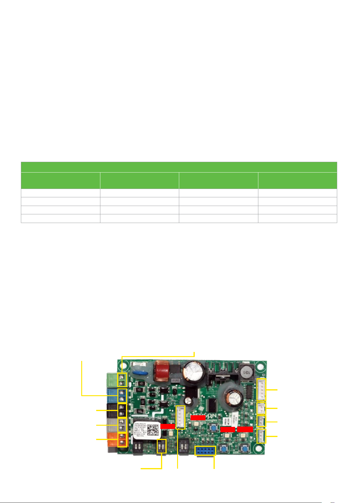
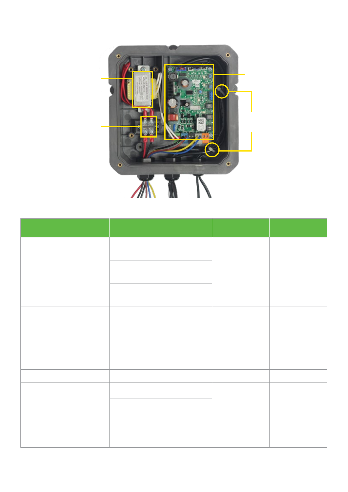
Printed circuit board
Wear a ground strap when working with the PCB to avoid the risk of damage from static discharges.
General PCB layout, input and output ports are shown in the image below, the ports to EXV, DLT, as well as the vapor in and
vapor out sensors are done with Poka-yoke connector design. Connect sensors, EXV, and system wiring as shown in wiring
diagram.
The PCB is supplied power through a transformer with a power input of 50/60 Hz, 220VAC, and an output of 12VAC to the PCB
board.
For EVI control kits with CoreSense box, the board and transformer are both mounted in the box, using 4 x Ø5mm holes at
61 x 101mm centers, fastened by screws. Spare part number is 543-0189-01 for field service.
For EVI control kits without CoreSense box, we provide individual parts for compact system design. The board is with 4 x Ø4mm
holes at 61 x 101mm centers, please use plastic stakes provided. Spare part number is 543-0219-01 for field service.
Compressor start/stop input signal
(from LP switch/cold room temp sensor)
(220 VAC)
Reserved
Compressor
contactor
Dry contact alarm output
terminal
SW1 SW2 SW3
Dip-switch
Board power supply input terminals
(from 12 VAC transformer)
LED 1
LED 4
Programming
ports
Communication ports
LED 2
LED 3
EXV driver
output ports
DLT sensor
input ports
Vapor in sensor
input ports
Vapor out sensor
input ports
19
Page 20

Dip-switch setting
The dip-switch default setting has been done in-factory, please do not change setting and ensure that the replacement board
is set correctly.
For the glide-refrigerants application like R407A, R407F, R407C, we would recommend 10K superheat. Please contact your
local Emerson sales and application engineer to reset the dip-switch.
Dip-switch default factory setting
SW1 SW2 SW3
BIT1 ON OFF OFF
BIT2 ON OFF ON
Dip-switch
Setting position
Function description of
default setting
1 2
O
N
1. Discharge Line Temperature (DLT) control target ≤110°C
2. Vapor out superheat target is 5K
3. Compressor will shut down If DLT above 125°C
4. Compressor can auto-reset and no lockout due to DLT overheat protection
5. Compressor minimum stop time is 0 minute
6. Vapor injection mode
O
N
1 2
O
N
LED functions
LED1 (yellow-green)
LED1 will light up during initialization after power on, after that, blinking lights will indicate the sensor status.
LED Color Compressor or sensor status LED1 behavior
Idle compressor waiting to start Blinks at 1 Hz
1 2
DLT overheat protection Blinks 2 times at 1 Hz, waiting 5s, then repeat…
LED1
LED2, LED3 (yellow-green)
LED2 and LED3 will blink once when entering or exiting EXV manual operation, and also indicate EXV opening and closing.
LED Color EXV status LED2, LED3 behavior
LED2
LED3
20
Yellow-
Green
Yellow-
Green
DLT failure Blinks 3 times at 1 Hz, waiting 5s, then repeat…
Vapor in sensor failure Blinks 4 times at 1 Hz, waiting 5s, then repeat…
Vapor out sensor failure Blinks 5 times at 1 Hz, waiting 5s, then repeat…
Opening LED2 is flashing at 1 Hz, LED3 off
Closing LED3 is flashing at 1 Hz, LED2 off
Fully open LED2 constant on, LED3 off
Fully closed LED3 constant on, LED2 off
Page 21
LED4 (red color) alarm
LED4 will turn on when alarm is triggered by the following items
LED Color Sensor status LED4 behavior
DLT overheat protection LED4 on, red color
LED4 Red
DLT sensor failure LED4 on, red color
Vapor in sensor failure LED4 on, red color
Vapor out sensor failure LED4 on, red color
Temperature sensors
The EVI kits include 3 temperature sensors. Please ensure all sensors are mounted in the correct locations, fastened, and
insulated properly.
The discharge temperature sensor should be installed approximately 178mm (7 inches) from discharge tube outlet. If a service
valve is installed at the discharge tube, the sensor should be located 127mm (5 inches) from the valve braze.
The vapor-in sensor is connected to the pipe between the EXV and PHE. The vapor-out sensor is connected to the pipe from
the PHE to the compressor vapor injection port. Don’t make the vapor-in and vapor-out sensor location reversed.
Sensor Wire length Resistance value vs. temperature Open Short
Discharge
temperature
sensor
Vapor-in
sensor
Vapor-out
sensor
930mm or
1800mm
1360mm or
1800mm
750mm or
1800mm
351.6 kΩ @0°C
100.0 kΩ @25°C
5.8 kΩ @100°C
28.1 kΩ @0°C
10.0 kΩ @25°C
0.9 kΩ @100°C
28.1 kΩ @0°C
10.0 kΩ @25°C
0.9 kΩ @100°C
>1000kΩ <400Ω
>500kΩ <500Ω
>500kΩ <500Ω
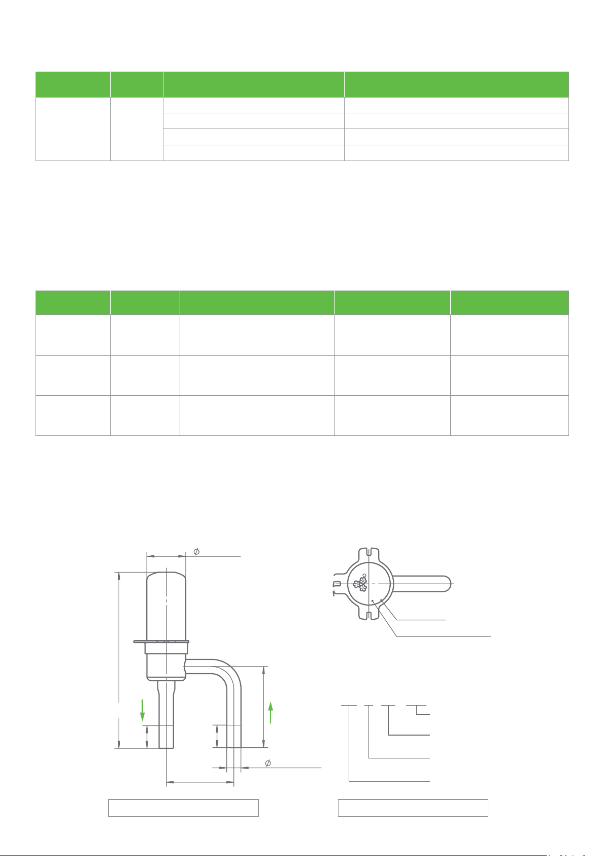
Electronic expansion valve (EXV)
The EXV contains an EXV-valve and EXV-coil, lead wire length for coil is 1796mm, the valve size includes Ø1.3mm, Ø1.65mm
and Ø1.8mm depending on system size, applied to different ZFI models.
The liquid refrigerant should pass from the bending tube and flow out from the straight tube. Please weld the filter before the
EXV provided along with the kits.
17.35max
13829001
10C311ST
R
Production lot
Product identification code
87 3±
Liquid out
EXV valve connection size, mm EXV valve identification code
Product identification code specific
10 C 31 1ST
Liquid in
63 3±
01
01
×2 53.6 1.0±
03 3±
Optional design
Refrigerant
Valve orifice
Product series
21
Page 22
ZFI standard control box wiring example
Transformer
Terminal
Waterproof
gland no.
Wire function
Wire connection
1 2 3
A B C D E F
Gland 1 Gland 2 Gland 3
A (red) and B (black):
Controller power supply input
(220–240 VAC 50/60 Hz)
C (black) and D (brown):
Compressor start/stop input
(220–240 VAC 50/60 Hz)
E (blue) and F (yellow):
Compressors contactor coil
Control output
Wires A and B:
Connect to terminal
Wires C and D:
Connect to the blue connector on the
control board
Wires E and F:
Connect to the gray connector
on the control board
Control board
Cables fixed
by ribbon
EXV Coil
DLT Sensor
Connect to the
EXV, DLT sensor at
the top edge of the
control board
Vapor-in sensor
Vapor-out sensor
Connect to the
vapor-in/out port at
the top edge of the
control board
Gland internal diameter range 2–3 mm
Jacket line requirement
22
Internal wire size:
18 AWG
Rated voltage:
300 V/600 V
Rated temperature:
80/105 °C
Recommended:
UL105, UL1011, UL1007
Page 23
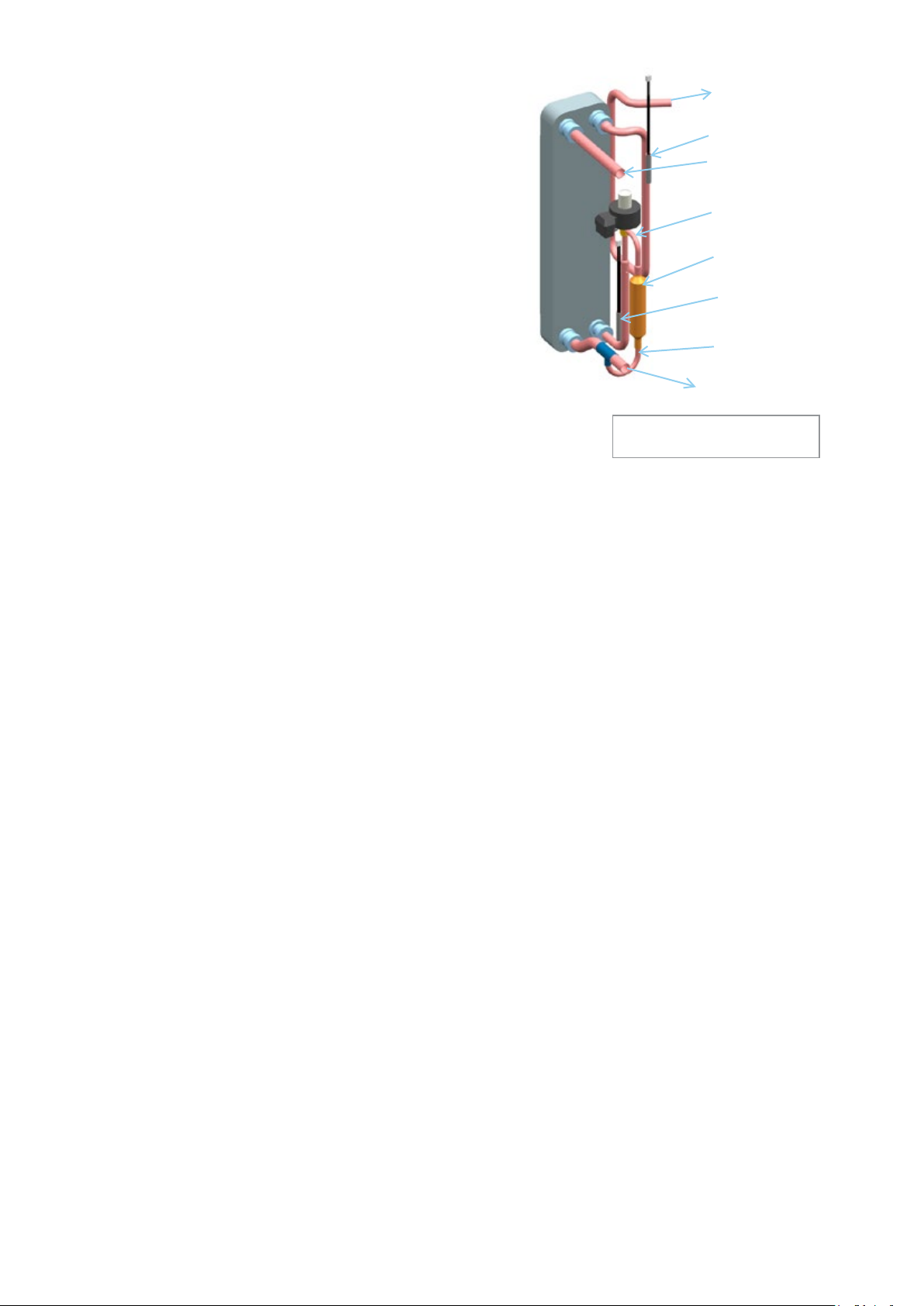
Plate heat exchanger (PHE) and
liquid line temperature
Vapor-out
to compressor
Mount plate heat exchanger in the vertical position and
oriented correctly. Ensure that sensors are located correctly
as well.
ZFI vapor injection compressors can deliver very cold liquid
with economizer cycle. The sub-cooling of liquid line calls for
these recommendations:
1. Liquid line pipe connecting the economizer to the
evaporator expansion valve should be well-insulated
separately.
2. The lower liquid line temperature can increase the
evaporator valve capacities. Please follow the valve
manufacturer's recommended liquid temperature
correction factors for proper selection of evaporator
expansion valve. Refer to product catalogue or select
software for liquid line temperature.
Vapor-out sensor
Liquid-in
Liquid-in
to EXV side
Filter
Vapor-in sensor
EXV liquid
supply
Liquid-out
Example of PHE assembly with
downstream liquid supply
23
Page 24
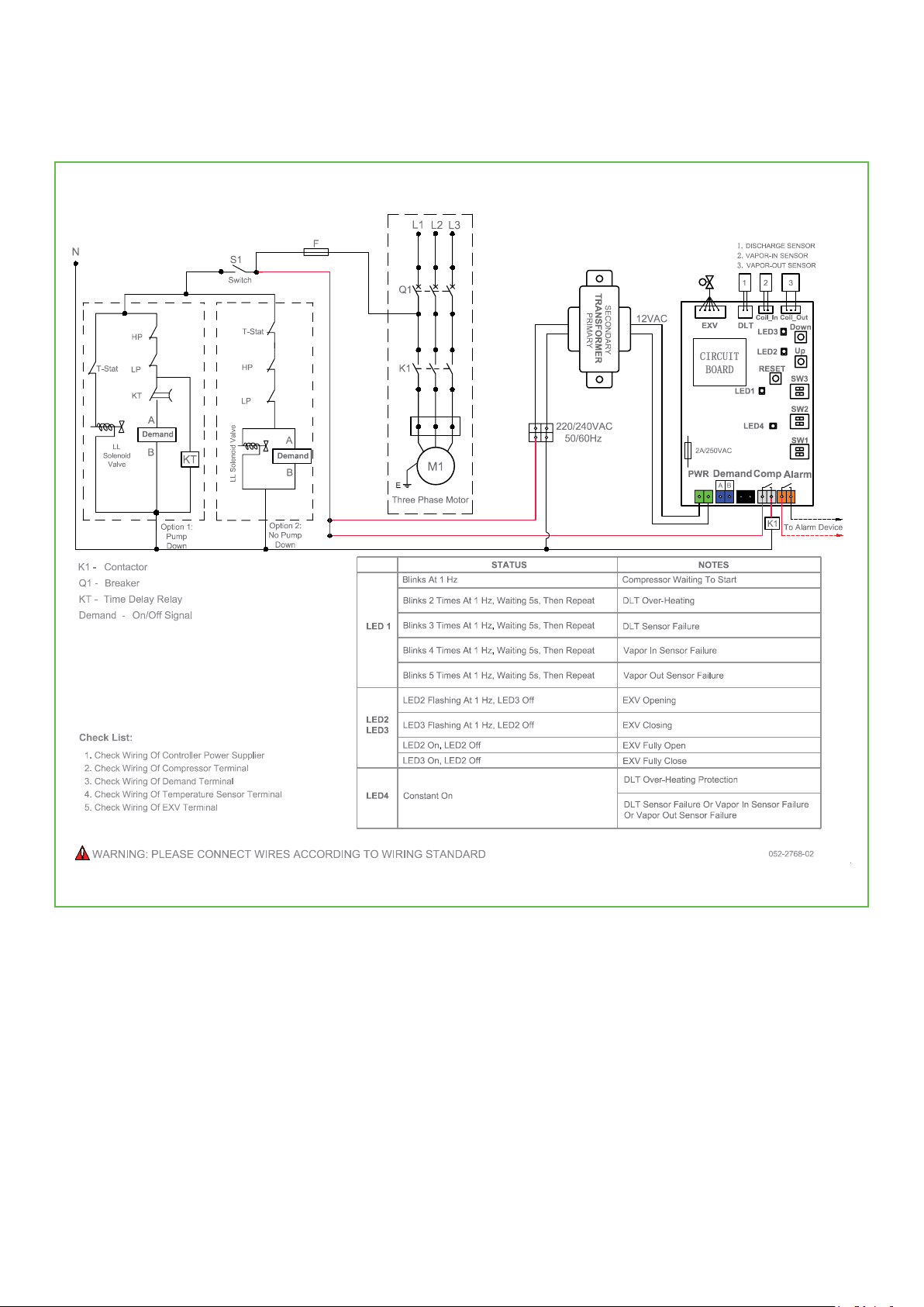
Wiring diagram
ZFI 20 - ZFI81
24
Page 25
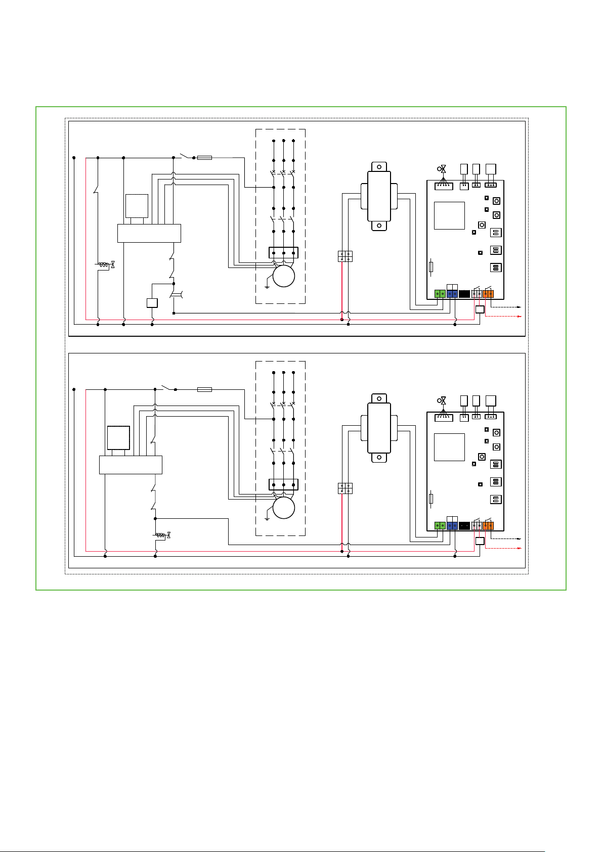
ZFI 122
Wiring Diagram (Pump Down)
N
Wiring Diagram (No Pump Down)
N
T-Stat
To DPT
Sensor
T1
CoreSense Module P47
T2
LL
Solenoid
Valve
To DPT
Sensor
T1
T2
L3L2L1
CoreSense Module P47
Discharge Sensor
EXV
控制板
CIRCUIT
CIRCUIT
BOARD
2A/250VAC
EXV DLT
CIRCUIT
BOARD
2A/250VAC
PWR
1.
2.
3.
DLT
LED1
DemandPWR
A B
1.
2.
3.
LED1
Demand
B
A
Vapor-in Sensor
Vapor-out Sensor
1
2 3
Coil_In Coil_Out
LED3
LED2
RESET
LED4
Comp
K1
Discharge Sensor
Vapor-in Sensor
Vapor-out Sensor
1
2 3
Coil_In
LED3
LED2
RESET
LED4
Comp
K1
Down
Up
SW3
SW2
SW1
Alarm
To Alarm Device
Coil_Out
Down
Up
SW3
SW2
SW1
Alarm
To Alarm Device
L1
L2
L3
S1
F
L3L2L1
Switch
M1
Q1
K1
M2
HP
M1
E
Three Phase Motor
L1
L2
L3
Q1
K1
KT
T-Stat
M1
S1
Switch
LP
KT
F
M2
HP
LP
LL Solenoid Valve
M1
E
Three Phase Motor
220VAC
50/60Hz
220VAC
50/60Hz
TRANSFORMER
SECONDARY
PRIMARY
TRANSFORMER
SECONDARY
PRIMARY
12VAC
12VAC
25
Page 26

Dimensional drawings
ZF06KQE - ZF11KQE (BOM 551)
Rotalock connection
Model number
mm[in]
A±3.0 B C D±3.0 E F G
ZF06KQE
ZF08KQE
ZF09KQE
ZF11KQE
Notes:
(1) All tolerances ± 1.5mm [0.06in] unless otherwise specified
(2) Due to accumulated assembly tolerances, the listed components may vary from the mounting holes. All fittings: ± 3.0mm [0.12in]
(3) Tube ends must be plugged
(4) All units are in mm[inch]
368.7
[14.52]
391.3
[15.41]
391.3
[15.41]
405.0
[15.94]
343.1
[13.51]
365.7
[14.40]
365.7
[14.40]
379.4
[14.94]
243.8
[9.60]
263.7
[10.38]
263.7
[10.38]
276.4
[10.88]
202.2
[7.96]
222.1
[8.74]
222.1
[8.74]
234.8
[9.24]
279.4
[11.00]
302.0
[11.88]
302.0
[11.88]
315.7
[12.42]
[2.71]
[2.93]
[2.93]
[2.93]
26
68.9
74.6
74.6
74.6
43.4
[1.70]
49.1
[1.93]
49.1
[1.93]
49.1
[1.93]
Page 27

Dimensional drawings
ZF13KQE - ZF28KQE (BOM 551)
Rotalock connection
Model number
mm[in]
A±3.0 B±3.0
ZF13KQE
442.0
ZF18KQE
ZF25KQE D
ZF28KQE
Notes:
(1) All tolerances ± 1.5mm [0.06in] unless otherwise specified
(2) Due to accumulated assembly tolerances, the listed components may vary from the mounting holes. All fittings: ± 3.0mm [0.12in]
(3) Tube ends must be plugged
(4) All units are in mm[inch]
[17.40]
451.0
[17.76]
409.6
[16.13]
418.6
[16.48]
Discharge
fitting
CZF15KQE
D
27
Page 28

Dimensional drawings
246.0 MAX
250.2
ZFI20KQE - ZFI39KQE (BOM 552)
Rotalock connection
[9.69]
122.8
[4.83]
123.1
[9.85]
B
(34º)
26.2
[1.03]
[4.85]
95.3
[3.75]
190.5
[7.50]
95.3
126.9
[3.75]
[5.00]
THERMOSTAT
TUBE
190.5
[7.50]
[9.69]
246.0 MAX
122.8
[4.80]
Ø K
(PIN CIRCLE)
47.6
[1.87]
241.2
[9.50]
(31º)
76.2
[3.00]
ØA THREAD ROTALOCK
SPUD DISCHARGE
31.75[1.25-12] THREAD
ROTALOCK SPUD
SUCTION
Ø 185.5
[7.30]
SIGHT GLASS
PER BOM
OIL DRAIN
12.7
[0.75]
[0.50]
(ROTALOCK)
DETAIL
19.1
VAPOR INJECTION FITTING
(BRAZED) [0.50 I.D.]
VAPOR INJECTION FITTING
[1.00-14 UNS-2A] THREADS
PER BILL OF MATERIAL
FOOT
OR
29º
(44º)
VAPOR INJECTION FITTING
(ROTALOCK)
[1.00-14 UNS-2A] THREADS
PER BOM
A
409.6±3.0
[16.13±0.11]
340.9
[13.42]
296.7±3.0
[11.68±0.11]
233.2±3.0
[9.18±0.11]
79.6
[3.13]
SEE DETAIL
Model number
FOOT
ZFI20KQE
ZFI26KQE
mm[in]
A±3.0 B
442.0
[17.40]
409.6
[16.13]
Discharge
fitting
C
ZFI36KQE D
ZFI39KQE
451.0
[17.76]
Notes:
(1) All tolerances ± 1.5mm [0.06in] unless otherwise specified
(2) Due to accumulated assembly tolerances, the listed components may vary from the mounting holes. All fittings: ± 3.0mm [0.12in]
(3) Tube ends must be plugged
(4) All units are in mm[inch]
418.6
[16.48]
D
28
Page 29

Dimensional drawings
ZF34KQE - ZF54KQE (BOM 564/567)
Rotalock connection
Model number
mm[in]
A B C D E F G
ZF34KQE
ZF41KQE
ZF49KQE
ZF54KQE
Notes:
(1) All tolerances ± 1.5mm [0.06in] unless otherwise specified
(2) Due to accumulated assembly tolerances, the listed components may vary from the mounting holes. All fittings: ± 3.0mm [0.12in]
(3) Tube ends must be plugged
(4) All units are in mm[inch]
533.6
[21.0]
551.5
[21.7]
501.8
[19.75]
519.5
[20.45]
277.3
[10.91]
295.0
[11.61]
245.7
[9.67]
263.6
[10.37]
93.0
[3.66]
92.6
[3.64]
93.0
[3.66]
92.6
[3.64]
393.3
[15.49]
441.0
[16.18]
29
Page 30

Dimensional drawings
ZFI50KQE - ZFI81KQE (BOM 564/567)
Rotalock connection
Model number
mm[in]
A B C D E F G
ZFI50KQE
ZFI59KQE
ZFI68KQE
ZFI81KQE
Notes:
(1) All tolerances ± 1.5mm [0.06in] unless otherwise specified
(2) Due to accumulated assembly tolerances, the listed components may vary from the mounting holes. All fittings: ± 3.0mm [0.12in]
(3) Tube ends must be plugged
(4) All units are in mm[inch]
533.6
[21.01]
551.5
[21.71]
501.8
[19.76]
519.5
[20.45]
393.3
[15.48]
411.0
[16.18]
277.3
[10.92]
295.0
[11.61]
163.3
[6.43]
163.3
[6.43]
93.0
[3.66]
92.6
[3.64]
30
93.0
[3.66]
92.6
[3.64]
ØK
17.45
[0.687]
20.70
[0.815]
Page 31

Dimensional drawings
ZF06KQE - ZF11KQE (BOM 550)
Stub tube connection
Model number
mm[in]
A B C D E F G
ZF06KQE
ZF08KQE
ZF09KQE
ZF11KQE
Notes:
(1) All tolerances ± 1.5mm [0.06in] unless otherwise specified
(2) Due to accumulated assembly tolerances, the listed components may vary from the mounting holes. All fittings: ± 3.0mm [0.12in]
(3) Tube ends must be plugged
(4) All units are in mm[inch]
369.9
[14.56]
392.5
[15.45]
406.3
[16.00]
343.8
[13.54]
366.4
[14.42]
380.1
[14.96]
28O.O
[11.O2]
302.6
[11.91]
316.4
[12.46]
244.5
[9.62]
264.4
[10.41]
277.1
[10.91]
202.9
[7.99]
222.8
[8.77]
235.5
[9.27]
69.6
[2.74]
75.3
[2.96]
75.3
[2.96]
44.1
[1.74]
49.8
[1.96]
49.8
[1.96]
31
Page 32
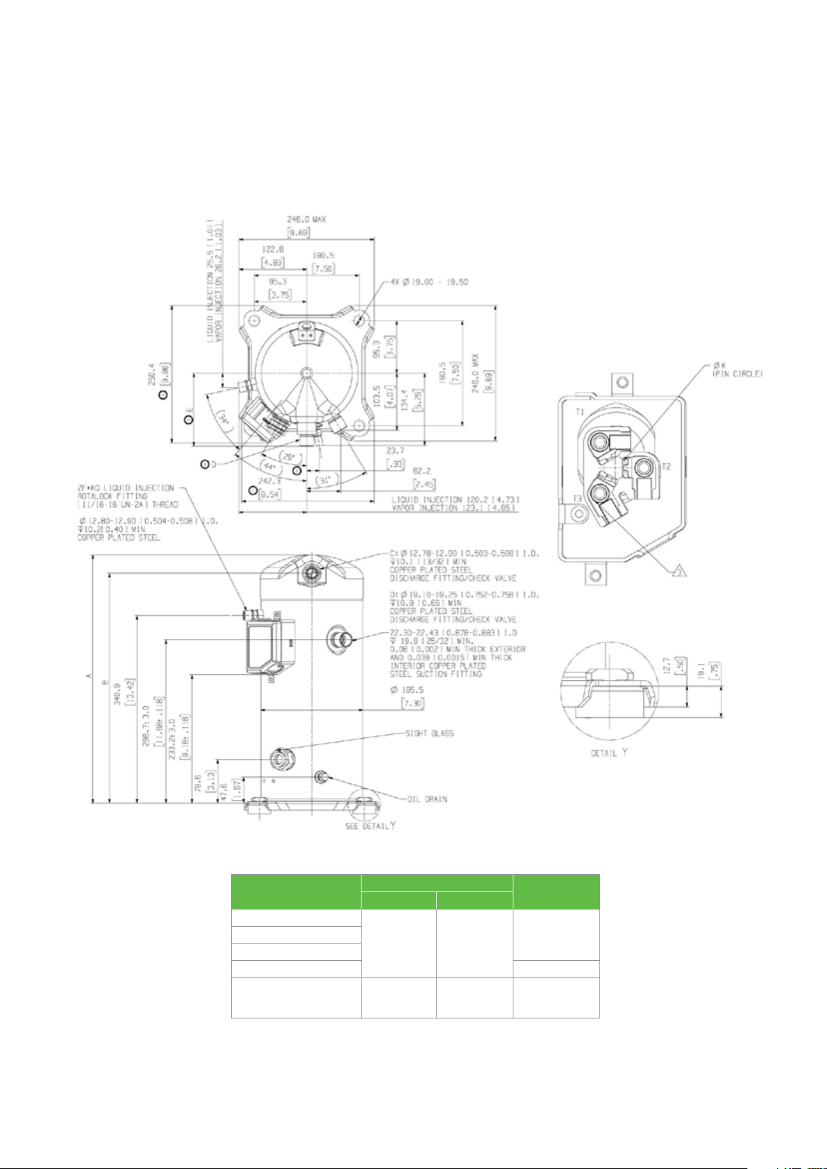
Dimensional drawings
ZF13KQE – ZF28KQE (BOM 550)
Stub tube connection
Model number
ZF13KQE
ZF18KQE
ZF25KQE D
ZF28KQE
Notes:
(1) All tolerances ± 1.5mm [0.06in] unless otherwise specified
(2) Due to accumulated assembly tolerances, the listed components may vary from the mounting holes. All fittings: ± 3.0mm [0.12in]
(3) Tube ends must be plugged
(4) All units are in mm[inch]
mm[in]
A±3.0 B±3.0
442.0
[17.40]
451.0
[17.76]
409.6
[16.13]
418.6
[16.48]
Discharge
fitting
CZF15KQE
D
32
Page 33
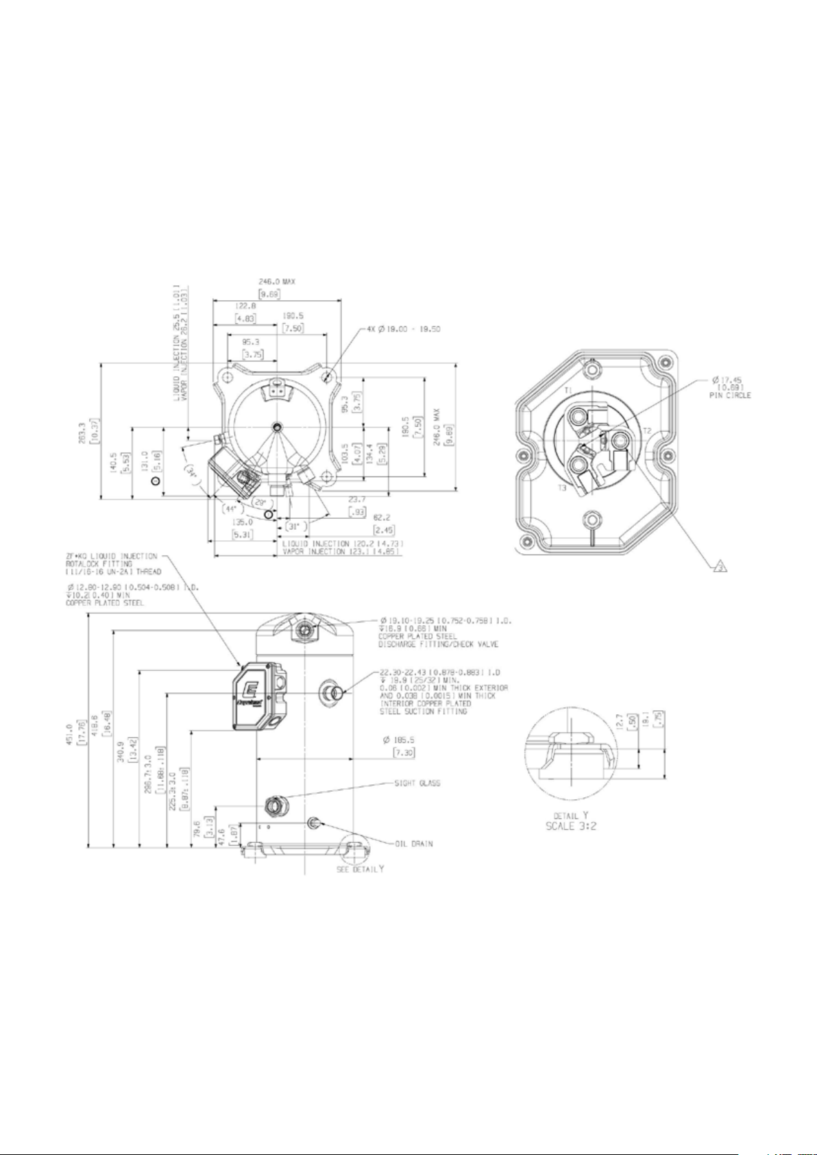
Dimensional drawings
ZF28KQE-TFC and ZFI39KQE-TFC (BOM 580)
Stub tube connection
Notes:
(1) All tolerances ± 1.5mm [0.06in] unless otherwise specified
(2) Due to accumulated assembly tolerances, the listed components may vary from the mounting holes. All fittings: ± 3.0mm [0.12in]
(3) Tube ends must be plugged
(4) All units are in mm[inch]
33
Page 34
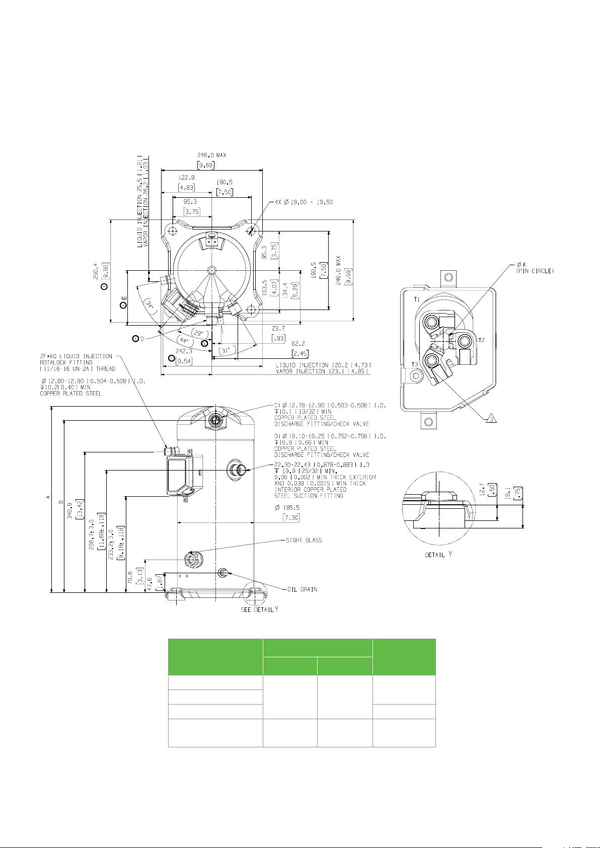
Dimensional drawings
ZFI20KQE – ZFI39KQE (BOM 550)
Stub tube connection
Model number
mm[in]
A±3.0 B
ZFI20KQE
ZFI26KQE
ZFI36KQE D
ZFI39KQE
Notes:
(1) All tolerances ± 1.5mm [0.06in] unless otherwise specified
(2) Due to accumulated assembly tolerances, the listed components may vary from the mounting holes. All fittings: ± 3.0mm [0.12in]
(3) Tube ends must be plugged
(4) All units are in mm[inch]
442.0
[17.40]
451.0
[17.76]
409.6
[16.13]
418.6
[16.48]
Discharge
fitting
C
D
34
Page 35

Dimensional drawings
ZF34KQE – ZF41KQE (BOM 554)
Stub tube connection
Notes:
(1) All tolerances ± 1.5mm [0.06in] unless otherwise specified
(2) Due to accumulated assembly tolerances, the listed components may vary from the mounting holes. All fittings: ± 3.0mm [0.12in]
(3) Tube ends must be plugged
(4) All units are in mm[inch]
35
Page 36
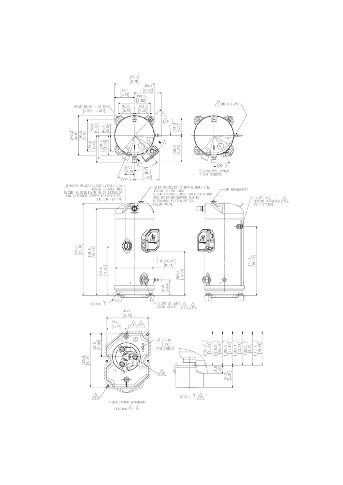
Dimensional drawings
ZF49/54KQE-TFD/TF7 (BOM 554)
Stub tube connection
Notes:
(1) All tolerances ± 1.5mm [0.06in] unless otherwise specified
(2) Due to accumulated assembly tolerances, the listed components may vary from the mounting holes. All fittings: ± 3.0mm [0.12in]
(3) Tube ends must be plugged
(4) All units are in mm[inch]
36
Page 37
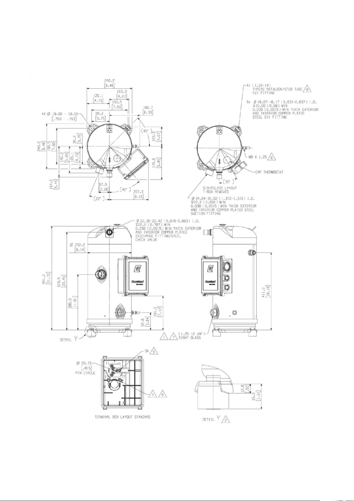
Dimensional drawings
ZF49/54KQE-TFC and ZFI68/81KQE-TFC (BOM 554)
Stub tube connection
Notes:
(1) All tolerances ± 1.5mm [0.06in] unless otherwise specified
(2) Due to accumulated assembly tolerances, the listed components may vary from the mounting holes. All fittings: ± 3.0mm [0.12in]
(3) Tube ends must be plugged
(4) All units are in mm[inch]
37
Page 38
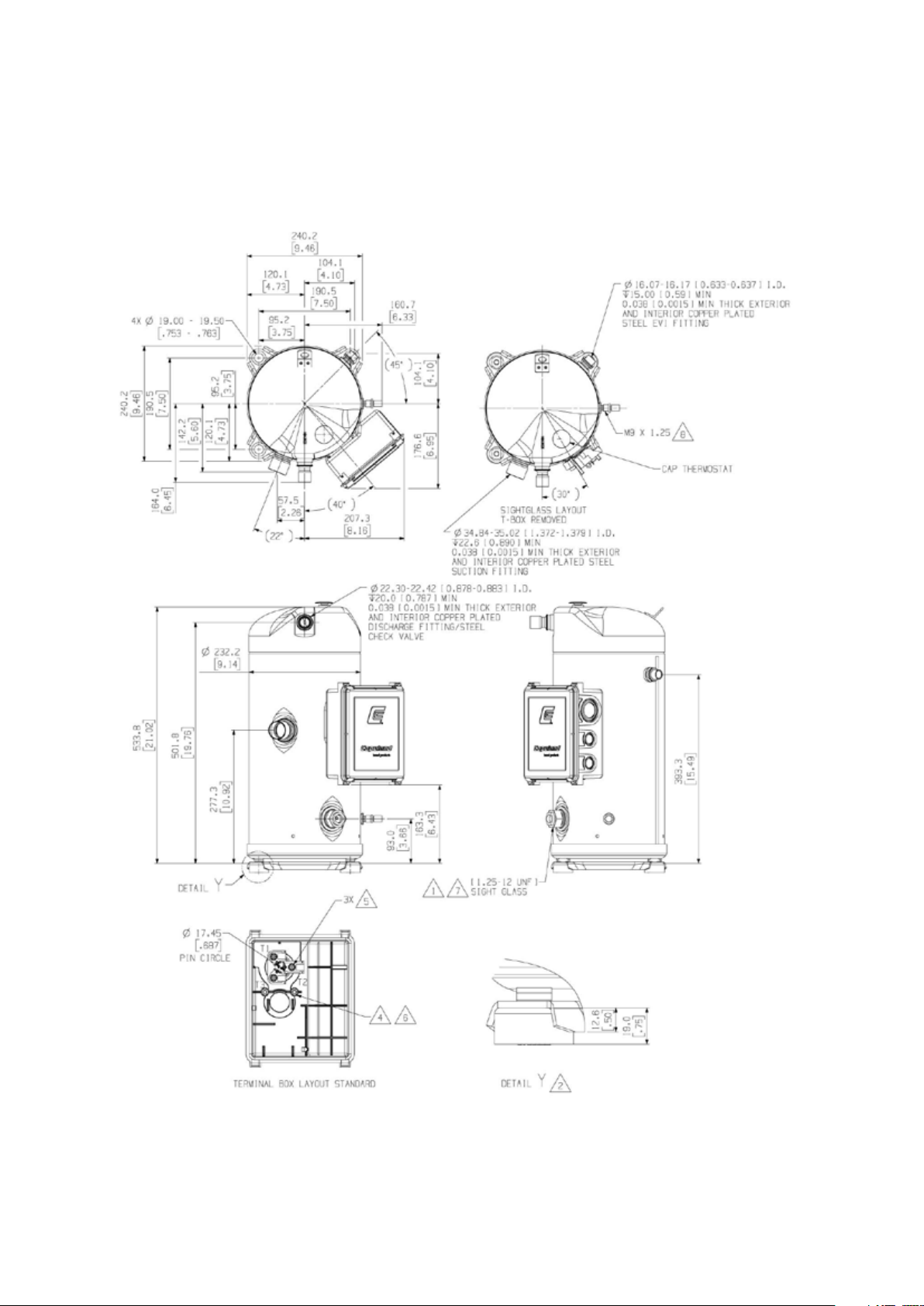
Dimensional drawings
ZFI50KQE – ZFI59KQE (BOM 554)
Stub tube connection
Notes:
(1) All tolerances ± 1.5mm [0.06in] unless otherwise specified
(2) Due to accumulated assembly tolerances, the listed components may vary from the mounting holes. All fittings: ± 3.0mm [0.12in]
(3) Tube ends must be plugged
(4) All units are in mm[inch]
38
Page 39
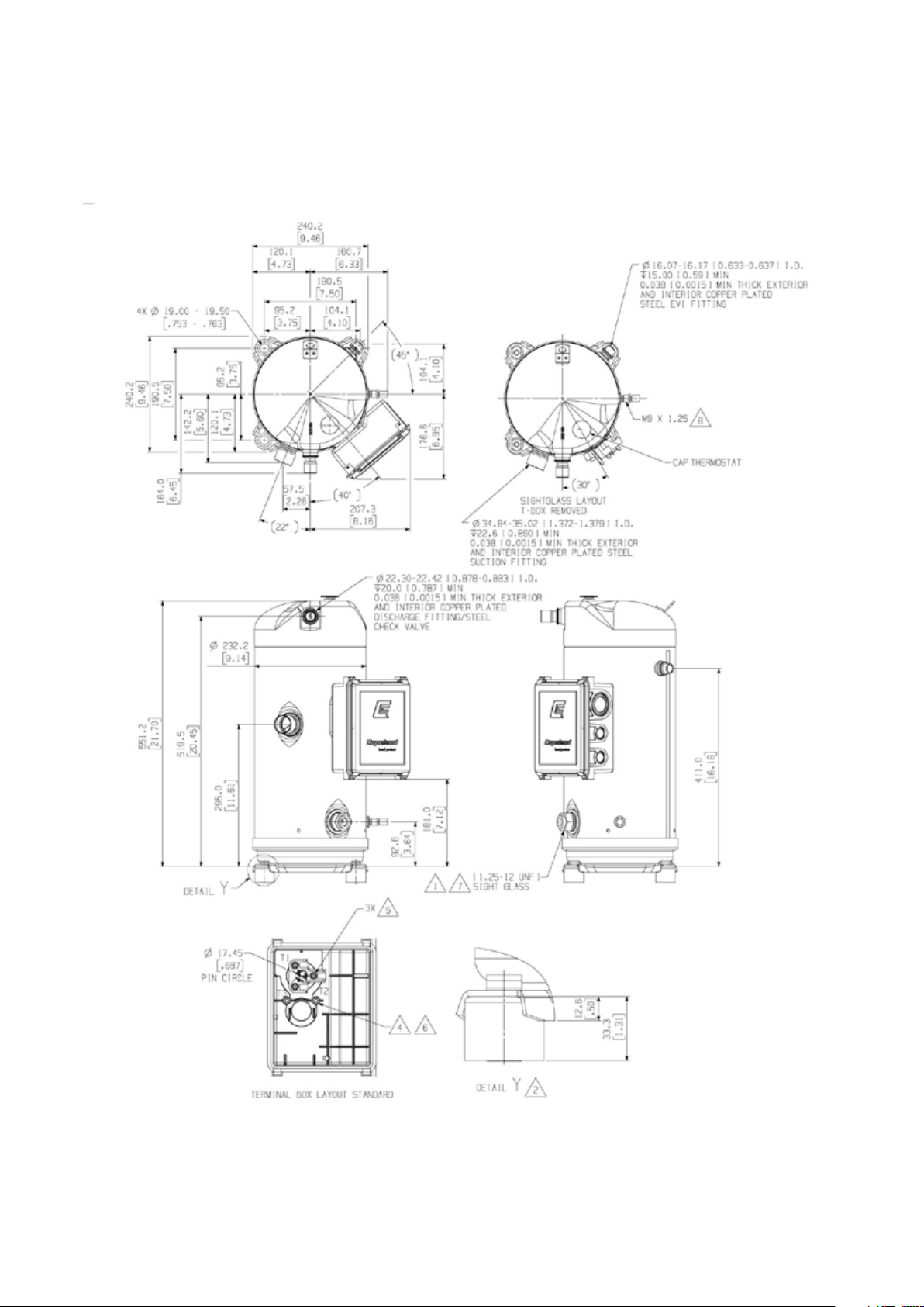
Dimensional drawings
ZFI68/81KQE–TFD/TF7 (BOM 554)
Stub tube connection
Notes:
(1) All tolerances ± 1.5mm [0.06in] unless otherwise specified
(2) Due to accumulated assembly tolerances, the listed components may vary from the mounting holes. All fittings: ± 3.0mm [0.12in]
(3) Tube ends must be plugged
(4) All units are in mm[inch]
39
Page 40
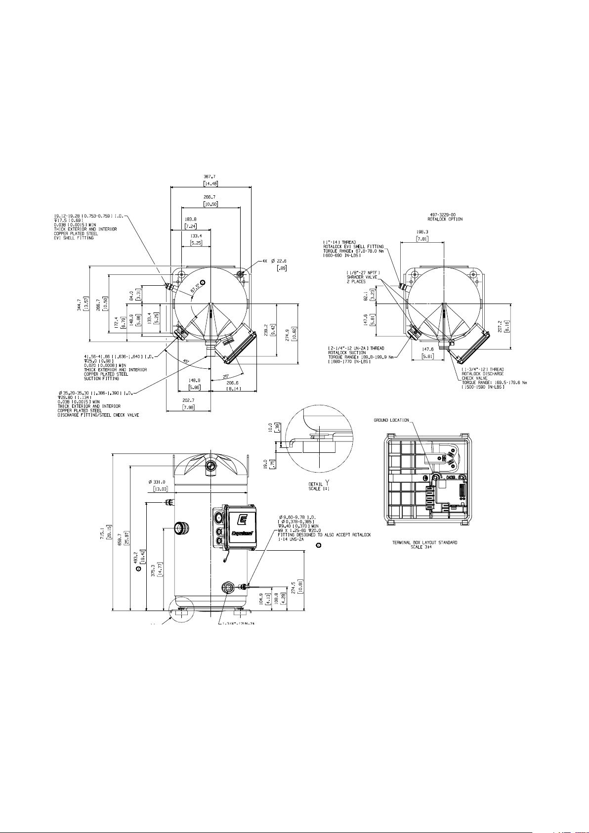
Dimensional drawings
ZFI122KQE - TED/TE7/TEC (BOM 522/523)
Stub tube / Rotalock connection
Notes:
(1) All tolerances ± 1.5mm [0.06in] unless otherwise specified
(2) Due to accumulated assembly tolerances, the listed components may vary from the mounting holes. All fittings: ± 3.0mm [0.12in]
(3) Tube ends must be plugged
(4) All units are in mm[inch]
40
Page 41
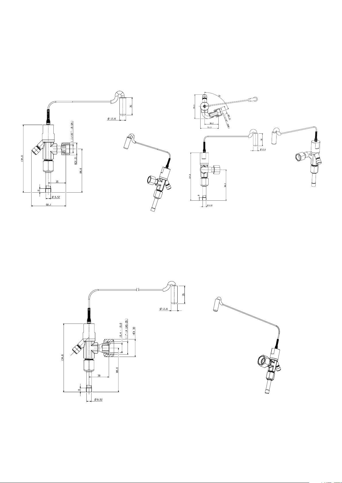
Dimensional drawings
DTC Valve prints
ZF06-28
ZF34-54
Note: Unit is mm
41
Page 42

Dimensional drawings
CoreSense module
ZFI20 - ZFI122
Note: Unit is mm
42
Page 43

Schematic diagram
Condensing Unit
Liquid injection schematic
Condenser
DLT Sensor
ZF
ZF
ZFI
Oil
Separator
Vapor injection schematic
DTC Valve
Sight
Glass
Evaporator
Filter
Receiver
TXV
Filter Drier
Sight
Glass
s
Liquid Line
Solenoid Valve
Unit Cooler
DLT sensor
Oil
separator
ZFI
EVI
CoreSense™
control
EXV
Condenser
Receiver
Sight glass
PHE*
s
Solenoid
valve
Condensing unit
Filter drier
Filter
Sight
glass
*PHE: Plate heat exchanger
Evaporator
TXV
s
Liquid line
solenoid valve
Unit cooler
43
Page 44

Available models – ZF Liquid injection
Model
TFD
380-420V-3ph-50 Hz ;
460V-3ph-60 Hz
TF5
200-220V-3ph-50 Hz ;
200-230V-3ph-60 Hz
TFC
200V-3ph-50 Hz ;
208-230V-3ph-60 Hz
TF7
380V-3ph-60 Hz
PFV
200V-1ph-50 Hz ;
208-230V-1ph-60 Hz
ZF Liquid injection models
Rotalock Stub tube Manufacturing plant Status
ZF06KQE-TFD-551 ZF06KQE-TFD-550 Thailand Active
ZF08KQE-TFD-551 ZF08KQE-TFD-550 Thailand Active
ZF09KQE-TFD-551 ZF09KQE-TFD-550 Thailand Active
ZF11KQE-TFD-551 ZF11KQE-TFD-550 Thailand Active
ZF13KQE-TFD-551 ZF13KQE-TFD-550 Thailand Active
ZF15KQE-TFD-551 ZF15KQE-TFD-550 Thailand Active
ZF18KQE-TFD-551 ZF18KQE-TFD-550 Thailand Active
ZF25KQE-TFD-551 ZF25KQE-TFD-550 Thailand Active
ZF28KQE-TFD-551 ZF28KQE-TFD-550 Thailand Active
ZF34KQE-TFD-564 ZF34KQE-TFD-554 Thailand Active
ZF41KQE-TFD-564 ZF41KQE-TFD-554 Thailand Active
ZF49KQE-TFD-564 ZF49KQE-TFD-554 Thailand Active
ZF54KQE-TFD-564 ZF54KQE-TFD-554 Thailand Active
ZF06KQE-TF5-551 ZF06KQE-TF5-550 Thailand Active
ZF08KQE-TF5-551 ZF08KQE-TF5-550 Thailand Active
ZF09KQE-TF5-551 ZF09KQE-TF5-550 Thailand Active
ZF11KQE-TF5-551 ZF11KQE-TF5-550 Thailand Active
ZF13KQE-TFC-551 ZF13KQE-TFC-550 Thailand Active
ZF13KQE-TFC-551 ZF13KQE-TFC-550 Thailand Active
ZF15KQE-TFC-551 ZF15KQE-TFC-550 Thailand Active
ZF18KQE-TFC-551 ZF18KQE-TFC-550 Thailand Active
ZF25KQE-TFC-551 ZF25KQE-TFC-550 Thailand Active
ZF28KQE-TFC-591 ZF28KQE-TFC-580 Thailand Active
ZF34KQE-TFC-564 / 567 ZF34KQE-TFC-554 Thailand Active
ZF41KQE-TFC-564 / 567 ZF41KQE-TFC-554 Thailand Active
ZF49KQE-TFC-564 / 567 ZF49KQE-TFC-554 Thailand Active
ZF54KQE-TFC-564 / 567 ZF54KQE-TFC-554 Thailand Active
ZF13KQE-TF7-551 ZF13KQE-TF7-550 Thailand Active
ZF15KQE-TF7-551 ZF15KQE-TF7-550 Thailand Active
ZF18KQE-TF7-551 ZF18KQE-TF7-550 Thailand Active
ZF25KQE-TF7-551 ZF25KQE-TF7-550 Thailand Active
ZF28KQE-TF7-551 ZF28KQE-TF7-550 Thailand Active
ZF34KQE-TF7-564 / 567 ZF34KQE-TF7-554 Thailand Active
ZF41KQE-TF7-564 / 567 ZF41KQE-TF7-554 Thailand Active
ZF49KQE-TF7-564 / 567 ZF49KQE-TF7-554 Thailand Active
ZF54KQE-TF7-564 / 567 ZF54KQE-TF7-554 Thailand Active
ZF06KQE-PFV-551 ZF06KQE-PFV-550 Thailand Active in 2020
ZF08KQE-PFV-551 ZF08KQE-PFV-550 Thailand Active in 2020
ZF09KQE-PFV-551 ZF09KQE-PFV-550 Thailand Active in 2020
ZF11KQE-PFV-551 ZF11KQE-PFV-550 Thailand Active in 2020
ZF13KQE-PFV-551 ZF13KQE-PFV-550 Thailand Active In 2020
ZF15KQE-PFV-551 ZF15KQE-PFV-550 Thailand Active In 2020
Notes: Please select the right BOMs when ZFI50-81 models are used in Rack application (BOM554/564 for OMB and 567 for OM3)
44
Page 45

Available models – ZFI Vapor injection
Model
TFD/TED
380-420V-3ph-50 Hz ;
460V-3ph-60 Hz
TFC/TEC
200V-3ph-50 Hz ;
208-230V-3ph-60 Hz
TF7/TE7
380V-3ph-60 Hz
ZFI Vapor injection models
Rotalock Stub tube Manufacturing plant Status
ZFI20KQE-TFD-552 ZFI20KQE-TFD-550 Thailand Active
ZFI23KQE-TFD-552 ZFI23KQE-TFD-550 Thailand Active
ZFI26KQE-TFD-552 ZFI26KQE-TFD-550 Thailand Active
ZFI36KQE-TFD-552 ZFI36KQE-TFD-550 Thailand Active
ZFI39KQE-TFD-552 ZFI39KQE-TFD-550 Thailand Active
ZFI50KQE-TFD-564 / 567 ZFI50KQE-TFD-554 Thailand Active
ZFI59KQE-TFD-564 / 567 ZFI59KQE-TFD-554 Thailand Active
ZFI68KQE-TFD-564 / 567 ZFI68KQE-TFD-554 Thailand Active
ZFI81KQE-TFD-564 / 567 ZFI81KQE-TFD-554 Thailand Active
ZFI122KQE-TED-523 ZFI122KQE-TED-522 Suzhou, China Active
ZFI20KQE-TFC-552 ZFI20KQE-TFC-550 Thailand Active
ZFI23KQE-TFC-552 ZFI23KQE-TFC-550 Thailand Active
ZFI26KQE-TFC-552 ZFI26KQE-TFC-550 Thailand Active
ZFI36KQE-TFC-552 ZFI36KQE-TFC-550 Thailand Active
ZFI39KQE-TFC-592 ZFI39KQE-TFC-580 Thailand Active
ZFI50KQE-TFC-564 / 567 ZFI50KQE-TFC-554 Thailand Active
ZFI59KQE-TFC-564 / 567 ZFI59KQE-TFC-554 Thailand Active
ZFI68KQE-TFC-564 / 567 ZFI68KQE-TFC-554 Thailand Active
ZFI81KQE-TFC-564 / 567 ZFI81KQE-TFC-554 Thailand Active
ZFI122KQE-TEC-523 ZFI122KQE-TEC-522 Suzhou, China Active
ZFI20KQE-TF7-552 ZFI20KQE-TF7-550 Thailand Active
ZFI23KQE-TF7-552 ZFI23KQE-TF7-550 Thailand Active in 2020
ZFI26KQE-TF7-552 ZFI26KQE-TF7-550 Thailand Active
ZFI36KQE-TF7-552 ZFI36KQE-TF7-550 Thailand Active
ZFI39KQE-TF7-552 ZFI39KQE-TF7-550 Thailand Active
ZFI50KQE-TF7-564 / 567 ZFI50KQE-TF7-554 Thailand Active
ZFI59KQE-TF7-564 / 567 ZFI59KQE-TF7-554 Thailand Active
ZFI68KQE-TF7-564 / 567 ZFI68KQE-TF7-554 Thailand Active
ZFI81KQE-TF7-564 / 567 ZFI81KQE-TF7-554 Thailand Active
ZFI122KQE-TE7-523 ZFI122KQE-TE7-522 Suzhou, China Active
Notes: Please select the right BOMs when ZFI50-81 models are used in Rack application (BOM554/564 for OMB and 567 for OM3)
45
Page 46

General information
Technical data are correct at the time of printing. Updates may occur, and should you need confirmation of a specific
value, please contact Emerson stating clearly the information required.
Emerson cannot be held responsible for errors in capacities, dimensions, etc., stated herein. Products, specifications and
data in this literature are subject to change without notice.
The information given herein is based on data and tests which Emerson believes to be reliable and which are in
accordance with today’s technical knowledge. It is intended for use by persons having the appropriate technical
knowledge and skill, at their own discretion and risk. Our products are designed and adapted for fixed locations. For
mobile applications, failures may occur.
The suitability for this has to be assured from the plant manufacturer, which may include making appropriate tests.
Note:
The components listed in this catalogue are not released for use with caustic, poisonous or flammable substances.
Emerson cannot be held responsible for any damage caused by using these substances.
46
Page 47

Notes
47
Page 48

Contact lists
Asia Pacific Headquarters
Suite No. 2503-10A, 25/F,
Exchange Tower, 33 Wang Chiu Road,
Kowloon Bay, Kowloon, Hong Kong
Tel: (852) 2866 3108
Fax: (852) 2520 6227
Australia
356 Chisholm Road
Auburn NSW 2144, Australia
Tel: (612) 9795 2800
Fax: (612) 9738 1699
China - Beijing
Room 1203-1205,
North Wing Junefield Plaza Central Tower,
No. 10 Xuan Wu Men Wai Street,
XiCheng District, Beijing, PRC
Tel: (8610) 5095 2188
China - Guangzhou
Guangzhou Office
Unit 2202B, 22/F, Leatop Plaza,
32 Zhujiang East Road, Tianhe Dist.,
Guangzhou 510623, PRC
Tel: (8620) 8595 5188
China - Shanghai
Shanghai Sales Office
7F, Emerson Building, 1582 Gumei
Rd, Shanghai, PRC
Tel: (8621) 3338 7333
India - Mumbai
Delphi B-Wing, 601-602, 6th Floor
Central Avenue,
Hiranandani Business Park,
Powai, Mumbai 400076, India
Tel: (9122) 6786 0793
Fax: (9122) 6662 0500
India - Pune
Plot No. 23, Rajiv Gandhi Infotech Park,
Phase - II, Hinjewadi,
Pune 411 057, Maharashtra, India
Tel: (9120) 4200 2000
Fax: (9120) 4200 2099
Indonesia
BSD Taman Tekno 8
Jl. Tekno Widya Blok H10 No 2 & 3
Tangerang Selatan 15314
Indonesia
Tel: (6221) 2966 6242
Fax: (6221) 2966 6245
Japan
Shin-yokohama Tosho Building
No. 3-9-5 Shin-Yokohama, Kohoku-ku
Yokohama 222-0033 Japan
Tel: (8145) 475 6371
Fax: (8145) 475 3565
Malaysia
Level M2, Blk A, Menara PKNS-PJ
Jalan Yong Shook Lin
46050 Petaling Jaya, Selangor, Malaysia
Tel: (603) 7949 9222
Fax: (603) 7949 9333
Middle East & Africa
PO Box 26382
Jebel Ali Free Zone - South
Dubai, UAE
Tel: (9714) 811 8100
Fax: (9714) 886 5465
Philippines
10/F SM Cyber West Avenue, EDSA cor. West
Avenue, Barangay Bungad,
Diliman, Quezon City 1105 Philippines
Tel: (632) 8689 7200
Saudi Arabia
PO Box 34332 - 3620 Building 7874
Unit 1, 67th street 2nd Industrial City
Dammam, Saudi Arabia
Toll Free: 800 844 3426
Tel: +966 3 8147560
Fax: +966 3 8147570
South Korea
3F, The Pinnacle Gangnam
343, Hakdong-ro, Gangnam-gu,
Seoul 06060, Republic of Korea
Tel: (822) 3483 1500
Fax: (822) 592 7883
Taiwan
3F No. 122 Lane 235,
Pao Chiau Rd., XinDianv Dist.,
New Taipei City 23145, Taiwan (R.O.C.)
Tel: (8862) 8912 1360
Fax: (8862) 8912 1890
Thailand
34th Floor, Interlink Tower,
1858/133, Bangna Trad,
Bangkok 10260, Thailand
Tel: (662) 716 4700
Fax: (662) 751 4241
United Arab Emirates
Jebel Ali Free Zone
PO Box 26382
Dubai UAE
Toll Free: 800 441 3428
Tel: +971 4 811 8100
Fax: +971 4 886 5465
Vietnam
Level 6, Melinh Point Tower,
2 Ngo Due Ke,
District 1, Ho Chi Minh City
Vietnam
Tel: (84) 908 009 189
Climate.Emerson.com/Asia
Asia 00 05 Issued 12/2019 Emerson is a trademark of Emerson Electric Co. or one of its affiliated companies.
©2019 Emerson Electric Co. All rights reserved.
Scan to visit:
Emerson Asia
@EmersonComResAP
 Loading...