

Page 1

Copeland Scroll™ Compressor
ZBKQ for Refrigeration Applications
Product Catalogue
1
Page 2

Table of contents
Features and benefits
Nomenclature 05
Bill of material 05
Operating envelopes 06
Product line-up 08
Performance data 09
Technical data 46
Dimensional drawings 49
Electrical wiring diagram 64
Quick application guide 66
03
Available models list 76
Contact list 80
2
Page 3

Emerson is the world’s leading compressor manufacturer
Axial compliance
Radial compliance
Fix
Discharge
and is committed to maximizing system efficiency and
protecting the environment. We offer a wide range of
solutions for commercial refrigeration applications. The
Copeland Scroll™ ZB Compressor is widely recognized in
the refrigeration market for its reliability and low running
cost in high and medium temperature applications. The
newly released ZB large refrigeration scroll compressor
expands the current ZB product line to 30 HP and is
optimized for medium temperature applications for
best-in-class seasonal energy efficiency. ZB refrigeration
scrolls offer customers an excellent solution to replacing
traditional semi-hermetic compressors and lead the
transition to scroll technology.
Dual compliance
Compliance means sealing between the orbiting and
fixed scroll involutes. Dual compliance means the
sealing is on both the axial and radial directions. This
prevents refrigerant leak back across successive scroll
pressure pockets. Compliance design also allows the
scroll involutes to separate in both the radial and axial
directions. This allows debris or liquid refrigerant to
pass through the scroll involutes without damaging the
compressor. Benefits of Dual Compliance are:
• Increased efficiency
• Better liquid handling capability
• Better handling of debris
Features and benefits
Robust and reliable
Copeland Scroll compressors have 70% fewer moving
parts than reciprocating compressors and feature a scroll
Compliance mechanism which makes them particularly
robust and reliable under severe conditions including
liquid slugging.
ed scroll
Suction
Orbiting
scroll
3
Page 4

Scroll wear in
Compactness
The scroll involutes of Copeland scroll compressor wear
in, rather than wear out. So unlike in other compressor
technologies among similar categories, there is no
constant degradation of performance with time due
to wear out.
Lower sound, vibration and pulsation
The compression process in a scroll set is symmetrical and
continuous. This inherently reduces the sound, vibration
and pulsation. This eliminates the need for use of
vibration absorbers and suction or discharge mufflers in
most of the applications. In further, ZB scroll compressors
are engineered to produce smooth sound spectrum
which improves the quality of sound.
Unloaded start
The scroll sets separate at the instant of compressor
shutdown. This allows the scroll set internal pressures
to equalize on compressor stops. In addition to this, the
scroll sets are not engaged at the instant of starting.
Scroll sets engage only after few milliseconds of startup.
This allows easier startup of ZB scroll compressors. Due
to this design feature, typically a start assist kit is not
required even on single phase compressors.
Copeland Scroll have the advantage of light weight and
compactness with small footprint, making them ideal
for the usage in condensing units, compact refrigeration
systems or special process units. Weight and dimensions
for refrigeration equipment is reduced accordingly.
High efficiency all year round
Copeland ZB Scroll is designed for medium-high
temperature refrigeration and process cooling
applications. Motor, scroll and bearing are optimized for
high seasonal efficiency, which helps end user reduce life
cycle cost all year round.
Multiple refrigerants
ZB compressors are approved for R404A, R507, R22,
R134a, R407F, R448A and R449A refrigerants.
DU bearings
A space age bearing material comprising of porous
bronze with PTFE-lead overlay. These bearings are used
in ZB scroll compressors in the scroll drive and main
bearings. DU bearings work with exceptionally low
friction between the load bearing surfaces. In addition,
DU bearings can operate safely for a short time with
loss of lubrication. This situations could happen on
compressor applications due to oil pump out during a
flooded start or heavy oil dilution after a defrost cycle.
2
Crankshaft
1
4
Page 5

Nomenclature
Lubricant
Medium temperature
refrigeration
Base capacity multiplier
K 1000
Blank Mineral oil
E POE oil
Bill of materials
Z B 76 K Q E - T F D - XXX
Scroll family
Base capacity @ MT rating
(Btu/hr)@60 Hz (ARI)
Bill of material
Compressor
model
Motor
code
Generation
BOM
number
Stub tube
connection
Motor voltages
Three-phase motor
T
P Single phase motor
Motor protection
F Internal inherent protection
W External electronic protection
E External enhanced
Electrical codes
50 Hz 60 Hz
J 220-240V 265V
V 200V 208-230V
D 380-420V 460V
7 - 380V
5 200-220V 200-230V
C 200V 208-230V
Rotalock
connection
Oil sight
glass
Schrader
valve
ZB15KQ/E
ZB19KQ/E
ZB21KQ/E
ZB29KQ/E
ZB38KQ/E
ZB45KQ/E
ZB48KQ/E
ZB58KQ/E
ZB66KQ/E
ZB76KQ/E
ZB88KQ
ZB95KQ/E
ZB114KQ/E
ZB130KQ/E TED, TE7, TEC
ZB150KQ/E
ZB190KQ/E
ZB220KQ/E
(1) PFJ is available for ZB15-ZB29 only
(2) PFV is available for ZB15-ZB38 only
TFD, TF5, TF7,
PFV, PFJ
TFD, TF5, TF7
(TW5/7 for
ZB95/114)
TWD,TW7,TWC
558
559
550
551
550
551
522
523
✓ ✓
✓ ✓
✓ ✓ ✓
✓ ✓ ✓
✓ ✓ ✓
✓ ✓ ✓
✓ ✓ ✓
✓ ✓ ✓
5
Page 6
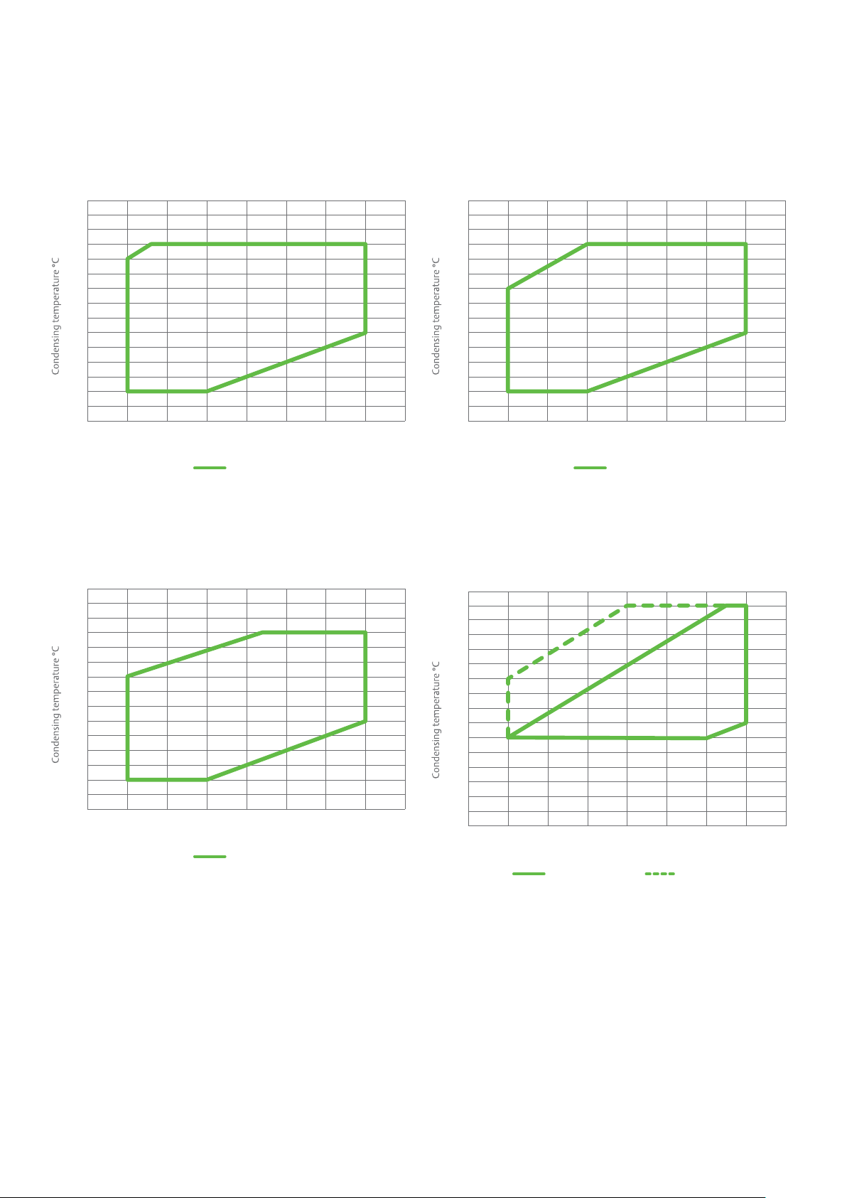
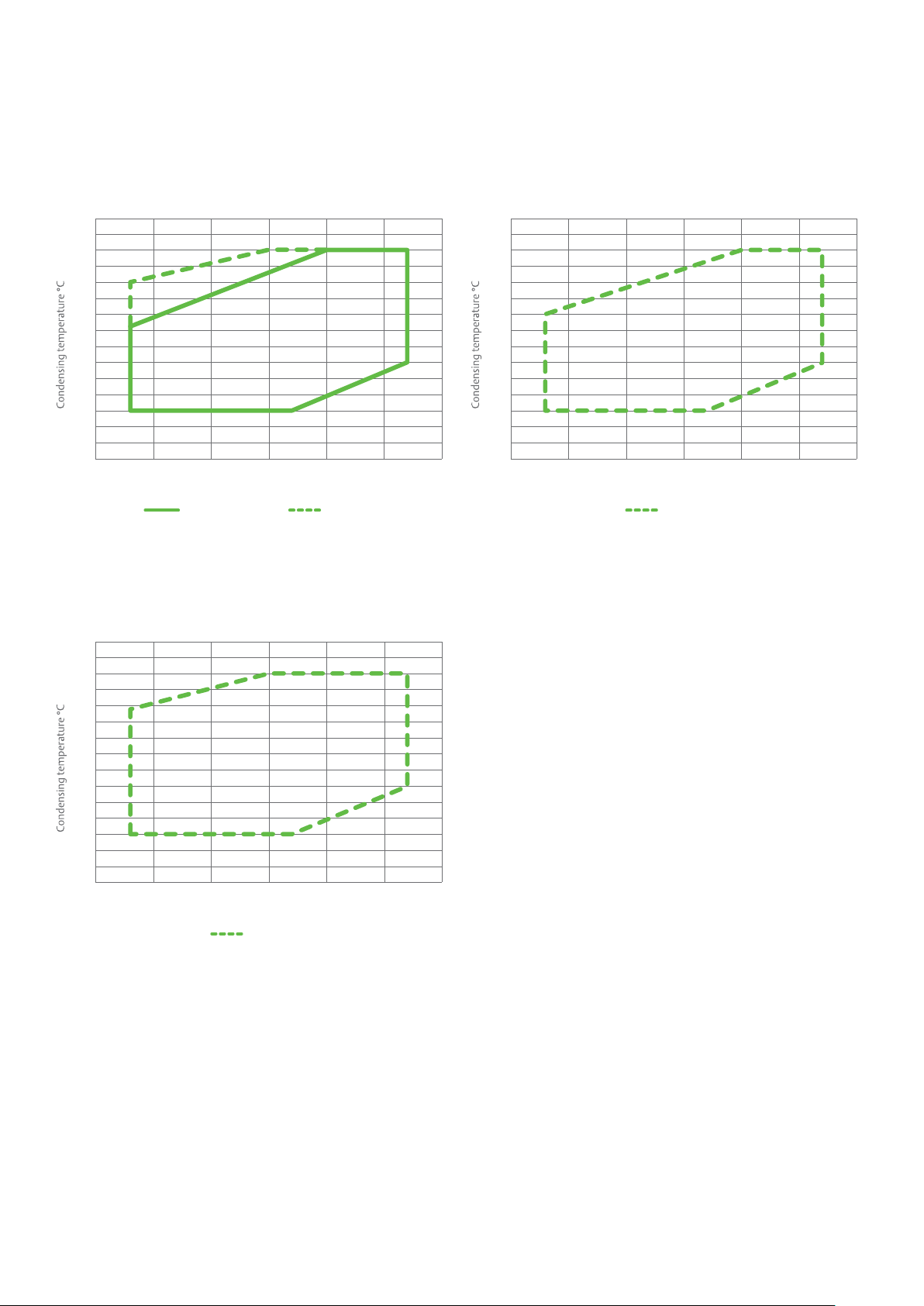
Operating envelopes
0101
R404AZB15KQE~ZB76KQE
20°C Return gas
0101
R404AZB190KQE~ZB220KQE
20°C Return gas
0101
R404AZB95KQE~ZB114KQE, ZB130KQE
20°C Return gas
5152
R134a ZB15KQE~ZB76KQE, ZB130KQE-ZB220KQE
20°C Return gas 11K Superheat
70
65
60
55
50
45
40
35
30
25
20
15
10
5
0
-25
-20 -15 -10 -5 5
Evaporating temperature °C
70
65
60
55
50
45
40
35
30
25
20
15
10
5
0
-25
-20 -15 -10 -5 5
Evaporating temperature °C
5
5
70
65
60
55
50
45
40
35
30
25
20
15
10
5
0
-25
-20 -15 -10 -5 5
Evaporating temperature °C
80
75
70
65
60
55
50
45
40
35
30
25
20
15
10
5
0
-20 -15 -10 -5 010
Evaporating temperature °C
5
0
6
Page 7
Operating envelopes
0101
R22ZB15KQ~ZB88KQ, ZB130KQ-ZB220KQ
20°C Return gas 11K Superheat
R22ZB95KQ~ZB114KQ (TFD only)
11K Superheat
R22ZB95KQ~ZB114KQ (TW7/TW5)
11K Superheat
70
65
60
55
50
45
40
35
30
25
20
15
10
5
0
-15
70
65
60
55
50
45
40
35
30
25
20
15
10
5
0
-15
-10 -5 5
Evaporating temperature °C
-10 -5 0510 15
Evaporating temperature °C
5
70
65
60
55
50
45
40
35
30
25
20
15
10
5
0
-15
-10 -5 0510 15
Evaporating temperature °C
7
Page 8
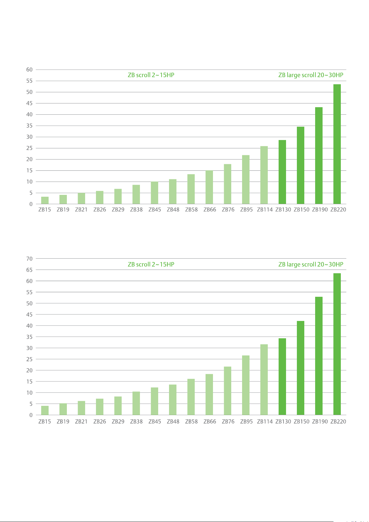
Product line-up
R404A - 50 HzCapacity, kW
Ca
pacity, kW R404A - 60 Hz
Notes: Based on medium temperature cold room conditions: -10°C evaporating, 45°C condensing, 20°C return gas, 0K sub-cooling
8
Page 9

Performance data R22
Q=Capacity (kW) P=Power input (kW) 1-Phase
50 Hz
Model
Q
ZB15KQ
P
Q
ZB19KQ
P
Q
ZB21KQ
P
*20°C Return gas temperature in non-shaded region
*11K Suction superheat in shaded region
*0K Subcooling
Condensing
temperature oC
Evaporating temperature (
o
C)
-12 -10 -5 0 5 10 12.5
15 4.0 4.4 5.3 6.3
20 3.9 4.2 5.1 6.1 7.2
30 3.6 3.9 4.7 5.6 6.7 7.9 8.6
40 3.3 3.5 4.3 5.2 6.1 7.3 7.9
50 2.7 2.9 3.9 4.6 5.5 6.6 7.2
55 2.7 3.4 4.4 5.2 6.2 6.8
60 3.2 3.9 4.9 5.8 6.4
65 3.6 4.5 5.4 5.9
15 0.9 0.9 0.9 0.9
20 1.0 1.0 1.0 1.0 1.0
30 1.2 1.2 1.2 1.2 1.2 1.2 1.2
40 1.4 1.4 1.4 1.4 1.4 1.4 1.4
50 1.7 1.7 1.7 1.7 1.7 1.7 1.7
55 1.9 1.9 1.9 1.9 1.9 1.9
60 2.1 2.1 2.1 2.1 2.1
65 2.4 2.3 2.3 2.3
15 4.7 5.0 6.1 7.3
20 4.5 4.8 5.9 7.0 8.3
30 4.1 4.5 5.4 6.5 7.7 9.1 9.9
40 3.7 4.1 4.9 5.9 7.1 8.4 9.1
50 3.1 3.4 4.4 5.3 6.4 7.6 8.3
55 3.1 3.9 5.0 6.0 7.2 7.8
60 3.6 4.5 5.6 6.7 7.4
65 4.2 5.2 6.3 6.8
15 1.0 1.0 1.0 1.0
20 1.1 1.1 1.1 1.1 1.1
30 1.3 1.3 1.3 1.3 1.3 1.3 1.3
40 1.6 1.6 1.6 1.6 1.6 1.6 1.6
50 1.9 1.9 1.9 1.9 1.9 1.9 1.9
55 2.2 2.1 2.1 2.1 2.1 2.1
60 2.4 2.4 2.4 2.4 2.3
65 2.7 2.6 2.6 2.6
15 5.9 6.3 7.7 9.1
20 5.6 6.1 7.4 8.8 10.5
30 5.2 5.6 6.8 8.2 9.7 11.5 12.5
40 4.7 5.1 6.2 7.5 8.9 10.6 11.5
50 3.9 4.2 5.6 6.7 8.0 9.6 10.4
55 4.0 4.9 6.3 7.6 9.0 9.9
60 4.6 5.7 7.1 8.5 9.3
65 5.2 6.6 7.9 8.6
15 1.4 1.4 1.4 1.4
20 1.5 1.5 1.5 1.5 1.6
30 1.8 1.8 1.8 1.8 1.8 1.9 1.9
40 2.2 2.2 2.2 2.2 2.2 2.2 2.2
50 2.7 2.7 2.7 2.7 2.7 2.7 2.7
55 3.0 3.0 3.0 3.0 3.0 2.9
60 3.3 3.3 3.3 3.3 3.3
65 3.7 3.7 3.6 3.6
9
Page 10

Performance data R22
Q=Capacity (kW) P=Power input (kW) 1-Phase
50 Hz
Model
Q
ZB26KQ
P
Q
ZB29KQ
P
*20°C Return gas temperature in non-shaded region
*11K Suction superheat in shaded region
*0K Subcooling
Condensing
temperature oC
Evaporating temperature (
o
C)
-12 -10 -5 0 5 10 12.5
15 6.8 7.3 8.8 10.5
20 6.5 7.0 8.5 10.2 12.1
30 6.0 6.5 7.9 9.4 11.2 13.3 14.5
40 5.4 5.9 7.2 8.6 10.3 12.2 13.3
50 4.4 4.9 6.4 7.8 9.3 11.0 12.1
55 4.6 5.7 7.3 8.7 10.4 11.4
60 5.3 6.6 8.2 9.8 10.7
65 6.0 7.6 9.1 10.0
15 1.5 1.5 1.5 1.5
20 1.6 1.6 1.6 1.6 1.7
30 1.9 1.9 1.9 2.0 2.0 2.0 2.0
40 2.4 2.4 2.3 2.4 2.4 2.4 2.4
50 2.9 2.9 2.9 2.9 2.9 2.9 2.9
55 3.2 3.2 3.2 3.2 3.2 3.2
60 3.6 3.6 3.5 3.5 3.5
65 4.0 3.9 3.9 3.9
15 7.9 8.6 10.3 12.1
20 7.6 8.3 10.0 11.8 13.8
30 7.0 7.7 9.3 11.1 13.1 15.4 16.7
40 6.4 7.0 8.5 10.2 12.1 14.3 15.6
50 5.4 5.9 7.7 9.2 10.9 13.0 14.3
55 5.7 6.9 8.6 10.3 12.3 13.5
60 6.5 7.8 9.6 11.5 12.7
65 7.4 9.0 10.8 11.8
15 1.6 1.7 1.7 1.8
20 1.8 1.8 1.9 1.9 1.9
30 2.1 2.1 2.2 2.2 2.3 2.3 2.3
40 2.5 2.5 2.6 2.6 2.7 2.7 2.7
50 3.0 3.1 3.1 3.1 3.2 3.2 3.2
55 3.3 3.4 3.4 3.5 3.5 3.5
60 3.7 3.8 3.8 3.8 3.9
65 4.2 4.2 4.2 4.2
10
Page 11

Performance data R22
Q=Capacity (kW) P=Power input (kW) 3-Phase
50 Hz
Model
Q
ZB15KQ
P
Q
ZB19KQ
P
Q
ZB21KQ
P
*20°C Return gas temperature in non-shaded region
*11K Suction superheat in shaded region
*0K Subcooling
Condensing
temperature oC
Evaporating temperature (
o
C)
-12 -10 -5 0 5 10 12.5
15 4.1 4.4 5.3 6.2
20 3.9 4.3 5.1 6.1 7.2
30 3.6 3.9 4.7 5.7 6.7 7.9 8.5
40 3.2 3.5 4.3 5.2 6.1 7.3 7.9
50 2.7 2.9 3.8 4.6 5.5 6.5 7.1
55 2.7 3.4 4.3 5.1 6.1 6.7
60 3.1 3.9 4.8 5.7 6.2
65 3.6 4.4 5.3 5.8
15 0.8 0.8 0.8 0.8
20 0.9 0.9 0.9 0.9 1.0
30 1.1 1.1 1.1 1.1 1.2 1.2 1.2
40 1.4 1.4 1.4 1.4 1.4 1.4 1.4
50 1.7 1.7 1.7 1.7 1.7 1.8 1.7
55 1.9 1.9 1.9 1.9 1.9 1.9
60 2.1 2.1 2.2 2.2 2.2
65 2.4 2.4 2.4 2.4
15 4.7 5.1 6.1 7.2
20 4.5 4.9 5.9 7.0 8.2
30 4.1 4.5 5.5 6.5 7.7 9.1 9.8
40 3.7 4.1 4.9 5.9 7.1 8.4 9.1
50 3.1 3.3 4.4 5.3 6.3 7.5 8.2
55 3.1 3.9 5.0 5.9 7.1 7.7
60 3.6 4.4 5.5 6.6 7.2
65 4.1 5.1 6.1 6.7
15 0.9 0.9 0.9 0.9
20 1.0 1.0 1.0 1.0 1.1
30 1.2 1.2 1.3 1.3 1.3 1.3 1.3
40 1.5 1.5 1.6 1.6 1.6 1.6 1.6
50 1.9 1.9 1.9 2.0 2.0 2.0 2.0
55 2.1 2.2 2.2 2.2 2.2 2.2
60 2.4 2.4 2.5 2.5 2.5
65 2.7 2.7 2.7 2.7
15 5.9 6.4 7.7 9.1
20 5.7 6.2 7.4 8.8 10.4
30 5.2 5.7 6.9 8.2 9.7 11.5 12.4
40 4.7 5.1 6.2 7.5 8.9 10.5 11.5
50 3.8 4.2 5.5 6.7 8.0 9.5 10.3
55 3.9 4.9 6.2 7.5 8.9 9.7
60 4.6 5.6 6.9 8.3 9.1
65 5.2 6.4 7.7 8.4
15 1.2 1.2 1.2 1.2
20 1.3 1.3 1.3 1.4 1.4
30 1.6 1.6 1.6 1.7 1.7 1.7 1.7
40 2.0 2.0 2.0 2.0 2.1 2.1 2.1
50 2.5 2.5 2.5 2.5 2.6 2.6 2.6
55 2.8 2.8 2.8 2.9 2.9 2.9
60 3.1 3.2 3.2 3.2 3.2
65 3.5 3.6 3.6 3.5
11
Page 12

Performance data R22
Q=Capacity (kW) P=Power input (kW) 3-Phase
50 Hz
Model
Q
ZB26KQ
P
Q
ZB29KQ
P
Q
ZB38KQ
P
*20°C Return gas temperature in non-shaded region
*11K Suction superheat in shaded region
*0K Subcooling
Condensing
temperature oC
Evaporating temperature (
o
C)
-12 -10 -5 0 5 10 12.5
15 6.9 7.5 9.0 10.7
20 6.7 7.2 8.7 10.4 12.4
30 6.1 6.7 8.1 9.7 11.6 13.9 15.2
40 5.6 6.1 7.4 8.8 10.6 12.7 14.0
50 4.6 5.1 6.6 7.9 9.5 11.4 12.6
55 4.8 5.9 7.4 8.9 10.7 11.8
60 5.5 6.7 8.3 10.0 11.0
65 6.2 7.7 9.2 10.2
15 1.2 1.2 1.2 1.2
20 1.4 1.4 1.4 1.4 1.4
30 1.7 1.7 1.7 1.7 1.8 1.8 1.7
40 2.2 2.2 2.2 2.2 2.2 2.2 2.2
50 2.8 2.8 2.8 2.8 2.8 2.8 2.7
55 3.2 3.1 3.1 3.1 3.1 3.1
60 3.6 3.6 3.5 3.5 3.4
65 4.0 4.0 3.9 3.9
15 7.9 8.6 10.3 12.2
20 7.6 8.3 9.9 11.8 13.9
30 7.0 7.6 9.2 11.0 13.0 15.4 16.6
40 6.3 6.8 8.3 10.0 11.9 14.1 15.4
50 5.1 5.6 7.4 8.9 10.7 12.7 13.8
55 5.3 6.5 8.4 10.0 11.9 13.0
60 6.1 7.5 9.3 11.1 12.1
65 6.9 8.6 10.3 11.2
15 1.5 1.5 1.5 1.6
20 1.6 1.6 1.7 1.7 1.8
30 2.1 2.0 2.1 2.1 2.2 2.2 2.2
40 2.5 2.5 2.6 2.6 2.6 2.7 2.7
50 3.2 3.2 3.2 3.2 3.3 3.3 3.3
55 3.5 3.6 3.6 3.6 3.7 3.6
60 4.0 4.0 4.1 4.1 4.1
65 4.5 4.5 4.5 4.5
15 9.8 10.6 12.7 15.1
20 9.5 10.2 12.4 14.7 17.3
30 8.7 9.4 11.4 13.7 16.2 19.1 20.7
40 7.8 8.5 10.3 12.4 14.8 17.6 19.1
50 6.4 7.0 9.2 11.1 13.3 15.8 17.2
55 6.5 8.1 10.4 12.4 14.8 16.2
60 7.6 9.3 11.5 13.8 15.1
65 8.6 10.7 12.8 14.0
15 1.9 1.9 1.9 2.0
20 2.1 2.1 2.1 2.2 2.3
30 2.6 2.6 2.6 2.7 2.7 2.8 2.8
40 3.2 3.2 3.2 3.3 3.3 3.4 3.4
50 4.0 4.0 4.0 4.1 4.1 4.1 4.1
55 4.5 4.5 4.5 4.6 4.6 4.6
60 5.0 5.1 5.1 5.1 5.1
65 5.7 5.7 5.7 5.7
12
Page 13

Performance data R22
Q=Capacity (kW) P=Power input (kW) 3-Phase
50 Hz
Model
Q
ZB45KQ
P
Q
ZB48KQ
P
Q
ZB58KQ
P
*20°C Return gas temperature in non-shaded region
*11K Suction superheat in shaded region
*0K Subcooling
Condensing
temperature oC
Evaporating temperature (
o
C)
-12 -10 -5 0 5 10 12.5
15 11.8 12.8 15.4 18.4
20 11.4 12.3 14.8 17.7 21.1
30 10.5 11.4 13.7 16.4 19.5 23.1 25.1
40 9.5 10.3 12.5 15.0 17.8 21.1 23.0
50 7.7 8.4 11.1 13.4 16.0 19.0 20.7
55 7.8 9.8 12.5 15.0 17.9 19.4
60 9.0 11.2 14.0 16.7 18.2
65 10.2 12.8 15.4 16.8
15 2.1 2.1 2.2 2.2
20 2.3 2.4 2.4 2.5 2.6
30 3.0 3.0 3.0 3.1 3.1 3.2 3.2
40 3.7 3.7 3.8 3.8 3.8 3.9 3.9
50 4.7 4.7 4.7 4.7 4.7 4.8 4.8
55 5.2 5.3 5.3 5.3 5.3 5.3
60 5.9 5.9 5.9 5.9 5.9
65 6.6 6.6 6.6 6.6
15 13.0 14.0 16.9 20.2
20 12.5 13.5 16.3 19.5 23.2
30 11.5 12.5 15.1 18.1 21.5 25.4 27.6
40 10.4 11.3 13.7 16.5 19.6 23.2 25.3
50 8.4 9.3 12.2 14.7 17.6 20.9 22.7
55 8.6 10.8 13.8 16.5 19.6 21.4
60 9.9 12.3 15.4 18.3 20.0
65 11.2 14.1 16.9 18.5
15 2.3 2.3 2.4 2.5
20 2.6 2.6 2.7 2.7 2.8
30 3.3 3.3 3.3 3.4 3.4 3.5 3.6
40 4.1 4.1 4.1 4.2 4.2 4.2 4.3
50 5.1 5.1 5.2 5.2 5.2 5.2 5.2
55 5.8 5.8 5.8 5.8 5.8 5.8
60 6.5 6.5 6.5 6.5 6.5
65 7.3 7.2 7.2 7.2
15 15.4 16.7 20.2 24.2
20 14.7 15.9 19.4 23.3 27.8
30 13.3 14.5 17.8 21.5 25.7 30.5 33.2
40 11.9 13.0 16.1 19.6 23.6 28.1 30.5
50 9.3 10.4 14.2 17.5 21.2 25.3 27.6
55 9.3 12.3 16.2 19.8 23.8 26.0
60 11.0 14.3 18.3 22.2 24.3
65 12.8 16.6 20.3 22.4
15 2.7 2.8 2.8 2.9
20 3.1 3.1 3.2 3.2 3.3
30 3.9 3.9 3.9 4.0 4.1 4.2 4.3
40 4.9 4.9 4.9 4.9 5.0 5.1 5.1
50 6.1 6.1 6.1 6.1 6.1 6.2 6.2
55 6.9 6.9 6.8 6.8 6.9 6.9
60 7.7 7.7 7.6 7.7 7.7
65 8.6 8.6 8.5 8.6
13
Page 14

Performance data R22
Q=Capacity (kW) P=Power input (kW) 3-Phase
50 Hz
Model
Q
ZB66KQ
P
Q
ZB76KQ
P
Q
ZB88KQ
P
*20°C Return gas temperature in non-shaded region
*11K Suction superheat in shaded region
*0K Subcooling
Condensing
temperature oC
Evaporating temperature (
o
C)
-12 -10 -5 0 5 10 12.5
15 17.2 18.7 22.6 27.2
20 16.6 18.0 21.8 26.2 31.2
30 15.3 16.6 20.1 24.2 28.9 34.2 37.1
40 14.0 15.2 18.5 22.2 26.5 31.4 34.1
50 11.4 12.5 16.6 20.1 24.0 28.4 30.9
55 11.6 14.7 18.8 22.6 26.8 29.2
60 13.5 16.9 21.1 25.1 27.3
65 15.5 19.5 23.3 25.4
15 2.8 2.9 2.9 3.0
20 3.3 3.4 3.4 3.5 3.6
30 4.3 4.3 4.4 4.4 4.5 4.7 4.8
40 5.3 5.4 5.4 5.5 5.6 5.7 5.8
50 6.7 6.7 6.7 6.8 6.8 6.9 7.0
55 7.6 7.6 7.6 7.6 7.7 7.7
60 8.5 8.5 8.5 8.5 8.6
65 9.6 9.6 9.6 9.6
15 20.3 22.0 26.8 32.3
20 19.5 21.2 25.7 31.0 36.9
30 18.0 19.5 23.7 28.6 34.0 40.2 43.5
40 16.4 17.9 21.8 26.2 31.2 36.9 39.9
50 13.4 14.7 19.5 23.6 28.2 33.4 36.2
55 13.6 17.2 22.2 26.6 31.5 34.2
60 15.8 19.9 24.9 29.6 32.1
65 18.2 23.0 27.5 29.9
15 3.0 3.0 3.1 3.1
20 3.7 3.7 3.8 3.8 4.0
30 5.0 5.0 5.0 5.1 5.2 5.5 5.6
40 6.3 6.3 6.4 6.4 6.5 6.7 6.8
50 7.9 8.0 8.0 8.0 8.1 8.2 8.3
55 9.0 9.0 9.0 9.1 9.2 9.2
60 10.2 10.2 10.2 10.2 10.3
65 11.6 11.6 11.5 11.6
15 23.6 25.4 30.5 36.2
20 22.7 24.6 29.6 35.2 41.3
30 20.9 22.6 27.5 32.9 38.9 45.4 48.8
40 18.8 20.4 25.0 30.1 35.8 42.0 45.3
50 15.1 16.6 22.1 26.8 32.1 38.0 41.1
55 15.3 19.3 25.0 30.0 35.7 38.7
60 17.7 22.2 27.8 33.2 36.1
65 20.1 25.4 30.5 33.2
15 3.9 4.0 4.1 4.4
20 4.5 4.5 4.6 4.8 5.1
30 5.7 5.7 5.8 5.9 6.1 6.4 6.6
40 7.1 7.2 7.2 7.3 7.4 7.6 7.8
50 8.9 9.0 9.0 9.1 9.2 9.3 9.4
55 10.0 10.1 10.2 10.2 10.3 10.4
60 11.3 11.4 11.4 11.5 11.5
65 12.7 12.7 12.8 12.8
14
Page 15

Performance data R22
Q=Capacity (kW) P=Power input (kW) 3-Phase
50 Hz
Model
Q
ZB95KQ
P
Q
ZB114KQ
P
*20°C Return gas temperature in non-shaded region
*11K Suction superheat in shaded region
*0K Subcooling
Condensing
temperature oC
Evaporating temperature (
o
C)
-12 -10 -5 0 5 10 12.5
15 25.4 27.4 33.2 40.0
20 24.4 26.4 31.8 38.2 45.6
30 22.4 24.2 29.4 35.2 41.8 49.4 53.6
40 19.6 21.5 26.5 32.1 38.3 45.2 49.0
50 22.5 28.1 34.1 40.7 44.3
55 25.4 31.5 38.0 41.5
60 28.4 34.9 38.4
65 24.6 31.3 34.8
15 4.7 4.7 5.0 5.3
20 5.2 5.2 5.4 5.7 6.0
30 6.5 6.5 6.6 6.7 6.9 7.2 7.4
40 8.0 8.1 8.2 8.3 8.4 8.5 8.6
50 10.1 10.2 10.3 10.4 10.4
55 11.4 11.5 11.5 11.5
60 12.7 12.8 12.8
65 14.0 14.1 14.2
15 30.5 33.0 39.7 47.3
20 29.4 31.8 38.4 45.9 54.3
30 26.8 29.1 35.4 42.5 50.5 59.4 64.2
40 23.2 25.6 31.7 38.6 46.1 54.5 59.1
50 27.1 33.7 41.0 49.0 53.3
55 30.9 38.1 45.9 50.1
60 34.9 42.5 46.6
65 31.4 38.9 42.9
15 5.7 5.8 6.0 6.3
20 6.3 6.4 6.6 6.8 7.1
30 7.8 7.8 7.9 8.1 8.3 8.6 8.8
40 9.6 9.6 9.7 9.8 10.0 10.2 10.4
50 12.0 12.1 12.2 12.3 12.4
55 13.5 13.5 13.6 13.7
60 15.0 15.1 15.2
65 16.7 16.8 16.8
15
Page 16

Performance data R22
Q=Capacity (kW) P=Power input (kW) 3-Phase
50 Hz
Model
Q
ZB130KQ
P
Q
ZB150KQ
P
*20°C Return gas temperature in non-shaded region
*11K Suction superheat in shaded region
*0K Subcooling
Condensing
temperature oC
Evaporating temperature (
o
C)
-12 -10 -5 0 5 10 12
15 33.7 36.4 43.9 52.5
20 32.2 34.8 42.1 50.4 60.0
25 30.7 33.3 40.4 48.5 57.7
30 29.2 31.8 38.7 46.6 55.5 65.5 69.9
35 27.7 30.2 37.0 44.7 53.3 62.9 67.0
40 26.1 28.5 35.2 42.7 51.0 60.2 64.1
45 24.1 26.6 33.3 40.5 48.5 57.4 61.1
50 21.9 24.4 31.1 38.2 45.9 54.3 58.0
55 19.3 21.8 28.4 35.5 43.0 51.1 54.5
60 25.4 32.3 39.7 47.5 50.8
65 28.7 36.0 43.5 46.6
15 5.8 5.8 5.9 6.1
20 6.6 6.6 6.8 6.9 7.1
25 7.4 7.4 7.6 7.8 8.0
30 8.2 8.3 8.4 8.6 8.8 9.0 9.1
35 9.2 9.2 9.4 9.5 9.7 9.9 10.0
40 10.1 10.2 10.3 10.5 10.7 10.9 11.0
45 11.2 11.3 11.4 11.6 11.8 12.0 12.0
50 12.4 12.5 12.6 12.8 13.0 13.1 13.2
55 13.7 13.8 14.0 14.1 14.3 14.5 14.5
60 15.5 15.6 15.8 16.0 16.0
65 17.3 17.5 17.7 17.7
15 40.1 43.3 52.4 63.3
20 38.1 41.1 49.7 59.9 72.0
25 36.4 39.3 47.4 57.0 68.3
30 34.8 37.6 45.4 54.5 65.1 77.6 83.2
35 33.2 36.0 43.5 52.1 62.2 74.0 79.3
40 31.5 34.2 41.6 49.9 59.5 70.6 75.6
45 29.3 32.1 39.5 47.6 56.8 67.4 72.1
50 26.8 29.6 37.2 45.1 53.9 64.1 68.6
55 23.7 26.6 34.1 42.3 50.9 60.7 65.0
60 30.7 38.7 47.5 57.0 61.1
65 34.7 43.6 52.9 56.9
15 7.2 7.3 7.5 7.7
20 8.2 8.3 8.5 8.8 9.0
25 9.3 9.4 9.5 9.8 10.0
30 10.4 10.4 10.6 10.8 11.0 11.3 11.4
35 11.5 11.6 11.7 11.9 12.1 12.3 12.4
40 12.7 12.8 12.9 13.1 13.3 13.5 13.5
45 14.1 14.2 14.3 14.5 14.6 14.8 14.8
50 15.7 15.8 15.9 16.0 16.1 16.3 16.3
55 17.5 17.6 17.7 17.8 17.9 18.0 18.1
60 19.8 19.9 19.9 20.0 20.1
65 22.2 22.3 22.4 22.4
16
Page 17

Performance data R22
Q=Capacity (kW) P=Power input (kW) 3-Phase
50 Hz
Model
Q
ZB190KQ
P
Q
ZB220KQ
P
*20°C Return gas temperature in non-shaded region
*11K Suction superheat in shaded region
*0K Subcooling
Condensing
temperature oC
Evaporating temperature (
o
C)
-12 -10 -5 0 5 10 12
15 47.4 51.1 61.6 73.8
20 45.9 49.7 60.0 72.0 85.8
25 44.3 48.0 58.2 69.9 83.4
30 42.5 46.1 56.0 67.5 80.7 95.8 102.4
35 40.5 44.0 53.7 64.9 77.7 92.4 98.8
40 38.3 41.7 51.1 62.0 74.4 88.7 94.9
45 35.8 39.1 48.4 58.8 70.8 84.6 90.7
50 33.2 36.4 45.4 55.4 67.0 80.3 86.1
55 30.5 33.5 41.9 51.9 62.9 75.7 81.3
60 38.5 47.7 58.6 70.8 76.1
65 43.7 54.1 65.6 70.7
15 8.9 9.0 9.4 10.0
20 10.0 10.1 10.4 10.8 11.5
25 11.2 11.2 11.5 11.8 12.4
30 12.6 12.6 12.7 13.0 13.5 14.2 14.6
35 14.1 14.1 14.2 14.4 14.8 15.4 15.7
40 15.9 15.8 15.9 16.0 16.3 16.9 17.1
45 17.8 17.8 17.7 17.8 18.1 18.5 18.8
50 20.0 19.9 19.9 19.9 20.1 20.4 20.6
55 22.4 22.3 22.2 22.2 22.3 22.6 22.8
60 24.8 24.8 24.9 25.1 25.2
65 27.6 27.7 27.8 28.0
15 58.9 63.4 75.9 90.5
20 57.5 61.9 74.1 88.2 104.6
25 55.8 60.1 72.0 85.7 101.6
30 53.8 58.1 69.7 83.0 98.3 115.8 123.5
35 51.5 55.8 67.2 80.1 94.9 111.7 119.1
40 48.9 53.1 64.4 77.0 91.2 107.4 114.5
45 45.7 49.9 61.2 73.5 87.3 102.9 109.7
50 42.1 46.3 57.7 69.7 83.1 98.1 104.6
55 37.9 42.2 53.3 65.6 78.5 93.0 99.2
60 48.8 60.6 73.6 87.5 93.5
65 55.4 68.3 81.7 87.5
15 11.2 11.4 11.9 12.6
20 12.5 12.6 13.0 13.6 14.4
25 13.9 14.0 14.3 14.8 15.5
30 15.4 15.5 15.8 16.2 16.8 17.5 17.9
35 17.1 17.2 17.5 17.8 18.3 19.0 19.3
40 19.0 19.1 19.4 19.7 20.1 20.7 20.9
45 24.1 26.6 33.3 40.5 22.2 22.7 22.9
50 21.9 24.4 31.1 38.2 24.5 24.9 25.2
55 19.3 21.8 28.4 35.5 27.0 27.5 27.7
60 25.4 32.3 29.8 30.3 30.5
65 28.7 32.9 33.5 33.7
17
Page 18

Performance data R404A
Q=Capacity (kW) P=Power input (kW) 1-Phase
50 Hz
Model
Q
ZB15KQE
P
Q
ZB19KQE
P
Q
ZB21KQE
P
Q
ZB26KQE
P
Q
ZB29KQE
P
*20°C Return gas temperature in non-shaded region
*11K Suction superheat in shaded region
*0K Subcooling
18
Condensing
temperature oC
10 3.7 4.5 5.5
20 3.4 4.1 4.9 5.9 7.0
30 3.0 3.6 4.4 5.3 6.2 7.3 8.6
40 2.6 3.2 3.8 4.6 5.4 6.4 7.5
50 2.2 2.6 3.2 3.8 4.5 5.4 6.3
60 2.1 2.5 3.0 3.6 4.3 5.1
10 0.7 0.7 0.7
20 0.9 0.9 0.9 0.9 0.9
30 1.2 1.2 1.2 1.2 1.2 1.2 1.1
40 1.4 1.5 1.5 1.5 1.5 1.5 1.4
50 1.8 1.8 1.8 1.8 1.8 1.8 1.8
60 2.3 2.3 2.3 2.3 2.3 2.2
10 4.2 5.1 6.2
20 3.9 4.7 5.7 6.8 8.2
30 3.5 4.2 5.1 6.1 7.3 8.6 10.1
40 3.0 3.7 4.4 5.3 6.3 7.5 8.8
50 2.5 3.0 3.7 4.4 5.3 6.2 7.3
60 2.4 2.9 3.4 4.1 4.9 5.8
10 0.9 0.9 0.9
20 1.1 1.1 1.1 1.1 1.1
30 1.4 1.4 1.4 1.4 1.4 1.4 1.4
40 1.8 1.8 1.8 1.8 1.8 1.8 1.8
50 2.3 2.3 2.3 2.3 2.3 2.2 2.2
60 2.9 2.9 2.9 2.9 2.8 2.8
10 5.4 6.6 8.0
20 4.9 6.0 7.3 8.7 10.4
30 4.4 5.4 6.5 7.8 9.3 11.0 12.9
40 3.8 4.7 5.6 6.8 8.1 9.5 11.2
50 3.2 3.9 4.7 5.6 6.7 8.0 9.4
60 3.0 3.6 4.4 5.3 6.3 7.4
10 1.2 1.2 1.2
20 1.5 1.5 1.5 1.5 1.5
30 1.8 1.8 1.8 1.8 1.8 1.8 1.8
40 2.3 2.3 2.3 2.3 2.3 2.3 2.2
50 2.9 2.9 2.9 2.9 2.9 2.9 2.8
60 3.7 3.7 3.7 3.6 3.6 3.6
10 6.0 7.3 8.9
20 5.4 6.6 8.1 9.8 11.8
30 4.7 5.8 7.1 8.7 10.4 12.5 14.8
40 4.0 4.9 6.1 7.4 9.0 10.8 12.9
50 3.1 3.9 4.9 6.0 7.4 8.9 10.8
60 2.8 3.6 4.5 5.7 7.0 8.5
10 1.5 1.5 1.4
20 1.9 1.9 1.8 1.8 1.7
30 2.4 2.3 2.3 2.2 2.2 2.1 2.0
40 3.0 3.0 2.9 2.8 2.7 2.6 2.5
50 3.8 3.7 3.6 3.6 3.4 3.3 3.2
60 4.7 4.6 4.5 4.4 4.2 4.0
10 7.1 8.7 10.6
20 6.5 7.9 9.6 11.6 13.8
30 5.7 7.1 8.6 10.3 12.3 14.5 17.0
40 4.9 6.1 7.4 8.9 10.7 12.6 14.8
50 4.0 5.0 6.2 7.4 8.9 10.5 12.4
60 3.8 4.8 5.8 7.0 8.3 9.8
10 1.6 1.7 1.7
20 1.9 2.0 2.0 2.0 2.1
30 2.3 2.4 2.4 2.4 2.4 2.5 2.5
40 2.8 2.9 2.9 2.9 2.9 3.0 3.0
50 3.4 3.5 3.5 3.5 3.5 3.6 3.6
60 4.2 4.2 4.3 4.3 4.3 4.3
-20 -15 -10 -5 0 5 10
Evaporating temperature (
o
C)
Page 19

Performance data R404A
Q=Capacity (kW) P=Power input (kW) 3-Phase
50 Hz
Model
Q
ZB15KQE
P
Q
ZB19KQE
P
Q
ZB21KQE
P
Q
ZB26KQE
P
Q
ZB29KQE
P
*20°C Return gas temperature in non-shaded region
*11K Suction superheat in shaded region
*0K Subcooling
Condensing
temperature oC
Evaporating temperature (
o
C)
-20 -15 -10 -5 0 5 10
10 3.7 4.5 5.5
20 3.3 4.1 5.0 6.0 7.2
30 2.9 3.6 4.4 5.3 6.3 7.5 8.8
40 2.4 3.0 3.7 4.5 5.4 6.4 7.5
50 1.9 2.4 3.0 3.6 4.3 5.2 6.1
60 1.7 2.2 2.7 3.3 3.9 4.6
10 0.8 0.8 0.7
20 1.0 1.0 1.0 0.9 0.9
30 1.3 1.3 1.2 1.2 1.2 1.2 1.2
40 1.7 1.6 1.6 1.6 1.5 1.5 1.5
50 2.3 2.2 2.1 2.0 2.0 1.9 1.9
60 3.0 2.8 2.7 2.6 2.5 2.5
10 4.4 5.4 6.5
20 4.0 4.9 5.9 7.1 8.5
30 3.6 4.4 5.3 6.4 7.6 9.0 10.5
40 3.1 3.8 4.6 5.5 6.6 7.8 9.2
50 2.6 3.2 3.8 4.6 5.5 6.5 7.7
60 2.5 3.0 3.6 4.3 5.1 6.1
10 0.9 0.9 0.9
20 1.2 1.2 1.2 1.2 1.2
30 1.5 1.5 1.5 1.5 1.5 1.5 1.5
40 1.9 1.9 1.9 1.9 1.8 1.8 1.8
50 2.4 2.4 2.4 2.4 2.3 2.3 2.3
60 3.0 3.0 3.0 2.9 2.9 2.9
10 5.3 6.4 7.8
20 4.8 5.9 7.1 8.6 10.2
30 4.3 5.3 6.4 7.6 9.1 10.8 12.6
40 3.7 4.6 5.5 6.6 7.9 9.3 11.0
50 3.1 3.8 4.6 5.5 6.6 7.8 9.2
60 2.9 3.6 4.3 5.2 6.1 7.3
10 1.1 1.1 1.1
20 1.4 1.4 1.4 1.4 1.4
30 1.8 1.8 1.8 1.8 1.8 1.8 1.7
40 2.2 2.2 2.2 2.2 2.2 2.2 2.2
50 2.8 2.8 2.8 2.8 2.8 2.8 2.7
60 3.6 3.6 3.6 3.5 3.5 3.5
10 6.1 7.5 9.1
20 5.6 6.9 8.3 10.0 11.9
30 5.0 6.1 7.4 8.9 10.6 12.6 14.8
40 4.4 5.3 6.4 7.7 9.2 10.9 12.8
50 3.6 4.4 5.4 6.4 7.7 9.1 10.7
60 3.4 4.2 5.0 6.0 7.2 8.5
10 1.3 1.3 1.3
20 1.6 1.6 1.6 1.6 1.6
30 2.1 2.1 2.1 2.1 2.1 2.0 2.0
40 2.6 2.6 2.6 2.6 2.6 2.6 2.5
50 3.3 3.3 3.3 3.3 3.3 3.2 3.2
60 4.2 4.2 4.2 4.1 4.1 4.0
10 7.1 8.7 10.6
20 6.5 8.0 9.6 11.6 13.8
30 5.8 7.1 8.6 10.3 12.3 14.6 17.1
40 5.1 6.2 7.5 9.0 10.7 12.6 14.9
50 4.2 5.1 6.2 7.5 8.9 10.6 12.4
60 4.0 4.8 5.8 7.0 8.3 9.8
10 1.5 1.5 1.5
20 1.9 1.9 1.9 1.9 1.9
30 2.3 2.4 2.3 2.3 2.3 2.3 2.3
40 3.0 3.0 3.0 3.0 2.9 2.9 2.9
50 3.8 3.8 3.7 3.7 3.7 3.7 3.6
60 4.8 4.7 4.7 4.7 4.6 4.6
19
Page 20

Performance data R404A
Q=Capacity (kW) P=Power input (kW) 3-Phase
50 Hz
Model
Q
ZB38KQE
P
Q
ZB45KQE
P
Q
ZB48KQE
P
Q
ZB58KQE
P
Q
ZB66KQE
P
*20°C Return gas temperature in non-shaded region
*11K Suction superheat in shaded region
*0K Subcooling
20
Condensing
temperature oC
10 9.0 11.0 13.3
20 8.2 10.0 12.2 14.6 17.4
30 7.4 9.0 10.9 13.0 15.5 18.4 21.6
40 6.4 7.8 9.4 11.3 13.5 15.9 18.7
50 5.3 6.5 7.8 9.4 11.2 13.3 15.7
60 5.0 6.1 7.3 8.8 10.5 12.4
10 1.9 1.9 1.9
20 2.4 2.4 2.4 2.4 2.4
30 3.0 3.0 3.0 3.0 2.9 2.9 2.9
40 3.7 3.7 3.7 3.7 3.7 3.7 3.6
50 4.7 4.7 4.7 4.7 4.7 4.6 4.6
60 6.0 6.0 5.9 5.9 5.9 5.8
10 10.5 12.8 15.6
20 9.6 11.8 14.2 17.1 20.4
30 8.6 10.5 12.7 15.3 18.2 21.5 25.3
40 7.5 9.1 11.0 13.2 15.8 18.7 21.9
50 6.2 7.6 9.2 11.0 13.1 15.6 18.4
60 5.8 7.1 8.6 10.3 12.2 14.5
10 2.1 2.1 2.1
20 2.7 2.7 2.7 2.7 2.7
30 3.4 3.4 3.4 3.3 3.3 3.3 3.3
40 4.2 4.2 4.2 4.2 4.2 4.2 4.1
50 5.4 5.4 5.4 5.3 5.3 5.2 5.2
60 6.8 6.8 6.7 6.7 6.6 6.6
10 11.5 14.1 17.1
20 10.6 12.9 15.7 18.8 22.4
30 9.5 11.6 14.0 16.8 20.0 23.7 27.8
40 8.2 10.0 12.1 14.5 17.3 20.5 24.1
50 6.8 8.3 10.1 12.1 14.4 17.1 20.2
60 6.4 7.8 9.4 11.3 13.5 16.0
10 2.3 2.3 2.3
20 2.9 2.9 2.9 2.9 2.9
30 3.7 3.7 3.7 3.7 3.7 3.6 3.6
40 4.7 4.7 4.7 4.6 4.6 4.6 4.5
50 5.9 5.9 5.9 5.9 5.8 5.8 5.7
60 7.5 7.4 7.4 7.4 7.3 7.2
10 13.8 16.8 20.3
20 12.5 15.3 18.5 22.3 26.6
30 11.1 13.7 16.6 20.0 23.8 28.2 33.2
40 9.5 11.9 14.5 17.5 20.8 24.6 28.9
50 7.4 9.7 12.0 14.6 17.5 20.7 24.4
60 6.9 9.0 11.3 13.7 16.4 19.3
10 3.0 3.1 3.1
20 3.6 3.7 3.8 3.9 3.9
30 4.5 4.5 4.6 4.7 4.7 4.7 4.6
40 5.6 5.6 5.7 5.7 5.8 5.8 5.7
50 7.2 7.1 7.1 7.1 7.1 7.1 7.1
60 9.1 9.0 8.9 8.9 8.8 8.7
10 15.7 19.2 23.4
20 14.3 17.5 21.2 25.5 30.4
30 12.8 15.6 18.8 22.6 26.9 31.9 37.6
40 11.1 13.5 16.4 19.6 23.3 27.5 32.4
50 9.1 11.3 13.7 16.4 19.5 23.0 27.0
60 8.7 10.7 12.9 15.4 18.2 21.4
10 3.4 3.5 3.6
20 4.1 4.2 4.3 4.4 4.5
30 5.0 5.1 5.2 5.3 5.4 5.5 5.6
40 6.2 6.3 6.3 6.4 6.5 6.5 6.6
50 7.8 7.9 7.9 7.9 7.9 8.0 8.0
60 9.9 9.9 9.9 9.8 9.8 9.8
-20 -15 -10 -5 0 5 10
Evaporating temperature (
o
C)
Page 21

Performance data R404A
Q=Capacity (kW) P=Power input (kW) 3-Phase
50 Hz
Model
Q
ZB76KQE
P
Q
ZB95KQE
P
Q
ZB114KQE
P
*20°C Return gas temperature in non-shaded region
*11K Suction superheat in shaded region
*0K Subcooling
Condensing
temperature oC
Evaporating temperature (
o
C)
-20 -15 -10 -5 0 5 10
10 18.4 22.4 27.2
20 16.7 20.4 24.7 29.7 35.5
30 14.9 18.3 22.2 26.6 31.7 37.5 44.0
40 12.9 15.9 19.4 23.3 27.7 32.7 38.3
50 10.6 13.3 16.2 19.5 23.3 27.5 32.2
60 10.1 12.6 15.3 18.3 21.8 25.6
10 3.9 4.0 4.1
20 4.8 4.9 5.0 5.1 5.1
30 5.8 5.9 6.0 6.1 6.2 6.3 6.3
40 7.2 7.3 7.4 7.5 7.6 7.6 7.7
50 9.1 9.1 9.2 9.2 9.3 9.3 9.3
60 11.5 11.4 11.4 11.4 11.4 11.4
10 22.8 27.7 33.7
20 20.8 25.3 30.5 36.7 43.9
30 18.6 22.7 27.4 32.8 39.0 46.2 54.5
40 15.6 19.6 23.9 28.6 33.9 40.0 47.1
50 15.5 19.5 23.8 28.4 33.6 39.4
60 14.0 17.9 21.9 26.3 31.2
10 4.9 5.1 5.2
20 6.0 6.1 6.3 6.5 6.6
30 7.4 7.5 7.7 7.8 7.9 8.0 8.1
40 9.4 9.4 9.5 9.6 9.7 9.8 9.8
50 11.9 11.9 11.9 12.0 12.0 12.0
60 15.1 15.0 15.0 14.9 14.9
10 27.4 33.3 40.3
20 24.9 30.4 36.7 44.1 52.5
30 21.9 27.0 32.8 39.4 46.8 55.4 65.1
40 18.3 23.1 28.3 34.1 40.7 48.2 56.7
50 18.3 23.0 28.2 34.0 40.5 47.8
60 16.8 21.4 26.4 31.9 38.1
10 5.9 6.1 6.2
20 7.2 7.4 7.5 7.7 7.9
30 8.9 9.1 9.2 9.3 9.5 9.6 9.8
40 11.2 11.3 11.3 11.4 11.5 11.6 11.7
50 14.2 14.2 14.1 14.1 14.1 14.2
60 17.9 17.7 17.6 17.5 17.4
21
Page 22

Performance data R404A
Q=Capacity (kW) P=Power input (kW) 3-Phase
50 Hz
Model
Q
ZB130KQE
P
Q
ZB150KQE
P
*20°C Return gas temperature in non-shaded region
*11K Suction superheat in shaded region
*0K Subcooling
Condensing
temperature oC
Evaporating temperature (
o
C)
-20 -15 -10 -5 0 5 10
10 30.4 36.4 43.6
15 28.5 34.3 41.2 49.4
20 26.8 32.4 39.0 46.8 55.9
25 25.2 30.6 36.9 44.3 52.9 62.8
30 23.7 28.9 34.9 41.9 50.0 59.2 69.8
35 22.2 27.2 32.9 39.5 47.0 55.6 65.5
40 20.6 25.4 30.8 37.0 44.0 52.0 61.1
45 19.0 23.6 28.7 34.4 40.9 48.2 56.6
50 21.6 26.3 31.6 37.6 44.3 51.9
55 23.8 28.6 34.0 40.1 47.0
60 20.9 25.3 30.2 35.6 41.7
10 5.5 5.6 5.7
15 6.4 6.5 6.6 6.7
20 7.3 7.4 7.5 7.6 7.8
25 8.2 8.3 8.4 8.6 8.7 8.8
30 9.1 9.2 9.4 9.5 9.7 9.8 9.8
35 10.1 10.3 10.4 10.6 10.7 10.8 10.9
40 11.2 11.4 11.5 11.7 11.8 11.9 12.0
45 12.5 12.6 12.7 12.9 13.0 13.1 13.2
50 14.0 14.1 14.2 14.4 14.5 14.5
55 15.7 15.8 15.9 16.0 16.0
60 17.5 17.6 17.6 17.7 17.7
10 35.8 43.6 52.7
15 34.2 41.7 50.3 60.3
20 32.5 39.7 47.9 57.4 68.2
25 30.8 37.6 45.4 54.4 64.6 76.3
30 29.1 35.4 42.8 51.3 61.0 72.0 84.4
35 27.3 33.2 40.1 48.1 57.2 67.5 79.3
40 25.5 31.0 37.4 44.8 53.3 63.0 74.0
45 23.7 28.7 34.6 41.4 49.3 58.3 68.6
50 31.8 38.0 45.2 53.5 63.0
55 34.5 41.0 48.6 57.3
60 36.8 43.6 51.5
10 7.8 8.2 8.8
15 8.6 8.9 9.4 10.1
20 9.5 9.7 10.1 10.6 11.4
25 10.6 10.7 10.9 11.3 12.0 12.9
30 11.7 11.8 12.0 12.3 12.7 13.5 14.5
35 13.0 13.1 13.2 13.4 13.8 14.3 15.1
40 14.4 14.5 14.7 14.8 15.1 15.5 16.1
45 15.9 16.1 16.3 16.4 16.6 16.9 17.4
50 18.1 18.2 18.4 18.6 19.0
55 20.3 20.4 20.6 20.9
60 22.7 22.9 23.1
22
Page 23

Performance data R404A
Q=Capacity (kW) P=Power input (kW) 3-Phase
50 Hz
Model
Q
ZB190KQE
P
Q
ZB220KQE
P
*20°C Return gas temperature in non-shaded region
*11K Suction superheat in shaded region
*0K Subcooling
Condensing
temperature oC
Evaporating temperature (
o
C)
-20 -15 -10 -5 0 5 10
10 44.9 54.6 66.0
15 42.8 52.2 63.0 75.5
20 40.7 49.6 60.0 71.8 85.4
25 38.6 47.0 56.8 68.1 80.9 95.5
30 36.4 44.3 53.6 64.2 76.3 90.1 105.7
35 34.2 41.6 50.2 60.2 71.6 84.6 99.3
40 32.0 38.8 46.8 56.1 66.7 78.9 92.6
45 29.7 36.0 43.3 51.9 61.7 73.0 85.9
50 39.8 47.6 56.6 67.0 78.9
55 43.2 51.4 60.9 71.8
60 46.1 54.6 64.5
10 9.8 10.3 11.1
15 10.9 11.2 11.8 12.7
20 12.0 12.2 12.7 13.3 14.4
25 13.3 13.5 13.8 14.3 15.0 16.2
30 14.7 14.9 15.1 15.4 16.0 16.9 18.2
35 16.3 16.5 16.6 16.9 17.3 18.0 19.0
40 18.1 18.3 18.4 18.6 18.9 19.4 20.2
45 20.0 20.3 20.5 20.6 20.9 21.2 21.8
50 22.7 22.9 23.1 23.4 23.8
55 25.5 25.7 25.9 26.3
60 28.6 28.8 29.1
10 55.4 67.4 81.4
15 52.9 64.4 77.8 93.2
20 50.3 61.3 74.0 88.7 105.4
25 47.6 58.1 70.1 84.0 99.9 117.9
30 45.0 54.7 66.1 79.2 94.2 111.3 130.5
35 42.2 51.4 62.0 74.3 88.4 104.4 122.5
40 39.4 47.9 57.8 69.2 82.3 97.3 114.4
45 36.6 44.4 53.5 64.0 76.2 90.1 106.0
50 49.1 58.7 69.9 82.7 97.4
55 53.3 63.4 75.1 88.6
60 56.9 67.4 79.7
10 11.9 12.4 13.4
15 13.1 13.5 14.2 15.3
20 14.5 14.7 15.2 16.1 17.3
25 16.0 16.2 16.6 17.2 18.1 19.5
30 17.8 17.9 18.2 18.6 19.3 20.4 21.9
35 19.7 19.9 20.0 20.4 20.9 21.7 22.9
40 21.8 22.0 22.2 22.4 22.8 23.4 24.4
45 24.0 24.4 24.6 24.9 25.1 25.6 26.3
50 27.4 27.6 27.9 28.2 28.7
55 30.7 30.9 31.2 31.6
60 34.4 34.7 35.0
23
Page 24

Performance data R134a
Q=Capacity (kW) P=Power input (kW) 1&3-Phase
50 Hz
Model
Q
ZB15KQE
P
Q
ZB19KQE
P
Q
ZB21KQE
P
Q
ZB26KQE
P
Q
ZB29KQE
P
*20°C Return gas temperature in non-shaded region
*11K Suction superheat in shaded region
*0K Subcooling
24
Condensing
temperature oC
30 1.9 2.4 3.0 3.7 4.5 5.4
35 1.8 2.3 2.9 3.5 4.3 5.2
45 1.6 2.0 2.6 3.2 3.9 4.7 5.6
55 1.7 2.2 2.7 3.4 4.1 4.9
65 1.8 2.3 2.9 3.5 4.2
75 1.9 2.4 3.0 3.5
30 0.8 0.8 0.8 0.8 0.8 0.8
35 0.8 0.8 0.8 0.9 0.9 0.9
45 1.0 1.0 1.0 1.1 1.1 1.1 1.1
55 1.3 1.3 1.3 1.3 1.3 1.3
65 1.6 1.6 1.6 1.6 1.6
75 2.0 2.0 2.0 2.0
30 2.2 2.8 3.5 4.3 5.2 6.3
35 2.0 2.7 3.3 4.1 5.0 6.0
45 1.8 2.3 3.0 3.7 4.5 5.4 6.4
55 2.0 2.5 3.1 3.9 4.7 5.7
65 2.1 2.7 3.3 4.1 4.9
75 2.2 2.7 3.4 4.0
30 0.9 0.9 0.9 0.9 0.9 0.9
35 1.0 1.0 1.0 1.0 1.0 1.0
45 1.2 1.2 1.2 1.2 1.2 1.2 1.2
55 1.5 1.5 1.5 1.5 1.5 1.5
65 1.8 1.8 1.9 1.9 1.9
75 2.3 2.3 2.3 2.3
30 2.8 3.5 4.4 5.4 6.5 7.9
35 2.7 3.3 4.2 5.1 6.2 7.5
45 2.3 2.9 3.7 4.6 5.6 6.8 8.1
55 2.5 3.2 4.0 4.9 6.0 7.2
65 2.7 3.4 4.2 5.1 6.2
75 2.7 3.5 4.3 5.1
30 1.1 1.1 1.1 1.1 1.1 1.1
35 1.2 1.2 1.2 1.2 1.2 1.2
45 1.5 1.5 1.5 1.5 1.5 1.5 1.5
55 1.8 1.8 1.8 1.9 1.9 1.9
65 2.2 2.3 2.3 2.3 2.3
75 2.8 2.8 2.8 2.9
30 3.2 4.1 5.1 6.2 7.6 9.1
35 3.0 3.9 4.8 5.9 7.2 8.7
45 2.6 3.3 4.3 5.3 6.5 7.8 9.4
55 2.9 3.7 4.6 5.7 6.9 8.3
65 3.1 3.9 4.9 5.9 7.1
75 3.2 4.0 5.0 5.9
30 1.2 1.2 1.2 1.2 1.2 1.3
35 1.3 1.3 1.4 1.4 1.4 1.4
45 1.7 1.7 1.7 1.7 1.7 1.7 1.7
55 2.1 2.1 2.1 2.1 2.1 2.1
65 2.6 2.6 2.6 2.6 2.6
75 3.2 3.2 3.2 3.3
30 3.9 4.8 5.9 7.2 8.8 10.5
35 3.5 4.5 5.6 6.9 8.3 10.1
45 3.1 3.9 5.0 6.1 7.5 9.0 10.1
55 3.3 4.2 5.3 6.6 8.0 9.0
65 4.0 4.5 5.6 6.8 7.7
75 3.6 4.6 5.6 6.3
30 1.4 1.4 1.4 1.4 1.4 1.4
35
45 1.9 1.9 2.0 2.0 2.0 2.0 2.0
55 2.4 2.4 2.4 2.4 2.5 2.5
65 3.0 3.0 3.0 3.0 3.1
75 3.8 3.8 3.8 3.8
-15 -10 -5 0 5 10 15
1.5 1.6 1.6 1.6 1.6 1.6
Evaporating temperature (
o
C)
Page 25

Performance data R134a
Q=Capacity (kW) P=Power input (kW) 1&3-Phase
50 Hz
Model
Q
ZB38KQE
P
Q
ZB45KQE
P
Q
ZB48KQE
P
Q
ZB58KQE
P
Q
ZB66KQE
P
*20°C Return gas temperature in non-shaded region
*11K Suction superheat in shaded region
*0K Subcooling
Condensing
temperature oC
Evaporating temperature (
o
C)
-15 -10 -5 0 5 10 15
30 4.7 5.9 7.4 9.1 11.1 13.3
35 4.3 5.6 7.0 8.6 10.5 12.7
45 3.8 4.9 6.3 7.8 9.4 11.4 13.7
55 4.2 5.4 6.7 8.3 10.1 12.1
65 4.6 5.7 7.1 8.7 10.4
75 4.6 5.8 7.2 8.9
30 1.7 1.7 1.7 1.8 1.8 1.8
35 1.9 1.9 1.9 2.0 2.0 2.0
45 2.3 2.4 2.4 2.4 2.4 2.5 2.5
55 3.0 3.0 3.0 3.0 3.0 3.1
65 3.7 3.7 3.7 3.8 3.8
75 4.7 4.7 4.7 4.7
30 5.7 7.1 8.9 10.9 13.3 15.9
35 5.2 6.8 8.5 10.4 12.7 15.2
45 4.5 5.8 7.5 9.3 11.4 13.7 16.3
55 5.0 6.3 8.0 10.0 12.1 14.4
65 5.3 6.7 8.4 10.3 12.3
75 5.4 6.8 8.5 10.1
30 2.0 2.0 2.0 2.0 2.0 2.0
35 2.2 2.2 2.2 2.2 2.3 2.3
45 2.7 2.7 2.8 2.8 2.8 2.8 2.8
55 3.4 3.4 3.5 3.5 3.5 3.5
65 4.3 4.3 4.3 4.4 4.4
75 5.4 5.4 5.4 5.4
30 6.4 8.1 9.9 12.2 14.7 17.6
35 5.9 7.7 9.5 11.6 14.0 16.9
45 5.2 6.6 8.5 10.4 12.6 15.1 17.3
55 5.7 7.2 9.0 11.1 13.4 15.3
65 6.1 7.6 9.5 11.5 13.1
75 6.2 7.8 9.6 10.9
30 2.3 2.3 2.3 2.3 2.3 2.4
35 2.5 2.6 2.6 2.6 2.6 2.7
45 3.2 3.2 3.2 3.2 3.3 3.3 3.4
55 4.0 4.0 4.0 4.0 4.1 4.2
65 5.0 5.0 5.0 5.1 5.1
75 6.3 6.3 6.3 6.3
30 7.5 9.2 11.2 13.4 15.9 18.6
35 6.3 8.7 10.6 12.7 15.1 17.7
45 5.4 6.9 9.4 11.3 13.5 15.8 18.3
55 5.9 7.5 9.3 11.7 13.8 16.0
65 6.2 7.8 9.7 11.6 13.5
75 6.1 7.7 9.6 10.9
30 2.7 2.7 2.8 2.8 2.9 2.9
35 3.0 3.0 3.1 3.1 3.2 3.2
45 3.7 3.8 3.8 3.9 3.9 3.9 3.8
55 4.6 4.7 4.7 4.8 4.8 4.7
65 5.6 5.7 5.8 5.8 5.7
75 6.9 7.0 7.0 6.9
30 8.6 10.5 12.8 15.3 18.2 21.2
35 7.2 10.0 12.1 14.6 17.3 20.2
45 6.2 7.9 10.7 12.9 15.5 18.1 20.9
55 6.7 8.5 10.6 13.4 15.7 18.3
65 7.0 8.9 11.0 13.3 15.4
75 7.0 8.8 11.0 12.5
30 3.0 3.0 3.1 3.2 3.2 3.3
35
45 4.2 4.2 4.3 4.3 4.3 4.3 4.3
55 2.4 5.2 5.3 5.3 5.3 5.2
65 6.3 6.4 6.5 6.5 6.4
75 7.7 7.8 7.8 7.8
3.4 3.4 3.4 3.5 3.5 3.6
25
Page 26

Performance data R134a
Q=Capacity (kW) P=Power input (kW) 1&3-Phase
50 Hz
Model
Q
ZB76KQE
P
*20°C Return gas temperature in non-shaded region
*11K Suction superheat in shaded region
*0K Subcooling
Condensing
temperature oC
Evaporating temperature (
o
C)
-15 -10 -5 0 5 10 15
30 9.8 12.1 14.7 17.6 20.9 24.4
35 8.2 11.4 13.9 16.7 19.8 23.2
45 7.1 9.0 12.3 14.8 17.7 20.7 24.0
55 7.7 9.7 12.2 15.3 18.0 20.9
65 8.1 10.1 12.6 15.2 17.7
75 8.0 10.1 12.5 14.3
30 3.5 3.6 3.6 3.7 3.8 3.8
35 3.9 4.0 4.0 4.1 4.2 4.2
45 4.9 4.9 5.0 5.0 5.1 5.1 5.0
55 6.0 6.1 6.2 6.2 6.2 6.1
65 7.4 7.5 7.5 7.5 7.4
75 9.0 9.1 9.1 9.0
26
Page 27

Performance data R22
Q=Capacity (kW) P=Power input (kW) 1-Phase
60 Hz
Model
Q
ZB15KQ
P
Q
ZB19KQ
P
Q
ZB21KQ
P
*20°C Return gas temperature in non-shaded region
*11K Suction superheat in shaded region
*0K Subcooling
Condensing
temperature oC
Evaporating temperature (
o
C)
-12 -10 -5 0 5 10 12.5
15 5.8 6.3 7.5 8.9
20 5.5 5.9 7.1 8.4 9.9
30 4.3 4.7 5.7 6.8 8.1 9.6 10.4
40 3.9 4.3 5.2 6.2 7.4 8.8 9.6
50 3.2 3.5 4.6 5.6 6.7 8.0 8.7
55 3.2 3.9 4.9 5.8 6.8 7.4
60 3.4 4.2 5.1 6.1 6.6
65 3.6 4.5 5.3 5.7
15 1.1 1.1 1.1 1.1
20 1.2 1.2 1.2 1.2 1.2
30 1.4 1.4 1.4 1.4 1.4 1.4 1.4
40 1.7 1.7 1.7 1.7 1.7 1.7 1.7
50 2.1 2.0 2.0 2.0 2.0 2.0 2.0
55 2.6 2.6 2.6 2.6 2.6 2.6
60 2.9 2.9 2.9 2.9 2.9
65 3.2 3.2 3.2 3.2
15 5.6 6.1 7.3 8.7
20 5.4 5.8 7.1 8.4 10.0
30 5.0 5.4 6.5 7.8 9.3 11.0 12.0
40 4.5 4.9 6.0 7.1 8.5 10.1 11.0
50 3.7 4.1 5.3 6.4 7.7 9.2 10.0
55 3.8 4.7 6.0 7.2 8.6 9.4
60 4.4 5.4 6.8 8.1 8.9
65 5.0 6.3 7.5 8.3
15 1.3 1.3 1.3 1.3
20 1.4 1.4 1.4 1.4 1.4
30 1.7 1.7 1.7 1.7 1.7 1.7 1.7
40 2.0 2.0 2.0 2.0 2.0 2.0 2.0
50 2.5 2.5 2.5 2.5 2.5 2.5 2.4
55 2.8 2.7 2.7 2.7 2.7 2.7
60 3.1 3.0 3.0 3.0 3.0
65 3.4 3.4 3.3 3.3
15 7.1 7.6 9.2 11.0
20 6.8 7.4 8.9 10.6 12.6
30 6.2 6.8 8.2 9.8 11.7 13.9 15.1
40 5.7 6.2 7.5 9.0 10.7 12.8 13.9
50 4.6 5.1 6.7 8.1 9.7 11.5 12.6
55 4.8 6.0 7.6 9.1 10.9 11.9
60 5.5 6.8 8.5 10.2 11.2
65 6.3 7.9 9.5 10.4
15 1.6 1.6 1.6 1.6
20 1.8 1.7 1.8 1.8 1.8
30 2.1 2.1 2.1 2.1 2.1 2.2 2.2
40 2.6 2.6 2.6 2.6 2.6 2.6 2.6
50 3.2 3.2 3.1 3.1 3.1 3.1 3.1
55 3.5 3.5 3.5 3.5 3.5 3.4
60 3.9 3.9 3.9 3.8 3.8
65 4.3 4.3 4.3 4.2
27
Page 28

Performance data R22
Q=Capacity (kW) P=Power input (kW) 1-Phase
60 Hz
Model
Q
ZB26KQ
P
Q
ZB29KQ
P
Q
ZB38KQ
P
*20°C Return gas temperature in non-shaded region
*11K Suction superheat in shaded region
*0K Subcooling
Condensing
temperature oC
Evaporating temperature (
o
C)
-12 -10 -5 0 5 10 12.5
15 8.1 8.8 10.6 12.7
20 7.8 8.5 10.3 12.3 14.6
30 7.2 7.8 9.5 11.4 13.5 16.0 17.5
40 6.5 7.1 8.7 10.4 12.4 14.7 16.1
50 5.4 5.9 7.8 9.4 11.2 13.3 14.5
55 5.5 6.9 8.8 10.5 12.6 13.7
60 6.4 7.9 9.8 11.8 12.9
65 7.3 9.1 11.0 12.0
15 1.8 1.8 1.8 1.9
20 2.0 2.0 2.0 2.0 2.1
30 2.4 2.4 2.4 2.4 2.5 2.5 2.5
40 2.9 2.9 2.9 2.9 2.9 2.9 2.9
50 3.6 3.6 3.6 3.6 3.6 3.6 3.5
55 4.0 4.0 4.0 4.0 3.9 3.9
60 4.4 4.4 4.4 4.4 4.4
65 4.9 4.9 4.9 4.8
15 9.5 10.3 12.4 14.6
20 9.2 10.0 12.1 14.3 16.7
30 8.5 9.3 11.3 13.4 15.8 18.6 20.2
40 7.7 8.4 10.3 12.3 14.6 17.3 18.9
50 6.5 7.1 9.3 11.1 13.2 15.7 17.2
55 6.8 8.3 10.4 12.4 14.8 16.3
60 7.9 9.5 11.6 13.9 15.3
65 8.9 10.9 13.0 14.3
15 2.1 2.1 2.2 2.3
20 2.3 2.3 2.4 2.4 2.5
30 2.7 2.7 2.8 2.8 2.9 2.9 2.9
40 3.2 3.2 3.3 3.3 3.4 3.4 3.4
50 3.9 3.9 3.9 4.0 4.0 4.1 4.1
55 4.3 4.3 4.4 4.4 4.5 4.5
60 4.7 4.8 4.9 4.9 4.9
65 5.3 5.4 5.4 5.4
15 12.0 12.7 15.2 18.1
20 11.4 12.1 14.5 17.4 20.4
30 10.4 11.0 13.2 16.1 19.1 21.9 23.0
40 9.5 10.0 12.0 14.8 17.8 20.6 21.8
50 7.7 8.2 10.6 13.2 16.1 19.0 20.2
55 7.5 9.2 12.3 15.1 18.0 19.2
60 8.3 10.8 14.0 16.8 18.0
65 9.6 12.7 15.4 16.7
15 2.5 2.5 2.7 2.8
20 2.7 2.8 2.9 3.0 3.1
30 3.3 3.3 3.4 3.5 3.5 3.6 3.5
40 4.0 4.0 4.0 4.1 4.2 4.2 4.2
50 4.8 4.8 4.9 5.0 5.0 5.1 5.1
55 5.3 5.4 5.5 5.5 5.6 5.6
60 5.9 6.0 6.1 6.2 6.2
65 6.6 6.7 6.8 6.8
28
Page 29

Performance data R22
Q=Capacity (kW) P=Power input (kW) 3-Phase
60 Hz
Model
Q
ZB15KQ
P
Q
ZB19KQ
P
Q
ZB21KQ
P
*20°C Return gas temperature in non-shaded region
*11K Suction superheat in shaded region
*0K Subcooling
Condensing
temperature oC
Evaporating temperature (
o
C)
-12 -10 -5 0 5 10 12.5
15 5.0 5.4 6.4 7.6
20 4.8 5.2 6.2 7.4 8.8
30 4.3 4.7 5.7 6.8 8.0 9.5 10.2
40 3.9 4.2 5.1 6.2 7.4 8.7 9.5
50 3.2 3.5 4.6 5.5 6.6 7.8 8.5
55 3.4 4.2 5.4 6.4 7.6 8.3
60 3.9 4.9 6.0 7.1 7.8
65 4.5 5.6 6.7 7.2
15 0.9 0.9 1.0 1.1
20 1.0 1.1 1.1 1.1 1.2
30 1.3 1.3 1.3 1.4 1.4 1.4 1.4
40 1.6 1.6 1.6 1.7 1.7 1.7 1.7
50 2.0 2.0 2.0 2.1 2.1 2.1 2.1
55 2.2 2.2 2.2 2.2 2.3 2.3
60 2.4 2.5 2.5 2.5 2.5
65 2.7 2.7 2.8 2.8
15 5.6 6.1 7.3 8.7
20 5.4 5.8 7.0 8.4 10.0
30 4.9 5.4 6.5 7.8 9.3 11.0 11.9
40 4.5 4.9 5.9 7.1 8.5 10.1 11.0
50 3.7 4.0 5.3 6.4 7.7 9.1 9.9
55 3.7 4.7 6.0 7.2 8.6 9.4
60 4.3 5.4 6.7 8.0 8.8
65 4.9 6.2 7.4 8.1
15 1.2 1.2 1.2 1.2
20 1.3 1.3 1.3 1.4 1.4
30 1.6 1.6 1.7 1.7 1.7 1.7 1.7
40 2.0 2.0 2.0 2.0 2.0 2.1 2.1
50 2.5 2.5 2.5 2.5 2.5 2.5 2.5
55 2.8 2.8 2.8 2.8 2.7 2.7
60 3.2 3.1 3.1 3.0 3.0
65 3.5 3.5 3.4 3.4
15 7.2 7.8 9.3 11.1
20 6.9 7.5 9.1 10.8 12.7
30 6.4 6.9 8.4 10.1 11.9 14.0 15.1
40 5.8 6.3 7.7 9.2 11.0 12.9 14.0
50 4.8 5.2 6.9 8.3 9.9 11.7 12.7
55 4.9 6.1 7.8 9.3 11.0 12.0
60 5.7 7.0 8.7 10.4 11.3
65 6.5 8.1 9.7 10.5
15 1.4 1.4 1.4 1.5
20 1.5 1.5 1.6 1.6 1.7
30 1.9 1.9 1.9 2.0 2.0 2.1 2.2
40 2.3 2.3 2.3 2.4 2.4 2.5 2.5
50 2.8 2.8 2.9 2.9 2.9 3.0 3.0
55 3.1 3.2 3.2 3.3 3.3 3.3
60 3.5 3.6 3.6 3.6 3.6
65 3.9 4.0 4.0 4.0
29
Page 30

Performance data R22
Q=Capacity (kW) P=Power input (kW) 3-Phase
60 Hz
Model
Q
ZB26KQ
P
Q
ZB29KQ
P
Q
ZB38KQ
P
*20°C Return gas temperature in non-shaded region
*11K Suction superheat in shaded region
*0K Subcooling
Condensing
temperature oC
Evaporating temperature (
o
C)
-12 -10 -5 0 5 10 12.5
15 8.4 9.1 11.0 13.1
20 8.1 8.7 10.5 12.6 15.0
30 7.4 8.0 9.7 11.6 13.8 16.3 17.7
40 6.7 7.3 8.9 10.6 12.7 15.0 16.2
50 5.5 6.0 8.0 9.6 11.4 13.5 14.7
55 5.6 7.1 9.0 10.8 12.7 13.9
60 6.5 8.1 10.1 11.9 13.0
65 7.5 9.3 11.1 12.1
15 1.5 1.5 1.5 1.6
20 1.7 1.7 1.7 1.8 1.8
30 2.1 2.1 2.1 2.2 2.3 2.3 2.3
40 2.7 2.7 2.7 2.7 2.8 2.8 2.8
50 3.4 3.4 3.4 3.4 3.5 3.5 3.4
55 3.8 3.8 3.8 3.9 3.9 3.8
60 4.3 4.3 4.3 4.3 4.3
65 4.8 4.8 4.8 4.8
15 9.9 10.7 12.8 15.2
20 9.5 10.3 12.4 14.8 17.4
30 8.7 9.5 11.5 13.7 16.3 19.2 20.8
40 7.8 8.5 10.4 12.5 14.9 17.6 19.2
50 6.4 7.0 9.2 11.1 13.3 15.8 17.3
55 6.6 8.2 10.4 12.5 14.9 16.2
60 7.6 9.3 11.6 13.9 15.2
65 8.6 10.7 12.8 14.0
15 1.8 1.8 1.8 1.9
20 2.0 2.0 2.0 2.1 2.2
30 2.5 2.5 2.5 2.5 2.6 2.7 2.7
40 3.1 3.1 3.1 3.1 3.2 3.2 3.2
50 3.8 3.8 3.8 3.9 3.9 4.0 4.0
55 4.2 4.3 4.3 4.4 4.4 4.4
60 4.8 4.8 4.9 4.9 4.9
65 5.4 5.4 5.5 5.4
15 12.0 12.9 15.5 18.5
20 11.6 12.5 15.1 18.0 21.2
30 10.7 11.6 14.0 16.8 19.9 23.3 25.2
40 9.7 10.5 12.8 15.4 18.3 21.5 23.3
50 7.9 8.7 11.5 13.8 16.5 19.5 21.1
55 8.2 10.2 13.0 15.5 18.4 20.0
60 9.5 11.7 14.6 17.3 18.8
65 10.9 13.6 16.1 17.5
15 2.3 2.3 2.4 2.5
20 2.5 2.6 2.6 2.8 2.9
30 3.1 3.2 3.2 3.3 3.4 3.5 3.6
40 3.9 3.9 3.9 4.0 4.1 4.2 4.2
50 4.7 4.8 4.8 4.9 4.9 5.0 5.0
55 5.3 5.3 5.4 5.5 5.5 5.5
60 5.9 6.0 6.0 6.1 6.1
65 6.6 6.7 6.7 6.7
30
Page 31

Performance data R22
Q=Capacity (kW) P=Power input (kW) 3-Phase
60 Hz
Model
Q
ZB45KQ
P
Q
ZB48KQ
P
Q
ZB58KQ
P
*20°C Return gas temperature in non-shaded region
*11K Suction superheat in shaded region
*0K Subcooling
Condensing
temperature oC
Evaporating temperature (
o
C)
-12 -10 -5 0 5 10 12.5
15 14.5 15.6 18.7 22.2
20 13.9 15.0 18.1 21.5 25.4
30 12.8 13.9 16.7 20.0 23.8 27.9 30.1
40 11.6 12.6 15.3 18.4 21.9 25.7 27.8
50 9.5 10.3 13.6 16.5 19.7 23.3 25.3
55 9.6 12.0 15.4 18.5 22.0 23.8
60 11.1 13.8 17.3 20.6 22.3
65 12.7 15.9 19.1 20.8
15 2.6 2.6 2.7 2.8
20 2.9 2.9 3.0 3.1 3.3
30 3.6 3.6 3.7 3.8 3.9 4.0 4.1
40 4.5 4.5 4.5 4.6 4.7 4.8 4.8
50 5.5 5.5 5.6 5.6 5.7 5.8 5.8
55 6.1 6.2 6.3 6.3 6.4 6.4
60 6.8 6.9 7.0 7.1 7.1
65 7.7 7.8 7.8 7.8
15 15.9 17.1 20.5 24.4
20 15.3 16.5 19.9 23.7 28.0
30 14.1 15.3 18.4 22.0 26.1 30.7 33.1
40 12.8 13.8 16.8 20.2 24.0 28.3 30.6
50 10.4 11.4 15.0 18.1 21.6 25.6 27.8
55 10.5 13.2 17.0 20.3 24.2 26.2
60 12.2 15.2 19.0 22.6 24.6
65 13.9 17.5 21.0 22.8
15 2.8 2.8 2.9 3.1
20 3.2 3.2 3.3 3.4 3.6
30 4.0 4.0 4.0 4.1 4.3 4.4 4.5
40 4.9 4.9 5.0 5.1 5.1 5.2 5.3
50 6.0 6.0 6.1 6.2 6.3 6.3 6.4
55 6.7 6.8 6.9 7.0 7.0 7.0
60 7.5 7.6 7.7 7.8 7.8
65 8.5 8.6 8.6 8.6
15 18.6 20.1 24.2 28.8
20 17.9 19.3 23.3 27.9 33.2
30 16.3 17.7 21.6 26.0 31.0 36.6
40 14.7 16.0 19.6 23.8 28.5 33.8 36.7
50 11.7 12.9 17.4 21.3 25.6 30.6 33.3
55 11.8 15.2 19.8 24.0 28.8 31.4
60 13.9 17.7 22.3 26.9 29.4
65 16.0 20.5 24.8 27.2
15 3.5 3.6 3.7 3.9
20 3.9 4.0 4.1 4.2 4.4
30 4.9 4.9 5.0 5.1 5.2 5.4 5.5
40 6.0 6.0 6.1 6.1 6.2 6.3 6.3
50 7.4 7.4 7.4 7.5 7.5 7.5 7.6
55 8.2 8.3 8.3 8.3 8.3 8.3
60 9.2 9.2 9.2 9.2 9.2
65 10.2 10.2 10.2 10.2
31
Page 32

Performance data R22
Q=Capacity (kW) P=Power input (kW) 3-Phase
60 Hz
Model
Q
ZB66KQ
P
Q
ZB76KQ
P
Q
ZB88KQ
P
*20°C Return gas temperature in non-shaded region
*11K Suction superheat in shaded region
*0K Subcooling
Condensing
temperature oC
Evaporating temperature (
o
C)
-12 -10 -5 0 5 10 12.5
15 20.5 22.2 26.9 32.3
20 19.8 21.5 26.0 31.3 37.4
30 18.4 20.0 24.2 29.2 34.8 41.2 44.7
40 16.9 18.3 22.3 26.8 32.0 37.9 41.1
50 13.8 15.2 20.1 24.2 29.0 34.3 37.3
55 14.2 17.8 22.9 27.3 32.4 35.2
60 16.6 20.6 25.7 30.5 33.1
65 19.1 23.9 28.4 30.9
15 3.9 3.9 4.1 4.3
20 4.4 4.4 4.5 4.7 4.9
30 5.4 5.4 5.5 5.7 5.8 6.0 6.1
40 6.6 6.6 6.7 6.8 7.0 7.1 7.2
50 8.1 8.1 8.2 8.3 8.4 8.5 8.6
55 9.0 9.1 9.2 9.3 9.3 9.4
60 10.1 10.2 10.2 10.3 10.3
65 11.2 11.3 11.4 11.4
15 24.5 26.6 32.2 38.7
20 23.8 25.7 31.2 37.4 44.4
30 22.2 24.0 29.0 34.7 41.1 48.4 52.3
40 20.3 21.9 26.6 31.8 37.7 44.3 47.9
50 16.5 18.1 23.9 28.7 34.1 40.2 43.4
55 16.8 21.1 27.0 32.2 38.0 41.1
60 19.5 24.3 30.2 35.7 38.7
65 22.5 28.1 33.4 36.2
15 4.8 4.9 5.0 5.3
20 5.3 5.3 5.5 5.6 5.9
30 6.4 6.4 6.5 6.7 6.9 7.1 7.2
40 7.8 7.9 8.0 8.1 8.2 8.4 8.5
50 9.7 9.7 9.8 9.9 10.0 10.1 10.2
55 10.8 10.9 10.9 11.0 11.1 11.2
60 12.1 12.1 12.2 12.3 12.4
65 13.4 13.5 13.6 13.6
15 33.4 36.3 43.7 51.2
20 30.2 32.9 40.1 47.4 54.7
30 25.4 27.8 34.4 41.4 48.5 55.3 58.5
40 22.2 24.2 30.1 36.6 43.4 50.3 53.5
50 18.0 19.7 26.4 32.3 38.8 45.5 48.8
55 18.4 23.1 30.1 36.4 43.0 46.3
60 21.2 26.8 33.9 40.3 43.6
65 24.2 31.0 37.3 40.6
15 5.4 5.5 5.7 6.0
20 5.9 6.0 6.2 6.5 6.8
30 7.2 7.3 7.4 7.6 7.9 8.2 8.4
40 8.8 8.9 9.0 9.1 9.3 9.6 9.7
50 10.8 10.8 11.0 11.1 11.2 11.4 11.5
55 12.0 12.2 12.3 12.4 12.5 12.6
60 13.5 13.6 13.7 13.8 13.9
65 15.1 15.2 15.3 15.3
32
Page 33

Performance data R22
Q=Capacity (kW) P=Power input (kW) 3-Phase
60 Hz
Model
Q
ZB95KQ
P
Q
ZB114KQ
P
*20°C Return gas temperature in non-shaded region
*11K Suction superheat in shaded region
*0K Subcooling
Condensing
temperature oC
Evaporating temperature (
o
C)
-12 -10 -5 0 5 10 12.5
15 30.7 33.2 40.0 47.9
20 29.6 32.0 38.7 46.3 54.9
30 27.0 29.3 35.7 42.8 50.8 59.8 64.6
40 23.9 26.1 32.1 38.9 46.4 54.7 59.2
50 28.1 34.4 41.5 49.3 53.4
55 32.0 38.8 46.3 50.3
60 36.0 43.3 47.1
65 33.0 40.0 43.8
15 5.9 6.1 6.4 6.8
20 6.5 6.6 6.9 7.2 7.7
30 8.0 8.1 8.2 8.5 8.8 9.2 9.4
40 10.0 10.0 10.2 10.3 10.5 10.7 10.9
50 12.6 12.7 12.9 13.0 13.1
55 14.1 14.3 14.4 14.5
60 15.8 16.0 16.0
65 17.5 17.6 17.7
15 36.6 39.8 49.1 60.3
20 35.1 38.1 46.6 56.9 69.2
30 32.2 34.9 42.4 51.1 61.5 73.8 80.7
40 28.8 31.5 38.4 46.2 55.2 65.6 71.5
50 33.9 41.3 49.4 58.5 63.5
55 38.5 46.4 55.1 59.8
60 43.2 51.6 56.0
65 39.7 47.9 52.2
15 7.3 7.4 7.7 8.2
20 8.0 8.1 8.4 8.8 9.4
30 9.7 9.8 10.0 10.3 10.7 11.3 11.6
40 11.9 11.9 12.1 12.3 12.6 13.0 13.2
50 14.8 14.9 15.1 15.4 15.6
55 16.5 16.7 16.9 17.0
60 18.4 18.6 18.7
65 20.4 20.5 20.6
33
Page 34

Performance data R22
Q=Capacity (kW) P=Power input (kW) 3-Phase
60 Hz
Model
Q
ZB130KQ
P
Q
ZB150KQ
P
*20°C Return gas temperature in non-shaded region
*11K Suction superheat in shaded region
*0K Subcooling
Condensing
temperature oC
Evaporating temperature (
o
C)
-12 -10 -5 0 5 10 12
15 40.5 43.7 52.7 63.1
20 38.6 41.8 50.5 60.6 72.1
25 36.8 39.9 48.5 58.2 69.3
30 35.1 38.1 46.5 55.9 66.6 78.7 83.9
35 33.3 36.3 44.5 53.7 64.0 75.5 80.5
40 31.3 34.3 42.3 51.3 61.2 72.3 77.0
45 28.4 31.5 40.0 48.7 58.3 68.9 73.4
50 25.7 28.8 37.4 45.8 55.1 65.3 69.6
55 22.6 25.7 33.7 42.7 51.6 61.3 65.5
60 30.1 38.5 47.7 57.0 61.0
65 34.2 43.3 52.2 56.0
15 6.9 7.0 7.1 7.3
20 7.9 7.9 8.1 8.3 8.6
25 8.9 8.9 9.1 9.3 9.6
30 9.9 10.0 10.1 10.3 10.6 10.8 11.0
35 11.0 11.0 11.2 11.4 11.7 11.9 12.0
40 12.2 12.2 12.4 12.60. 12.8 13.1 13.2
45 13.4 13.5 13.7 13.9 14.1 14.3 14.4
50 14.9 15.0 15.1 15.4 15.6 15.8 15.9
55 16.5 16.5 16.8 17.0 17.2 17.4 17.5
60 18.6 18.8 19.0 19.2 19.2
65 20.8 21.0 21.2 21.3
15 47.8 51.4 61.7 74.2
20 45.9 49.5 59.4 71.4 85.6
25 44.1 47.5 57.2 68.7 82.3
30 42.3 45.6 55.0 66.0 79.0 94.4 101.3
35 40.4 43.7 52.8 63.4 75.8 90.5 97.0
40 38.4 41.6 50.5 60.7 72.6 86.6 92.8
45 36.0 39.2 48.1 57.9 69.3 82.6 88.5
50 33.5 36.7 45.5 55.0 65.9 78.6 84.2
55 30.7 33.9 42.4 51.9 62.4 74.4 79.8
60 39.2 48.3 58.7 70.1 75.2
65 44.6 54.7 65.6 70.4
15 8.2 8.4 8.8 9.2
20 9.8 10.0 10.4 10.8 11.0
25 11.3 11.5 11.8 12.2 12.5
30 12.8 12.9 13.2 13.6 13.9 14.1 14.1
35 14.3 14.3 14.6 14.9 15.3 15.5 15.6
40 15.9 15.9 16.0 16.3 16.7 17.0 17.1
45 17.6 17.5 17.6 17.8 18.2 18.5 18.7
50 19.6 19.4 19.4 19.6 19.9 20.2 20.4
55 21.8 21.6 21.4 21.5 21.8 22.2 22.3
60 23.8 23.8 24.0 24.4 24.5
65 26.5 26.6 26.9 27.1
34
Page 35

Performance data R22
Q=Capacity (kW) P=Power input (kW) 3-Phase
60 Hz
Model
Q
ZB190KQ
P
Q
ZB220KQ
P
*20°C Return gas temperature in non-shaded region
*11K Suction superheat in shaded region
*0K Subcooling
Condensing
temperature oC
Evaporating temperature (
o
C)
-12 -10 -5 0 5 10 12
15 59.0 63.4 76.3 92.0
20 55.5 59.8 72.3 87.4 105.0
25 52.7 57.0 69.2 83.8 100.6
30 50.4 54.6 66.6 80.8 97.0 115.2 123.1
35 48.2 52.4 64.3 78.1 93.8 111.2 118.7
40 45.7 50.0 61.8 75.4 90.6 107.4 114.5
45 41.2 45.7 58.9 72.3 87.1 103.3 110.2
50 36.8 41.5 55.1 68.5 83.0 98.7 105.3
55 31.0 35.9 48.9 63.6 78.0 93.3 99.7
60 42.1 56.3 71.6 86.6 92.8
65 48.0 63.6 78.4 84.4
15 12.2 12.5 13.4 14.7
20 13.0 13.2 13.9 14.9 16.1
25 14.2 14.3 14.8 15.5 16.5
30 15.6 15.7 16.0 16.6 17.4 18.4 18.9
35 17.4 17.5 17.6 18.0 18.6 19.5 19.9
40 19.5 19.5 19.5 19.8 20.3 21.0 21.3
45 21.7 21.7 21.7 21.9 22.3 22.8 23.1
50 24.1 24.1 24.1 24.3 24.6 25.1 25.3
55 26.7 26.7 26.8 26.9 27.2 27.6 27.9
60 29.5 29.7 30.1 30.5 30.7
65 32.7 33.1 33.6 33.8
15 73.8 79.4 94.7 112.6
20 71.0 76.4 91.2 108.4 128.8
25 68.1 73.5 87.9 104.4 123.9
30 65.2 70.5 84.6 100.6 119.2 141.2 151.2
35 62.1 67.4 81.2 96.7 114.5 135.6 145.1
40 58.6 63.9 77.7 92.7 109.9 130.0 139.0
45 53.3 58.9 73.9 88.6 105.2 124.4 133.0
50 48.6 54.3 69.6 84.2 100.2 118.7 126.9
55 43.2 49.1 63.5 79.3 95.0 112.7 120.6
60 57.9 72.8 89.3 106.4 114.0
65 66.6 83.0 99.7 107.0
15 12.6 12.8 13.4 13.7
20 14.8 15.0 15.7 16.2 16.0
25 16.9 17.1 17.8 18.5 18.6
30 19.1 19.2 19.8 20.6 21.0 20.3 19.7
35 21.3 21.3 21.8 22.6 23.2 22.9 22.5
40 23.8 23.7 24.0 24.7 25.4 25.4 25.1
45 26.7 26.4 26.4 27.0 27.7 27.9 27.8
50 30.1 29.6 29.1 29.6 30.2 30.6 30.5
55 34.0 33.3 32.4 32.5 33.0 33.4 33.4
60 36.2 36.0 36.3 36.6 36.7
65 40.1 40.1 40.3 40.3
35
Page 36

Performance data R404A
Q=Capacity (kW) P=Power input (kW) 1-Phase
60 Hz
Model
Q
ZB15KQE
P
Q
ZB19KQE
P
Q
ZB21KQE
P
Q
ZB26KQE
P
*20°C Return gas temperature in non-shaded region
*11K Suction superheat in shaded region
*0K Subcooling
Condensing
temperature oC
Evaporating temperature (
o
C)
-20 -15 -10 -5 0 5 10
10 4.4 5.4 6.6
20 4.0 4.9 5.9 7.1 8.4
30 3.6 4.4 5.3 6.3 7.5 8.8 10.3
40 3.1 3.8 4.6 5.5 6.5 7.6 8.9
50 2.6 3.2 3.8 4.6 5.4 6.4 7.5
60 2.5 3.8 3.6 4.3 5.1 6.1
10 0.9 1.0 1.0
20 1.2 1.2 1.2 1.2 1.2
30 1.5 1.5 1.5 1.5 1.5 1.5 1.5
40 1.8 1.9 1.9 1.9 1.9 1.9 1.8
50 2.3 2.3 2.3 2.3 2.3 2.3 2.3
60 2.9 2.3 2.9 2.9 2.9 2.9
10 5.5 6.8 8.2
20 5.0 6.1 7.4 8.9 10.5
30 4.5 5.4 6.6 7.9 9.3 11.0 12.8
40 3.9 4.7 5.7 6.8 8.1 9.5 11.2
50 3.2 3.9 4.8 5.7 6.8 8.0 9.4
60 3.1 3.7 4.5 5.4 6.4 7.6
10 1.2 1.2 1.2
20 1.5 1.5 1.5 1.5 1.5
30 1.8 1.9 1.9 1.9 1.9 1.9 1.8
40 2.3 2.3 2.3 2.3 2.3 2.3 2.3
50 2.9 2.9 2.9 2.9 2.9 2.9 2.9
60 3.6 3.6 3.6 3.6 3.6 3.6
10 6.6 8.1 9.8
20 6.0 7.3 8.8 10.6 12.6
30 5.3 6.5 7.8 9.4 11.1 13.1 15.4
40 4.6 5.6 6.8 8.1 9.7 11.2 13.3
50 3.8 4.7 5.7 6.8 8.1 9.6 11.2
60 3.7 4.5 5.4 6.4 7.7 9.0
10 1.4 1.4 1.4
20 1.8 1.8 1.8 1.8 1.8
30 2.2 2.2 2.2 2.2 2.2 2.2 2.2
40 2.8 2.8 2.8 2.8 2.8 2.9 2.8
50 3.5 3.5 3.5 3.5 3.5 3.5 3.5
60 4.3 4.3 4.3 4.3 4.3 4.3
10 7.7 9.4 11.4
20 7.0 8.5 10.3 12.4 14.7
30 6.2 7.6 9.2 11.0 13.0 15.3 17.9
40 5.4 6.6 7.9 9.5 11.3 13.3 15.6
50 4.5 5.5 6.6 8.0 9.5 11.2 13.1
60 4.3 5.2 6.3 7.5 8.9 10.5
10 1.6 1.7 1.7
20 2.1 2.1 2.1 2.1 2.1
30 2.6 2.6 2.6 2.6 2.6 2.6 2.6
40 3.2 3.2 3.3 3.3 3.3 3.2 3.2
50 4.0 4.1 4.1 4.1 4.1 4.1 4.0
60 5.1 5.1 5.1 5.1 5.0 5.0
36
Page 37

Performance data R404A
Q=Capacity (kW) P=Power input (kW) 1-Phase
60 Hz
Model
Q
ZB29KQE
P
Q
ZB38KQE
P
*20°C Return gas temperature in non-shaded region
*11K Suction superheat in shaded region
*0K Subcooling
Condensing
temperature oC
Evaporating temperature (
o
C)
-20 -15 -10 -5 0 5 10
10 8.6 10.6 12.8
20 7.8 9.6 11.6 14.0 16.7
30 6.9 8.5 10.4 12.5 14.8 17.5 20.5
40 5.9 7.4 9.0 10.8 12.9 15.2 17.8
50 4.8 6.1 7.4 9.0 10.7 12.7 14.9
60 4.6 5.8 7.0 8.5 10.1 11.9
10 2.1 2.1 2.2
20 2.5 2.5 2.5 2.6 2.6
30 3.0 3.0 3.0 3.1 3.1 3.2 3.2
40 3.6 3.6 3.7 3.7 3.7 3.8 3.8
50 4.4 4.4 4.4 4.5 4.5 4.5 4.6
60 5.4 5.4 5.4 5.5 5.5 5.5
10 10.9 13.2 15.8
20 9.9 12.1 14.6 17.4 20.5
30 8.7 10.8 13.1 15.7 18.5 21.7 25.1
40 7.4 9.2 11.3 13.6 16.2 19.0 22.2
50 6.0 7.5 9.3 11.2 13.5 16.0 18.8
60 5.8 7.2 8.8 10.6 12.6 15.0
10 2.6 2.6 2.8
20 3.0 3.1 3.2 3.3 3.4
30 3.7 3.7 3.8 3.8 4.0 4.1 4.3
40 4.5 4.5 4.6 4.6 4.7 4.8 4.9
50 5.4 5.5 5.6 5.6 5.7 5.7 5.8
60 6.7 6.7 6.8 6.9 6.9 7.0
37
Page 38

Performance data R404A
Q=Capacity (kW) P=Power input (kW) 3-Phase
60 Hz
Model
Q
ZB15KQE
P
Q
ZB19KQE
P
Q
ZB21KQE
P
Q
ZB26KQE
P
Q
ZB29KQE
P
*20°C Return gas temperature in non-shaded region
*11K Suction superheat in shaded region
*0K Subcooling
38
Condensing
temperature oC
10 4.4 5.4 6.6
20 4.0 4.9 5.9 7.1 8.6
30 3.5 4.3 5.3 6.3 7.6 9.0 10.6
40 3.0 3.7 4.5 5.4 6.5 7.7 9.1
50 2.4 3.0 3.7 4.5 5.4 6.4 7.6
60 2.2 2.8 3.5 4.2 5.0 5.9
10 1.0 0.9 0.9
20 1.2 1.2 1.2 1.2 1.1
30 1.5 1.5 1.5 1.5 1.5 1.4 1.4
40 2.0 1.9 1.9 1.9 1.9 1.9 1.8
50 2.5 2.5 2.5 2.4 2.4 2.4 2.3
60 3.1 3.1 3.1 3.0 3.0 3.0
10 5.5 6.7 8.1
20 5.0 6.1 7.3 8.8 10.4
30 4.4 5.4 6.5 7.8 9.3 10.9 12.7
40 3.8 4.7 5.7 6.8 8.0 9.5 11.1
50 3.2 3.9 4.7 5.7 6.7 8.0 9.3
60 3.0 3.7 4.5 5.4 6.4 7.5
10 1.1 1.1 1.1
20 1.4 1.4 1.4 1.4 1.4
30 1.8 1.8 1.8 1.8 1.8 1.8 1.8
40 2.2 2.2 2.2 2.2 2.2 2.2 2.2
50 2.8 2.8 2.8 2.8 2.8 2.8 2.8
60 3.5 3.5 3.5 3.5 3.5 3.4
10 6.6 8.1 9.8
20 6.0 7.3 8.8 10.5 12.5
30 5.3 6.5 7.8 9.4 11.1 13.1 15.3
40 4.6 5.6 6.8 8.1 9.6 11.4 13.3
50 3.8 4.7 5.7 6.8 8.1 9.5 11.2
60 3.6 4.4 5.4 6.4 7.6 9.0
10 1.4 1.4 1.4
20 1.7 1.7 1.7 1.7 1.7
30 2.1 2.1 2.1 2.2 2.1 2.1 2.1
40 2.7 2.7 2.7 2.7 2.7 2.7 2.7
50 3.3 3.3 3.3 3.4 3.3 3.3 3.3
60 4.2 4.2 4.2 4.2 4.2 4.1
10 7.7 9.4 11.4
20 6.9 8.5 10.2 12.3 14.6
30 6.2 7.5 9.1 10.9 12.9 15.2 17.8
40 5.4 6.5 7.9 9.4 11.2 13.2 15.5
50 4.4 5.4 6.6 7.9 9.4 11.1 13.0
60 4.2 5.2 6.2 7.5 8.9 10.5
10 1.6 1.6 1.6
20 2.0 2.0 2.0 2.0 2.0
30 2.5 2.5 2.5 2.5 2.5 2.5 2.5
40 3.1 3.1 3.1 3.1 3.1 3.1 3.1
50 3.9 3.9 3.9 3.9 3.9 3.9 3.9
60 4.9 4.9 4.9 4.9 4.9 4.8
10 8.7 10.6 12.9
20 7.9 9.6 11.6 13.9 16.6
30 7.0 8.5 10.3 12.4 14.7 17.3 20.2
40 6.1 7.4 9.0 10.7 12.7 15.0 17.6
50 5.0 6.2 7.5 9.0 10.7 12.6 14.8
60 4.8 5.9 7.1 8.5 10.1 11.9
10 1.8 1.8 1.8
20 2.2 2.2 2.2 2.2 2.2
30 2.8 2.8 2.8 2.8 2.8 2.8 2.8
40 3.5 3.5 3.5 3.5 3.5 3.5 3.5
50 4.3 4.3 4.4 4.4 4.4 4.3 4.3
60 5.4 5.4 5.4 5.4 5.4 5.4
-20 -15 -10 -5 0 5 10
Evaporating temperature (
o
C)
Page 39

Performance data R404A
Q=Capacity (kW) P=Power input (kW) 3-Phase
60 Hz
Model
Q
ZB38KQE
P
Q
ZB45KQE
P
Q
ZB48KQE
P
Q
ZB58KQE
P
Q
ZB66KQE
P
*20°C Return gas temperature in non-shaded region
*11K Suction superheat in shaded region
*0K Subcooling
Condensing
temperature oC
Evaporating temperature (
o
C)
-20 -15 -10 -5 0 5 10
10 11.0 13.4 16.2
20 9.9 12.1 14.6 17.6 20.9
30 8.8 10.8 13.0 15.6 18.5 21.8 25.5
40 7.6 9.3 11.3 13.5 16.0 18.9 22.1
50 6.3 7.8 9.4 11.3 13.4 15.9 18.6
60 6.0 7.4 8.9 10.7 12.7 15.0
10 2.2 2.2 2.3
20 2.8 2.8 2.8 2.8 2.8
30 3.5 3.5 3.5 3.5 3.5 3.5 3.5
40 4.4 4.4 4.4 4.4 4.4 4.4 4.4
50 5.5 5.5 5.5 5.5 5.5 5.5 5.5
60 6.8 6.8 6.8 6.8 6.8 6.8
10 13.0 15.9 19.3
20 11.8 14.4 17.4 20.8 24.8
30 10.5 12.8 15.4 18.5 21.9 25.9 30.3
40 9.1 11.1 13.4 16.0 19.0 22.4 26.3
50 7.5 9.2 11.2 13.4 16.0 18.9 22.1
60 7.2 8.8 10.6 12.7 15.1 17.8
10 2.6 2.6 2.6
20 3.2 3.3 3.3 3.3 3.3
30 4.1 4.1 4.1 4.1 4.1 4.1 4.1
40 5.1 5.1 5.1 5.2 5.1 5.1 5.1
50 6.4 6.4 6.4 6.4 6.4 6.4 6.4
60 8.0 8.0 8.0 8.0 8.0 7.9
10 14.3 17.5 21.2
20 12.9 15.8 19.1 22.9 27.2
30 11.5 14.0 17.0 20.3 24.1 28.4 33.3
40 10.0 12.2 14.7 17.6 20.9 24.7 28.9
50 8.3 10.1 12.3 14.7 17.5 20.7 24.3
60 7.9 9.6 11.6 13.9 16.6 19.5
10 2.9 2.9 2.9
20 3.6 3.6 3.6 3.6 3.6
30 4.5 4.5 4.5 4.5 4.5 4.5 4.5
40 5.6 5.6 5.7 5.7 5.7 5.6 5.6
50 7.0 7.0 7.1 7.1 7.1 7.0 7.0
60 8.8 8.8 8.8 8.8 8.8 8.7
10 16.5 20.1 24.4
20 15.1 18.4 22.2 26.7 32.0
30 13.6 16.6 20.0 23.9 28.5 33.9 40.1
40 11.6 14.4 17.5 21.0 24.9 29.5 34.9
50 9.1 11.8 14.6 17.6 21.0 25.0 29.5
60 8.4 11.0 13.7 16.6 19.9 23.7
10 3.7 3.8 3.9
20 4.5 4.6 4.7 4.8 4.8
30 5.5 5.6 5.7 5.8 5.8 5.9 5.8
40 6.8 6.9 6.9 7.0 7.1 7.1 7.1
50 8.5 8.5 8.5 8.6 8.6 8.7 8.7
60 10.5 10.5 10.6 10.6 10.6 10.6
10 19.0 23.2 28.2
20 17.3 21.1 25.6 30.8 36.8
30 15.4 18.8 22.8 27.3 32.5 38.5 45.3
40 13.4 16.4 19.8 23.7 28.2 33.3 39.1
50 11.2 13.7 16.6 19.9 23.6 27.8 32.6
60 10.7 13.1 15.7 18.7 22.0 25.9
10 4.1 4.3 4.4
20 5.0 5.2 5.3 5.5 5.7
30 6.1 6.3 6.4 6.6 6.7 6.8 7.0
40 7.5 7.6 7.8 7.9 8.0 8.1 8.2
50 9.2 9.4 9.5 9.6 9.7 9.7 9.8
60 11.4 11.5 11.6 11.7 11.7 11.7
39
Page 40

Performance data R404A
Q=Capacity (kW) P=Power input (kW) 3-Phase
60 Hz
Model
Q
ZB76KQE
P
Q
ZB95KQE
P
Q
ZB114KQE
P
*20°C Return gas temperature in non-shaded region
*11K Suction superheat in shaded region
*0K Subcooling
Condensing
temperature oC
Evaporating temperature (
o
C)
-20 -15 -10 -5 0 5 10
10 22.3 27.1 32.8
20 20.2 24.7 29.9 35.9 42.8
30 18.1 22.1 26.7 32.0 38.2 45.2 53.1
40 15.9 19.3 23.3 27.9 33.2 39.3 46.2
50 13.6 16.5 19.8 23.6 28.0 33.0 38.9
60 13.5 16.0 19.0 22.5 26.5 31.2
10 4.8 5.0 5.2
20 5.9 6.0 6.1 6.3 6.5
30 7.2 7.3 7.5 7.6 7.7 7.8 7.9
40 8.7 8.9 9.1 9.2 9.3 9.4 9.5
50 10.5 10.8 11.0 11.2 11.3 11.4 11.5
60 12.8 13.2 13.5 13.7 13.8 13.9
10 27.4 33.4 40.5
20 25.0 30.5 36.9 44.3 52.8
30 22.3 27.3 33.0 39.6 47.1 55.7 65.6
40 19.2 23.7 28.8 34.5 41.0 48.4 56.9
50 19.5 24.0 28.9 34.4 40.6 47.7
60 18.4 22.5 27.1 32.1 37.9
10 6.2 6.4 6.8
20 7.5 7.7 8.0 8.3 8.6
30 9.2 9.4 9.6 9.8 10.1 10.4 10.6
40 11.5 11.6 11.8 11.9 12.1 12.3 12.5
50 14.4 14.5 14.6 14.7 14.8 15.0
60 18.0 18.0 18.1 18.1 18.2
10 32.8 40.2 48.8
20 29.8 36.5 44.2 53.1 63.3
30 26.5 32.6 39.5 47.4 56.4 66.6 78.1
40 22.8 28.2 34.3 41.2 49.0 57.9 67.9
50 23.2 28.5 34.5 41.2 48.7 57.2
60 22.0 27.0 32.6 38.8 45.8
10 7.5 7.7 8.0
20 9.1 9.3 9.6 9.9 10.1
30 11.1 11.3 11.6 11.8 12.0 12.3 12.4
40 13.6 13.8 14.0 14.2 14.4 14.6 14.8
50 16.9 17.1 17.3 17.5 17.6 17.7
60 21.0 21.1 21.2 21.3 21.3
40
Page 41

Performance data R404A
Q=Capacity (kW) P=Power input (kW) 3-Phase
60 Hz
Model
Q
ZB130KQE
P
Q
ZB150KQE
P
*20°C Return gas temperature in non-shaded region
*11K Suction superheat in shaded region
*0K Subcooling
Condensing
temperature oC
Evaporating temperature (
o
C)
-20 -15 -10 -5 0 5 10
10 36.7 44.0 52.7
15 34.3 41.3 49.7 59.5
20 32.2 38.9 46.9 56.3 67.2
25 30.2 36.7 44.4 53.3 63.6 75.4
30 28.4 34.7 41.9 50.3 60.0 71.1 83.8
35 26.6 32.6 39.5 47.4 56.5 66.8 78.6
40 24.8 30.6 37.1 44.4 52.8 62.4 73.4
45 22.8 28.4 34.5 41.3 49.1 57.9 68.0
50 25.9 31.7 38.0 45.1 53.2 62.4
55 28.6 34.4 40.9 48.2 56.4
60 25.1 30.4 36.3 42.8 50.1
10 8.0 8.1 8.3
15 8.4 8.5 8.7 8.9
20 9.0 9.2 9.3 9.5 9.7
25 9.8 10.0 10.2 10.4 10.6 10.8
30 10.9 11.1 11.3 11.4 11.6 11.7 12.0
35 12.1 12.3 12.5 12.7 12.8 12.9 13.1
40 13.5 13.7 13.9 14.1 14.2 14.3 14.4
45 15.0 15.3 15.5 15.6 15.7 15.8 15.9
50 17.0 17.2 17.3 17.4 17.5 17.5
55 19.0 19.2 19.3 19.3 19.3
60 21.0 21.1 21.2 21.2 21.1
10 42.6 51.3 61.4
15 40.9 49.6 59.6 71.0
20 38.9 47.4 57.3 68.4 81.1
25 36.7 45.0 54.5 65.4 77.7 91.6
30 34.6 42.5 51.5 61.9 73.7 87.1 102.1
35 32.6 39.9 48.4 58.2 69.3 82.1 96.4
40 30.9 37.5 45.3 54.3 64.7 76.7 90.2
45 29.5 35.3 42.3 50.4 60.0 71.0 83.6
50 39.5 46.7 55.2 65.2 76.8
55 43.3 50.6 59.5 69.8
60 46.3 53.9 62.9
10 10.7 11.4 12.6
15 11.2 11.5 12.2 13.4
20 12.2 12.3 12.5 13.2 14.7
25 13.5 13.5 13.5 13.8 14.7 16.5
30 15.0 15.1 15.0 15.0 15.4 16.7 19.0
35 16.4 16.7 16.7 16.6 16.8 17.6 19.3
40 17.5 18.3 18.5 18.5 18.5 19.1 20.3
45 18.3 19.6 20.2 20.4 20.5 20.9 21.9
50 21.7 22.2 22.6 23.0 23.8
55 23.8 24.5 25.1 26.0
60 26.1 27.1 28.1
41
Page 42

Performance data R404A
Q=Capacity (kW) P=Power input (kW) 3-Phase
60 Hz
Model
Q
ZB190KQE
P
Q
ZB220KQE
P
*20°C Return gas temperature in non-shaded region
*11K Suction superheat in shaded region
*0K Subcooling
Condensing
temperature oC
Evaporating temperature (
o
C)
-20 -15 -10 -5 0 5 10
10 59.8 64.2 73.9
15 59.3 63.6 72.8 86.5
20 58.1 62.1 70.9 83.9 100.4
25 56.3 59.9 68.3 80.6 96.3 114.6
30 53.9 57.2 65.1 76.7 91.5 108.7 127.8
35 51.1 54.1 61.4 72.3 86.1 102.3 120.1
40 48.1 50.7 57.4 67.6 80.5 95.4 111.9
45 44.9 47.2 53.3 62.6 74.5 88.3 103.4
50 49.1 57.6 68.5 81.1 94.7
55 52.6 62.5 73.8 86.0
60 56.6 66.7 77.4
10 14.5 10.8 5.6
15 15.7 13.4 9.5 4.9
20 16.8 15.7 13.0 9.6 6.0
25 17.7 17.7 16.1 13.8 11.3 9.4
30 18.6 19.6 18.9 17.5 15.9 14.9 15.2
35 19.5 21.2 21.4 20.7 19.9 19.6 20.7
40 20.4 22.7 23.5 23.4 23.2 23.6 25.2
45 21.3 24.1 25.4 25.8 26.0 26.9 28.9
50 27.0 27.7 28.3 29.4 31.8
55 29.2 30.0 31.3 33.8
60 31.2 32.5 35.1
10 73.5 86.5 101.4
15 68.3 81.5 96.7 113.8
20 63.0 76.1 91.4 108.6 127.6
25 58.0 70.7 85.6 102.5 121.4 142.0
30 53.5 65.4 79.7 96.0 114.4 134.6 156.5
35 49.9 60.7 73.9 89.3 106.9 126.4 147.7
40 47.3 56.7 68.5 82.7 99.1 117.6 138.0
45 46.2 53.7 63.9 76.5 91.4 108.5 127.6
50 60.3 71.0 84.1 99.5 116.9
55 66.4 77.3 90.7 106.2
60 71.5 82.5 95.7
10 10.3 12.4 15.1
15 13.2 14.5 16.2 18.7
20 16.3 17.0 18.0 19.5 21.8
25 19.4 19.7 20.2 21.0 22.4 24.7
30 22.3 22.5 22.7 23.0 23.8 25.3 27.7
35 24.8 25.2 25.3 25.4 25.8 26.7 28.3
40 26.7 27.5 27.9 28.0 28.2 28.8 29.9
45 28.0 29.4 30.2 30.6 30.9 31.4 32.3
50 32.1 33.1 33.7 34.3 35.2
55 35.2 36.4 37.4 38.5
60 38.9 40.5 42.0
42
Page 43

Performance data R134a
Q=Capacity (kW) P=Power input (kW) 1 & 3-Phase
60 Hz
Model
Q
ZB15KQE
P
Q
ZB19KQE
P
Q
ZB21KQE
P
Q
ZB26KQE
P
Q
ZB29KQE
P
*20°C Return gas temperature in non-shaded region
*11K Suction superheat in shaded region
*0K Subcooling
Condensing
temperature oC
Evaporating temperature (
o
C)
-15 -10 -5 0 5 10 15
30 2.3 2.9 3.6 4.5 5.4 6.5
35 2.2 2.8 3.5 4.2 5.2 6.3
45 2.0 2.4 3.2 3.9 4.7 5.7 6.8
55 2.1 2.7 3.3 4.1 5.0 5.9
65 2.2 2.8 3.5 4.2 5.1
75 2.3 2.9 3.6 4.2
30 1.0 1.0 1.0 1.0 1.0 1.0
35 1.0 1.0 1.0 1.1 1.1 1.1
45 1.2 1.2 1.2 1.3 1.3 1.3 1.3
55 1.6 1.6 1.6 1.6 1.6 1.6
65 1.9 1.9 1.9 1.9 1.9
75 2.4 2.4 2.4 2.4
30 2.7 3.4 4.2 5.2 6.3 7.6
35 2.4 3.3 4.0 5.0 6.0 7.2
45 2.2 2.8 3.6 4.5 5.4 6.5 7.7
55 2.4 3.0 3.8 4.7 5.7 6.9
65 2.6 3.3 4.0 5.0 5.9
75 2.7 3.3 4.1 4.8
30 1.1 1.1 1.1 1.1 1.1 1.1
35 1.2 1.2 1.2 1.2 1.2 1.2
45 1.4 1.4 1.4 1.4 1.4 1.4 1.4
55 1.8 1.8 1.8 1.8 1.8 1.8
65 2.2 2.2 2.3 2.3 2.3
75 2.8 2.8 2.8 2.8
30 3.4 4.2 5.3 6.5 7.8 9.5
35 3.3 4.0 5.1 6.2 7.5 9.0
45 2.8 3.5 4.5 5.6 6.8 8.2 9.8
55 3.0 3.9 4.8 5.9 7.2 8.7
65 3.3 4.1 5.1 6.2 7.5
75 3.3 4.2 5.2 6.2
30 1.3 1.3 1.3 1.3 1.3 1.3
35 1.4 1.4 1.4 1.4 1.4 1.4
45 1.8 1.8 1.8 1.8 1.8 1.8 1.8
55 2.2 2.2 2.2 2.3 2.3 2.3
65 2.6 2.8 2.8 2.8 2.8
75 3.4 3.4 3.4 3.5
30 3.9 5.0 6.2 7.5 9.2 11.0
35 3.6 4.7 5.8 7.1 8.7 10.5
45 3.2 4.0 5.2 6.4 7.8 9.4 11.3
55 3.5 4.5 5.6 6.9 8.3 10.0
65 3.8 4.7 5.9 7.1 8.6
75 3.9 4.8 6.0 7.1
30 1.4 1.4 1.4 1.4 1.4 1.6
35 1.6 1.6 1.7 1.7 1.7 1.7
45 2.0 2.0 2.0 2.0 2.0 2.0 2.0
55 2.5 2.5 2.5 2.5 2.5 2.5
65 3.1 3.1 3.1 3.1 3.1
75 3.8 3.8 3.8 4.0
30 4.6 5.7 7.1 8.7 10.5 12.6
35 4.2 5.4 6.7 8.2 10.0 12.1
45 3.7 4.7 6.0 7.4 9.0 10.8 12.1
55 4.0 5.1 6.3 7.9 9.5 10.7
65 4.8 5.4 6.7 8.2 9.2
75 4.3 5.5 6.8 7.5
30 1.6 1.7 1.7 1.7 1.7 1.7
35
45 2.3 2.3 2.3 2.4 2.4 2.4 2.4
55 2.9 2.9 2.9 2.9 2.9 3.0
65 3.6 3.6 3.6 3.7 3.7
75 4.5 4.5 4.5 4.5
1.9 1.9 1.9 1.9 1.9 1.9
43
Page 44

Performance data R134a
Q=Capacity (kW) P=Power input (kW) 1 & 3-Phase
60 Hz
Model
Q
ZB38KQE
P
Q
ZB45KQE
P
Q
ZB48KQE
P
Q
ZB58KQE
P
Q
ZB66KQE
P
*20°C Return gas temperature in non-shaded region
*11K Suction superheat in shaded region
*0K Subcooling
44
Condensing
temperature oC
30 5.7 7.1 8.9 11.0 13.4 16.0
35 5.2 6.8 8.4 10.4 12.6 15.3
45 4.6 5.9 7.6 9.4 11.3 13.7 16.5
55 5.1 6.5 8.1 10.0 12.2 14.6
65 5.6 6.9 8.6 10.5 12.5
75 5.6 7.0 8.7 10.7
30 2.0 2.0 2.0 2.2 2.2 2.2
35 2.3 2.3 2.3 2.4 2.4 2.4
45 2.8 2.9 2.9 2.9 2.9 3.0 3.0
55 3.6 3.6 3.6 3.6 3.6 3.7
65 4.4 4.4 4.4 4.6 4.6
75 5.6 5.6 5.6 5.6
30 6.9 8.6 10.7 13.1 16.0 19.1
35 6.3 8.2 10.2 12.5 15.3 18.3
45 5.4 7.0 9.0 11.2 13.7 16.5 19.6
55 6.0 7.6 9.6 12.0 14.6 17.3
65 6.4 8.1 10.1 12.4 14.8
75 6.5 8.2 10.2 12.2
30 2.4 2.4 2.4 2.4 2.4 2.4
35 2.6 2.6 2.6 2.6 2.8 2.8
45 3.2 3.2 3.4 3.4 3.4 3.4 3.4
55 4.1 4.1 4.2 4.2 4.2 4.2
65 5.2 5.2 5.2 5.3 5.3
75 6.5 6.5 6.5 6.5
30 7.7 9.7 11.9 14.6 17.6 21.2
35 7.1 9.2 11.3 13.9 16.8 20.3
45 6.3 8.0 10.2 12.5 15.1 18.2 20.8
55 6.9 8.7 10.8 13.3 16.0 18.3
65 7.3 9.2 11.3 13.8 15.8
75 7.5 9.4 11.5 13.1
30 2.7 2.8 2.8 2.8 2.8 2.8
35 3.1 3.1 3.1 3.1 3.1 3.2
45 3.8 3.8 3.9 3.9 3.9 4.0 4.0
55 4.8 4.8 4.8 4.9 4.9 5.0
65 6.0 6.0 6.1 6.1 6.1
75 7.5 7.6 7.6 7.6
30 9.0 11.1 13.4 16.1 19.1 22.3
35 7.5 10.5 12.7 15.3 18.1 21.2
45 6.5 8.3 11.3 13.6 16.2 18.9 22.0
55 7.1 8.9 11.2 14.0 16.5 19.2
65 7.4 9.3 11.6 13.9 16.2
75 7.3 9.2 11.5 13.1
30 3.2 3.3 3.3 3.4 3.5 3.5
35 3.6 3.6 3.7 3.8 3.8 3.8
45 4.5 4.5 4.6 4.6 4.7 4.7 4.6
55 5.5 5.6 5.7 5.7 5.7 5.6
65 6.8 6.9 6.9 7.0 6.9
75 8.3 8.4 8.4 8.3
30 10.3 12.6 15.3 18.4 21.8 25.5
35 8.6 11.9 14.5 17.5 20.7 24.3
45 7.5 9.5 12.9 15.5 18.6 21.7 25.1
55 8.1 10.2 12.8 16.0 18.9 21.9
65 8.4 10.6 13.2 15.9 18.5
75 8.4 10.6 13.1 15.0
30 3.6 3.6 3.7 3.8 3.9 3.9
35
45 5.0 5.0 5.1 5.2 5.2 5.2 5.1
55 6.2 6.3 6.3 6.4 6.4 6.3
65 7.6 7.7 7.8 7.8 7.7
75 9.2 9.4 9.4 9.3
-15 -10 -5 0 5 10 15
4.0 4.1 4.1 4.2 4.3 4.3
Evaporating temperature (
o
C)
Page 45

Performance data R134a
Q=Capacity (kW) P=Power input (kW) 1 & 3-Phase
60 Hz
Model
Q
ZB76KQE
P
*20°C Return gas temperature in non-shaded region
*11K Suction superheat in shaded region
*0K Subcooling
Condensing
temperature oC
Evaporating temperature (
o
C)
-15 -10 -5 0 5 10 15
30 11.8 14.5 17.6 21.1 21.1 29.2
35 9.8 13.7 16.7 20.0 20.0 27.8
45 8.5 10.8 14.7 17.8 17.8 24.8 28.7
55 9.2 11.7 14.6 14.6 21.6 25.1
65 9.7 12.1 12.1 18.2 21.2
75 9.6 9.6 15.0 17.2
30 4.2 4.3 4.3 4.4 4.4 4.6
35 4.7 4.8 4.8 4.9 4.9 5.0
45 5.8 5.9 6.0 6.0 6.0 6.1 6.0
55 7.2 7.3 7.4 7.4 7.4 7.3
65 8.8 9.0 9.0 9.0 8.9
75 10.7 10.7 10.9 10.8
45
Page 46

Technical data
Compressor model
Nominal horsepower HP 2 2.5 3 3.5 4 5 6 7
Displacement
Motor type
Run capacitor
(Sigle phase)
Locked rotor
current (LRA)
Rated load
current (RLA)
Maximum
continuous
current (MCC)
Connection size
Outline
dimension
Sight glass fitting thread in 1-1/4 X 12UNF
Oil type KQ: Mineral oil; KQE: POE
Oil quantity L 1.3 1.3 1.24 1.48 1.36 2.07 1.77 1.77
Net weight kg 23 25 27 28 33 38 40 40
Terminal box IP grade 21 21 21 21 21 21 21 21
Crankcase heater power W 70 70 70 70 70 70 70 70
Mounting parts installation size (Hole size) mm 190X190 (Ø8.5)
50 Hz m3/hr 5.9 6.8 8.6 9.9 11.4 14.4 17.1 18.8
60 Hz m3/hr 7.1 8.2 10.4 12.0 13.8 17.3 20.6 22.6
220-240V-1ph PFJ PFJ PFJ PFJ PFJ
50 Hz
60 Hz
50 Hz PFJ
50 Hz
60 Hz
KQ
KQE
KQ
KQE
380-420V-3ph TFD TFD TFD TFD TFD TFD TFD TFD
200-220V-3ph TF5 TF5 TF5 TF5 TF5 TF5 TF5 TF5
208-230V-1ph PFV PFV PFV PFV PFV PFV
460V-3ph TFD TFD TFD TFD TFD TFD TFD TFD
200-230V-3ph TF5 TF5 TF5 TF5 TF5 TF5 TF5 TF5
380V-3ph TF7 TF7 TF7 TF7 TF7 TF7 TF7 TF7
PFV 40/370 45/370 50/370 60/370 60/440 80/370
PFJ
TF5/TW5 56.0 70.0 83.0 95.0 98.0 139.0 172.0 179.0
TFD 26.0 32.0 40.0 46.0 50.0 65.5 74.0 101.0
PFV
TF5/TW5 55.0 63.0 77.0 88.0 91.0 128.0 156.0 164.0
TF7/TW7 27.0 30.0 39.0 41.0 54.0 64.0 70.0 100.0
TFD 27.0 31.0 39.0 44.0 50.0 63.0 75.0 100.0
PFJ
PFV 13.6 15.0 18.4 20.4 22.1 30.1
TF5/TW5 8.9 10.0 11.4 13.9 16.4 20.7 20.7 25.0
TF7/TW7 5.0 5.8 7.5 7.3 9.3 10.7 10.7 12.1
TFD 4.3 4.3 5.7 7.1 7.9 10.0 11.5 12.1
PFJ
PFV 15.7 17.1 20.7 23.6 25.0 30.8
TF5/TW5 8.9 10.0 12.1 13.2 17.1 24.0 26.0 26.0
TF7/TW7 5.1 5.9 7.4 7.6 9.6 12.4 12.6 17.1
TFD 5.0 5.0 7.4 6.4 7.9 9.6 10.1 13.6
PFJ
PFV 19.0 21.0 25.8 28.6 31.0 42.2
TF5/TW5 12.5 14.0 16.0 19.4 23.0 29.0 29.0 35.0
TF7/TW7 7.0 8.1 10.5 10.2 13.0 15.0 15.0 17.0
TFD 6.0 6.0 8.0 10.0 11.0 13.5 16.1 17.0
PFJ
PFV 22.0 24.0 29.0 33.0 35.0 43.3
TF5/TW5 12.5 14.0 17.0 18.5 24.0 33.6 32.4 36.4
TF7/TW7 7.2 8.3 10.3 10.7 13.5 17.4 17.7 24.0
TFD 7.0 10.3 9.0 11.0 14.0 14.2 19.1
Suction
Discharge 1 1 1 1 1 1 1 1
Suction
Discharge 1/2 1/2 1/2 1/2 1/2 1/2 1/2
Length
Width 242 242 244 244 242 242 242 242
Height 389 412 425 430 457 457 457
ZB15KQ/E ZB19KQ/E ZB21KQ/E ZB26KQ/E ZB29KQ/E ZB38KQ/E ZB45KQ/E ZB48KQ/E
μF / V
Amps
Amps
Amps
Amps
Amps
Amps
mm
40/440 45/370 60/370 60/370 60/370
58.0 61.0 82.0 97.0 114.0
61.0 72.5 95.0 109.0 137.0 144.0
11.4 12.9 16.4 17.1 19.3
13.2 14.6 15.4 18.9 20.0
16.0 18.0 23.0 24.0 27.0
18.5 20.5 21.5 26.5 28.0
in
in
1-1/4 1-1/4 1-1/4 1-1/4 1-1/4 1-1/4 1-1/4 1-1/4
3/4 3/4 3/4 3/4 7/8 7/8 7/8 7/8
242 242 243 243 242 242 242 242
ZB Refrigeration scroll 2-7HP
Rotalock connection
Brazing connection
3/4
46
Page 47
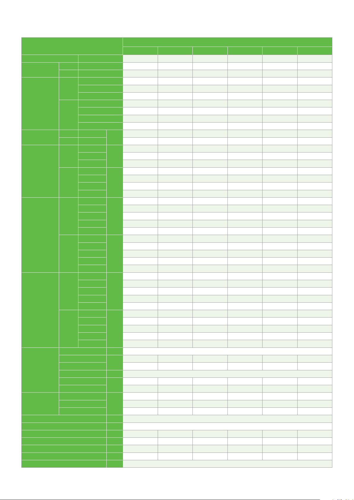
Technical data
Compressor model
Nominal horsepower HP 8 9 10 12 13 15
Displacement
Motor type
Run capacitor
(Sigle phase)
Locked rotor
current (LRA)
Rated load
current (RLA)
Maximum
continuous
current (MCC)
Connection size
Outline
dimension
Sight glass fitting thread in 1-1/4 X 12UNF
Oil type KQ: Mineral oil; KQE: POE
Oil quantity L 2.5 3.25 3.25 3.25 3.3 3.3
Net weight kg 57 59 62 62 62 63
Terminal box IP grade 21 21 21 21 21 21
Crankcase heater power W 90 90 90 90 90 90
Mounting parts installation size (Hole size) mm 190X190 (Ø8.5)
50 Hz m3/hr 22.0 25.7 28.8 33.2 36.4 43.3
60 Hz m3/hr 26.7 31.0 34.8 40.1 43.9 52.3
220-240V-1ph
50 Hz
60 Hz
50 Hz PFJ
50 Hz
60 Hz
KQ
KQE
KQ
KQE
380-420V-3ph TFD TFD TFD TFD TFD TFD
200-220V-3ph TF5 TF5 TF5 TF5 TW5 TW5
208-230V-1ph
460V-3ph TFD TFD TFD TFD TFD TFD
200-230V-3ph TF5 TF5 TF5 TF5 TW5 TW5
380V-3ph TF7 TF7 TF7 TF7 TW7 TW7
PFV
PFJ
TFD 95.0 111.0 118.0 118.0 140.0 174.0
PFV
TF5/TW5 195.0 225.0 239.0 245.0 300.0 340.0
TF7/TW7 123.0 140.0 145.0 145.0 139.0 196.0
TFD 95.0 114.0 125.0 125.0 150.0 179.0
PFJ
PFV
TF5/TW5 32.1 33.6 41.4 47.1 53.6 58.6
TF7/TW7 16.7 18.6 23.6 24.4 28.6 35.7
TFD 16.4 17.3 20.0 22.1 25.0 27.9
PFJ
PFV
TF5/TW5 32.1 33.6 41.4 61.4 65.0
TF7/TW7 18.6 23.6 35.0 42.9
TFD 16.4 17.3 20.0 26.4 28.6
PFJ
PFV
TF5/TW5 45.0 47.0 54.0 66.0 75.0 82.0
TF7/TW7 23.4 26.0 33.1 34.2 40.0 50.0
TFD 23.0 24.2 26.9 31.0 35.0 42.0
PFJ
PFV
TF5/TW5 43.0 44.0 58.0 86.0 91.0
TF7/TW7 29.0 33.0 49.0 60.0
TFD 23.0 24.5 28.0 37.0 40.0
Suction
Discharge 1-1/4 1-1/4 1-1/4 1-1/4 1-1/4 1-1/4
Suction
Discharge 7/8 7/8 7/8 7/8 7/8 7/8
Length
Width 284 284 284 284 285 285
Height 477 546 546 546 552 553
μF / V
AmpsTF5/TW5 203.0 231.0 239.0 273.0
Amps
Amps
Amps
Amps
Amps
mm
ZB58KQ/E ZB66KQ/E ZB76KQ/E ZB88KQ ZB95KQ/E ZB114KQ/E
in
in
1-3/4 1-3/4 1-3/4 1-3/4 1-3/4 1-3/4
1-1/8 1-3/8 1-3/8 1-3/8 1-3/8 1-3/8
264 264 264 264 264 264
ZB Refrigeration scroll 7-15HP
Rotalock connection
Brazing connection
47
Page 48

Technical data
Compressor model
Nominal horsepower HP 20 22 25 30
Displacement
Motor type
Refrigerant R22 R404A R22 R404A R22 R404A R22 R404A
Locked rotor
current (LRA)
Rated load
current
Maximum
continuous
current (MCC)
Connection size
Outline
dimension
Sight glass fitting thread in 1-3/4” x 12 UNF
Oil type Mineral POE Mineral POE Mineral POE Mineral POE
Oil quantity L 4.4 4.7 6.8 6.3
Net weight kg 91.7 140 160 177
Terminal box IP grade IP54 IP56 IP56 IP56
Crankcase heater power W 90 150 150 150
Mounting parts installation size (Hole size) mm 232.0X232.0 (Ø22.6) 266.7 x 266.7 (Ø22.6)
50 Hz m3/hr 45.7 56.6 71.4 87.5
60 Hz m3/hr 55.2 68.3 86.2 105.5
50 Hz
60 Hz
50 Hz
60 Hz
50 Hz
60 Hz
50 Hz
60 Hz
380-420V-3ph TED TED TWD TWD TWD TWD TWD TWD
200V-3ph TEC TEC TWC TWC T WC TWC TWC T WC
460V-3ph TED TED TWD TWD TWD TWD TWD TWD
208-230V-3ph TEC TEC TWC TWC TWC T WC TWC TWC
380V-3ph TE7 TE7 TW7 TW7 TW7 TW7 TW7 TW7
TED/TWD
TEC/TWC 505 610 599
TED/TWD
TEC/TWC 505 610 599
TE7/TW7 343.1 290 353 358
TED/TWD
TEC/TWC 81.4 76.2 100.5 100.5 131.6 155.9
TED/TWD
TEC/TWC 81.4 76.2 100.5 100.5 111.4 131.9
TE7/TW7 36.5 42.1 39.4 55.7 55.7 63.1 74.8
TED/TWD
TE7/TW7 114.0 106.7 140.7 140.7 184.3 218.3
TED/TWD
TEC/TWC 114.0 106.7 140.7 140.7 156.0 184.7
TE7/TW7 51.1 59.0 55.2 78.0 78.0 88.4 104.7
Suction
Discharge 1-3/4 x 12UN
Suction
Discharge 1-1/8 1-3/8
Length
Width 315 376 392 392
Height 662 717 715 715
ZB130KQ ZB130KQE ZB150KQ ZB150KQE ZB190KQ ZB190KQE ZB220KQ ZB220KQE
Amps
Amps
Amps
Amps
Amps
Amps
in
in
mm
287.5 225 272 310
280.7 225 272 310
37.4 33.6 31.4 41.4 41.4 54.3 64.3
40.64 33.6 31.4 41.4 41.4 54.3 64.3
52.3 47.0 44.0 58.0 58.0 76.0 90.0
56.9 47.0 44.0 58.0 58.0 76.0 90.0
315 432 448 448
ZB Large refrigeration scroll 20-30HP
Rotalock connection
2-1/4 x 12UN
Brazing connection
1-5/8
48
Page 49

Dimensional drawings
ZB15-ZB29KQ/KQE
Brazing (BOM 558)
Compressor model A±3 B±3 C±3 D±3 E±3
ZB15KQ/ZB15KQE
363.8 338.3 244.5 202.9 69.6
ZB19KQ/ZB19KQE
ZB21KQ/ZB21KQE 386.4 360.9 264.4 222.8 64.9
ZB26KQ/ZB26KQE 400.2 372.9 277.1 235.5 77.6
ZB29KQ/ZB29KQE 417.8 389.9 294.1 252.5 67.4
49
Page 50

Dimensional drawings
ZB38-ZB48KQ/KQE
Brazing (BOM 558)
Compressor model A±3 B±3 C±3 D
ZB38KQ/ZB38KQE 437.7 409.6 91.3 124.7
ZB45KQ/ZB45KQE 437.7 409.6 77.2 124.7
ZB48KQ/ZB48KQE 443.4 413.7 77.2 128.7
50
Page 51

Dimensional drawings
ZB58KQ/KQE
Brazing (BOM 550)
95.0
242.5 MAX
121.3
190.5
242.5 MAX
132.8
476.3
95.3
121.3
76.6 142.3
444.3
95.3
30°
232.24
190.5
40°
160.0
157.8
164.0
ø22.30~22.42 ID
20.0 Min Copper
Discharge Fitting/Steel
Check Valve
ø28.49~28.67 ID
22.6 Min
0.06 Min Thick Exterior
and 0.038 Min Thick
Interior Copper Plated Steel
Suction Fitting
30°
Sight glass Layout
T-box Removed
19.1
47.9
121.2
Detail FOOT
Scale 1:1
47.5
T-Box layout
Standard
Section
Scale 1:1
93.6
74.3
12.7
A-A
201.5
ø17.45
Pin Circle
444.3
476.3
See Detail FOOT
93.6
201.5
See Detail VALV E
Detail VALV E
Scale 3:4
74.3
67.6
51
Page 52

Dimensional drawings
ZB66-ZB88KQ/KQE
Brazing (BOM 550)
501.2
ø17.45
Pin Circle
533.2
242.5 MAX
121.3
190.5
95.3
190.5
242.5 MAX
95.3
121.3
132.8
533.2
501.2
76.6
30°
40°
142.3
232.24
160.0
157.8
164.0
ø22.30~22.42 ID
20.0 Min Copper
Discharge Fitting/Steel
Check Valve
ø34.84~35.02 ID
22.6 Min
0.06 Min Thick Exterior
and 0.038 Min Thick
Interior Copper Plated Steel
Suction Fitting
Sight glass Layout
T-box Removed
30°
121.2
19.1
47.9
Detail FOOT
Scale 1:1
95.0
47.5
T-Box layout
Standard
Section
Scale 1:1
122.1
A-A
92.3
12.7
242.8
52
See Detail FOOT
92.3
242.8
122.1
See Detail VALV E
Detail VALV E
Scale 3:4
82.1
Page 53

Dimensional drawings
ZB95-ZB114KQ/KQE
Brazing (BOM 550)
242.5 MAX
121.3
190.5
95.3
190.5
242.5 MAX
551.6
95.3
121.3
132.8
519.6
76.6
30°
234.0
40°
142.3
160.0
157.8
164.0
ø22.30-22.42 ID
20.0 Min Copper
Discharge Fitting/Steel
Check Valve
ø34.84-35.02 ID
22.6 Min
0.06 Min Thick Exterior
And 0.038 Min Thick
Interior Copper Plated Steel
Suction Fitting
30°
Sightglass Layout
T-Box Removed
47.9
121.2
Spacer-Mounting Assm
Per Bill of Material
33.3
Detail
FOOT
95.0
47.5
T-Box Layout
Standard
Section
Scale 1:1
92.6
140.5
12.7
A-A
ø17.45
Pin Circle
261.2
519.6
551.6
Scale 1:1
92.6
261.2
140.5
See Detail FOOT
See Detail VALV E
Detail
Scale 3:4
85.5
VALV E
53
Page 54

Dimensional drawings
ZB95-ZB114KQ/KQE (TW7/TW5)
Brazing (BOM 550)
242.5 MAX
121.3
190.5
95.3
121.3
190.5
242.5 MAX
95.3
173.8
164.0
133.0
551.5
519.5
140.5
30°
76.8 207.4
40°
ø22.30~22.42 ID
20.0 Min.
0.038 Min. Thick Exterior
and Interior Copper Plated
Discharge Fitting/
Steel Check Valve
ø34.84~35.02 ID
22.6 Min
0.038 Min. Thick Exterior
and Interior Copper Plated
Steel Suction Fitting
182.0
Terminal Box layout Standard
Scale 3:4
33.3
Detail FOOT
Scale 1:1
85.5
12.6
92.6
54
See Detail FOOT
See Detail VALV E
Detail VALV E
Scale 3:4
Page 55

Dimensional drawings
ZB15-ZB29KQ/KQE
Rotalock (BOM 559)
55
Page 56

Dimensional drawings
ZB38-ZB48KQ/KQE
Rotalock (BOM 559)
253.3-259.3
245.6
122.8
190.5
95.3
95.3
250.4
ø17.45 Pin Circle
Models: TFD, TFE, TFM, TF7
ø13.46 Pin Circle
Models: PFJ, PFV, TFW, TF5, PFZ
245.6
190.5
125.3
44°
132°
A
B
296.7 ±3.0
233.2
C
31°
69.2
242.1
115.2
Ø185.5
122.8
ø25.4 Thread
Rotalock Spud
Discharge
Sight Glass
Per Bill of Material
ø31.75 Thread
Rotalock Spud
Suction
Terminal Box Layout Options
Terminal Box Cover Not Shown
View
A-A
Scale 3:2
A
B
296.70
19.1
233.21
12.7
C
Detail
Scale 2:1
A
56
See Detail
A
Page 57

Dimensional drawings
ZB58KQ/KQE
Rotalock (BOM 551)
242.5 MAX
121.3
190.5
95.3
160.0
95.0
47.5
47.9
ø17.45
Pin Circle
190.5
242.5 MAX
476.3
95.3
157.8
159.3
124.6
121.3
444.3
30°
71.9
232.2
93.6
40°
142.3
Sight glass Layout
T-box Removed
(1.25-12) Thread Rotalock Spud/
Discharge Check Valve
Torque Range 27.1-40.6 Newton-Meter s
(240-360 in-Ibs)
(1.75-12) Thread Rotalock Spud
Suction Fitting
Torque Range 40.6-54.2
Newton-Meters
(360-480 in-Ibs)
201.5
30°
121.2
19.1
Detail FOOT
Scale 1:1
T-Box layout
Standard
A-A
Section
Scale 1:1
93.6
74.3
12.7
476.3
444.3
201.5
74.3
See Detail FOOT
See Detail VALV E
Detail VALV E
Scale 3:4
67.6
57
Page 58

Dimensional drawings
ZB66-ZB88KQ/KQE
Rotalock (BOM 551)
95.0
242.5 MAX
121.3
190.5
95.3
190.5
242.5 MAX
533.2
95.3
124.6
121.3
71.9 142.3
501.2
122.1
30°
232.2
40°
160.0
157.8
159.3
Sight glass Layout
T-box Removed
(1.25-12) Thread Rotalock Spud/
Discharge Check Valve
Torque Range 27.1-40.6 Newton-Meter s
(240-360 in-Ibs)
(1.75-12) Thread Rotalock Spud
Suction Fitting
Torque Range 40.6-54.2
Newton-Meters
(360-480 in-Ibs)
242.8
30°
47.9
121.2
Detail FOOT
19.1
Scale 1:1
47.5
T-Box layout
Standard
Section
Scale 1:1
122.1
92.3
12.7
A-A
242.8
501.2
92.3
ø17.45
Pin Circle
533.2
58
See Detail FOOT
See Detail VALV E
Detail VALV E
Scale 3:4
82.1
Page 59

Dimensional drawings
ZB95-ZB114KQ/KQE
Rotalock (BOM 551)
47.5
T-Box Layout
Section
FOOT
95.0
Standard
A-A
Scale 1:1
140.5
92.6
12.7
261.2
ø17.45
Pin Circle
519.6
551.6
242.5 MAX
121.3
190.5
95.3
190.5
242.5 MAX
551.6
95.3
124.6
121.3
519.6
71.9
234.0
30°
40°
142.3
160.0
157.8
159.3
Sightglass Layout
T-Box Removed
(1.25-12) Thread Rotalock Spud
Discharge Check Valve
Torque Range 100-110 Newton-Meter s
(885-975 in-Ibs)
(1.75-12) Thread Rotalock Spud
Suction Fitting
Torque Range 170-180
Newton-Meters
(1500-1590 in-Ibs)
30°
Spacer-Mounting Assm
Per Bill of Material
47.9
121.2
33.3
Detail
Scale 1:1
See Detail FOOT
92.6
261.2
140.5
See Detail VALVE
85.5
Detail VALV E
Scale 3:4
59
Page 60
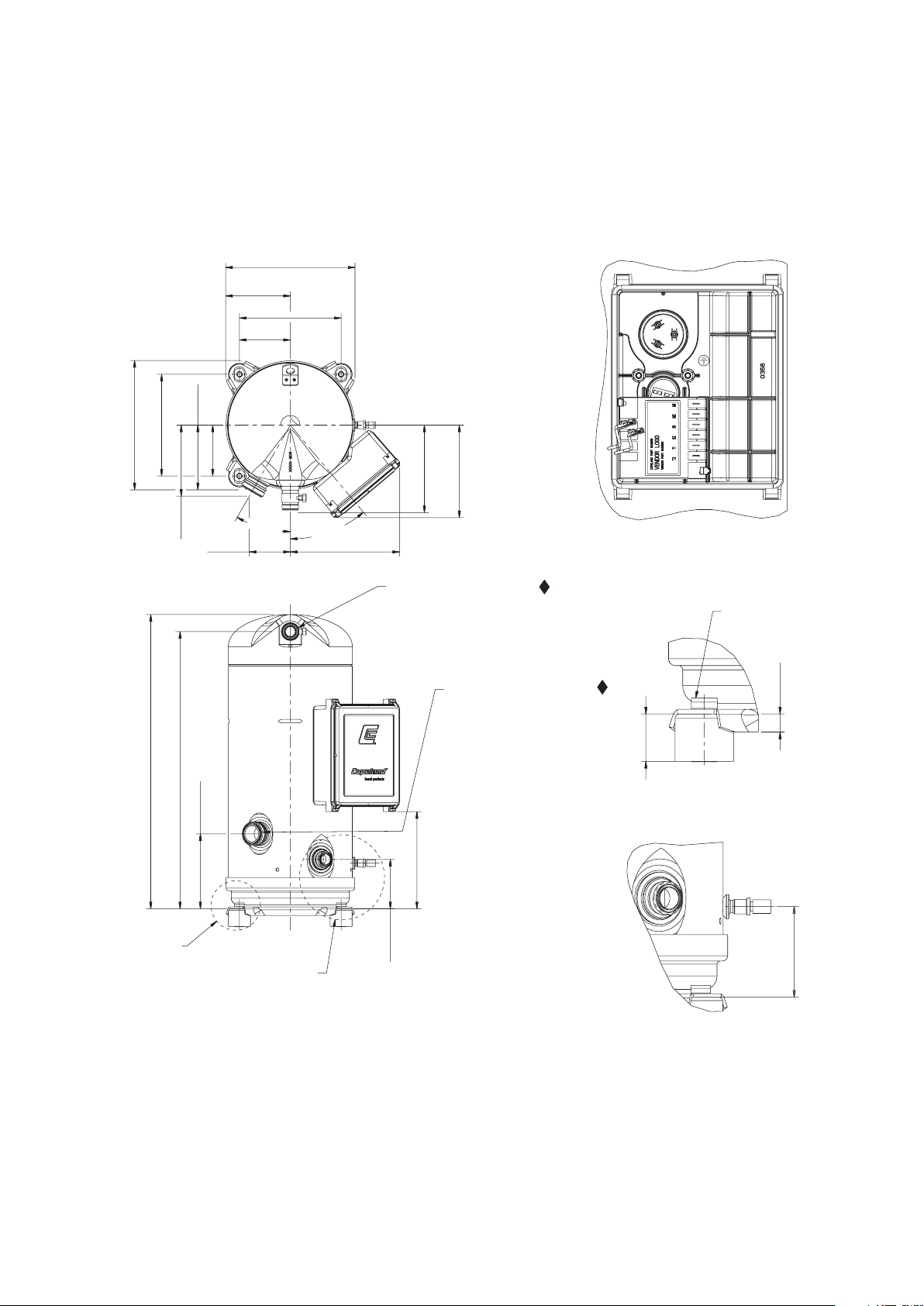
Dimensional drawings
ZB95-ZB114KQ/KQE (TW7/TW5)
Rotalock (BOM 551)
242.5 MAX
121.3
190.5
95.3
121.3
190.5
242.5 MAX
95.3
164.0
173.5
See Detail
551.5
FOOT
133.0
76.8
519.5
140.5
See Detail VALVE
30°
40°
204.7
(1.25-12) Thread Rotalock Spud
Discharge Check Valve
Torque Range 27.1-40.6 Newton-Meter s
(240-360 in-Ibs)
(1.75-12) Thread Rotalock Spud
Suction Fitting
Torque Range 40.6-54.2
Newton-Meters
(360-480 in-Ibs)
182.0
92.6
Terminal Box Layout Standard
Scale 3:4
Spacer-Mounting Assm
Per Bill of Material
12.7
33.3
Detail FOOT
Scale 1:1
85.5
60
Detail
Scale 3:4
VALV E
Page 61

Dimensional drawings
ZB130KQ/KQE
Brazing (BOM 550), Rotalock (BOM 551)
61
Page 62

Dimensional drawings
ZB150KQ/KQE
Brazing (BOM 522), Rotalock (BOM 523)
62
Page 63

Dimensional drawings
ZB190KQ/KQE, ZB220KQ/KQE
Brazing (BOM 522), Rotalock (BOM 523)
63
Page 64

Q1
Electrical wiring diagram
ZB15-ZB114
L1
N
PE
F1
F6
Single phase circuit (ZB15-ZB29)
Electrical schematics
L1/N/PE: Single phase lines (line/neutral/ground)
Q1: Manual switch
K1
N
L1
To Control Circuit
C2
C
R
Q1
L1
L2
L3
N
PE
F1
F6...8
S
M
1
F1/F6: Fuse
K1: Compressor contactor
C2: Run capacitor
M: Compressor motor
R/C/S: Compressor terminal
3 Phase (ZB15-ZB114)
(with Motor Protection Code “F”)
Electrical Schematics
L1/L2/L3/N/PE: 3 Phase Lines (line/neutral/ground)
Q1: Manual Switch
L1
N
F1/F6..8: Fuse
K1: Compressor Contactor
To Control Circuit
K1
L2
L1
L3
M
3
M: Compressor Motor
L1/L2/L3: Compressor Terminal
64
Page 65

Electrical wiring diagram
65
Page 66

Quick application guide
Compression in the scroll is created by
the interaction of an orbiting spiral and
a stationary spiral. Gas enters the outer
openings as one of the spirals orbits.
By the time the gas arrives at the
center port, discharge pressure has
been reached.
Actually, during operation, all six
g
as passages are in various stages
of compression at all times,
resulting in nearly continuous
suction and dischar
g
e.
As the spiral continues to orbit,
the gas is compressed into two
increasingly smaller pockets.
The open passages are sealed off
as gas is drawn into the spiral.
1. Scroll compression process
The scroll is a simple compression concept first patented
in 1905. A scroll is an involute spiral which, when
matched with a mating scroll form as shown above,
generates a series of crescent-shaped gas pockets
between the two members. During compression, one
scroll remains stationary (fixed scroll) while the other
form (orbiting scroll) is allowed to orbit (but not rotate)
around the first form. As this motion occurs, the pockets
between the two forms are slowly pushed to the center
of the two scrolls while simultaneously being reduced
in volume. When the pocket reaches the center of the
scroll form, the gas, which is now at a high pressure, is
discharged out of a port located at the center. During
compression, several pockets are being compressed
simultaneously, resulting in a very smooth process. Both
the suction process (outer portion of the scroll members)
and the discharge process (inner portion) are continuous.
66
Page 67

2. Compressor internal protections
2.1 Internal pressure relief (IPR) Valve
There is an internal pressure relief valve on all ZB15~ZB48
refrigeration scroll compressors which opens at a
differential pressure of 28 bar ± 3 bar between high
and low-pressure sides. A high-pressure cut-out is still
required due to the capabilities of pumping to high
pressures once the discharge is obstructed. The IPR valve
is a safety device, not an HP switch. It is not designed for
repeated operation and there is no guarantee that it will
reset correctly if it does have repeated operation.
ZB58~ZB114, ZB130~ZB220 Copeland Scroll compressors
do not have internal pressure relief (IPR) valves. To avoid
abnormally high operating pressures, a high pressure
control must be used in all applications.
If any type of discharge line shut-off valve is used, the
high pressure control must be installed between the
compressor discharge fitting and the valve. Compressors
with rotalock discharge fittings have a connection on
the rotalock fitting for the high pressure cut-out switch
connection.
The low pressure cut-out setting will depend on the
application type and minimum expected evaporating
temperature. The low pressure cut-out should be selected
to prevent compressor overheating and other system
failure modes.
The minimum, recommended low pressure cut-out
switch settings are:
Refrigerants Low pressure cut-out setting
R22 2.3 bar(g)
R404A 2.0 bar(g)
R134a 0.6 bar(g)
R407F 1.5 bar(g)
2.4 Discharge temperature protection
Events such as loss of charge, condenser fan failure, or
low side charging with inadequate pressure will cause the
discharge gas to quickly rise. Excessively high discharge
gas temperatures would affect the scroll compressor
reliability. To prevent damage to scroll compressors
ZB scroll compressors are built- in with internal scroll
temperature protection.
2.2 High pressure control
A high pressure cut-out control must be used in all
applications. The high pressure control should have
a manual reset feature for the highest level of system
protection.
The maximum, recommended low pressure cut-out
switch settings are:
Refrigerants High pressure cut out setting
R22 25.4 bar(g)
R404A 27.4 bar(g)
R134a 22.3 bar(g)
R407F 23.9 bar(g)
2.3 Low pressure control
A low pressure control is highly recommended for loss
of charge protection and other system fault conditions
that may result in very low evaporating temperatures.
Even though these compressors have internal discharge
temperature protection, loss of system charge will result
in overheating and recycling of the motor overload
protector. Prolonged operation in this manner could
result in oil pump out and eventual bearing failure.
Compressor models ZB15~ZB48 incorporate a thermo
disc which is a temperature-sensitive snap disc device
located at the scroll discharge port or muffler plate. It is
designed to open and route hot discharge gas back to the
motor protector thus removing the compressor from the
line.
ZB58~ZB130 models incorporate ASTP feature (Advanced
Scroll Temperature Protection). ASTP feature will cause
the scrolls to separate and stop pumping but allow the
motor to continue to run. After the compressor runs for
some time without pumping gas, the motor protector
will open. Depending on the heat build up in the
compressor, it may take up to two hours for the motor
protector to reset.
67
Page 68

g
ASTP Feature
ZB150~ZB220 high discharge temperature protection is
provided by a thermistor probe in the discharge plenum
of the scroll. Excessive discharge temperature will cause
the electronic protector module to trip. The discharge gas
thermistor is wired in series with the motor thermistor
chain.
Thermistor
Models ZB95~ZB114, ZB150~ZB220 with motor
protection code “W” and ZB130 with code “E” use a
combination of sensors and an electronic module (refer
to section 2.6) for motor protection. There are a few PTC
(positive temperature coefficient) internal thermistors
connected in series that react with avalanche resistance
in the event of high temperatures. All PTC are used to
sense motor temperature. The thermistor circuit is
connected to the protector module terminals. When any
thermistor reaches a limiting value, the module interrupts
the control circuit and shuts off the compressor. After
the thermistor has cooled sufficiently, the resistance will
decrease, thus allowing the module to reset. However,
the module has a 30-minute time delay before reset after
a thermistor trip.
2.6 External protection module
The ZB130 scroll compressor is equipped with a
CoreSense module. The module is installed in the
compressor electrical box and provides advanced
diagnostics, protection and communications that
enhance compressor performance and reliability.
Internal dischar
2.5 Motor protection
For the models with a motor protection code “F”, an
internal line break motor protector is located in the
center of the Y of the motor windings. This protector
disconnects all three phases in case of an overload or
over-temperature condition. The protector reacts to
a combination of motor current and motor winding
temperature. The internal protector protects against
single phasing. Time must be allowed for the motor
to cool down before the protector will reset. If current
monitoring to the compressor is available, the system
controller can take advantage of the compressor
internal protector operation. The controller can lock out
the compressor if current draw is not coincident with
contactor energizing, implying that the compressor
has shut off on its internal protector. This will prevent
unnecessary compressor cycling on a fault condition until
corrective action can be taken.
e temperature sensor position
The CoreSense Communications Module has the
following key features:
1. Motor temperature protection
2. Missing phase protection
3. Reverse phase protection
4. Low control circuit voltage protection
5. Short cycling detection and alert
6. Communication to system controller through
RS485/Modbus
7. Storage of operational history, runtime information,
and fault counters, etc.
8. Display of status, warning, and alert information
via LEDs
68
Page 69

CoreSense Communications provides compressor and
system protection through its proprietary lockout
feature. Depending on the severity and frequency of
the fault that caused the trip condition, the CoreSense
Communications module can lockout the compressor
contactor to prevent damage to the compressor and
system components. Less severe fault conditions
resulting in an occasional trip will not result in a lockout
condition.
Flashing red and green LEDs communicate Status,
Warning, and Alert codes to the service technician and
the master controller.
Emerson scroll compressors equipped with CoreSense
Communications will have an “E” in the electrical code.
An example, ZB130KQE-TED.
CoreSense communications module specifications
Module part number
T1-T2 Power supply & frequency
Allowable voltage range 85-265 VAC
T2/T1 Low voltage trip 85/170 VAC
T2/T1 Low voltage reset 95/185 VAC
Power consumption 5 VA
M1-M2 Contact rating 2.5A Max
Motor temperature trip resistance > 4.5KΩ ± 25%
Open motor thermistor trip resistance >220KΩ
Shorted motor thermistor trip resistance <40Ω
Motor temperature reset resistance < 2.75KΩ
Reset time after trip 30 minutes
Ambient temperature range -40° to 65°C
571-0064-06
120-240 VAC, 60 Hz
115-230 VAC, 50 Hz
An explanation of the terminal designations follows:
• T2-T1: Module power supply, 120-240 VAC 60 Hz,
115-230 VAC, 50 Hz
• L1-L2-L3: Phase inputs corresponding to compressor
input power L1-L2-L3.
DIP Switch Configuration of ZB130: DIP switch selection
for the Modbus address, baud rate, parity, and other
operating conditions simplify service and start-up
procedures. The following table lists the purpose of each
switch.
DIP Switch purpose
DIP Switch Number On
1 through 5 120-240 VAC, 60 Hz
6 Baud rate = 9600 Baud rate = 19200
7 Even parity No parity
8 Network mode Stand alone
9
PTC
1
10
Thermistor configuration: = PTC only (2 wire connectors)
1
Enable short cycle
protection
Off
Disable short cycle
protection
The module must be reset after changing any of the DIP
switch settings for changes to take effect.
CoreSense Communications modules are shipped from
the factory with the DIP switches set to default settings
for standalone operation. Switch 1 is turned “on” as
part of a quality control check to verify communications
capability of the module before it leaves the compressor
manufacturing plant. All other DIP switch default settings
are in the “off” position.
If DIP switch settings are inadvertently changed, the
compressor will operate, but could have some loss of
protection. Scroll temperature protection and short cycle
protection could be disabled.
Dip-switch Default factory setting
5
2
1
O
ON
4
3
7
6
89
10
F
F
OFF
OFF
OFF
OFF
OFFOFF
OFF
OFFOFF
ROCKER DOWN
• M2-M1: Normally open control circuit contacts;
M2- M1 should be wired in series with the compressor
contactor.
• A (-), GND, B (+): RS485 communications.
• Temperature Plug: the PTC and common connections.
69
Page 70

ZB150-ZB220 scroll compressor equipped with a Kriwan
T1
C
T2
S
T3
R
protection module. The electronic motor protection
system used in all TW* motor code. This system utilizes
the temperature-dependent resistance of the thermistors
(also called PTC-resistance) to read the winding
temperature. A chain of four thermistors connected in
series is embedded in the motor windings so that the
temperature of the thermistors can follow the winding
temperature with little inertia. An electronic module
INT69SCY2 is required to process the resistance values
and trip a control depending on the thermistor resistance
Kriwan protection module specifications
Module part number
Typ e Kriwan diagnose INT69 SC2
Protection
T1- T2 Power supply &
frequency
Power consumption 3 VA
M1-M2 Contact rating 2.5A Max
Trip resistance >4.5KΩ
Reset resistance <2.75KΩ
Reset time after trip 30 minutes
Ambient temperature range -30°C to +70°C
Motor temperature reset
resistance
Reset time after trip 30 minutes
Ambient temperature range -40° to 65°C
071-0684-00
Motor & scroll temperature
protection
120-240 VAC, 60 Hz
115-230 VAC, 50 Hz
< 2.75KΩ
3. Compressor information
3.1 Fusite (Terminal)
Fusite (Terminal) pin orientation for single-phase and
three phase refrigeration scroll compressors are shown in
below and inside the terminal box.
Motor Terminal (Fusite) Connections for
Single Phase and Three Phase Scrolls
3.2 Three-phase rotation direction
Scroll compressors are directional dependent: i.e., they
will compress in one rotational direction only. On
single-phase compressors, this is not an issue since they
will only start and run in the proper direction. Three-
phase scrolls, however, will rotate in either direction
depending on the power of the phasing. So there is a
50/50 chance of connected power being “backwards.”
Contractors should be warned of this. Appropriate
instructions or notices should be provided by the Original
Equipment Manufacturer.
Verification of proper rotation can be made by observing
that the suction pressure drops and the discharge
pressure rises when the compressor is energized.
Additionally, if operated in reverse the compressor is
noisier and its current draw is substantially reduced
compared to tabulated values.
Although operation of scroll in reverse direction for brief
periods of time is not harmful, continued operation could
result in failure.
An explanation of the terminal designations follows:
• T2-T1: Module power supply, 120-240 VAC 60 Hz,
115-230 VAC, 50 HZ
• S2-S1: Connect to motor and scroll PTC sensors
• M2-M1: Normally open control circuit contacts;
M2- M1 should be wired in series with the compressor
contactor.
70
All three-phase compressors are wired identically
internally. Once the correct phasing is determined for
a specific system or installation, connecting properly
phased power leads to the same fusite terminals will
maintain the proper rotation.
Page 71

3.3 Brief power interruptions
Brief power interruptions (less than 0.5 second) may
result in powered reverse rotation of single-phase
refrigeration scroll compressors. High-pressure discharge
gas expands backward through the scrolls at power
interruption causing the scroll to orbit in the reverse
direction. If power is reapplied while this reversal is
occurring, the compressor may continue to run noisily
in the reverse direction for several minutes until the
compressor internal protector trips. This has no negative
effect on durability. When the protector resets, the
compressor will start and run normally.
Emerson strongly encourages the use of a timer which
can sense brief power interruptions and lock the
compressor out of operation for two minutes.
No time delay is required on three phase models to
prevent reverse rotation due to power interruptions.
3.4 Oil types
In HCFC R22 applications, mineral oil is used in the
compressor. Polyol ester lubricants must be used with
HFC refrigerants (R404A, R507, R134a, R407F, R448A
and R449A). Compressors using polyol ester oil are
identified with an “E” in the model number. A separate
form may be requested (Form 93-11) which lists Emerson
approved lubricants that may be used to recharge these
compressors or if the addition of oil is required. See
compressor nameplate for original oil charge. A complete
recharge should be four ounces (118ml) less than the
original oil charge. If the oil level is above the sight glass,
it may lead to oil circulation rates higher than 1.5% which
may lead to decreased capacity as the oil coats the
evaporator coils.
3.5 Deep vacuum operation
WARNING: Do not run a refrigeration scroll compressor
in a vacuum. Failure to heed this advice can result in
permanent damage to the compressor.
A low-pressure control is required for protection against
vacuum operation. See the section 2.3 on pressure
controls for the proper set points.
Scrolls compressors (as with any refrigeration
compressor) should never be used to evacuate
refrigeration or air conditioning systems.
The scroll compressor can be used to pump-down
refrigerant in a unit as long as the pressures remain within
the operating envelope. Low suction pressures will result
in overheating of the scrolls and permanent damage
to the compressor drive bearing or cause the scroll
temperature protection to activate.
3.6 Shell temperature
Certain types of system failures, such as condenser or
evaporator fan blockage or loss of charge, may cause the
top shell and discharge line to briefly but repeatedly reach
temperatures above 350°F (177°C) as the compressor
cycles on its internal protection devices. Care must be
taken to ensure that wiring or other materials, which
could be damaged by these temperatures, do not come
in contact with these potentially hot areas.
3.7 Suction and discharge fittings
Scroll compressors are available with stub tube or
rotalock connections. The stub tube version has copper
plated steel suction and discharge fittings. These fittings
are far more rugged than copper fittings used on other
compressors. Due to the different thermal properties
of steel and copper, brazing procedures may have to
be changed from those commonly used. Assembly and
brazing procedures are explained in the later part of
application guide.
3.8 Starting characteristics of single-phase compressors
Single-phase scroll compressors are designed with PSC
type motors and therefore will start without the need of
start assist devices in most applications. However, if low
voltage conditions exist at start up, protector trips can
result. Therefore, start assist devices (start capacitors and
relays) are available to maximize starting characteristics
under abnormal conditions.
71
Page 72

3.9 Special handling consideration for ZB58-ZB114
ZB58- ZB114 model compressors have the suction fitting
located low on the shell. Due to this, it’s recommended
to leave the suction connection plug in place until the
compressor is set into the unit. The discharge connection
plug should be removed first before pulling the suction
connection plug to allow the dry air pressure inside the
compressor to escape. Pulling the plugs in this sequence
prevents oil mist from coating the suction tube making
the brazing difficult. The copper coated steel suction tube
should be cleaned before brazing. No object (example a
swaging tool) should be inserted deeper than 50mm into
the suction tube or it might damage the suction screen
and motor.
3.10 Electrical information
Locked rotor current (LRA)
LRA is the higher average current as measured on a
mechanically blocked compressor tested under nominal
voltage. LRA is printed on the nameplate.
The LRA value can be used as a rough estimation for the
starting current. However in most cases, the real starting
current will be lower. Many countries have defined limits
for the starting current in domestic use. A soft starter can
be applied to reduce starting current.
Maximum continuous current (MCC)
The MCC is the current at which the internal motor
protection trips under maximum load and low voltage
conditions.
This MCC valve is the maximum at which the compressor
can be operated in transient conditions and out of the
application envelope. Above this valve the overload will
switch off to protect the motor.
Maximum operating current (MOC)
The maximum operating current is the current when
the compressor operates at maximum load conditions
and 10% below nominal voltage. This valve, which is the
maximum rated load current for the compressor. MOC is
printed on the nameplate.
The MOC can be used to select cables and contactors. In
normal operation, the compressor current consumption
is always less than the MOC valve.
4. System protection guidelines
4.1 Accumulator requirement
Due to the scrolls’ inherent ability to handle liquid
refrigerant in flooded start and defrost cycle operation
conditions, accumulators may not be required. An
accumulator is required on single compressor systems
when the charge limitations exceed those values listed in
the table. On systems with defrost schemes or transient
operations that allow prolonged uncontrolled liquid
return to the compressor, an accumulator is required.
Excessive liquid flood back or repeated flooded starts
will dilute the oil in the compressor causing inadequate
lubrication and bearing wear. Proper system design will
minimize liquid flood back, thereby ensuring maximum
compressor life.
Models Refrigerant charge limits
ZB15-ZB29 3.6 Kg
ZB38-ZB48 4.5 Kg
ZB58-ZB114 7.5 Kg
ZB150-ZB220 11.3 Kg
4.2 Crankcase heaters requirement
A crankcase heater is used to prevent refrigerant
migrating into the shell during standstill periods.
Crankcase heaters are required on three phase
compressors when the system charge exceeds the
charge limits. This requirement is independent of system
type and configuration. The crankcase heater must
be turned on a minimum of 12 hours prior to starting
the compressor and must remain energized during
compressor off cycles.
The heater should be installed as close as possible to the
bottom of the compressor but should avoid weld points
that could cause poor thermal contact. The clamp should
straddle the vertical seam weld of the compressor shell
to avoid a hot spot on the heater element. It is important
that the clamp screw is torqued to the range of 2.3-
2.8 N-m (20-25 in-lb) to ensure adequate contact and
to prevent heater burnout. Never apply power to the
heater in free air or before the heater is installed on the
compressor to prevent overheating and burnout.
72
Page 73

Crankcase Heater Location – ensure that clamp is over the
vertical weld sea
4.3 Pump-down cycle
A pump-down cycle for control of refrigerant migration
may be used instead of, or in conjunction with, a
crankcase heater when the compressor is located so
that cold air blowing over the compressor makes the
crankcase heater ineffective. A separate external check
valve must be added to the discharge line if pump-
down is used. The built-in scroll discharge check valve
is designed to stop extended reverse rotation and
prevent high pressure gas from leaking rapidly into the
low side after shut off. High side leak-back through
the check valve may exceed amounts typically found
in reciprocating compressors with reed valves. This
can cause the compressor to recycle more frequently.
Repeated short-cycling of this nature can result in
low compressor oil and consequent damage to the
compressor. The recommended external check valve
will prevent the frequent recycling due to leak-back. The
low pressure control cut-in and cut-out settings have to
be reviewed since a relatively large volume of gas will re-
expand from the high side of the compressor into the low
side on shut down. Emerson recommends that the cut
out setting of the pump-down pressure control be set no
more than a few degrees of equivalent saturated pressure
below the lowest expected normal operating pressure. It
is not necessary to pump-down into nearly a vacuum to
remove all liquid refrigerant for the low side. To achieve
a fairly wide control differential the cut in setting should
be set a few degrees of equivalent saturated pressure
below the lowest expected temperature of the medium
that is cooled. Copeland Scroll compressors trap a
considerable volume of high pressure gas between the
muffler plate and the top cap. When the compressor
shuts down the trapped gas will expand back into the
suction side of the system. This frequently causes a pulse
of pressure to propagate down the suction line and can
cause the low pressure switch to reset. The compressor
must not be allowed to short cycle which may result in
oil pump out. The electrical circuitry should be arranged
so that compressor restart is triggered by demand from
the thermostat rather than a reset low pressure switch.
Setting a wider differential between the cutout and cut
in pressures of a low pressure switch may solve the short
cycling problem but may also result in unacceptable
temperature swings in the cooled space. If short cycling
cannot be avoided, using a 3 minute time delay will limit
the cycling of the compressor to an acceptable level.
4.4 Filter screens in system
The use of screens finer than 30 x 30 mesh (0.6 mm
openings) anywhere in the system is not recommended.
Field experience has shown that finer mesh screens used
to protect thermal expansion valves, capillary tubes, or
accumulators can become temporarily or permanently
plugged with normal system debris and block the flow of
either oil or refrigerant to the compressor. Such blockage
can result in compressor failure.
5. Testing guidelines
5.1 Compressor hi-pot testing
Refrigeration scroll compressors are configured with
the motor in the bottom of the shell. Unlike most other
hermetic compressors, the motor of a scroll compressor
can be immersed in refrigerant when liquid is present
in the shell. Hi- Pot tests with liquid refrigerant in the
shell can show higher levels of current leakage due to
the higher electrical conductivity of liquid refrigerant vs.
refrigerant vapor and oil. This phenomenon can occur
with any compressor when the motor is immersed in
refrigerant and does not present any safety issue. To
lower the current leakage reading, operate the system
for a brief period of time redistributing the refrigerant to
a more normal configuration and test again. Under no
circumstances should the Hipot test be performed while
the compressor is in vacuum.
5.2 Scroll compressor functional check
A functional compressor test with the suction service
valve closed to check how low the compressor will pull
suction pressure is not a good indication of how well
a compressor is performing. Such a test will almost
certainly damage a scroll compressor. The following
diagnostic procedure should be used to evaluate whether
a Copeland Scroll compressor is working properly.
73
Page 74

1. Proper voltage to the unit should be verified.
2. The normal checks of motor winding continuity
and short to ground should be made to determine
if the inherent overload motor protector has
opened or if an internal motor short or ground fault
has developed. If the protector has opened, the
compressor must be allowed to cool sufficiently to
allow it to reset.
3. Proper indoor and outdoor blower/fan operation
should be verified.
4. With service gauges connected to suction and
discharge pressure fittings, turn on the compressor. If
suction pressure falls below normal levels, the system
is either low on charge or there is a flow blockage in
the system.
5. In single phase compressors, if suction pressure
does not drop and discharge pressure does not rise
to normal levels the compressor is faulty. But in
three phase compressors, reverse any two of the
compressor power leads and reapply power to make
sure compressor was not wired to run in reverse
direction.
6. Before replacing, be certain that the compressor
is actually defective. As a minimum, recheck a
compressor returned from the field in the shop or
depot for Hi-pot, winding resistance, and ability to
start. Experience shows that more than one third
of compressors are determined to have nothing
found wrong. They were mis-diagnosed in the field
as being defective. Replacing working compressors
unnecessarily costs everyone.
7. NEVER test a scroll compressor by closing the
suction valve or the liquid feed to the evaporator and
pumping the compressor into a vacuum.
6. Field & installation guidelines
6.1 Assembly line and field brazing
ZB Scroll compressors are available with stub tube
and rotalock connections. The stub tube version has
copper plated steel suction and discharge fittings. Due
to the different thermal properties of steel and copper,
brazing procedures may have to be changed from those
commonly used The guidelines below gives a description
for assembly line and field brazing procedures.
321
New installations
The copper-coated steel suction and discharge tubes on
scroll compressors can be brazed in approximately the
same manner as any copper tube.
• Recommended brazing materials: Any silfos material is
recommended, preferably with a minimum of 5% silver.
However, 0% silver is acceptable.
• Be sure compressor tube fittings I.D. and connecting
tube O.D. are clean prior to assembly. If oil film is
present wipe with denatured alcohol, DichloroTrifluoroethane or other suitable solvent.
• Using a double-tipped torch apply heat in Area 1. As
tube approaches brazing temperature, move torch
flame to Area 2.
• Heat Area 2 until braze temperature is attained,
moving torch up and down and rotating around tube
as necessary to heat tube evenly. Add braze material to
the joint while moving torch around joint to flow braze
material around circumference.
• After braze material flows around joint, move torch
to heat Area 3. This will draw the braze material down
into the joint. The time spent heating Area 3 should be
minimal.
• As with any brazed joint, overheating may be
detrimental to the final result.
6.2 Field service
Unbrazing system components
CAUTION! If the refrigerant charge is removed from a
scroll unit by bleeding the high side only, it is sometimes
possible for the scrolls to seal preventing pressure
equalization through the compressor. This may leave
the low side shell and suction line tubing pressurized.
If a brazing torch is then applied to the low side, the
pressurized refrigerant oil mixture could ignite as it
escapes and contacts the brazing flame. It is important to
check both the high and low sides with manifold gauges
before unbrazing. In the case of an assembly line repair,
remove the refrigerant from both the high and low sides.
74
Page 75

Instructions should be provided in appropriate product
literatures and assembly areas.
• To disconnect: Reclaim refrigerant from both the
high and low side of the system. Cut tubing near
compressor.
• To reconnect. Recommended brazing material is Silfos
with minimum 5% silver or silver braze material with
flux. Insert tubing stubs into fitting and connect to
the system with tubing connectors. Follow Installation
brazing instructions.
Brazing procedure
Section 6.1 discusses the proper procedures for brazing
the suction and discharge lines to a Copeland Scroll
compressor. It is important to flow nitrogen through
the system while brazing all joints during the system
assembly process. Nitrogen displaces the air and prevents
the formation of copper oxides in the system.
If allowed to form, the copper oxide flakes can later be
swept through the system and block screens such as
those protecting capillary tubes, thermal expansion
valves, and accumulator oil return holes. The blockage
- whether it is of oil or refrigerant - is capable of doing
damage resulting in compressor failure.
6.3 Compressor replacement after motor burn
In the case of a motor burn, the majority of contaminated
oil will be removed with the compressor. The rest of
the oil is cleaned through use of suction and liquid line
filter dryers. A 100% activated alumina suction filter
drier is recommended but must be removed after
72 hours. Separate bulletins are available on request
for clean-up procedures and for liquid line filter drier
recommendations. AE Bulletin 24-1105 for clean-up
procedures and AE Bulletin 11-1297 for liquid line filter
drier recommendations.
6.4 System charging procedure
Systems should be charged with liquid on the high side to
the extent possible. The majority of the charge should be
pumped into the high side of the system to prevent hi pot
failures, and bearing washout during first time start. If
additional charge is needed, it should be added as liquid,
in a controlled manner, to the low side of the system with
the compressor operating. Pre-charging on the high side
and adding liquid on the low side of the system are both
meant to protect the compressor from operating with
abnormally low suction pressures during charging.
Do not start the compressor while the system is in a deep
vacuum. Internal arcing may occur when a compressor
is started in a vacuum Do not operate compressor
without enough system charge to maintain at least
7 psig (0.5Kg/cm²) suction pressure. Do not operate
with a restricted suction. Do not operate with the low
pressure cut-out jumpered. Allowing pressure to drop
below 2°F(-16°C) for more than a few seconds may
overheat scrolls and cause early drive bearing damage
or cause the scroll temperature protection to activate.
Do not use compressor to test opening set point of high
pressure cutout. Bearings are susceptible to high load
damage before they have had several hours of normal
running for proper break in. Never install a system in the
field and leave it unattended with no charge, or with the
service valves closed without securely locking out the
system. This will prevent unauthorized personnel from
accidentally operating the system and potentially ruining
the compressor by operating with no refrigerant flow.
It is highly recommended that the suction accumulator
be replaced if the system contains one. This is because
the accumulator oil return orifice or screen may be
plugged with debris or may become plugged shortly after
a compressor failure. This will result in starvation of oil to
the replacement compressor and a second failure.
75
Page 76

Available models list
Motor
PFJ
220-240V-1ph-50 Hz;
265v-1ph-60 Hz
PFV
200v-1ph-50 Hz;
208-230V-1ph-60 Hz
TFD/TWD
380-420V-3ph-50 Hz;
460V-3ph-60 Hz
ZB Refrigeration scroll models
Rotalock Stub tube Manufacturing plant Status
ZB15KQ/E-PFJ-559 ZB15KQ/E-PFJ-558 Thailand/Suzhou Active
ZB19KQ/E-PFJ-559 ZB19KQ/E-PFJ-558 Thailand/Suzhou Active
ZB21KQ/E-PFJ-559 ZB21KQ/E-PFJ-558 Thailand/Suzhou Active
ZB26KQ/E-PFJ-559 ZB26KQ/E-PFJ-558 Thailand/Suzhou Active
ZB29KQ/E-PFJ-559 ZB29KQ/E-PFJ-558 Thailand/Suzhou Active
ZB15KQ/E-PFV-559 ZB15KQ/E-PFV-558 Thailand/Suzhou Active
ZB19KQ/E-PFV-559 ZB19KQ/E-PFV-558 Thailand/Suzhou Active
ZB21KQ/E-PFV-559 ZB21KQ/E-PFV-558 Thailand/Suzhou Active
ZB26KQ/E-PFV-559 ZB26KQ/E-PFV-558 Thailand/Suzhou Active
ZB29KQ/E-PFV-559 ZB29KQ/E-PFV-558 Thailand/Suzhou Active
ZB38KQ/E-PFV-559 ZB38KQ/E-PFV-558 Thailand Active
ZB15KQ/E-TFD-559 ZB15KQ/E-TFD-558 Thailand/Suzhou Active
ZB19KQ/E-TFD-559 ZB19KQ/E-TFD-558 Thailand/Suzhou Active
ZB21KQ/E-TFD-559 ZB21KQ/E-TFD-558 Thailand/Suzhou Active
ZB26KQ/E-TFD-559 ZB26KQ/E-TFD-558 Thailand/Suzhou Active
ZB29KQ/E-TFD-559 ZB29KQ/E-TFD-558 Thailand/Suzhou Active
ZB38KQ/E-TFD-559 ZB38KQ/E-TFD-558 Thailand/Suzhou Active
ZB45KQ/E-TFD-559 ZB45KQ/E-TFD-558 Thailand/Suzhou Active
ZB48KQ/E-TFD-559 ZB48KQ/E-TFD-558 Thailand/Suzhou Active
ZB58KQ/E-TFD-551 ZB58KQ/E-TFD-550 Thailand/Suzhou Active
ZB66KQ/E-TFD-551 ZB66KQ/E-TFD-550 Thailand/Suzhou Active
ZB76KQ/E-TFD-551 ZB76KQ/E-TFD-550 Thailand/Suzhou Active
ZB88KQ-TFD-551 ZB88KQ-TFD-550 Thailand/Suzhou Active
ZB95KQ/E-TFD-551 ZB95KQ/E-TFD-550 Thailand/Suzhou Active
ZB114KQ/E-TFD-551 ZB114KQ/E-TFD-550 Thailand/Suzhou Active
ZB114KQ/E-TWD-551 ZB114KQ/E-TWD-550 Thailand Active
ZB130KQ/E-TED-551 ZB130KQ/E-TED-550 Suzhou Active
ZB150KQ/E-TWD-523 ZB150KQ/E-TWD-522 Suzhou Active
ZB190KQ/E-TWD-523 ZB190KQ/E-TWD-522 Suzhou Active
ZB220KQ/E-TWD-523 ZB220KQ/E-TWD-522 Suzhou Active
76
Page 77

Motor
TF7/TW7
380V-3ph-60 Hz
TF5/TW5
200-220V-3ph-50 Hz;
200-230V-3ph-60 Hz
TWC
200V-3ph-50 Hz;
208-230V-3ph-60 Hz
KQ: Mineral oil
KQE: POE
ZB Refrigeration scroll models
Rotalock Stub tube Manufacturing plant Status
ZB15KQ/E-TF7-559 ZB15KQ/E-TF7-558 Thailand Active
ZB19KQ/E-TF7-559 ZB19KQ/E-TF7-558 Thailand Active
ZB21KQ/E-TF7-559 ZB21KQ/E-TF7-558 Thailand Active
ZB26KQ/E-TF7-559 ZB26KQ/E-TF7-558 Thailand Active
ZB29KQ/E-TF7-559 ZB29KQ/E-TF7-558 Thailand Active
ZB38KQ/E-TF7-559 ZB38KQ/E-TF7-558 Thailand Active
ZB45KQ/E-TF7-559 ZB45KQ/E-TF7-558 Thailand Active
ZB48KQ/E-TF7-559 ZB48KQ/E-TF7-558 Thailand Active
ZB58KQ/E-TF7-551 ZB58KQ/E-TF7-550 Thailand Active
ZB66KQ/E-TF7-551 ZB66KQ/E-TF7-550 Thailand Active
ZB76KQ/E-TF7-551 ZB76KQ/E-TF7-550 Thailand Active
ZB88KQ-TF7-551 ZB88KQ-TF7-550 Thailand Active
ZB95KQ/E-TF7-551 ZB95KQ/E-TF7-550 Thailand Active
ZB95KQ/E-TW7-551 ZB95KQ/E-TW7-550 Thailand Active
ZB114KQ/E-TW7-551 ZB114KQ/E-TW7-550 Thailand Active
ZB130KQ/E-TE7-551 ZB130KQ/E-TE7-550 Suzhou Active
ZB150KQ/E-TW7-523 ZB150KQ/E-TW7-522 Suzhou Active
ZB190KQ/E-TW7-523 ZB190KQ/E-TW7-522 Suzhou Active
ZB220KQ/E-TW7-523 ZB220KQ/E-TW7-522 Suzhou Active
ZB15KQ/E-TF5-559 ZB15KQ/E-TF5-558 Thailand Active
ZB19KQ/E-TF5-559 ZB19KQ/E-TF5-558 Thailand/Suzhou Active
ZB21KQ/E-TF5-559 ZB21KQ/E-TF5-558 Thailand/Suzhou Active
ZB26KQ/E-TF5-559 ZB26KQ/E-TF5-558 Thailand/Suzhou Active
ZB29KQ/E-TF5-559 ZB29KQ/E-TF5-558 Thailand/Suzhou Active
ZB38KQ/E-TF5-559 ZB38KQ/E-TF5-558 Thailand/Suzhou Active
ZB45KQ/E-TF5-559 ZB45KQ/E-TF5-558 Thailand Active
ZB48KQ/E-TF5-559 ZB48KQ/E-TF5-558 Thailand Active
ZB58KQ/E-TF5-551 ZB58KQ/E-TF5-550 Thailand Active
ZB66KQ/E-TF5-551 ZB66KQ/E-TF5-550 Thailand Active
ZB76KQ/E-TF5-551 ZB76KQ/E-TF5-550 Thailand Active
ZB95KQ/E-TW5-551 ZB95KQ/E-TW5-550 Thailand Active
ZB114KQ/E-TW5-551 ZB114KQ/E-TW5-550 Thailand Active
ZB130KQ/E-TEC-551 ZB130KQ/E-TEC-550 Suzhou On hold
ZB150KQ/E-TWC-523 ZB150KQ/E-TWC-522 Suzhou On hold
ZB190KQ/E-TWC-523 ZB190KQ/E-TWC-522 Suzhou On hold
ZB220KQ/E-TWC-523 ZB220KQ/E-TWC-522 Suzhou On hold
77
Page 78

Notes
78
Page 79

Notes
79
Page 80

Contact lists
Asia Pacific Headquarters
Suite No. 2503-10A, 25/F,
Exchange Tower, 33 Wang Chiu Road,
Kowloon Bay, Kowloon, Hong Kong
Tel: (852) 2866 3108
Fax: (852) 2520 6227
Australia
356 Chisholm Road
Auburn NSW 2144, Australia
Tel: (612) 9795 2800
Fax: (612) 9738 1699
China - Beijing
Room 1203-1205,
North Wing Junefield Plaza Central Tower,
No. 10 Xuan Wu Men Wai Street,
XiCheng District, Beijing, PRC
Tel: (8610) 5095 2188
China - Guangzhou
Guangzhou Office
Unit 2202B, 22/F, Leatop Plaza,
32 Zhujiang East Road, Tianhe Dist.,
Guangzhou 510623, PRC
Tel: (8620) 8595 5188
China - Shanghai
Shanghai Sales Office
7F, Emerson Building, 1582 Gumei
Rd, Shanghai, PRC
Tel: (8621) 3338 7333
India - Mumbai
Delphi B-Wing, 601-602, 6th Floor
Central Avenue,
Hiranandani Business Park,
Powai, Mumbai 400076, India
Tel: (9122) 6786 0793
Fax: (9122) 6662 0500
India - Pune
Plot No. 23, Rajiv Gandhi Infotech Park,
Phase - II, Hinjewadi,
Pune 411 057, Maharashtra, India
Tel: (9120) 4200 2000
Fax: (9120) 4200 2099
Indonesia
BSD Taman Tekno 8
Jl. Tekno Widya Blok H10 No 2 & 3
Tangerang Selatan 15314
Indonesia
Tel: (6221) 2966 6242
Fax: (6221) 2966 6245
Japan
Shin-yokohama Tosho Building
No. 3-9-5 Shin-Yokohama, Kohoku-ku
Yokohama 222-0033 Japan
Tel: (8145) 475 6371
Fax: (8145) 475 3565
Malaysia
Level M2, Blk A, Menara PKNS-PJ
Jalan Yong Shook Lin
46050 Petaling Jaya, Selangor, Malaysia
Tel: (603) 7949 9222
Fax: (603) 7949 9333
Middle East & Africa
PO Box 26382
Jebel Ali Free Zone - South
Dubai, UAE
Tel: (9714) 811 8100
Fax: (9714) 886 5465
Philippines
10/F SM Cyber West Avenue, EDSA cor.
West Avenue, Barangay Bungad,
Diliman, Quezon City 1105 Philippines
Tel: (632) 689 7200
Saudi Arabia
PO Box 34332 - 3620 Building 7874
Unit 1, 67th street 2nd Industrial City
Dammam, Saudi Arabia
Toll Free: 800 844 3426
Tel: +966 3 8147560
Fax: +966 3 8147570
South Korea
3F, The Pinnacle Gangnam
343, Hakdong-ro, Gangnam-gu,
Seoul 06060, Republic of Korea
Tel: (822) 3483 1500
Fax: (822) 592 7883
Taiwan
3F No. 122 Lane 235,
Pao Chiau Rd., XinDianv Dist.,
New Taipei City 23145, Taiwan (R.O.C.)
Tel: (8862) 8912 1360
Fax: (8862) 8912 1890
Thailand
34th Floor, Interlink Tower,
1858/133, Bangna Trad,
Bangkok 10260, Thailand
Tel: (662) 716 4700
Fax: (662) 751 4241
United Arab Emirates
Jebel Ali Free Zone
PO Box 26382
Dubai UAE
Toll Free: 800 441 3428
Tel: +971 4 811 8100
Fax: +971 4 886 5465
Vietnam
Level 6, Melinh Point Tower,
2 Ngo Due Ke,
District 1, Ho Chi Minh City
Vietnam
Tel: (84) 908 009 189
Climate.Emerson.Com/Asia/Refrigeration
Asia 01 00 Issued 04/2020 Emerson is a trademark of Emerson Electric Co. or one of its affiliated companies.
©2020 Emerson Electric Co. All rights reserved.
80
Scan to visit:
Emerson Asia
@EmersonComResAP
 Loading...