

Page 1
en
2
1
Maintenance Guide
Reference: 5060 en -
2015.09 / b
COMPABLOC 3000
Page 2
12
COMPABLOC 3000 Maintenance Guide
5060 en - 2015.09 / b
CONTENTS
GENERAL WARNING
1 - HOW TO ORDER ............................................................................................................................................... 13
2 - INSTRUCTIONS FOR DISMANTLING AND REBUILDING ............................................................................... 13
2.1 - Dismantling ............................................................................................................................................... 13
2.2 - Rebuilding .................................................................................................................................................. 13
3 - EXPLODED VIEWS - PARTS LIST .................................................................................................................... 14
3.1 - Compabloc multistage .............................................................................................................................. 14
3.1.1 - Compabloc multistage exploded views: Cb 3032 to Cb 3833 ............................................................................. 14
3.1.2 - Compabloc multistage parts list: Cb 30xx to Cb 38xx .......................................................................................... 15
3.2 - Compabloc 1 stage ................................................................................................................................... 16
3.2.1 - Compabloc 1 stage exploded views: Cb 3031 to Cb 3531 .................................................................................. 16
3.2.2 - Compabloc 1 stage parts list: Cb 3031 to Cb 3531 .............................................................................................. 16
3.3 - Input shaft AP and input shaft with AD backstop ........................................................................................ 17
3.3.1 - AP and AP-AD exploded views ........................................................................................................................... 17
3.3.2 - AP and AP-AD parts list ...................................................................................................................................... 17
3.4 - MU universal mounting and MU-AD universal mounting with AD backstop ............................................... 18
3.4.1 - MU and MU-AD exploded views ......................................................................................................................... 18
3.4.2 - MU and MU-AD parts list .................................................................................................................................... 19
3.5 - Motor ......................................................................................................................................................... 20
3.5.1 - Motor exploded views ......................................................................................................................................... 20
3.5.2 - Motor parts list .................................................................................................................................................... 20
This document is an addition to the general manual ref. 2557 (recommendations), ref. 3711, ref. 3804 (Atex specic
recommendations), and manual ref. 3520 (Compabloc 3000 installation).
NOTE
LEROY-SOMER gives no contractual guarantee whatsoever concerning the information published in this document and cannot be
held responsible for any errors it may contain, nor for any damage resulting from ist use.
CAUTION
The specications, instructions and descriptions are for standard operation. They do not take account of structural variants or
special adaptations. Failure to comply with these recommendations may lead to premature deterioration of the gearbox and
voiding of the manufacturer’s guarantee.
Despite all the care taken in the manufacture and checking of this equipment, LEROY-SOMER cannot guarantee that lubricant will
not escape during the product’s lifetime. If slight leaks could have serious consequences for the safety of people and property, the
installer and user should take all necessary precautions to avoid such consequences.
Page 3
13
HOW TO ORDER
COMPABLOC 3000 Maintenance Guide
5060 en - 2015.09 / b
en
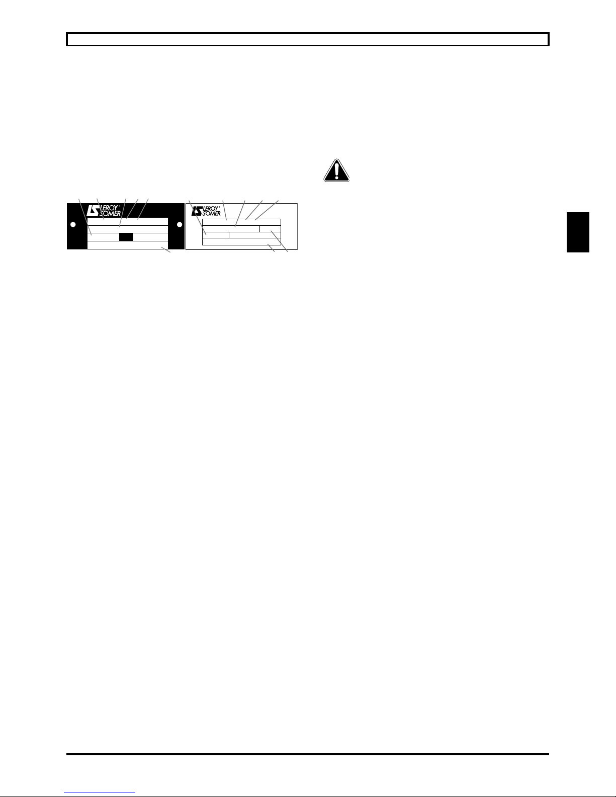
1 - HOW TO ORDER
Necessary information
a) from the gearbox nameplate:
1- gearbox model and size;
2- operating position;
3- xing type (S with foot, BS, BDn or BT…);
4- exact reduction;
- possible options;
5- serial number;
6- lubricant;
7- backlash: Standard (DYNABLOC).
b) from the appropriate part list:
- part description and item number.
c) Where a motor is tted to the gearbox, from the motor
nameplate:
(for the motor: see the corresponding manual)
- motor type;
- No. of poles (or speed in min-1);
- power in kW (or N.m).
Caution: the motor requires a special shaft and ange for
integral mounting (MI) with the gearbox.
2 - INSTRUCTIONS FOR
DISMANTLING AND REBUILDING
2.1 - Dismantling
- Remove the geared motor from the machine.
- Drain the gearbox.
- Remove the motor (undo the nuts 184 on motor side).
- Dismantle the gearbox.
Utilisation of appropriate tools (hub-puller, bearing-
puller, mallets, adjustable spanners, circlips pliers,
assorted screwdrivers, taps and dies, press…) as well as
applying our rigorous procedures (M32 S244 §9 for gearbox
and T32 S69 §4 for Universal mounting) the intervention of an
authorised Leroy-Somer Service Centre wil be required to
maintain the original high performance of the drive system.
2.2 - Rebuilding
- Proceed in the reverse order to dismantling.
- Oil the lip-seals ; they must be tted very carefully so as to
avoid damage to the running seal area ; the use of protection
sleeves is recommended to cover the sharp edges of shaft
keyways.
- Nuts must be xed with medium strength anaerobic adhesive.
- Re-t the O-rings, checking that they are positioned correctly.
- Fill with oil up to the appropriate level (see § 6).
- Turn the shaft to check that the box is functioning satisfactorily
before nally mounting it in position.
N
i
min
-1
MOTEURS
LEROY-SOMER
501088
Cb 3333 B3 S
MIN EP ISO VG 220
321 429 203 / 001
57,6 24,8
15234
6
Moteurs LEROY-SOMER
DYNABLOC
Cb 3233 B5 BS
MIN EP ISO VG 220
N° 717757507 / 001
41523
67
i : 26,9 min-1 : 111,5
STD
321076
Page 4

14
0001
0063
0043
0080
0064
0138
0052
0042
0179
0181
0175
0062
0051
0031
0061
0130
0090
0215
0216
0127
0077
0076
0099
0193
0002
0065
0053
0041
0081
0053
0134
0186
0185
0199
0097
0007
0096
4
3
2
1
0090
0130
0127
0061
0501
0077
0076
0051
0502
0062
0254
0099
0002
0193
0250
0261
0282
0284
0097
0052
0042
0186
0185
0138
0111
0117
0064
0080
0043
0063
0001
0257
0066
0053
0081
0041
0502
0065
0133
0252
0500
0031
0184
0181
0179
0007
0096
0103
0254
3
2
1
4
0183
EXPLODED VIEWS - PARTS LIST
COMPABLOC 3000 Maintenance Guide
5060 en - 2015.09 / b
3 - EXPLODED VIEWS - PARTS LIST
3.1 - Compabloc multistage
3.1.1 - Compabloc multistage exploded views:
Cb 3032 to Cb 3833
Cb 3633 to Cb 3833
Cb 3032, Cb 3033
3
2
1
4
0090
0077
0031
0076
0130
0061
0140
0051
0062
0001
0099
0002
0255
0254
0193
0282
0284
0063
0183
0043
0080
0064
0138
0144
0052
0128
0199
0184
0181
0179
0007
0096
0103
0042
0143
0097
0257
0254
0066
0053
0213
0187
0092
0009
0001
0081
0041
0065
0162
0112
0133
0252
0254
0250
Ring sealed
(option for Cb 33 to Cb 35
with reinforced BR flange)
Circlips on slow version
Cb 3032, Cb 3033 to Cb 3833
(ange option)
Cb 3133 to Cb 3533
Page 5

15
EXPLODED VIEWS - PARTS LIST
COMPABLOC 3000 Maintenance Guide
5060 en - 2015.09 / b
en
3.1.2 - Cb 30xx to Cb 38xx parts list
Compabloc
3032 3033 31 2T 31 3T 32 2T 32 3T 33 2T 33 3T 34 2T 34 3T 35 2T 35 3T 36 2T 36 3T 37 2T 37 3T 38 2T 38 3T
Rep
Description
Qty Qty Qty Qty Qty Qty Qty Qty Qty Qty Qty Qty Qty Qty Qty Qty Qty Qty
0001 Housing 1 1 1 1 1 1 1 1 1 1 1 1 1 1 1 1 1 1
0002 Cover 1 1 1 1 1 1 1 1 1 1 1 1 1 1 1 1 1 1
0007 Face-plate 1 1 1 1 1 1 1 1 1 1 1 1 1 1 1 1 1 1
0009 Built-up ange 1 1 1 1 1 1 1 1 1 1 1 1 1 1 1 1 1 1
0031 Output shaft 1 1 1 1 1 1 1 1 1 1 1 1 1 1 1 1 1 1
0034 Adapter for bored pinion axis 1 0 0 1 1 1 1 1 1 1 1 1 1 1 1 1 1 1 1
0041 Pinion axis 3 1 1 1 1 1 1 1 1 1 1 1 1 1 1 1 1 1 1
0042 Pinion axis 1 1 1 1 1 1 1 1 1 1 1 1 1 1 1 1 1 1 1
0043 Pinion axis 2 0 1 0 1 0 1 0 1 0 1 0 1 0 1 0 1 0 1
0051 Wheel axis 4 1 1 1 1 1 1 1 1 1 1 1 1 1 1 1 1 1 1
0052 Wheel axis 2 1 1 1 1 1 1 1 1 1 1 1 1 1 1 1 1 1 1
0053 Wheel axis 3 0 1 0 1 0 1 0 1 0 1 0 1 0 1 0 1 0 1
0061 Bearing Front axis 4 1 1 1 1 1 1 1 1 1 1 1 1 1 1 1 1 1 1
0062 Bearing Back axis 4 1 1 1 1 1 1 1 1 1 1 1 1 1 1 1 1 1 1
0063 Bearing Front axis 2 1 1 1 1 1 1 1 1 1 1 1 1 1 1 1 1 1 1
0064 Bearing Back axis 2 1 1 1 1 1 1 1 1 1 1 1 1 1 1 1 1 1 1
0065 Bearing Front axis 3 0 1 0 1 0 1 0 1 0 1 0 1 0 1 0 1 0 1
0066 Bearing Back axis 3 0 1 0 1 0 1 0 1 0 1 0 1 0 1 0 1 0 1
0076
Wheel key (rep.51) 1 1 1 1 1 1 1 1 1 1 1 1 1 1 1 1 1 1
0077 Output shaft key 1 1 1 1 1 1 1 1 1 1 1 1 1 1 1 1 1 1
0080 Wheel key (rep.52) 1 1 1 1 1 1 1 1 1 1 1 1 1 1 1 1 1 1
0081 Wheel key (rep.53) 0 1 0 1 0 1 0 1 0 1 0 1 0 1 0 1 0 1
0090 Ring seal 1 1 1 1 1 1 1 1 1 1 1 1 1 1 1 1 1 1
0092
Ring sealed (option for reinforced
ange: Cb 3333 to Cb 3533)
0 0 0 0 0 0 1 1 1 1 1 1 0 0 0 0 0 0
0096 Ring seal axis 1 1 1 1 1 1 1 1 1 1 1 1 1 1 1 1 1 1 1
0097 O-ring gearbox input ange axis 1 1 1 1 1 1 1 1 1 1 1 1 1 1 1 1 1 1 1
0099 Cover gasket (rep.2) 1 1 1 1 1 1 1 1 1 1 1 1 1 1 1 1 1 1
0103 Oil deector 0 0 1 1 1 1 1 1 1 1 1 1 1 1 1 1 1 1
0111 Bearing spacer (rep.64) 0 0 0 0 0 0 1 1 0 0 0 0 0 0 0 0 0 1
0112 Bearing spacer axis 3 0 0 0 0 0 1 0 1 0 1 0 1 0 1 0 1 0 0
0114 Bearing spacer axis 3 0 0 0 1 0 1 0 0 0 0 0 0 0 0 0 0 0 0
0115 Bearing spacer axis 2 (rep.63) 0 0 0 0 1 0 0 0 1 0 0 0 0 0 0 0 0 0
0117 Shims (rep 64) 0 0 0 0 0 0 0 0 0 0 0 0 0 0 0 0 0 1
0119 Shims (bearing axis 3) 0 0 0 0 0 0 0 0 0 0 0 0 0 1 0 1 0 0
0127 Bearing circlips 1 1 0 0 0 0 0 0 0 0 0 0 0 0 1 1 1 1
0128 Stop circlips wheel (rep.52) axis 2 0 0 1 1 1 1 1 1 1 1 1 1 0 1 0 0 0 0
0130 Bearing circlips (rep.61) axis 4 1 1 1 1 1 1 1 1 1 1 1 1 1 1 1 1 1 1
0132 Bearing circlips (rep.63) axis 2 0 0 0 0 1 1 0 0 1 1 1 1 1 0 1 0 1 0
0133 Bearing circlips (rep.65) axis 3 0 0 0 1 0 1 0 1 0 1 0 1 0 1 0 1 0 1
0134 Bearing circlips (rep.66) 0 1 0 0 0 0 0 0 0 0 0 0 0 0 0 0 0 0
0138 Bearing circlips (rep.64) 1 1 1 1 0 0 1 1 0 0 0 0 0 1 1 1 0 1
0140 Wheel distance piece axis 4 0 0 1 1 1 1 1 1 1 1 1 1 0 0 0 0 0 0
0141 Distance piece (rep.53) axis 3 0 0 0 0 0 0 0 0 0 0 0 0 0 0 0 1 0 0
0143 Bearing distance piece 0 0 0 0 0 0 0 1 0 0 0 0 0 0 0 0 0 0
0144 GV wheel distance piece (rep.52) axis 2 0 0 1 1 1 1 1 1 1 1 1 1 0 0 0 0 0 0
0161 Elastic spacer 0 0 0 0 0 0 1 1 1 0 1 0 0 0 0 0 0 0
0162 Elastic spacer 0 0 0 0 0 0 0 1 0 1 0 1 0 0 0 0 0 0
0163 Elastic spacer 0 0 0 0 0 1 0 0 0 0 0 0 0 0 0 0 0 0
0164 Elastic spacer 0 0 0 0 1 0 0 0 0 0 0 0 0 0 0 0 0 0
0175 Screw for face-plate 4 4 4 4 5 5 0 0 0 0 0 0 0 0 0 0 0 0
0179 Screw face-plate 4 4 4 4 4 4 4 4 4 4 4 4 4 4 4 4 4 4
0181 Screw washer (rep.179) 4 4 4 4 4 4 4 4 4 4 4 4 4 4 4 4 4 4
0183 Input xing stud 4 4 4 4 4 4 6 6 4 4 8 8 8 8 8 8 8 8
0184 Stud nut (rep.183) 4 4 4 4 4 4 6 6 4 4 8 8 8 8 8 8 8 8
0185 GV wheel washer 1 1 0 0 0 0 0 0 0 0 0 0 1 0 2 1 2 2
0186 Screw washer 1 1 0 0 0 0 0 0 0 0 0 0 1 1 1 1 1 1
0187 Fixing screw (rep.9) 4 4 4 4 6 6 6 6 6 6 6 6 7 7 9 9 11 11
0193 Cover xing screw (rep.2) 4 4 4 4 6 6 6 6 6 6 8 8 9 9 12 12 11 11
0199 GV pinion pin (rep.42) 1 1 1 1 1 1 1 1 1 1 1 1 1 1 1 1 0 0
0213 Flange pin (rep.9) 0 0 1 1 1 1 1 1 1 1 1 1 1 1 1 1 2 2
0220 Pinion screw h32 (rep.34) 0 0 0 0 0 0 0 0 0 0 0 0 1 1 1 1 1 1
0250 Lifting ring 0 0 0 0 1 1 1 1 1 1 1 1 1 1 1 1 1 1
0251 Obturating cap axis 2 0 0 0 0 1 1 0 0 1 1 1 1 1 0 1 0 1 0
0252 Obturating cap axis 3 0 0 0 1 0 1 0 1 0 1 0 1 0 1 0 1 0 1
0254 Plug E-R/N/V* 1 1 3 3 3 3 3 3 3 3 4 4 5 5 5 5 7 7
0255 Breather plug 0 0 0 1 1 1 1 1 1 1 1 1 0 0 0 0 0 0
0257 Drain plug 0 0 0 1 1 1 1 1 1 1 1 1 1 1 1 1 1 1
0261 Breather plug with dipstick 0 0 0 0 0 0 0 0 0 0 0 0 1 1 1 1 1 1
0282 Nameplate 1 1 1 1 1 1 1 1 1 1 1 1 1 1 1 1 1 1
0284 Rivets (nameplate) (rep.282) 2 2 2 2 2 2 2 2 2 2 2 2 2 2 2 2 2 2
0500 Deector Nilos axis 2 (rep.63) 0 0 0 0 0 0 0 0 0 0 0 0 0 0 0 0 1 1
0501 Deector Nilos axis 4 Front 0 0 0 0 0 0 0 0 0 0 0 0 1 1 1 1 1 1
0502 Deector Nilos axis 4 Back 0 0 0 0 0 0 0 0 0 0 0 0 0 0 0 0 1 1
*E-R/N/V : Breather-Filling/Level/Draining plugs
Rep n Maintenance parts
Page 6

16
0187
0009
0090
0130
0061
0077
0031
0080
0062
0284
0282
0001
0255
0097
0052
0042
0199
0103
0096
0179
0254
0184
0183
0007
0181
0128
0254
0257
0216
0090
0130
0061
0077
0031
0080
0062
0001
0042
0199
0097
0181
0007
0175
0096
0179
0185
0186
0052
0127
0215
EXPLODED VIEWS - PARTS LIST
COMPABLOC 3000 Maintenance Guide
5060 en - 2015.09 / b
3.2 - Compabloc 1 stage
3.2.1 - Exploded views: Cb 30 to Cb 3531
3.2.2 - Compabloc 1 stage parts list: Cb 3031 to Cb 3531
Compabloc Compabloc
3031 3131 3231 3331 3431 3531 3031 3131 3231 3331 3431 3531
Rep Description
Qty Qty Qty Qty Qty Qty
Rep Description
Qty Qty Qty Qty Qty Qty
0001 Housing 1 1 1 1 1 1 0130 Bearing circlips (rep.61) 1 1 1 1 1 1
0007 Face-plate 1 1 1 1 1 1 0175 Screw for face-plate 4 4 5 0 0 0
0009 Built-up ange 1 1 1 1 1 1 0179 Screw face-plate 4 4 4 4 4 4
0031 Output shaft 1 1 1 1 1 1 0181 Screw washer (rep.179) 4 4 4 4 4 4
0042 Pinion GV 1 1 1 1 1 1 0183 Gearbox input xing stud 4 4 4 6 4 8
0052 Wheel GV 1 1 1 1 1 1 0184 Stud nut (rep.183) 4 4 4 6 4 8
0061 Bearing front 1 1 1 1 1 1 0185 Washer GV wheel 1 0 0 0 0 0
0062 Bearing back 1 1 1 1 1 1 0186 Screw washer 1 0 0 0 0 0
0077 Output shaft key (rep.31) 1 1 1 1 1 1 0187 Fixing screw (rep.9) 4 4 4 6 6 6
0080 Wheel key (rep.52) 1 1 1 1 1 1 0193 Cover xing screw (rep.2) 4 4 4 4 6 6
0090 Ring seal 1 1 1 1 1 1 0199 Pin GV pinion (rep.42) 1 1 1 1 1 1
0092 Ring sealed reinforced (option) 0 1 1 1 1 1 0213 Flange pin (rep.9) 0 1 1 1 1 1
0096 Ring seal 1 1 1 1 1 1 0250 Lifting ring 0 1 1 1 1 1
0097 Input O-ring seal 1 1 1 1 1 1 0254 Plug E-R/N/V* 1 4 4 4 4 3
0103 Oil deector 0 1 1 1 1 1 0255 Breather plug 0 1 1 1 1 1
0105 Lifting ring seal 0 1 1 1 1 1 0257 Drain plug 0 1 1 1 1 1
0127 Bearing circlips 1 0 0 0 0 0 0282 Name plate 1 1 1 1 1 1
0128 Stop circlips wheel GV 0 1 1 1 1 1 0284 Nameplate rivets (rep.282) 0 2 2 2 2 2
*E-R/N/V : Breather-Filling/Level/Draining plugs
Rep n Maintenance parts
Cb 3131 to Cb 3531
Cb 3031
Page 7

17
67
108
301
110
129
124
96
32
42
222
305
109
304
68
97
7
255
183
184
79
85
84
11
96
129
68
67
179
181
97
7
102
84
32
199
103
218
11
96
129
68
67
102
7
97
181
179
199
42
79
103
32
84
381
79
124
96
32
67
42
199
108
129
68
97
255
7
183
184
84
096
179
007
068
032
067
139
129
EXPLODED VIEWS - PARTS LIST
COMPABLOC 3000 Maintenance Guide
5060 en - 2015.09 / b
en
3.3 - Input shaft AP and input shaft with AD backstop
3.3.1 - Exploded views AP and AP-AD
3.3.2 - Parts list AP and AP-AD
Compabloc Compabloc
30 31-32-33 34 35 36/37/38 30 31-32 33 34 35 36/37/38
Rep Description Qty Qty Qty Qty Qty Rep Description Qty Qty Qty Qty Qty Qty
7 Face-plate 1 1 1 1 1 139 Bearing circlips back 1 1 1 1 1 1
11 AP shield 0 1 1 1 1 149 Stop circlips (rep.304 s32) 0 0 0 0 0 1
32 Input shaft AP and MU axis 1 1 1 1 1 1 179 Screw face plate 4 4 4 4 4 4
42 Pinion GV 0 1 1 1 1 181 Screw washer (rep.179) 0 4 4 4 4 4
67 Bearing axis 1 gearbox side 1 1 1 1 1 183 Input gearbox xing stud 4 4 6 4 8 8
68 Bearing axis 1 motor side 1 1 1 1 1 184 Stud nut (rep.183) 4 4 6 4 8 8
79 Stop piece (rep.42) 0 1 1 1 1 199 GV pinion pin (rep.42) 1 1 1 1 1 1
84 AP shaft key 0 1 1 1 1 218 Grease nipple
1
(rep.11) 0 0 0 1 1 0
96 Ring seal 1 1 1 1 1 220 Screw for pinion (MI h32) 0 0 0 1 1 1
97 O-ring axis 1 input face plate 0 1 1 1 1 222 Screw for ring AD back 0 0 0 1 1 1
102 “U” mounting O-ring 0 1 1 1 1 254 E-R/N/V
2
plug 0 0 0 0 1 0
103 Oil deector 0 1 1 1 0 255 Breather plug 0 1 1 1 1 1
108 Stop circlips (rep.301 s32) 0 0 0 0 1 287 INA ring for ring seal 0 0 0 0 0 1
109 Stop circlips front (rep.301 s32) 0 0 0 0 1 301 AD 0 0 0 0 0 1
110 Stop circlips back (rep.301 s32) 0 0 0 0 1 304 Ring front (rep.301) 0 0 0 0 0 1
124 Stop circlips 0 0 0 0 1 305 Ring back (rep.301) 0 0 0 0 0 1
129 Bearing circlips front 1 1 1 1 1 381 Endshield axis 1 0 0 0 0 0 1
1. See § 2 ref.3520. 2. E-R/N/V : Breather-Filling/Level/Draining plugs
Rep n AP maintenance parts
AP Cb 36xx to Cb 38xx
AP Cb 30
AP Cb 34xx, Cb 35xx
AP-AD Cb 36xx to Cb 38xx
AP Cb 31xx, Cb 32xx, Cb 33xx
Page 8

18
1
199
183
7
184
255
139
68
32
260
288
281
102
8
287
96
67
181
179
97
145
179
199
097
007
183
096
139
129
067
184
008
032
288
068
181
1
199
79
129
139
68
32
97
183
184
255
260
288
281
8
96
287
67
145
67
103
139
129
179
8
288
281
32
287
96
255
7
97
68
79
260
42
220
097
199
067
042
079
139
103
129
068
255
007
183
124
184
096
287
199
032
281
288
075
168
191
008
097
255
129
007
068
184
183
124
096
287
085
032
281
075
288
168
008
191
067
079
042
222
305
109
110
108
301
304
EXPLODED VIEWS - PARTS LIST
COMPABLOC 3000 Maintenance Guide
5060 en - 2015.09 / b
3.4 - MU universal mounting and universal mounting with AD backstop
3.4.1 - MU and MU-AD exploded views
Cb 34xx and Cb 35xx MU
for LS(ES) 132 to LS(ES) 200 motors
Cb 33xx MU for LS(ES) 132 motor
Cb 30xx MU for LS 56 to LS 71 motors
Cb 31xx to Cb 33xx MU
for LS 71 to LS(ES) 112 motors
Cb 36xx to Cb 38xx MU universal
mounting for LS(ES) 100 to LS(ES) 160 motors
Cb 36xx to Cb 38xx MU-MU/AD
for LS(ES) 180 to LS(ES) 315 motors
Page 9

19
097
183
008
184
192
191
032
139
067
129
096
EXPLODED VIEWS - PARTS LIST
COMPABLOC 3000 Maintenance Guide
5060 en - 2015.09 / b
en
Dimension A must be kept according to the table below for Cb 31 to Cb 35 ; you can measure it between the ange face of the motor and the end of
the coupling. Cb 36 to Cb 38: mounting with distance piece (rep.168).
3.4.2 - MU and MU-AD universal mounting parts list
LS 56-63 LS 711LS 71
LS(ES) 80LS(ES) 90LS(ES)
100-112
LS(ES)
132
LS(ES)
160
LS(ES)
180
LS(ES)
200
LS(ES)
225
LS(ES)
250 to 315
Rep Description Qty Qty Qty Qty Qty Qty Qty Qty Qty Qty Qty Qty
7 Face plate 1 1 1 1 1 1 1 1 1 1 1 1
8 “U” mount housing 1 1 1 1 1 1 1 1 1 1 1 1
32 Input shaft MU axis 1 1 1 1 1 1 1 1 1 1 1 1 1
67 Bearing axis 1 gearbox side 1 1 1 1 1 1 1 1 1 1 1 1
68 Bearing axis 1 motor side 1 1 1 1 1 1 1 1 1 1 1 1
75 MU coupling key (rep.288) 0 0 0 0 0 0 0 0 0 0 1 1
79 Stop-piece (rep.42) 0 0 0 0 0 0 0 0 0 0 1 1
85 Key (rep.301) 0 0 0 0 0 0 0 0 0 0 1 1
96 Ring seal 1 1 1 1 1 1 1 1 1 1 1 1
97 O-ring axis 1 input face plate 1 1 1 1 1 1 1 1 1 1 1 1
102 “U” mounting O-ring 0 0 1 1 1 1 0 0 0 0 1 1
103 Oil deector 0 0 1 1 1 1 1 1 1 1 1 1
108 Stop circlips (rep.301 s32) 0 0 0 0 0 0 0 0 0 0 1 1
109 Stop circlips front (rep.301 s32) 0 0 0 0 0 0 0 0 0 0 1 1
110 Stop circlips back (rep.301 s32) 0 0 0 0 0 0 0 0 0 0 1 1
124 Stop circlips 0 0 0 0 0 0 0 0 0 0 1 1
129 Bearing circlips front 1 1 0 0 0 0 1 1 1 1 1 1
139 Bearing circlips back 1 1 1 1 1 1 1 1 1 1 1 1
145 GV shaft deector 0 0 1 1 1 1 1 1 1 1 1 1
168 Distance piece (rep.288) 0 0 0 0 0 1 1 1 1 1 1 1
179 Screw face plate 4 4 4 4 4 4 4 4 4 4 4 4
181 Screw washer (rep.179) 4 4 4 4 4 4 4 4 4 4 4 4
183* Input xing stud * * * * * * * * * * * *
184* Stud nut * * * * * * * * * * * *
191 Fixing screw MU 0 0 4 4 4 4 4 4 4 4 4 4
192 Nut (rep.191) 0 0 4 4 4 4 4 4 4 4 4 4
199 GV pinion pin 1 1 1 1 1 1 1 1 1 1 1 1
220 Screw for pinion h32 (rep.34) 0 0 0 0 0 0 0 1 1 1 1 1
222 Screw for ring AD back 0 0 0 0 0 0 0 0 0 0 8 8
255 Breather plug 0 0 1 1 1 1 1 1 1 1 1 1
260 Blow-off plug 0 0 1 1 1 1 1 1 1 0 0 0
281 Flexible joint 0 0 1 1 1 1 1 1 1 1 1 1
287 INA ring for ring seal 0 0 1 1 1 1 1 1 1 1 1 1
288 MU coupling 1 1 1 1 1 1 1 1 1 1 1 2
290 Key 1 1 0 0 0 0 0 0 0 0 0 0
301 AD (Cb 36/37/38) 0 0 0 0 0 1 1 1 1 1 1 1
304 Ring front (rep.301) 0 0 0 0 0 1 1 1 1 1 1 1
305 Ring back (rep.301) 0 0 0 0 0 1 1 1 1 1 1 1
1. For Cb 30
183* and 184*: quantities are direct connection with size of gearbox (see § 3.1.2)
Rep n MU maintenance parts
2012/09 : New MU, exploded view
Motor A value (mm)
Size Flange Shaft Ø Cb 31 / 32xx
1
Cb 33xx Cb 34xx Cb 35xx
LS 71 F 130 14x30 52.5 52.5 52.5 -
LS 71 F 130 19x40 52.5 52.5 52.5 LSES 80 F 165 19x40 60.5 60.5 60.5 60.5
LSES 90 F 165 24x50 60.5 60.5 60.5 60.5
LSES 100 F 215 28x60 74.5 74.5 74.5 74.5
LSES 112 F 215 28x60 74.5 74.5 74.5 74.5
LSES 132 F 265 38x80 - 96.5 97.5 96.5
LSES 160 F 300 42x110 - - 130.5 130.5
LSES 180 F 300 48x110 - - 130.5 130.5
LSES 200 F 350 55x110 - - 130.5 130.5
1. MU before 09/2012
en
Cb 30 to Cb 32 MU
for LS 71 to LS 112 motors
Page 10

20
13
7
14
54
6
59
50
27
53
52
71 b
78
98
84
85
21
3
3
5
5
MI
IM B5
MU-FF
26
2
1
60
30
39
39
25
38
33
EXPLODED VIEWS - PARTS LIST
COMPABLOC 3000 Maintenance Guide
5060 en - 2015.09 / b
3.5 - Motor
3.5.1 - Motor exploded views
Frame size: LS 56 to LS(ES) 315
3.5.2 - Motor parts list
Frame size: LS 56 to LS(ES) 315
Rep. Description Rep. Description Rep. Description
1 Wound stator 27 Coverxing screw 53
NDE internal bearing retainer
(LS[ES] 200 --> 315)
2 Housing 30 DE bearing 54 NDE seal
3 Rotor 32 DE bearing retainer (LS[ES] 315) 55 NDE xed grease valve (LS[ES] 315)
5 Drive end shield 33 Bearing retaining plate (LS[ES] 160 --> 280) 56 NDE mobile grease valve (LS[ES] 315)
6 Non drive end shield 34 DE xed grease valve (LS[ES] 315) 59 Preloading (wavy) washer
7 Fan 35 DE mobile grease valve (LS[ES] 315) 60 Circlips
13 Fan cover 38 Drive end bearing circlip (LS[ES] 160 --> 280) 71 b Terminal box
14 Tie rods 39 DE seal 78 Cable gland
21 Keyway 42 Grease nipples (LS[ES] 315) 84 Terminal block
25 Lifting ring 50 NDE bearing 85 Set screw
26 Nameplate 52 NDE external bearing retainer (LS[ES] 200 --> 225 + LS[ES] 315) 98 Connector links
 Loading...