

Page 1
Advanced user Guide
Commander SX
IP66/Nema 4X
variable speed drive
Part Number :
3854 en - 03.2008 / b
Page 2

CONTROL TECHNIQUES
ADVANCED USER GUIDE
3854 en - 03.2008 / b
Commander SX
IP66/Nema 4X variable speed drive
NOTE
CONTROL TECHNIQUES reserves the right to modify the characteristics of its products at any time in order to incorporate the
latest technological developments. The information con tained in this document may therefore be changed without notice.
WARNING
For the user's own safety, this variable speed drive must be connected to an approved earth ( terminal).
If accidentally starting the installation is likely to cause a risk to personn el or the machines be ing driven, it is essential to supp ly
the equipment via a circuit-breaking device (power contactor) which can be controlled via an external safety system (emergency
stop, detection of errors on the installation).
The variable speed drive is fitted with safety devices which, in the event of a fault, control stopping and thus stop the motor.
The motor itself can become jammed for mechanical reasons. Voltage fluctuations, and in particular power cuts, may also cause
the motor to stop.
The removal of the causes of the shutdown can lead to restarting, which may be dangerous for certain machines or installations.
In such cases, it is essential that the user takes appropriate precautions against the motor restarting after an unscheduled st op.
The variable speed drive is designed to be able to supply a motor an d the driven machine above its rated speed.
If the motor or the machine are not mechanically designed to withstand such speeds, the user may be exposed to serious danger
resulting from their mechanical deterioration.
Before programming a high speed, it i s important that the user checks that the installation can withstan d it.
The variable speed drive which is the subject of this manual is designed to be integrated in an installation or an electrical
machine, and can under no circumstances be considered to be a safety device. It is therefore the responsibility of the machine
manufacturer, the designer of the installation or the user to take all necessary precautio ns to ensure that the system complies
with current standards, and to provide any devices required to ensure the safety of equipment and personnel.
Using the drive for hoisting: when using this application, it is essential to follow the special instructions in an application-specific
manual which is available on request. It is the responsibility of the user to obtain this manual from his usual CONTROL
TECHNIQUES contact.
CONTROL TECHNIQUES declines all responsibility in the event of the above recommendations not being observed.
........................................
Manual corresponding to software versions higher than or equal to 3.10
This generation of drives requires the use of a SX SOFT parameter-setting software version higher than or equal to
V3.00, or the KEYPAD-LCD console version higher than or equal to V3.10
2
Page 3

CONTROL TECHNIQUES
ADVANCED USER GUIDE
Commander SX
IP66/Nema 4X variable speed drive
3854 en - 03.2008 / b
Safety Information
Warnings, Cautions and Notes
• A Warning contains information which is
essential for avoiding a safety hazard.
Caution :
A Caution contains information which is necessary for
avoiding a risk of damage to the product or other
equipment.
Note : A Note contains information which helps to ensure
correct operation of the product.
Electrical safety - general warning
The voltages used in the drive can cause severe e lectrical
shock and/or burns, and could be lethal. Extreme care is
necessary at all times when working with or adjacent to the
drive.
Specific warnings are given at the relevant places in this User
Guide.
System design and safety of personnel
The drive is intended as a component for professional
incorporation into complete equipment or a system. If
installed incorrectly, the drive may present a safety hazard.
The drive uses high voltages and currents, carries a high level
of stored electrical energy, and is used to control equipment
which can cause injury.
Close attention is required to the electrical installation and the
system design to avoid hazards either in normal operation or
in the event of equipment malfunction. System design,
installation, commissioning and maintenance must be carried
out by personnel who have the necessary training and
experience. They must read this safety information and this
User Guide carefully.
The STOP and SECURE INPUT (Option) functions of the
drive do not isolate dangerous voltages from the output of the
drive or from any external option unit. The supply must be
disconnected by an approved electrical isolation device
before gaining access to the electrical connections.
With the sole exception of the SECURE INPUT (Option)
function, none of the drive functions must be used to
ensure safety of personn el, i.e. they m ust not be used for
safety-related functions.
Careful consideration must be given to the functions of the
drive which might result in a hazard, either through their
intended behaviour or through incorrect operation due to a
fault. In any application where a malfunction of the drive or its
control system could lead to or allow damage, loss or injury,
a risk analysis must be carried out, and where necessary,
further measures taken to reduce the risk - for example, an
over-speed protection device in case of failure of the speed
control, or a fail-safe mechanical brake in case of loss of
motor braking.
The SECURE INPUT (Option) function has been approved
as meeting the requirements of EN954-1 category 3 for the
prevention of unexpected starting of the drive. It may be used
in a safety-related application. The system designer is
responsible for ensuring that the complete system is
safe and designed correctly according to the relevant
safety standards.
Environmental limits
Instructions in this User Guide regarding transport, storage,
installation and use of the drive must be complied with,
including the specified environmental limits. Drives must not
be subjected to excessive physical force.
Compliance with regulations
The installer is responsible for complying with all relevant
regulations, such as national wiring regulations, accident
prevention regulations and electromagnetic compatibility
(EMC) regulations. Particular attention must be given to the
cross-sectional areas of conductors, the selection of fuses or
other protection, and protective earth (ground) connections.
This User Guide contains instruction for achieving
compliance with specific EMC standards.
Within the European Union, all machinery in which this
product is used must comply with the following directives:
98/37/EC: Safety of machinery.
89/336/EEC: Electromagnetic Compatibility.
Motor
Ensure the motor is installed in accordance with the
manufacturer’s recommendations. Ensure the motor shaft is
not exposed.
Standard squirrel cage induction motors are designed for
single speed operation. If it is intended to use the capability of
the drive to run a motor at speeds above its designed
maximum, it is strongly recommended that the manufacturer
is consulted first.
Low speeds may cause the motor to overheat because the
cooling fan becomes less effective. The motor should be fitted
with a protection thermistor. If necessary, an electric forced
vent fan should be used.
The values of the motor parameters set in the drive affect the
protection of the motor. The default values in the drive should
not be relied upon.
It is essential that the correct value is entered in parameter 06
motor rated current. This affects the thermal protection of the
motor.
Adjusting parameters
Some parameters have a profound effect on the operation of
the drive. They must not be altered without careful
consideration of the impact on the controlled system.
Measures must be taken to prevent unwanted changes due
to error or tampering.
1
1
Independent approval by CETIM has been given for sizes 1 to 3.
3
Page 4
CONTROL TECHNIQUES
ADVANCED USER GUIDE
Commander SX
IP66/Nema 4X variable speed drive
FOREWORD
CAUTION
• This is the technical manual complementing installation and maintenance manual ref. 3840.
• Before setting the drive parameters, it is essential to have strictly observed all instructions
relating to installation, connection and commissioning of the drive contained in document ref. 3840
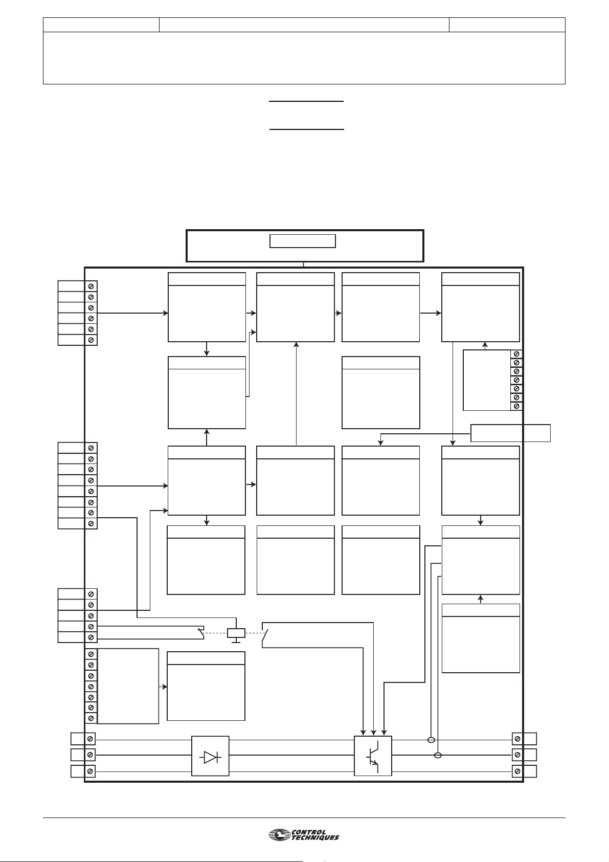
MENU ORGANISATION
MENU 0
See installation and maintenance manual Ref. 3840
3854 en - 03.2008 / b
10V
ADI1
0V
ADI2
0V
ADIO3
DIO1
24V
DI2
DI3
24V
DI4
SDI1
SDI2
COM
RL1C
RL1O
SDO1
SDO2
Additional
I/O, fieldbus
or Modbus RTU
option
MENU 7
Configuration
of
analog I/O
MENU 14
PID controller
MENU 8
Configuration
of
digital I/O
MENU 9
Logic functions
(And, Or,
Motorised pot,
binary sum)
MENU 15
Configuration of
additional I/O
or Modbus RTU/
fieldbus
configuration
MENU 1
Speed
reference
and
limiting
MENU 6 MENU 11 MENU 4
Programmable
logic, timers
MENU 12 MENU 16 MENU 5
Math functions,
threshold
detectors,
brake control
MENU 2
Ramps
MENU 10
Drive states
and
diagnostics
User menu,
serial link,
miscellaneous
PLC functions
(Timing, latching,
upcounting/
downcounting)
Alarms, speed
thresholds,
encoder option
and torque
Motor control
(mode, switching
frequency,
characteristics)
parameters
MENU 3
Encoder
option
serial link RJ45
Current
control
MENU 21
Second
motor
L1
L2
L3
4
U
V
W
Page 5
CONTROL TECHNIQUES
ADVANCED USER GUIDE
Commander SX
IP66/Nema 4X variable speed drive
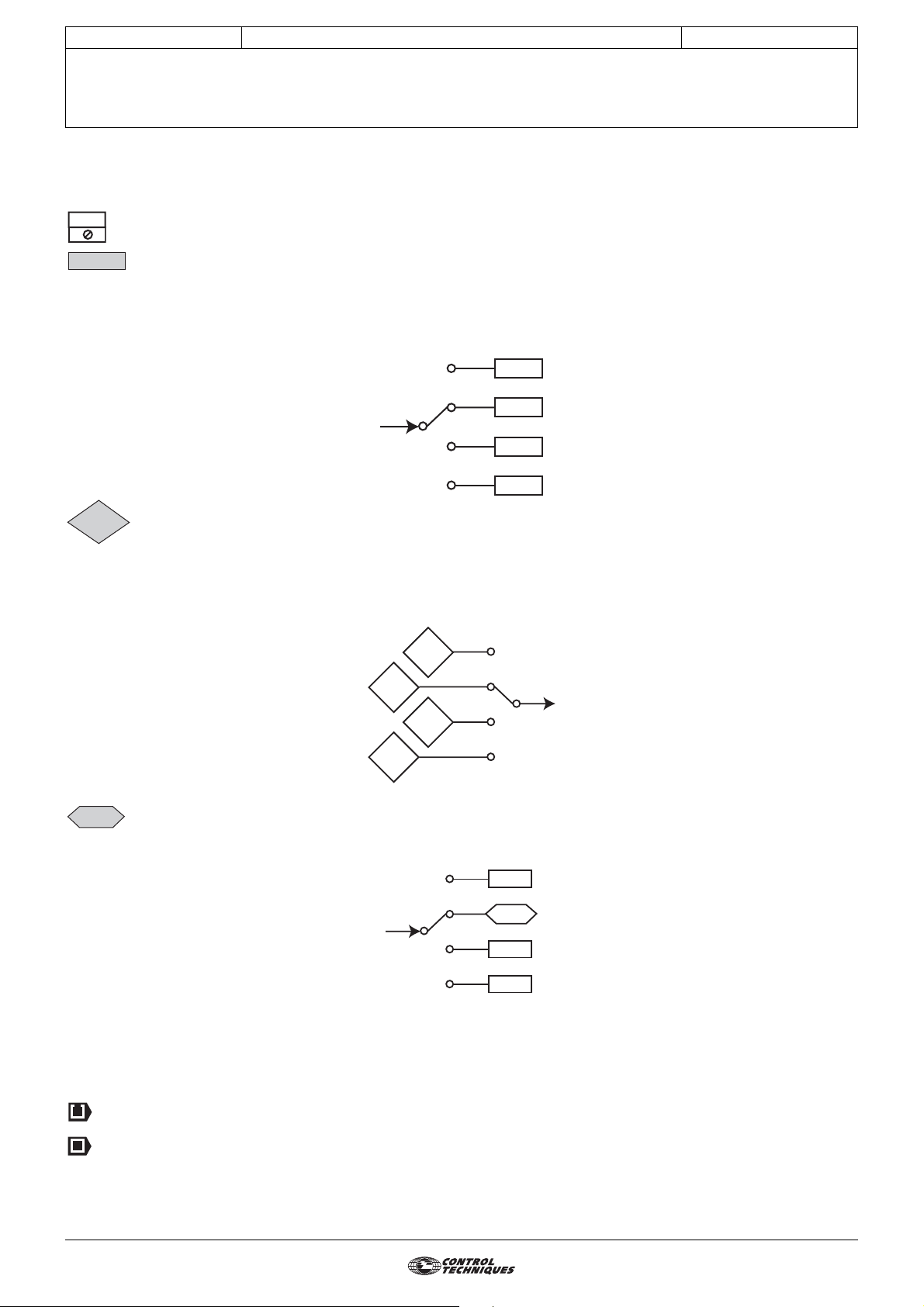
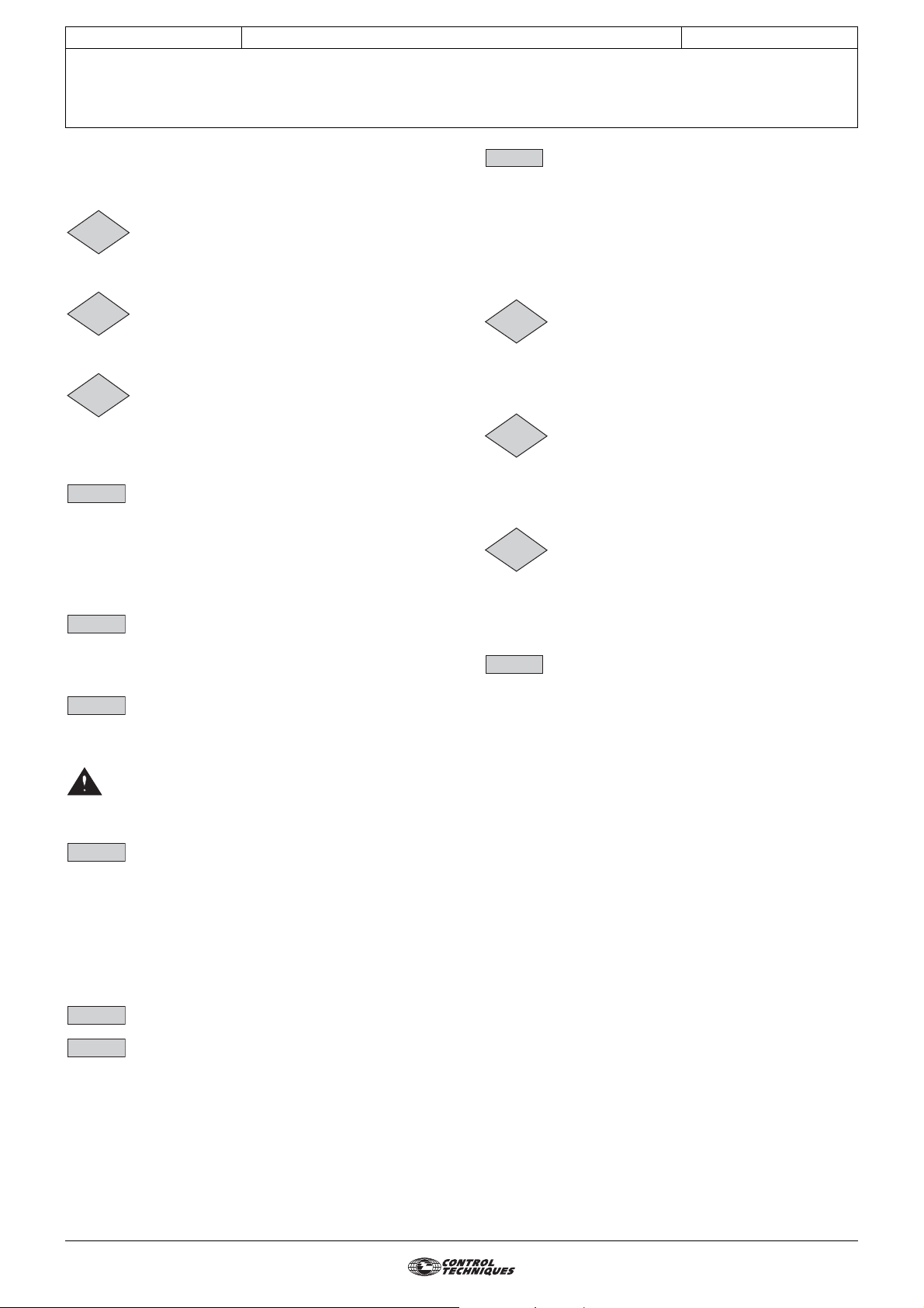
Explanation of symbols used in this document.
1.06 : A shadowed number in bold refers to a parameter.
ADI1
: Refers to a drive input or output terminal.
3854 en - 03.2008 / b
1.21
1.01
: Parameters which appear in a rectangle or identified R-W are parameters with Read and Write access.
They can be designated as an assignment destination for connection to:
- digital inputs for bit parameters
- analog inputs for non-bit parameters
- outputs of internal functions (comparators, logical or arithmetical operations, etc.)
Parameters identified R-W/P cannot be assigned.
: Parameters which appear in a diamond or identified RO/P are parameters with Read Only access which are
write-protected. They are used to provide information concerning operation of the drive and can be designated as an
assignment source for connection to:
- digital outputs for bit parameters
- analog outputs for non-bit parameters
- inputs of internal functions (comparators, logical or arithmetical operations, etc.)
1.36
0 (Disabled) (OFF): The values of "bit" parameters can correspond to a value 0, 1, 2, etc. via the serial link, to a
: Parameters which appear in a hexagon or identified by R-A are parameters which can only be assigned to:
- digital inputs for bit parameters
- analog inputs for non-bit parameters
mnemonic of up to 32 characters using the LCD console, or to a mnemonic of 4
characters maximum using the drive display. These values and labels are given for each
parameter concerned.
: Indicates a parameter used when the drive is configured in open loop Flux Vector Control mode or
U/F.
: Indicates a parameter used when the drive is configured in closed loop Flux Vector Control mode.
5
Page 6

CONTROL TECHNIQUES
ADVANCED USER GUIDE
Commander SX
IP66/Nema 4X variable speed drive
Notes
3854 en - 03.2008 / b
6
Page 7

CONTROL TECHNIQUES
ADVANCED USER GUIDE
3854 en - 03.2008 / b
Commander SX
IP66/Nema 4X variable speed drive
CONTENTS
1 - PARAMETER SETTING USING THE LCD KEYPAD ....................................................................................................9
1.1 - Presentation ....................................................................................................................................................................9
1.2 - Connection to the drive....................................................................................................................................................9
1.3 - Architecture ...................................................................................................................................................................10
1.3.1 - Read mode............................................................ ................................. ...........................................................11
1.3.2 - Simplified parameter-setting mode (menu 0) ...................................................................................................12
1.3.3 - Advanced parameter setting mode (menus 1 to 21).........................................................................................12
1.4 - Commissioning using simplified parameter-setting mode..............................................................................................12
2 - MENU 0 CORRESPONDENCE AND AUTOMATIC PARAMETER SETTING ............................................................13
2.1 - Parameters 01 to 10 ...................................................................................................................................................13
2.2 - Parameters 11 to 24: preset configurations .................................................................................................................13
2.2.1 - Configuration 0: 05 = A1.A2 ..................................... .................................. .................................. .. .................13
2.2.2 - Configuration 1: 05 = A1.Pr ................................................................................... .................................. ........13
2.2.3 - Configuration 2: 05 = A2.Pr ................................................................................... .................................. ........14
2.2.4 - Configuration 3: 05 = 4Pr ............................................................................................ ....................................14
2.2.5 - Configuration 4: 05 = 8Pr ............................................................................................ ....................................15
2.2.6 - Configuration 5: 05 = E.Pot ...................................... ... .................................. ................................. ... ..............15
2.2.7 - Configuration 6: 05 = TorQ .............................................................. .. .................................. ............................16
2.2.8 - Configuration 7: 05 = Pid ............................................................................................... ... ...............................16
2.2.9 - Configuration 8: 05 = Pump .................... .................................. .................................. ....................................17
2.2.10 - Configuration 9: 05 = A.CtP ..........................................................................................................................18
2.2.11 - Configuration 10: 05 = HoiS ..........................................................................................................................18
2.2.12 - Configuration 11: 05 = Pad ...........................................................................................................................19
2.2.13 - Configuration 12: 05 = HuAC ........................................................................................................................19
2.3 - Parameter 25 to 35 ......................................................................................................................................................20
2.4 - Parameters 36 to 80 ....................................................................................................................................................20
3 - MENU 1: SPEED REFERENCE: SELECTION, LIMITING AND FILTERS................................................................... 21
3.1 - List of parameters in Menu 1 .........................................................................................................................................21
3.2 - Menu 1 diagram ............................................................................................................................................................24
3.2.1 - Selection of reference (speed) .........................................................................................................................24
3.2.2 - Limiting and filters ....................................... .................................. ... .. ..............................................................25
3.3 - Explanation of parameters in Menu 1 ............................................................................................................................26
4 - MENU 2: RAMPS ..........................................................................................................................................................31
4.1 - List of parameters in Menu 2 .........................................................................................................................................31
4.2 - Menu 2 diagrams ...........................................................................................................................................................32
4.2.1 - Acceleration ramps ..........................................................................................................................................32
4.2.2 - Deceleration ramps ..........................................................................................................................................33
4.3 - Explanation of parameters in Menu 2 ............................................................................................................................34
5 - MENU 3: FREQUENCY THRESHOLDS - ENCODER OPTION ..................................................................................37
5.1 - List of parameters in Menu 3 .........................................................................................................................................37
5.2 - Menu 3 diagram ............................................................................................................................................................40
5.2.1 - Basic version ....................................................................................................................................................40
5.2.2 - With encoder option .........................................................................................................................................42
5.3 - Explanation of parameters in Menu 3 ............................................................................................................................44
6 - MENU 4: CURRENT AND TORQUE CONTROL..........................................................................................................47
6.1 - List of parameters in Menu 4 .........................................................................................................................................47
6.2 - Menu 4 diagram ............................................................................................................................................................48
6.2.1 - Basic version ....................................................................................................................................................48
6.2.2 - With encoder option .........................................................................................................................................49
6.3 - Explanation of parameters in Menu 4 ............................................................................................................................50
7 - MENU 5: MOTOR CONTROL .......................................................................................................................................53
7.1 - List of parameters in Menu 5 .........................................................................................................................................53
7.2 - Menu 5 diagram ............................................................................................................................................................55
7.3 - Explanation of parameters in Menu 5 ............................................................................................................................56
7.4 - Factory settings according to the rating .........................................................................................................................60
8 - MENU 6: PROGRAMMABLE LOGIC AND TIMERS....................................................................................................61
8.1 - List of parameters in Menu 6 .........................................................................................................................................61
8.2 - Menu 6 diagrams ...........................................................................................................................................................62
8.2.1 - Programmable logic .........................................................................................................................................62
8.2.2 - Timer, energy meter and alarms ......................................................................................................................63
8.2.3 - Downstream contact management ..................................................................................................................63
8.3 - Explanation of parameters in Menu 6 ............................................................................................................................64
9 - MENU 7: ASSIGNMENT OF ANALOG INPUTS AND OUTPUTS................................................................................69
9.1 - List of parameters in Menu 7 .........................................................................................................................................69
9.2 - Menu 7 diagram ............................................................................................................................................................70
9.2.1 - Assignment of analog I/O .................................................................................................................................70
9.2.2 - Scaling block ....................................................................................................................................................70
9.2.3 - Temperature indications ...................................................................................................................................70
9.3 - Explanation of parameters in Menu 7 ............................................................................................................................71
7
Page 8

CONTROL TECHNIQUES
ADVANCED USER GUIDE
3854 en - 03.2008 / b
Commander SX
IP66/Nema 4X variable speed drive
CONTENTS
10 - MENU 8: ASSIGNMENT OF DIGITAL INPUTS AND OUTPUTS...............................................................................75
10.1 - List of parameters in Menu 8 .......................................................................................................................................75
10.2 - Menu 8 diagrams .........................................................................................................................................................77
10.2.1 - Assignment of digital inputs and the relay output ...........................................................................................77
10.2.2 - Local controls .................................................................................................................................................78
10.3 - Explanation of parameters in Menu 8 ..........................................................................................................................79
11 - MENU 9: LOGIC FUNCTIONS, MOTORISED POT AND BINARY SUM ..................................................................83
11.1 - List of parameters in Menu 9 .......................................................................................................................................83
11.2 - Menu 9 diagrams .........................................................................................................................................................84
11.2.1 - Logic functions ...............................................................................................................................................84
11.2.2 - Motorised pot function ................................................................. ...................................................................84
11.2.3 - Binary sum function ........................................................................................................................................84
11.3 - Explanation of parameters in Menu 9 ..........................................................................................................................85
12 - MENU 10: DRIVE STATES AND DIAGNOSTICS ......................................................................................................87
12.1 - List of parameters in Menu 10 .....................................................................................................................................87
12.2 - Menu 10 diagrams .......................................................................................................................................................90
12.2.1 - Operating states ................................ .............................................................................................................90
12.2.2 - Braking resistor and trip management configuration ......................................................................................91
12.3 - Explanation of parameters in Menu 10 ........................................................................................................................92
13 - MENU 11: SERIAL LINK - DRIVE CHARACTERISTICS - MISCELLANEOUS.........................................................97
13.1 - List of parameters in Menu 11 .....................................................................................................................................97
13.2 - Menu 11 diagram ........................................................................................................................................................99
13.3 - Explanation of parameters in Menu 11 ......................................................................................................................100
14 - MENU 12: THRESHOLD DETECTORS, VARIABLE SELECTORS AND BRAKE CONTROL FUNCTION............105
14.1 - List of parameters in Menu 12 ...................................................................................................................................105
14.2 - Menu 12 diagrams .....................................................................................................................................................106
14.2.1 - Comparators ................................................................................................................................................106
14.2.2 - Variable selectors .........................................................................................................................................106
14.2.3 - Brake control in open loop mode .................................................................................................................107
14.2.4 - Brake control in closed loop mode ...............................................................................................................108
14.3 - Explanation of parameters in Menu 12 ......................................................................................................................109
15 - MENU 13: RESERVED .............................................................................................................................................113
16 - MENU 14: PID CONTROLLER .................................................................................................................................115
16.1 - List of parameters in Menu 14 ...................................................................................................................................115
16.2 - Menu 14 diagram ......................................................................................................................................................116
16.3 - Explanation of parameters in Menu 14 ......................................................................................................................117
17 - MENU 15: MODBUS RTU AND FIELDBUS CONNECTION OPTIONS, AND ADDITIONAL I/O ...........................119
18 - MENU 16: PLC FUNCTIONS ....................................................................................................................................121
18.1 - List of parameters in Menu 16 ...................................................................................................................................121
18.2 - Menu 16 diagrams .....................................................................................................................................................122
18.2.1 - Timer relays .................................................................................................................................................122
18.2.2 - Latching relays .............................................................................................................................................122
18.2.3 - Counter ........................................................................................................................................................123
18.3 - Explanation of parameters in Menu 16 ......................................................................................................................124
19 - MENUS 17 TO 20: RESERVED ...............................................................................................................................127
20 - MENU 21: OPERATING PARAMETERS FOR A SECOND MOTOR.......................................................................129
20.1 - List of parameters in Menu 21 ...................................................................................................................................129
20.2 - Explanation of parameters in Menu 21 ......................................................................................................................130
21 - OPERATION WITH MODBUS RTU .........................................................................................................................133
21.1 - Serial link ................................. .................................. ... ... ................................. .........................................................133
21.1.1 - Location and connection ..............................................................................................................................133
21.1.2 - Protocols ........................................ ... ...........................................................................................................133
21.1.3 - Parameter setting..........................................................................................................................................133
21.1.4 - Networking ...................................................................................................................................................133
21.2 - Parameter setting using the PC ................................ ... ................................. ... .........................................................133
21.3 - Control word and status word ....................................................................................................................................133
21.4 - MODBUS RTU ..........................................................................................................................................................134
21.4.1 - General information.......................................................................................................................................134
21.4.2 - Description of exchanges .............................................................................................................................134
21.4.3 - Parameter assignment .................................................................................................................................135
21.4.4 - Data encoding ..............................................................................................................................................135
21.4.5 - Function codes .............................................................................................................................................135
21.4.6 - Example ......................................... ..............................................................................................................137
21.4.7 - Wait time ......................................................................................................................................................137
21.4.8 - Exceptions ....................................................................................................................................................137
21.4.9 - CRC .............................................................................................................................................................137
8
Page 9
CONTROL TECHNIQUES
ADVANCED USER GUIDE
Commander SX
IP66/Nema 4X variable speed drive
PARAMETER SETTING USING THE LCD KEYPAD
3854 en - 03.2008 / b
1 - PARAMETER SETTING USING THE LCD KEYPAD
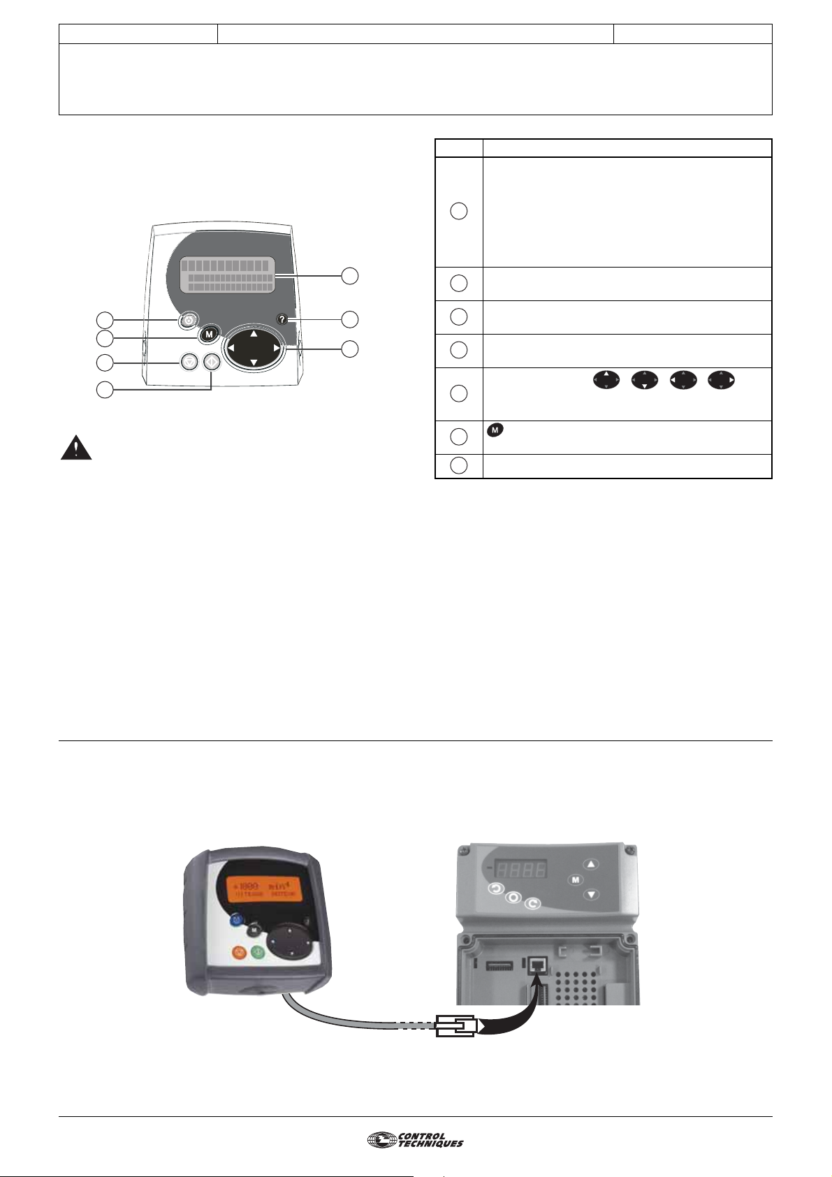
1.1 - Presentation
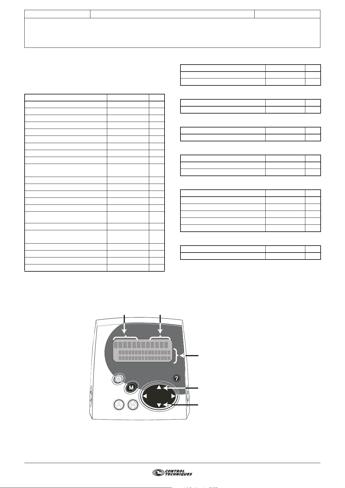
A
D
F
C
B
• The drives use an algorithm which is adjusted by
parameters. The performance levels obtained
depend on the parameter setting. Inappropriate settings
may have serious consequences for personnel and
machinery.
• The drive parameters must only be set by
appropriately qualified and experienced personnel.
• Before powering up the drive, check that the
power connections (mains supply and motor) are
correct, and that any moving parts are mechanically
protected.
• Before setting the drive parameters, all
instructions relating to installation and connection of the
drive contained in the installation document must have
been followed to the letter (see manual supplied with the
drive).
• Users of the drive should take particular care to
avoid starting it accidentally.
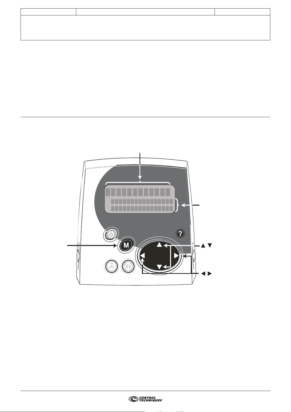
G
E
Ref. Function
Backlit LCD with a 3-line display for indicating:
- The drive operating status and its main data
- The main adjustment parameters via a
A
"simplified parameter setting" menu (menu 0)
- All drive parameters via 21 menus for
"advanced parameter setting" (access via a code)
Green key for run command if control via the
B
keypad is enabled (see 6.43).
Red button for drive reset (RESET) and stop
C
command.
Blue button for change of direction of rotation if
D
control via the keypad is enabled (see 6.43).
Navigation button ( , , , ) for
E
moving through the various menus and changing
the contents of parameters.
F
G
button for saving and changing the mode
(display, read, set parameters).
? button not used.
1.2 - Connection to the drive
The parameter-setting keypad connects to the Commander SX with a male/male RJ45 - RJ45 shielded cable.
The drive automatically detects the presence of the LCD keypad.
9
Page 10
CONTROL TECHNIQUES
ADVANCED USER GUIDE
3854 en - 03.2008 / b
Commander SX
IP66/Nema 4X variable speed drive
PARAMETER SETTING USING THE LCD KEYPAD
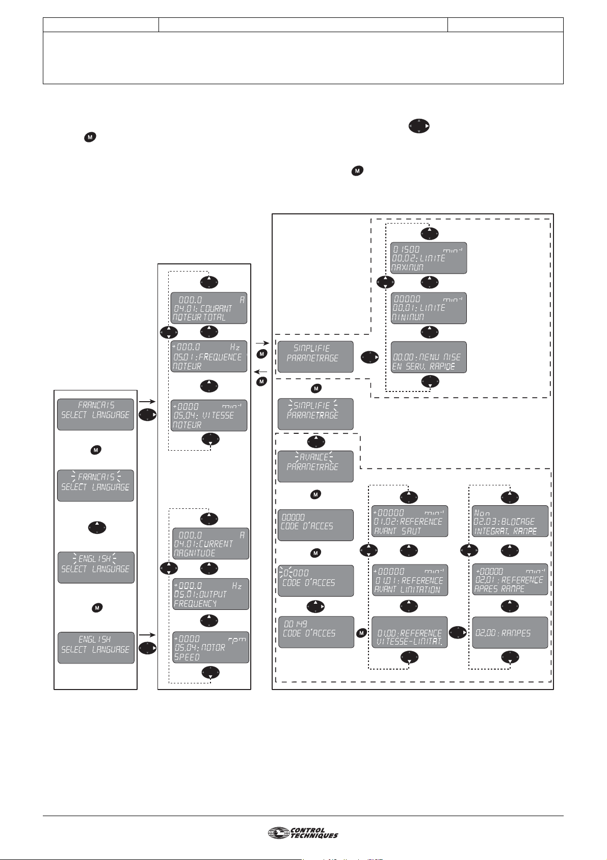
1.3 - Architecture
On power-up, the keypad offers a choice of languages (factory setting: French). Press the key to access read mode. Then
press the key to access parameter-setting mode; there are 2 parameter-setting levels:
- "Simplified" parameter setting (user menu, known as menu 0)
- "Advanced" parameter setting (menus 1 to 21), protected by an access code (factory setting = 149)
To return from parameter-setting mode to read mode, simply hold down the button for a few seconds.
Basic architecture
Parameter-setting mode
Simplied parameter
setting (menu 0)
Read mode
Language selection
5 sec
Advanced parameter setting (menus 1 --> 21)
10
Page 11
CONTROL TECHNIQUES
r
ADVANCED USER GUIDE
Commander SX
IP66/Nema 4X variable speed drive
PARAMETER SETTING USING THE LCD KEYPAD
3854 en - 03.2008 / b
1.3.1 - Read mode
Read mode is used to display the status of the drive an d its
main measurement points when stopped or during operation.
1.3.1.1 - List of displayed parameters
Name Address Unit
MOTOR SPEED 5.04 rpm
MOTOR FREQUENCY 5.01 Hz
TOTAL MOTOR CURRENT 4.01 A
ACTIVE CURRENT 4.02 A
OUTPUT VOLTAGE 5.02 V
DC BUS VOLTAGE 5.05 V
ANALOG INPUT 1 7.01 %
ANALOG INPUT 2 7.02 %
ANALOG/DIG./PTC INPUT 3 7.03 %
DIGITAL IN/OUT 1 to 4 STATE
+ SDI
RELAY + BRAKE OUTPUT 8.07 and 12.40 -
SELECTED REFERENCE 1.49 -
SELECTED PRESET REFERENCE 1.50 -
SPEED REFERENCE SELECTED 1.01 rpm
POST-RAMP REFERENCE 2.01 rpm
RUN COUNTER: YEARS/DAYS,
Hr/Min
ENERGY METER: MWh, KWh 6.24 and 6.25 -
TRIP -2 to
TRIP -10
Drive SOFTWARE VERSION 11.29 -
LCD KEYPAD VERSION - MAX DRIVE CURRENT RATING 11.32 -
LAST PRESET CONFIG. 11.48 -
8.01 to 8.07 -
6.22 and 6.23 -
10.21 to
10.29
-
• Configuration of A1.A2:
Name Address Unit
ANALOG REFERENCE 2 1.37 rpm
ANALOG REFERENCE 1 1.36
• Configuration of A1.Pr and A2.Pr:
Name Address Unit
ANALOG REFERENCE 1 1.36
• Configuration of E.Pot:
Name Address Unit
MOTORISED POT. REFERENCE 9.03
• Configuration of Torq:
Name Address Unit
ANALOG REFERENCE 1 1.36 rpm
TORQUE REFERENCE 4.08
• Configuration of PID and PUMP:
Name Address Unit
PID REFERENCE 14.20 %
PID FEEDBACK 14.21 %
PID MAIN REFERENCE 14.19 %
PID ERROR 14.22 %
PID OUTPUT VALUE 14.01 %
• Configuration of PAD:
Name Address Unit
REFERENCE VIA KEYPAD 1.17
rpm
rpm
rpm
%
%
1.3.1.2 - Basic display
Signed value Unit
+1500
0
5.04:
SPEED
MO TOR
mpr
Parameter address and name
Display the next parameter
Display the previous paramete
11
Page 12
CONTROL TECHNIQUES
ADVANCED USER GUIDE
Commander SX
IP66/Nema 4X variable speed drive
PARAMETER SETTING USING THE LCD KEYPAD
3854 en - 03.2008 / b
1.3.2 - Simplified parameter setting mode (menu 0)
A user menu, known as menu 0, contains the most useful
parameters. Each parameter in menu 0 is the image of a
parameter contained in another menu in advanced
parameter-setting mode.
The drive has 21 menus (menu 1 to menu 21).
A parameter is indicated by XX.YY, where the first two figures
(XX) refer to the menu and the next two figures (YY) refer to
the parameter number in the menu.
The change from simplified parameter setting mode to
advanced parameter setting mode is protected by an access
code (factory setting: 149).
1.3.3 - Advanced parameter setting mode (menus 1 to 21)
Advanced parameter setting mode provides access to all the
drive parameters. The parameters are arranged in menus.
1.4 - Commissioning using simplified parameter setting mode
Parameter value
Press once to change
the value of the selected
parameter.
The second press on
the button is used to
confirm the modification
and access the other
parameters.
1500
0
1.06:
REFEREN
rmp
AMXIMU
CLAMP
C
E
M
Parameter number and name
, are used to select the
menu 0 parameter to be modified
or to increment/decrement the
value of the parameter currently
being modified.
, are used to exit
parameter-setting mode or to move
the cursor when modifying a value.
12
Page 13
CONTROL TECHNIQUES
MENU 0 CORRESPONDENCE AND AUTOMATIC PARAMETER SETTING
ADVANCED USER GUIDE
Commander SX
IP66/Nema 4X variable speed drive
3854 en - 03.2008 / b
2 - MENU 0 CORRESPONDENCE AND AUTOMATIC PARAMETER SETTING
This section describes the interactions between menu 0 (user
menu) and the advanced menus (menus 1 to 21).
On the one hand, each parameter in menu 0 (01 to 80) is in
fact the image (address) of a parameter in the advanced
menus (e.g. parameter 02 corresponds to parameter 1.06 in
menu 1).
On the other hand, when a preset configuration is selected by
parameter 05, the drive automatically assigns parameters 11
to 24 of menu 0 to adapt the drive to the application, and also
then internally sets a list of parameters (different depending
on the selected preset configuration).
It is therefore useful to know these internal settings in cases
where the user starts parameter setting via menu 0, and ends
with the advanced menus.
Refer to the installation and commissioning manual ref. 3840
for commissioning using menu 0.
2.2 - Parameters 11 to 24: preset configurations
2.2.1 - Configuration 0: 05 = A1.A2
Parameter Name Address
11 ADI1 mode 7.06
12 ADI2 mode 7.11
13
24
• Internal setting
Parameter Name Value
1.14 Reference selector 0
6.04 Start/stop logic select 0
7.06 ADI1 mode 6
7.08 ADI1 input scaling 1 0 0
7.09 ADI1 input invert 0
7.10 ADI1 input destination 1.36
7.11 ADI2 mode 4
7.12 ADI2 input scaling 1 0 0
7.13 ADI2 input invert 0
7.14 ADI2 input destination 1.37
7.15 ADIO3 mode 10
7.16 ADIO3 scaling 1 0 0
7.17 ADIO3 input invert 0
7.18 ADIO3 input destination/output source 5.04
8.10 Secure disable select 1
8.11 DIO1 input or output invert 0
8.12 DI2 input invert 0
8.13 DI3 input invert 0
8.14 DI4 input invert 0
8.17 Output relay invert 0
8.21 DIO1 input destination/output source 10.03
8.22 DI2 input destination 6.30
8.23 DI3 input destination 6.32
8.24 DI4 input destination 1.41
8.27 Output relay source 10.01
8.31 DIO1 input or output select 1
Not used
to
WARNING:
The purpose of the preset configurations in menu 0 is to
adapt the drive to the application as closely as possible.
However, if the user changes the structure of the
selected preset configuration by adding settings via the
advanced menus, the 05 parameter changes to "OPEn"
(unrestricted parameter setting).
2.1 - Parameters 01 to 10
Parameter Name Address
01
02 Maximum reference clamp 1.06
03 Acceleration rate 2.11
04 Deceleration rate 2.21
05 Preset configuration select 11.46
06 Motor rated current 5.07
07 Motor rated speed 5.08
08 Motor rated voltage 5.09
09 Rated power factor (cos ϕ) 5.10
10 Quick setup menu access 11.44
2.2.2 - Configuration 1: 05 = A1.Pr
Parameter Name Address
11 ADI1 mode 7.06
12 Preset reference 2 1.22
13 Preset reference 3 1.23
14 Preset reference 4 1.24
15
to
24
• Internal setting
Parameter Name Value
1.14 Reference selector 1
1.15 Preset selector 0
6.04 Start/stop logic select 0
6.43 Run/Stop source 0
7.06 ADI1 mode 6
7.09 ADI1 input invert 0
7.10 ADI1 input destination 1.36
7.11 ADI2 mode 7
7.13 ADI2 input invert 0
7.14 ADI2 input destination 1.46
7.15 ADIO3 mode 10
7.17 ADIO3 input invert 0
7.18 ADIO3 input destination/output source 5.04
7.33 AIO3 feature 0
8.10 Secure disable select 1
8.11 DIO1 input or output invert 0
8.12 DI2 input invert 0
8.13 DI3 input invert 0
8.14 DI4 input invert 0
8.17 Output relay invert 0
8.21 DIO1 input destination/output source 10.03
8.22 DI2 input destination 6.30
8.23 DI3 input destination 6.32
8.24 DI4 input destination 1.45
8.27 Output relay source 10.01
8.31 DIO1 input or output select 1
8.41 DIO1 feature 0
Minimum reference clamp
Not used
1.07
13
Page 14
CONTROL TECHNIQUES
MENU 0 CORRESPONDENCE AND AUTOMATIC PARAMETER SETTING
ADVANCED USER GUIDE
Commander SX
IP66/Nema 4X variable speed drive
3854 en - 03.2008 / b
2.2.3 - Configuration 2: 05 = A2.Pr
Parameter Name Address
11 ADI1 mode 7.06
12 Preset reference 2 1.22
13 Preset reference 3 1.23
14 Preset reference 4 1.24
15
Not used
to
24
• Internal setting
Parameter Name Value
1.14 Reference selector 1
1.15 Preset selector 0
6.04 Start/stop logic select 0
6.43 Run/Stop source 0
7.06 ADI1 mode 4
7.09 ADI1 input invert 0
7.10 ADI1 input destination 1.36
7.11 ADI2 mode 7
7.13 ADI2 input invert 0
7.14 ADI2 input destination 1.46
7.15 ADIO3 mode 10
7.17 ADIO3 input invert 0
7.18 ADIO3 input destination/output source 5.04
7.33 ADIO3 feature 0
8.10 Secure disable select 1
8.11 DIO1 input or output invert 0
8.12 DI2 input invert 0
8.13 DI3 input invert 0
8.14 DI4 input invert 0
8.17 Output relay invert 0
8.21
8.22 DI2 input destination 6.30
8.23 DI3 input destination 6.32
8.24 DI4 input destination 1.45
8.27 Output relay source 10.01
8.31 DIO1 input or output select 1
8.41 DIO1 feature 0
DIO1 input destination/output source
10.03
2.2.4 - Configuration 3: 05 = 4Pr
Parameter Name Address
11 Preset reference 1 1.21
12 Preset reference 2 1.22
13 Preset reference 3 1.23
14
15
24
• Internal setting
Parameter Name Value
1.14 Reference selector 3
1.15 Preset selector 0
6.04 Start/stop logic select 0
6.43 Run/Stop source 0
7.06 ADI1 mode 7
7.09 ADI1 input invert 0
7.10 ADI1 input destination 1.46
7.11 ADI2 mode 8
7.13 ADI2 input invert 0
7.15 ADIO3 mode 10
7.17 ADIO3 input invert 0
7.18
7.33 ADIO3 feature 0
8.10 Secure disable select 1
8.11 DIO1 input or output invert 0
8.12 DI2 input invert 0
8.13 DI3 input invert 0
8.14 DI4 input invert 0
8.17 Output relay invert 0
8.21
8.22 DI2 input destination 6.30
8.23 DI3 input destination 6.32
8.24 DI4 input destination 1.45
8.27 Output relay source 10.01
8.41 DIO1 feature 0
Preset reference 4 1.24
to
Not used
ADIO3 input destination/output source
DIO1 input destination/output source
5.04
10.03
14
Page 15
CONTROL TECHNIQUES
MENU 0 CORRESPONDENCE AND AUTOMATIC PARAMETER SETTING
ADVANCED USER GUIDE
Commander SX
IP66/Nema 4X variable speed drive
3854 en - 03.2008 / b
2.2.5 - Configuration 4: 05 = 8Pr
Parameter Name Address
11
12 Preset reference 2 1.22
13 Preset reference 3 1.23
14 Preset reference 4 1.24
15 Preset reference 5 1.25
16 Preset reference 6 1.26
17 Preset reference 7 1.27
18 Preset reference 8 1.28
19
24
• Internal setting
Parameter Name Value
1.14 Reference selector 3
1.15 Preset selector 0
6.04 Start/stop logic select 0
6.43 Run/Stop source 0
7.06 ADI1 mode 7
7.09 ADI1 input invert 0
7.10 ADI1 input destination 1.46
7.11 ADI2 mode 7
7.13 ADI2 input invert 0
7.14 ADI2 input destination 1.47
7.15 ADIO3 mode 10
7.17 ADIO3 input invert 0
7.18 ADIO3 input destination/output source 5.04
7.33 ADIO3 feature 0
8.10 Secure disable select 1
8.11 DIO1 input or output invert 0
8.12 DI2 input invert 0
8.13 DI3 input invert 0
8.14 DI4 input invert 0
8.17 Output relay invert 0
8.21 DIO1 input destination/output source 10.03
8.22 DI2 input destination 6.30
8.23 DI3 input destination 6.32
8.24 DI4 input destination 1.45
8.27 Output relay source 10.01
8.31 DIO1 input or output select 1
8.41 DIO1 feature 0
Preset reference 1
Not used
to
1.21
2.2.6 - Configuration 5: 05 = E.Pot
Parameter Name Address
11
12
13
14
15
16
17
18
24
• Internal setting
Parameter Name Value
1.09 R ef er en ce o ff se t va l id at ion 1
1.14 Reference selector 1
6.04 S ta rt /s to p lo gic s el ec t 0
6.43 Run/Stop source 0
7.06 A DI 1 mo de 6
7.09 ADI1 input invert 0
7.10 ADI1 input destination 1.36
7.11 ADI2 mode 7
7.13 A DI 2 in pu t in vert 0
7.14 ADI2 input destination 9.26
7.15 A DI O3 m ode 10
7.17 ADIO3 input invert 0
7.18 ADIO3 input destination/output source 5.04
7.33 ADIO3 feature 0
8.10 S ec ur e di sa bl e se l ec t 1
8.11 DIO1 input or output invert 0
8.12 D I2 i np ut i nv ert 0
8.13 DI3 input invert 0
8.14 D I4 i np ut i nv ert 0
8.17 Output relay invert 0
8.21 DIO1 input destination/output source 10.03
8.22 DI2 input destination 6.30
8.23 DI3 input destination 6.32
8.24 DI4 input destination 9.27
8.27 Output relay source 10.01
8.31
8.41
9.25
ADI1 mode
Manual motorised pot reset
Automatic motorised pot reset
Motorised pot bipolar select
Motorised pot rate
Motorised pot scale factor
Motorised pot reference
Not usedto
DIO1 input or output select 1
DI O 1 fe at ur e 0
Motorised pot destination 1.04
7.06
9.28
9.21
9.22
9.23
9.24
9.03
15
Page 16
CONTROL TECHNIQUES
MENU 0 CORRESPONDENCE AND AUTOMATIC PARAMETER SETTING
ADVANCED USER GUIDE
Commander SX
IP66/Nema 4X variable speed drive
3854 en - 03.2008 / b
2.2.7 - Configuration 6: 05 = TorQ
Parameter Name Address
11
12 ADI2 mode 7.11
13
18
19 ADI2 scaling 7.12
20
24
• Internal setting
Parameter Name Value
1.14 Reference selector 1
6.04 Start/stop logic select 0
6.43 Run/Stop source 0
7.06 ADI1 mode 6
7.09 ADI1 input invert 0
7.10 ADI1 input destination 1.36
7.11 ADI2 mode 6
7.13 ADI2 input invert 0
7.14 ADI2 input destination 4.08
7.15 ADIO3 mode 10
7.17 ADIO3 input invert 0
7.18 ADIO3 input destination/output source 5.04
7.33 ADIO3 feature 0
8.10 Secure disable select 1
8.12 DI2 input invert 0
8.13 DI3 input invert 0
8.14 DI4 input invert 0
8.17 Output relay invert 0
8.21 DIO1 input destination/output source 10.03
8.22 DI2 input destination 6.30
8.23 DI3 input destination 6.32
8.24 DI4 input destination 4.11
8.27 Output relay source 10.01
8.31 DIO1 input or output select 1
8.41 DIO1 feature 0
ADI1 mode 7.06
Not usedto
Not usedto
2.2.8 - Configuration 7: 05 = Pid
Parameter Name Address
11 ADI1 mode
12
13
14
15
16
17
18
19
20
21
22
23
24
• Internal setting
Parameter Name Value
1.14 R ef er en ce s el ec tor 1
6.04 Start/stop logic select 0
6.43 R un /S to p so ur ce 0
7.06 ADI1 mode 6
7.09 A DI 1 in pu t in vert 0
7.10 ADI1 input destination 1.27
7.11 A DI 2 mo de 2
7.13 ADI2 input invert 0
7.14 ADI2 input destination 1.28
7.15 ADIO3 mode 6
7.17 ADIO3 input invert 0
7.18
7.33 A DI O3 f ea tu re 4
8.10 Secure disable select 1
8.11 DIO1 input or output invert 0
8.12 DI2 input invert 0
8.13 D I3 i np ut i nv ert 0
8.14 DI4 input invert 0
8.17 O ut pu t re la y inve r t 0
8.21
8.22 DI2 input destination 6.30
8.23 DI3 input destination 6.32
8.24 DI4 input destination 14.08
8.27 Output relay source 10.01
8.31 DIO1 input or output select 1
8.41 DIO1 feature 2
14.02 PID main reference source 1.26
14.03 PID reference source 1.27
14.04 PID feedback source 1.28
14.16 PID output destination 1.36
ADI2 mode 7.11
PID proportional gain
PID integral gain
PID derivative gain
PID upper limit
PID lower limit
PID output scaling
ADI2 input scaling
ADIO3 input scaling
PID reference
PID feedback
PID main reference
PID output
ADIO3 input destination/output source
DIO1 input destination/output source
7.06
14.10
14.11
14.12
14.13
14.14
14.15
7.12
7.16
14.20
14.21
14.19
14.01
1.26
10.04
16
Page 17
CONTROL TECHNIQUES
MENU 0 CORRESPONDENCE AND AUTOMATIC PARAMETER SETTING
ADVANCED USER GUIDE
Commander SX
IP66/Nema 4X variable speed drive
3854 en - 03.2008 / b
2.2.9 - Configuration 8: 05 = Pump
Parameter Name Address
11
12 ADI2 mode 7.11
13
14 PID integral gain 14.11
15 Stop on Vmin enable 14. 56
16
17 Draining time delay 16.05
18 Digital reference 14.51
19
20 Reference input in customer units 14.54
21 Sensor input in customer units 14.55
22
23
24
• Internal setting
Parameter Name Value
5.09 Motor rated voltage 40 0
7.06 ADI1 mode 6
7.10 ADI1 input destination 1.23
7.11 ADI2 mode 2
7.14 ADI2 input destination 1.24
7.15 ADIO3 mode 10
7.18 ADIO3 input destination/output source 10.90
7.33 ADIO3 feature 4
7.62 Block scaling 1 0 5
7.64 Scaling block destinati on 12.24
7.68 Scaling block source 12.12
8.11 DIO1 input or output invert 1
8.14 DI4 input invert 0
8.21 DIO1 input destination/output source 10.63
8.22 DI2 input destination 9.30
8.23 DI3 input destination 12.10
8.24 DI4 input destination 1.42
8.31 DIO1 input or output select 0
8.41 DIO1 feature 9
9.04 Logic function 1 source 1 12.01
9.06 Logic function 1 source 2 8.02
9.14 Logic function 2 source 1 9.01
9.16 Logic function 2 source 2 8.04
9.33 Binary sum destination 0
9.34 Binary sum output offset 0
9.64 Logic function 3 source 1 12.02
9.65 Logic function 3 source 1 invert 1
9.66 Logic function 3 source 2 14.56
9.74 Logic function 4 source 1 9.61
9.75 Logic function 4 source 1 invert 1
9.76 Logic function 4 source 2 14.56
9.78 Logic function 4 output invert 1
ADI1 mode 7.06
PID proportional gain
Draining threshold
Customer unit scaling coefficient
Motor speed
Not usedand
14.10
12.04
14.53
5.04
Parameter Name Value
11.01 Parameter 46 set-up 6.22
11.02 Parameter 47 set-up 6.23
11.03 Parameter 48 set-up 7.62
11.04 Parameter 49 set-up 10.20
11.05 Parameter 50 set-up 10.21
11.06 Parameter 51 set-up 10.22
11.07 Parameter 52 set-up 10.23
11.08 Parameter 53 set-up 10.24
11.09 Parameter 54 set-up 10.25
11.10 Parameter 55 set-up 10.26
11.11 Parameter 56 set-up 10.27
11.12 Parameter 57 set-up 10.28
11.13 Parameter 58 set-up 10.29
11.44 Quick setup menu access 1
12.03 Comparator 1 source 1.24
12.04 Comparator 1 threshold 200
12.05 Comparator 1 hysteresis 20
12.06 Comparator 1 output invert 1
12.08 Function 1 variable 1 source 1.23
12.09 Function 1 variable 2 source 1.22
12.11 Function 1 output destination 1.21
12.23 Comparator 2 source 1.24
12.25 Comparator 2 hysteresis 10
12.28 Function 2 variable 1 source 14.51
12.29 Function 2 variable 2 source 1.06
12.30 Function block 2 select 4
12.31 Function 2 output destination 1.22
12.33 Function 2 variable 1 scale 1 0
12.63 Comparator 3 source 9.32
12.64 Comparator 3 threshold 64
12.65 Comparator 3 hysteresis 0
12.67 Comparator 3 output destination 6.30
14.02 PID main reference source 1.21
14.03 PID reference source 1.21
14.04 PID feedback source 1.24
14.08 PID enable 1
14.09 PID option enable source 8.04
14.10 PID proportional gain 15000
14.11 PID integral gain 2000
14.16 PID output destination 1.36
14.53 Customer unit coefficient 1
14.56 Stop on V min enable 1
16.02 Timer relay 1 input source 9.02
16.05 Timer relay 1 value 1 0 0
16.09 Timer relay 1 output destination 10.61
16.12 Timer relay 2 input source 9.71
16.13 Ti m er r el ay 2 t yp e 1
16.15 Timer relay 2 value 100
16.19 Timer relay 2 output destination 9.29
17
Page 18

CONTROL TECHNIQUES
MENU 0 CORRESPONDENCE AND AUTOMATIC PARAMETER SETTING
ADVANCED USER GUIDE
Commander SX
IP66/Nema 4X variable speed drive
3854 en - 03.2008 / b
2.2.10 - Configuration 9: 05 = A.CtP
Parameter Name Address
11
Not usedto
24
• Internal setting
Parameter Name Value
1.14 Reference selector 1
6.04 Start/stop logic select 0
6.43 Run/Stop source 0
7.09 ADI1 input invert 0
7.10 ADI1 input destination 1.36
7.11 ADI2 mode 8
7.13 ADI2 input invert 0
7.14 ADI2 input destination 0
7.15 ADIO3 mode 10
7.17 ADIO3 input invert 0
7.18 ADIO3 input destination/output source 5.04
7.33 ADIO3 feature 4
8.10 Secure disable select 1
8.11 DIO1 input or output invert 0
8.12 DI2 input invert 0
8.13 DI3 input invert 0
8.14 DI4 input invert 1
8.17 Output relay invert 0
8.21 DIO1 input destination/output source 10.03
8.22 DI2 input destination 6.30
8.23 DI3 input destination 6.32
8.24 DI4 input destination 9.30
8.27 Output relay source 10.01
8.31 DIO1 input or output select 1
8.41 DIO1 feature 9
9.33 Binary sum destination 7.06
9.34 Binary sum output offset 4
2.2.11 - Configuration 10: 05 = HoiS
Parameter Name Address
11
12 Preset reference 2 (PR2) 1.22
13
24
• Internal setting
Parameter Name Value
1.10 Bipolar reference select 1
1.14 Reference selector 1
2.51 Ramp hold condition 1
6.04 Start/stop logic select 0
6.43 Run/Stop source 0
7.06 ADI1 mode 6
7.09 ADI1 input invert 0
7.10 ADI1 input destination 1.36
7.11 ADI2 mode 8
7.13 ADI2 input invert 0
7.14 ADI2 input destination 0
7.15 ADIO3 mode 7
7.17 ADIO3 input invert 0
7.18 ADIO3 input destination/output source 1.45
7.33 ADIO3 feature 4
8.10 Secure disable select 1
8.11 DIO1 input or output invert 0
8.12 DI2 input invert 0
8.13 DI3 input invert 0
8.14 DI4 input invert 0
8.17 Output relay invert 0
8.21 DIO1 input destination/output source 12.51
8.22 DI2 input destination 6.30
8.23 DI3 input destination 6.32
8.24 DI4 input destination 0
8.27 Output relay source 10.01
8.31 DIO1 input or output select 0
8.41 DIO1 feature 9
9.04 Logic functi on 1 source 1 8.04
9.05 Logic function 1 source 1 invert 1
9.06 Logic functi on 1 source 2 9.02
9.07 Logic function 1 source 2 invert 1
9.08 Logic function 1 output invert 0
9.10 Logic function 1 output destination 2.03
9.14 Logic functi on 2 source 1 1.45
9.16 Logic functi on 2 source 2 10.07
Not used
Not used
to
18
Page 19
CONTROL TECHNIQUES
MENU 0 CORRESPONDENCE AND AUTOMATIC PARAMETER SETTING
ADVANCED USER GUIDE
Commander SX
IP66/Nema 4X variable speed drive
3854 en - 03.2008 / b
2.2.12 - Configuration 11: 05 = Pad
Parameter Name Address
11
12 Power-up keypad reference (Preset 1) 1.21
13
14
15
16
24
• Internal setting
Parameter Name Value
1.14 R ef er en ce s el ec tor 4
6.11 Enable local control FWD key 1
6.12 Enable local control Stop key 1
6.13 Enable keypad REV key 0
6.43 R un /S to p so ur ce 2
7.11 ADI2 mode 8
7.15 A DI O3 m ode 10
7.18 ADIO3 input destination/output source 5.04
7.33 A DI O3 f ea tu re 0
8.10 Secure disable select 0
8.17 O ut pu t re la y inve r t 0
8.22 DI2 input destination 0
8.23 DI3 input destination 6.39
8.24 DI4 input destination 6.13
8.27 Output relay source 10.01
8.81 DIRF input destination 0
8.83 D IR R in pu t de st in atio n 0
Power-up keypad reference
Enable FWD key 6.11
Enable Stop key 6.12
Enable REV key 6.13
Not usedto
1.51
2.2.13 - Configuration 12: 05 = HuAC
Parameter Name Address
11
12 ADI2 mode 7.11
13
24
• Internal setting
Parameter Name Value
1.14 Reference selector 0
6.04 Start/stop logic select 0
7.06 ADI1 mode 7
7.09 ADI1 input invert 0
7.10 ADI1 input destination 1.41
7.11 ADI2 mode 4
7.13 ADI2 input invert 0
7.14 ADI2 input destination 1.37
7.15 ADIO3 mode 10
7.17 ADIO3 input invert 0
7.18 ADIO3 input destination/output source 5.04
7.33 ADIO3 feature 4
8.10 Secure disable select 0
8.11 DIO1 input or output invert 0
8.12 DI2 input invert 0
8.13 DI3 input invert 0
8.14 DI4 input invert 0
8.17 Output relay invert 0
8.21 DIO1 input destination/output source 10.02
8.24 DI4 input destination 1.42
8.27 Output relay source 10.01
8.31 DIO1 input or output select 1
8.41 DIO1 feature 9
9.04 Logic functi on 1 source 1 8.04
9.06 Logic functi on 1 source 2 10.01
9.10 Logic function 1 output destination 9.30
9.33 Binary sum destination 6.43
9.34 Binary sum offset 0
9.64 Logic functi on 3 source 1 1.41
9.65 Logic function 3 source 1 invert 1
9.66 Logic functi on 3 source 2 8.04
9.67 Logic function 3 source 2 invert 1
9.68 Logic function 3 output invert 1
12.08 Function 1 variable 1 source 1.17
12.10 Function block 1 select 0
12.11 Function 1 output destination 1.21
12.13 Function 1 variable 1 scale 1000
12.15 Function 1 associated parameter 0
16.02 Timer relay 1 input source 9.61
16.03 Timer relay 1 type 0
16.04 Timer relay 1 unit of time 0
16.05 Timer relay 1 value 5
16.09 Timer relay 1 output destination 6.15
Not used
Not usedto
19
Page 20
CONTROL TECHNIQUES
MENU 0 CORRESPONDENCE AND AUTOMATIC PARAMETER SETTING
ADVANCED USER GUIDE
Commander SX
IP66/Nema 4X variable speed drive
3854 en - 03.2008 / b
2.3 - Parameter 25 to 35
Parameter Name Address
25
• If 25 = OP.LP (0 or 1)
Parameter Name Address
26
• If 26 = r.run (0) or r.no (1) or r.FSt (3) or r.On (4)
or SqrE (5)
27
30
31
32
33
35
• If 26 = UtoF (2)
27
28
29
30
31
35
• If 25 = cL.LP (2) or SrvO (3)
Parameter Name Address
26 Encoder type 3.38
27
28
29
30
31
32
33
34
35
Operating mode
Open loop mode select 5.14
Not usedto
Current loop P gain 4.13
Current loop I gain 4.14
Not usedto
Not usedand
Boost
Dynamic V to F
Not usedto
Encoder lines per revolution
Drive encoder filter
Speed loop P gain Kp1
Speed loop I gain Ki1
Current loop P gain
Current loop I gain
Ramp bypass
Not usedand
11.31
5.15
5.13
3.34
3.42
3.10
3.11
4.13
4.14
2.02
2.4 - Parameters 36 to 80
Parameter Name Address
36
37
38
39
40
41 Brake apply/magnetisation delay 12.46
42
43
44
45
46 *
47 *
48 *
49 *
50 *
51 *
52 *
53 *
54 *
55 *
56 *
57 *
58 *
59
60
61
62
63
64
65
66
67
68
69
70
71
72
73
74
75
76
77
78
79
80
(*) For preset configuration 05 = Pump, the addresses for 46
to 58 are different.
See section 2.2.9 - Internal setting.
Brake controller enable
Upper current threshold
Lower current threshold
Brake release frequency
Brake apply frequency
Post-brake release delay
Brake apply delay
Not used
Not used
Start/stop logic select
Secure disable select
ADIO3 mode
ADIO3 feature
DIO1 feature
Jog reference
Bipolar reference enable
Skip (critical speed)
Skip reference band
Deceleration ramp mode select
S ramp enable
Stop mode
Mains loss mode
Catch a spinning motor
Maximum switching frequency
Motor rated frequency
Number of motor poles
Autotune
Parameter cloning
Factory setting
User security code
Parameter displayed at power-up
Selection of load display
Speed display unit
Parameter scaling
Last trip
Penultimate trip
ADI1 input level
ADI2 input level
ADIO3 input or output level
Pre-offset reference
Pre-ramp reference
Current magnitude
Motor speed
DC bus voltage
12.41
12.42
12.43
12.44
12.45
12.47
12.48
12.49
6.04
8.10
7.15
7.33
8.41
1.05
1.10
1.29
1.30
2.04
2.06
6.01
6.03
6.09
5.18
5.06
5.11
5.12
11.42
11.43
11.30
11.22
4.21
5.34
11.21
10.20
10.21
7.01
7.02
7.03
1.60
1.03
4.01
5.04
5.05
20
Page 21
CONTROL TECHNIQUES
ADVANCED USER GUIDE
Commander SX
IP66/Nema 4X variable speed drive
MENU 1: SPEED REFERENCE: SELECTION, LIMITING AND FILTERS
3 - MENU 1: SPEED REFERENCE: Selection, limiting and filters
3.1 - List of parameters in Menu 1
3854 en - 03.2008 / b
Parameter Name Type Adjustment range Factory setting
1.01 Speed reference selected RO/P ± 1.06 --
1.02 Pre-skip filter reference RO/P ± 1.06 or 1.07 to 1.06 --
1.03 Pre-ramp reference RO/P ± 1.06 or 1.07 to 1.06 --
1.06
1.04 Reference of fse t R-W
1.05 Jog reference R-W
1.06 Maximum reference clamp R-W
1.07 Minimum reference clamp R-W 0 to 1.06 0
1.08 Not used
1.09 Reference offset validation R-W 0 or 1 0
1.10 Bipolar reference select R-W 0 or 1 0
1.11 Reference enable indicator RO/P 0 or 1 - -
1.12 Reverse select indicator RO/P 0 or 1 - -
1.13 Jog select indicator RO/P 0 or 1 - -
1.14 Reference selector R-W 0 to 4 0
1.15 Preset selector R-W 0 to 9 0
1.16 Preset reference timer R-W 0 to 9999 s 0
1.17 Keypad reference R-W 1.07 to 1.06 (1.10 = 0) 0 -
1.18
to
1.20
1.21 Preset 1
to
1.28 Preset 8
1.29 Skip reference 1 R-W
1.30 Skip reference band 1 R-W
1.31 Skip reference 2 R-W
1.32 Skip reference band 2 R-W
1.33
and
1.34
1.35 Reference in skip zone RO/P 0 or 1 - -
1.36 Analog reference 1 R-A
1.37 Analog reference 2 R-A
1.38 Percentage trim R-W ± 100.0% 0
1.39
and
1.40
1.41
and
1.42
1.43
and
1.44
1.45
to
1.47
1.48 Reference timer reset R-W 0 or 1 0
Not used
to
Not used
Not used
Reference selector R-A 0 or 1 - -
Not used
Preset reference select R-A 0 or 1 - -
R-W ± 1.06 0
1.07 to 1.06 (1.10 = 0)
1.07 to 1.06 (1.10 = 0)
±
0 to 1.06 rpm 45 rpm
0 to 32000 rpm
0 to 1.06 rpm
0 to 300 rpm 15 rpm
0 to 1.06 rpm
0 to 300 rpm 15 rpm
± 1.06 (1.10 = 1)
± 1.06 (1.10 = 1)
0
Eur: 1500 rpm
USA: 1800 rpm
0
0
--
--
User
setting
21
Page 22
CONTROL TECHNIQUES
MENU 1: SPEED REFERENCE: SELECTION, LIMITING AND FILTERS
ADVANCED USER GUIDE
Commander SX
IP66/Nema 4X variable speed drive
3854 en - 03.2008 / b
Parameter Name Type Adjustment range Factory setting
1.49 Selected reference indicator RO/P 1 to 4 - -
1.50 Selected preset reference indicator RO/P 1 to 8 - -
1.51 Power-up keypad reference R-W 0 to 2 0
1.52
to
1.59
1.60 Pre-offset reference RO
1.61
to
1.68
1.69 Number of preset references timed R-W 1 to 8 8
1.70 Scan time selection R-W 0 or 1 0
1.71 Preset 1 time R-W 0 to 9999 s 0
1.72 Preset 2 time R-W 0 to 9999 s 0
1.73 Preset 3 time R-W 0 to 9999 s 0
1.74 Preset 4 time R-W 0 to 9999 s 0
1.75 Preset 5 time R-W 0 to 9999 s 0
1.76 Preset 6 time R-W 0 to 9999 s 0
1.77 Preset 7 time R-W 0 to 9999 s 0
1.78 Preset 8 time R-W 0 to 9999 s 0
Not used
Not used
± 1.06
--
User
setting
22
Page 23

CONTROL TECHNIQUES
MENU 1: SPEED REFERENCE: SELECTION, LIMITING AND FILTERS
ADVANCED USER GUIDE
Commander SX
IP66/Nema 4X variable speed drive
Notes
3854 en - 03.2008 / b
23
Page 24
CONTROL TECHNIQUES
Commander SX
IP66/Nema 4X variable speed drive
MENU 1: SPEED REFERENCE: SELECTION, LIMITING AND FILTERS
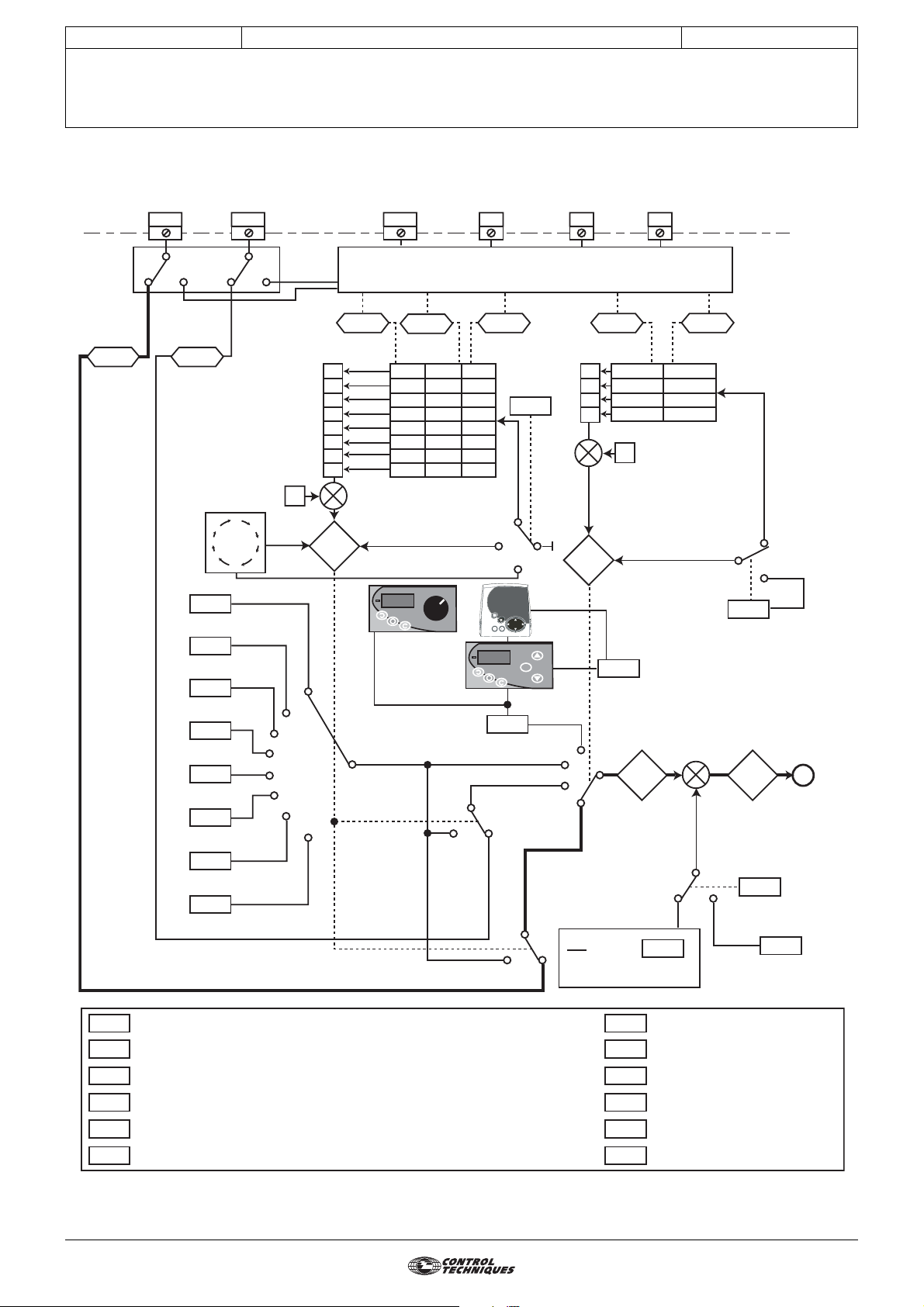
3.2 - Menu 1 diagram
3.2.1 - Selection of reference (speed)
ADI1 ADI2 DIO1 DI2 DI3 DI4
ADVANCED USER GUIDE
3854 en - 03.2008 / b
Menu 7
Analog
reference
1
1.36 1.37
Paramétrage cycleur
1.16
1.48
1.69
1.70
1.71
1.72
Analog
reference
2
Scan timer
7
Pr1
1.21
Pr2
1.22
Pr3
1.23
Pr4
1.24
Pr5
1.25
Pr6
1.26
Pr7
1.27
Pr8
1.28
Preset reference selector timer
Reference timer reset flag
Number of scanned references
Scan time selection
Preset 1 scan timer time
Preset 2 scan timer time
1
8 6 2
5
3
4
3
4
5
6
Preset
reference
select
1
1
2
7
8
+
0
1
2
3
4
5
6
7
1.50
1.47
Preset
reference
selected
indicator
1.46
0
0
0
0
1
0
1
0
0
1
0
1
1
1
1
1
1 to 8
Keypad control
mode reference
>1 and
1.15 = 0
>1 and
1.15 = 0
Menu 8
1.45 1.42 1.41
0
1
0
1
0
1
0
1
Preset
selector
0
9
1.17
1
1.15
M
0
1
2
3
1.49
4
3
2
1
Percentage trim
Ref
100
1
0
0
1
1
+
1
Reference
selected indicator
Power-up
keypad
control
mode
reference
1.51
Pre-offset
reference
1.60 1.01
x (100 + )
1.73
1.74
1.75
1.76
1.77
1.78
0
1
0
1
+
+
0
1.38
Preset 3 scan timer time
Preset 4 scan timer time
Preset 5 scan timer time
Preset 6 scan timer time
Preset 7 scan timer time
Preset 8 scan timer time
Reference
select
1.14
Reference
selector
Frequency/speed
reference selected
Reference
offset select
1.09
1
Reference
offset
0
1 to 4
A
1.04
24
Page 25
CONTROL TECHNIQUES
MENU 1: SPEED REFERENCE: SELECTION, LIMITING AND FILTERS
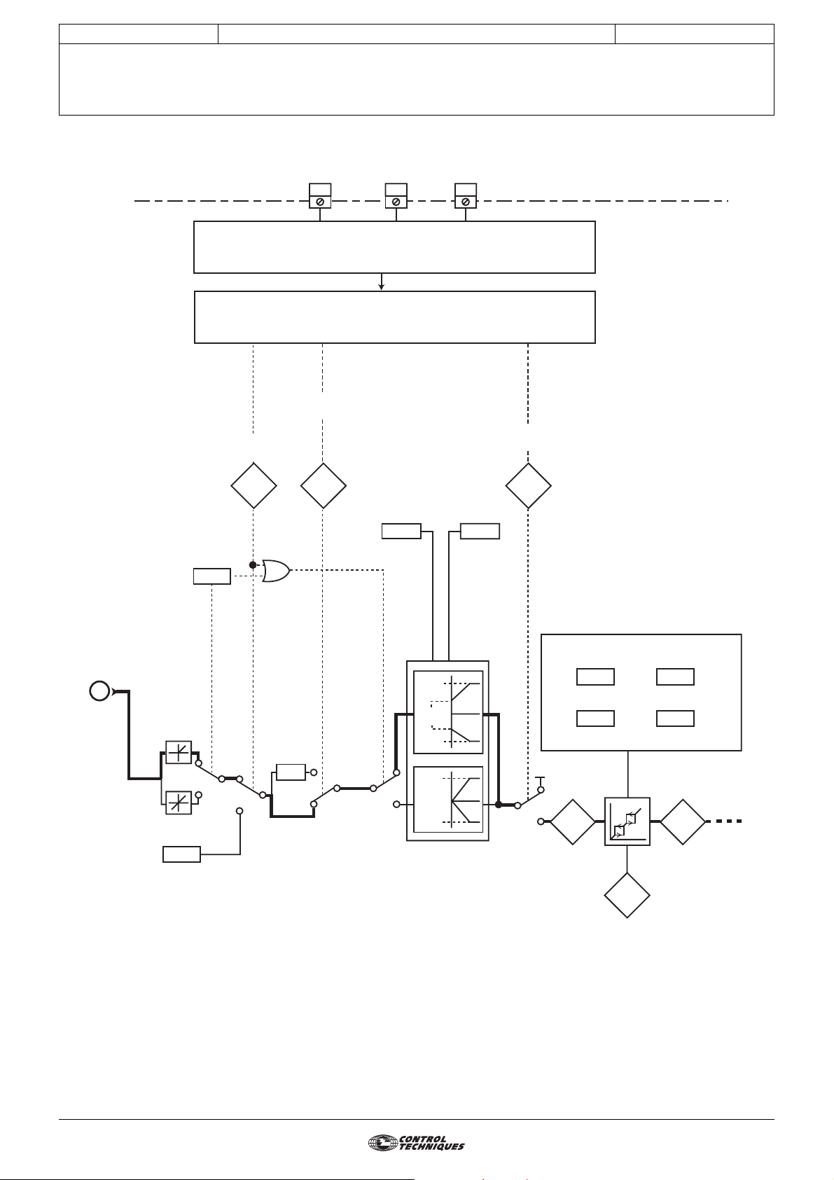
3.2.2 - Limiting and filters
Jog selected
indicator
ADVANCED USER GUIDE
Commander SX
IP66/Nema 4X variable speed drive
DI1DI2DI3
MENU 8
MENU 6
Reverse
selected indicator
Reference
enabled indicator
3854 en - 03.2008 / b
1.13 1.12 1.11
Bipolar
reference
enable
A
Jog reference
1.10
0
1
1.05
OU
0
1
X(-1)
1
0
Maximum
reference
clamp
1.06 1.07
0
1
reference
1.06
1.07
1.06
1.06
1.06
Minimum
clamp
Skip references
12
1.29
1.30
Pre-skip
filter
0
reference
1
1.02 1.03
Reference in
rejection zone
1.35
1.31
1.32
Pre-ramp
reference
Skip
Band
Menu 2
25
Page 26
CONTROL TECHNIQUES
MENU 1: SPEED REFERENCE: SELECTION, LIMITING AND FILTERS
ADVANCED USER GUIDE
Commander SX
IP66/Nema 4X variable speed drive
3854 en - 03.2008 / b
3.3 - Explanation of parameters in menu 1
1.01
Adjustment range :± 1.06
Indicates the reference value.
1.02
Adjustment range :± 1.06 or 1.07 to 1.06
Reference after limiting but before the skips.
1.03
Adjustment range :± 1.06 or 1.07 to 1.06
Indicates the reference after the skips but before the
acceleration or deceleration ramps.
1.04
Adjustment range :± 1.06
Factory setting :0
This reference is added to (positive value) or subtracted from
(negative value) the selected reference if 1.09 equals 1
(OFFS). It can be used to correct the selected main reference
to obtain an accurate setting.
1.05
Adjustment range :0 to 1.06 rpm
Factory setting :45 rpm
Operating speed when the jog input has been selected.
1.06
Adjustment range :0 to 32000 rpm
Factory setting :Eur = 1500 rpm
withstand it.
Maximum speed in both directions of rotation.
1.07
Adjustment range :0 to 1.06
Factory setting :0
In unipolar mode, defines the minimum speed.
WARNING:
• This parameter is inactive during jog operation.
• If the value of 1.06 is lower than that of 1.07, the value
of 1.07 is automatically changed to the new value of
1.06.
: Speed reference selected
: Pre-skip filter reference
: Pre-ramp reference
: Reference offset
: Jog reference
: Maximum reference clamp
USA = 1800 rpm
• Before setting the maximum reference clamp,
check that the motor and the driven machine can
: Minimum reference clamp
1.10
Adjustment range :0 or 1
Factory setting :0
0 (+ only ref) (PoS): All negative references are treated as
invalid.
1 (+ and - ref) (nEg): Used for changing the direction of
rotation by the reference polarity. May come from the preset
references.
Note: The drive analog inputs are unipolar.
1.11
Adjustment range :0 or 1
Used to control enabling of the run command.
0 (Disabled) (StoP): Stop.
1 (Enabled) (run): Run.
1.12
Adjustment range :0 or 1
Used to control enabling of the direction of rotation.
0 (Forward) (Fd): Forward.
1 (Reverse) (rS): Reverse.
1.13
Adjustment range :0 or 1
Used to control enabling of the jog command.
0 (Disabled) (OFF): Jog operation not enabled.
1 (Enabled) (Jog): Jog operation enabled.
1.14
Adjustment range :0 to 4
Factory setting :0
0 (Term. inputs) (SEL): The speed reference is selected by
combining the digital inputs assigned to parameters 1.41 and
1.42.
1 (Analog 1) (Ana1): The speed reference comes from
analog input 1.
2 (Analog 2) (Ana2): The speed reference comes from
analog input 2.
3 (Preset) (Pr): The speed reference comes from the preset
references.
4 (Keypad) (Pad): The speed reference comes from the
local control or the LCD keypad.
: Bipolar reference select
: Reference enable indicator
: Reverse select indicator
: Jog select indicator
: Reference selector
1.08
1.09
Adjustment range :0 or 1
Factory setting :0
0 (Ref x 01.38) (ProP): A value proportional to this
reference is added to the main reference. The percentage
is adjusted using the parameter 1.38.
1 (Ref + 01.04) (OFFS): A fixed value set in 1.04 is added
to the main reference.
26
: Not used
: Reference offset validation
Page 27
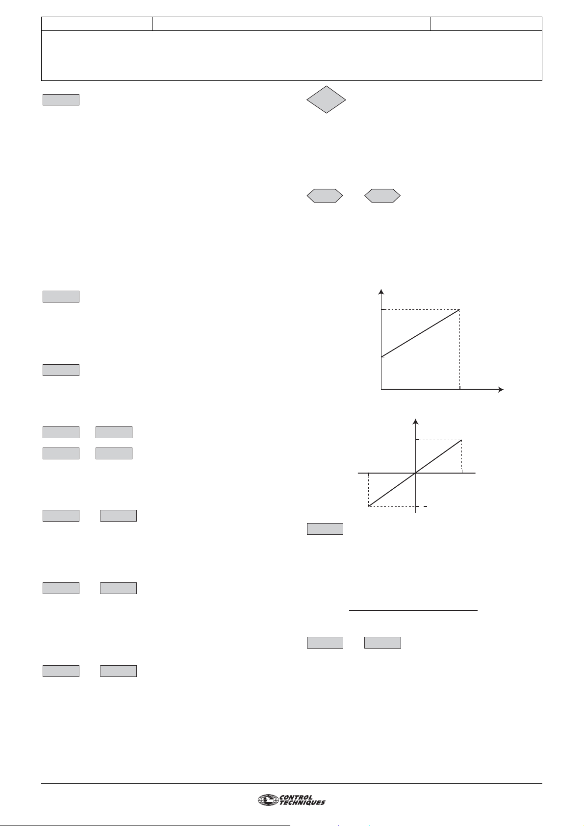
CONTROL TECHNIQUES
MENU 1: SPEED REFERENCE: SELECTION, LIMITING AND FILTERS
ADVANCED USER GUIDE
Commander SX
IP66/Nema 4X variable speed drive
3854 en - 03.2008 / b
1.15
Adjustment range :0 to 9
Factory setting :0
This parameter is used to select the preset references. It
works as follows:
0 (Term. inputs) (SEL): Is used to select the reference by
combining the digital inputs assigned to parameters
1.45 to 1.47.
1 (Preset 1) (Pr1): Preset reference 1
2 (Preset 2) (Pr2): Preset reference 2
3 (Preset 3) (Pr3): Preset reference 3
4 (Preset 4) (Pr4): Preset reference 4
5 (Preset 5) (Pr5): Preset reference 5
6 (Preset 6) (Pr6): Preset reference 6
7 (Preset 7) (Pr7): Preset reference 7
8 (Preset 8) (Pr8): Preset reference 8
9 (Timer) (Cycl): The reference is selected automatically by
a scan timer.
1.16
Adjustment range :0 to 9999 s
Factory setting :0
When 1.15 = 9 (timer), is used to set the time between each
reference where the scan time is identical between each
preset reference (1.70 is set to 0).
1.17
Adjustment range :1.07 to 1.06 (1.10 = 0)
Factory setting :0
Indicates the reference value coming from the local control or
the LCD console.
1.18 1.20
1.21 1.28
Adjustment range :± 1.06
Factory setting :0
In order, 1.21 to 1.28 are used to define preset references
Preset 1 to Preset 8.
1.29 1.31
Adjustment range :0 to 1.06 rpm
Factory setting :0
Two skips are available to avoid a machine running at critical
speeds. When one of these parameters is at 0, the function is
deactivated.
1.30 1.32
Adjustment range :0 to 300 rpm
Factory setting :15 rpm
Define the skip band around the avoided speed. The total skip
will therefore equal the threshold set ± skip band. When the
reference is within the window determined in this way, the
drive will not allow operation in this zone.
: Preset selector
: Preset reference selector timer
: Keypad reference
to : Not used
to : Preset references 1 to 8
and :Skip references 1 and 2
and :Skip reference bands 1 and 2
1.35
Adjustment range :0 or 1
0 (Out) (OFF): The selected reference is not within one of the
skip reference zones.
1 (In) (On): The selected reference is within one of the skip
reference zones. In this case, the motor speed does not
correspond to the requested reference.
1.36 1.37
Adjustment range :1.07 to 1.06 (1.10 = 0)
The analog inputs assigned to these parameters are
automatically scaled so that 100.0% of the input corresponds
to the maximum reference (1.06). Similarly the 0% input level
will correspond to the minimum reference 1.07 or 0
according to 1.10.
Unipolar mode (1.10 =0)
Bipolar mode (1.10 = 1), requires an Additional I/O option
1.38
Adjustment range :± 100.0%
Factory setting :0
An offset proportional to the selected reference can be added
to this reference.
The multiplication coefficient is determined by the analog
input assigned to 1.38.
Final ref =
1.39 1.40
: Reference in skip zone
and :Analog references 1 and 2
± 1.06 (1.10 = 1)
Reference
1.06
1.07
0
Reference
1.06
- 100.0
: Percentage trim
selected reference x (1.38 + 100)
100
and :Not used
100.0
+ 100.0
%
1.06
%
1.33 1.34
and :Not used
27
Page 28
CONTROL TECHNIQUES
MENU 1: SPEED REFERENCE: SELECTION, LIMITING AND FILTERS
ADVANCED USER GUIDE
Commander SX
IP66/Nema 4X variable speed drive
3854 en - 03.2008 / b
1.41 1.42
Adjustment range :0 or 1
0 (OFF)
1 (On)
Used to assign the digital inputs to selection of the speed
reference.
1.43 1.44
1.45 1.47
Adjustment range :0 or 1
0 (OFF)
1 (On)
Used to assign the digital inputs to selection of the preset
references.
1.45 1.46 1.47 Selected reference 1.50
0 0 0 Preset reference 1 (Preset 1) 1
1 0 0 Preset reference 2 (Preset 2) 2
0 1 0 Preset reference 3 (Preset 3) 3
1 1 0 Preset reference 4 (Preset 4) 4
0 0 1 Preset reference 5 (Preset 5) 5
1 0 1 Preset reference 6 (Preset 6) 6
0 1 1 Preset reference 7 (Preset 7) 7
1 1 1 Preset reference 8 (Preset 8) 8
1.48
Adjustment range :0 or 1
Factory setting :0
0 (OFF): Reset inactive.
1 (On): The preset reference scan timer is reset to zero. In
this case, the reference is once again Pr 1.
Can be used to control cycle starting via a digital input.
1.49
Adjustment range :0 to 4
0 (Term. inputs) (SEL):
1 (Analog 1) (Ana1): Analog input 1 reference is selected.
2 (Analog 2) (Ana2): Analog input 2 reference is selected.
3 (Preset) (Pr): The preset references are selected.
4 (Keypad) (Pad):
Indicates which reference has been selected.
and :Reference selector
1.41 1.42 Selected reference
0 0 Analog input 1
1 0 Analog input 2
0 1 Preset references
1 1 Reference via keypad
and :Not used
to : Preset reference selector
: Reference timer reset
: Selected refe r en ce indicator
1.50
Adjustment range :1 to 8
0 (Term. inputs) (SEL): Is used to select the reference by
combining the digital inputs assigned to parameters
1.45 to 1.47.
1 (Preset 1) (Pr1): Preset reference 1 selected.
2 (Preset 2) (Pr2): Preset reference 2 selected.
3 (Preset 3) (Pr3): Preset reference 3 selected.
4 (Preset 4) (Pr4): Preset reference 4 selected.
5 (Preset 5) (Pr5): Preset reference 5 selected.
6 (Preset 6) (Pr6): Preset reference 6 selected.
7 (Preset 7) (Pr7): Preset reference 7 selected.
8 (Preset 8) (Pr8): Preset reference 8 selected.
Indicates the selected preset reference.
1.51
Adjustment range :0 to 2
Factory setting :0
0 (Reset to 0) (rSet): On power-up, the keypad reference
is reset to zero.
1 (Last value) (Prec): On power-up, the keypad reference
retains the value it had before power-down.
2 (Preset 1) (Pr1): On power-up, the keypad reference takes
the value of preset reference 1 (1.21).
1.52 1.59
1.60
Adjustment range :± 1.06
Indicates the value of the selected reference before offset.
1.61 1.68
1.69
Adjustment range :1 to 8
Factory setting :8
Used to configure the number of preset references integrated
in the scan timer.
For example, if 1.69 = 3, the scan timer will perform a cycle
Pr 1 --> Pr 2 --> Pr 3 --> Pr 1 etc.
1.70
Adjustment range :0 or 1
Factory setting :0
0 (Same) (Iden): The time between each preset reference
is the same for all references.
1 (Different) (diFF): The time between each preset reference
is different.
: Selected preset reference indicator
: Power-up keypad reference
to : Not used
: Pre-offset reference
to : Not used
: Number of preset references timed
: Scan time selection
28
1.71
Adjustment range :0 to 9999 s
Factory setting :0
If 1.70 is set to 1, determines the time during which the drive
remains at reference Pr. 1.
1.72
Adjustment range :0 to 9999 s
Factory setting :0
If 1.70 is set to 1, determines the time during which the drive
remains at reference Pr. 2.
: Preset 1 scan timer time
: Preset 2 scan timer time
Page 29

CONTROL TECHNIQUES
MENU 1: SPEED REFERENCE: SELECTION, LIMITING AND FILTERS
ADVANCED USER GUIDE
Commander SX
IP66/Nema 4X variable speed drive
3854 en - 03.2008 / b
1.73
Adjustment range :0 to 9999 s
Factory setting :0
If 1.70 is set to 1, determines the time during which the drive
remains at reference Pr. 3.
1.74
Adjustment range :0 to 9999 s
Factory setting :0
If 1.70 is set to 1, determines the time during which the drive
remains at reference Pr. 4.
1.75
Adjustment range :0 to 9999 s
Factory setting :0
If 1.70 is set to 1, determines the time during which the drive
remains at reference Pr. 5.
1.76
Adjustment range :0 to 9999 s
Factory setting :0
If 1.70 is set to 1, determines the time during which the drive
remains at reference Pr. 6.
1.77
Adjustment range :0 to 9999 s
Factory setting :0
If 1.70 is set to 1, determines the time during which the drive
remains at reference Pr. 7.
: Preset 3 scan timer time
: Preset 4 scan timer time
: Preset 5 scan timer time
: Preset 6 scan timer time
: Preset 7 scan timer time
1.78
Adjustment range :0 to 9999 s
Factory setting :0
If 1.70 is set to 1, determines the time during which the drive
remains at reference Pr. 8.
: Preset 8 scan timer time
29
Page 30

CONTROL TECHNIQUES
MENU 1: SPEED REFERENCE: SELECTION, LIMITING AND FILTERS
ADVANCED USER GUIDE
Commander SX
IP66/Nema 4X variable speed drive
Notes
3854 en - 03.2008 / b
30
Page 31

CONTROL TECHNIQUES
ADVANCED USER GUIDE
Commander SX
IP66/Nema 4X variable speed drive
4 - MENU 2: RAMPS
4.1 - List of parameters in Menu 2
3854 en - 03.2008 / b
MENU 2: RAMPS
Parameter Name Type Adjustment range Factory setting
If 1.10 = 0 and 2.02 = 0:
0 to 1.06
2.01 Post-ramp reference RO/P
2.02
2.03 Ramp hold R-W 0 or 1 0
2.04 Deceleration ramp mode select R-W 0 to 3 1
2.05 Not used
2.06 S ramp enable R-W 0 or 1 0
2.07 S ramp acceleration limit R-W
2.08 Standard ramp voltage R-W T = 0 to 800 V
2.09 Not used
2.10 Acceleration rate selector R-W 0 to 9 1
2.11 Acceleration rate 1
to
2.18 Acceleration rate 8
2.19 Jog acceleration rate R - W
2.20 Deceleration rate selector R-W 0 to 9 1
2.21 Deceleration rate 1
to
2.28 Deceleration rate 8
2.29 Jog deceleration rate R-W
2.30
to
2.50
2.51 Ramp hold condition R-W 0 or 1 0
Ramp bypass ( )
to
to
Not used
If 1.10 = 0 and 2.02 = 1:
1.07 to 1.06
If 1.10 = 1: ±
R-W 0 or 1 0
R-W
0.1 to 600.0 s/1000 rpm 3.0 s/1000 rpm
0.1 to 600.0 s/1000 rpm 0.2 s/1000 rpm
R-W
0.1 to 600.0 s/1000 rpm 5.0 s/1000 rpm
0.1 to 600.0 s/1000 rpm 0.2 s/1000 rpm
1.06
2 to 10 10
--
Eur: 690V
USA: 750V
User
setting
31
Page 32

CONTROL TECHNIQUES
4.2 - Menu 2 diagrams
4.2.1 - Acceleration ramps
ADVANCED USER GUIDE
Commander SX
IP66/Nema 4X variable speed drive
MENU 2: RAMPS
digital inputs (Menu 9)
Menu 1
1.50
1 to 8
9
0
Acceleration
2.10
rate selector
3854 en - 03.2008 / b
Selection via
9.32
Acceleration rate 1
Acceleration rate 2
Acceleration rate 3
Acceleration rate 4
Acceleration rate 5
Acceleration rate 6
Acceleration rate 7
Acceleration rate 8
Pre-ramp
reference
Menu 1
1.03
2.11
2.12
2.13
2.14
2.15
2.16
2.17
2.18
1
2
3
4
5
6
7
8
acceleration
N
Jog
acceleration
rate
2.19
REV
t
1
FWD
acceleration
N
t
0
Jog selected
indicator
1.13
Menu 1
A
B
S ramp
acceleration
limit
2.07
0
1
2.06
S ramp
enable
C
32
Page 33

CONTROL TECHNIQUES
4.2.2 - Deceleration ramps
Selection via
digital inputs (Menu 9)
9.32
ADVANCED USER GUIDE
Commander SX
IP66/Nema 4X variable speed drive
MENU 2: RAMPS
1 to 8
9
1.50
Menu 1
2.21
2.22
Deceleration
rate selector
0
2.20
3854 en - 03.2008 / b
Deceleration rate 1
Deceleration rate 2
deceleration
A
B
2.04
2.08
Jog
rate
2.29
1
deceleration
N
Ramp mode select
Standard ramp voltage
0
FWD
t
REV
deceleration
N
1
2
3
4
5
6
7
8
Menu 4
t
1
0
Current
controller
Ramp hold
2.03
Ramp hold
condition
2.51
Deceleration rate 3
2.23
2.24
Deceleration rate 4
2.25
Deceleration rate 5
Deceleration rate 6
2.26
Deceleration rate 7
2.27
2.28
Deceleration rate 8
0
Post-ramp
reference
2.01
1
Menu 3
Ramp by-pass
( )
2.02
1
0
V min
00
C
33
Page 34

CONTROL TECHNIQUES
ADVANCED USER GUIDE
Commander SX
IP66/Nema 4X variable speed drive
MENU 2: RAMPS
3854 en - 03.2008 / b
4.3 - Explanation of parameters in menu 2
2.01
Adjustment range :• If 1.10 = 0 and 2.02 = 0: 0 to 1.06
Measurement of the post-ramp reference. Used for
diagnostics.
2.02
Adjustment range :0 or 1
Factory setting :0
0 (Off) (no): Active ramps.
1 (On) (raMP): Ramps short-circuited.
2.03
Adjustment range :0 or 1
Factory setting :0
0 (Off) (raMP): Ramp freed.
1 (On) (StoP): The ramp is held and acceleration (or
deceleration) is therefore interrupted.
WARNING:
The ramp hold function is disabled if a stop command is
given.
2.04
Adjustment range :0 to 3
Factory setting :1
0 (Fast) (Fst): Deceleration ramp imposed. If the deceleration
ramp that has been configured is too fast in relation to the
inertia of the load, the DC bus voltage exceeds its maximum
value (set in 2.08) and the drive trips on "OU" overvoltage.
WARNING:
Select mode 2.04 = 0 (Fst) when a braking resistor is
used.
1 (Standard) (Std): Standard deceleration ramp with
automatic extension of the ramp time in order to avoid
causing a DC bus overvoltage trip on the drive (threshold
set in 2.08).
2 (Standard+) (StdH): The drive allows the motor voltage to
be increased up to 1.2 times the rated voltage set in 5.09
(motor rated voltage), to avoid reaching the maximum DC bus
voltage threshold (threshold set in 2.08). However, if this is
not sufficient, the standard deceleration ramp time is
extended, to avoid causing a DC bus overvoltage trip on the
drive.
For the same amount of energy, mode 2 enables faster
deceleration than mode 1.
3 (Fast+) (FstH): Same as mode 2, but the ramp is imposed.
If the configured ramp is too fast, the drive goes into OU trip
state.
WARNING:
In mode 2 and 3, the motor must be capable of tolerating
additional losses relating to the increase in voltage at its
terminals.
: Post-ramp reference
• If 1.10 = 0 and 2.02 = 1: 1.07 to 1.06
• If 1.10 = 1: ± 1.06
: Ramp bypass ( )
: Ramp hold
: Deceleration ramp mode select
2.06
Adjustment range :0 or 1
Factory setting :0
0 (Off) (Lin): The ramp is linear.
1 (On) (S-rP): A curved part (defined in 2.07) at the start and
end of the ramp avoids load swinging (S ramp).
WARNING:
The S ramp is deactivated during controlled
decelerations (2.04 = 1 or 2).
2.07
Adjustment range :2 to 10
Factory setting :10
Used to modify the ramp curve by the same value at the start
and end of the ramp.
The value 4 represents a time for the curved part of 25% of
the total ramp and 10 represents a time for the curved part of
10%.
2.08
Adjustment range :0 to 800 V
Factory setting :Eur: 690 V, USA: 750 V
This threshold is used when the drive is configured in
standard deceleration mode (2.04 = 1 or 2).
If this threshold is too low, the machine will stop in freewheel
mode. If this threshold is too high and there are no resistors
connected, the drive will trip due to DC bus overvoltage ("OU"
trip).
The minimum value of this parameter must be 50 V higher
than the DC bus voltage obtained with the maximum supply
voltage (U bus = U supply x √2).
2.09
2.10
Adjustment range :0 to 9
Factory setting :1
This parameter is used to select the acceleration ramp as
follows:
0 (Term. inputs) (SEL): Selection of the acceleration ramp
via digital input. The choice of ramp comes from the bin ary
sum in menu 9 (9.32).
1 (Acceler.1) (Acc1): Acceleration ramp 1
2 (Acceler.2) (Acc2): Acceleration ramp 2
3 (Acceler.3) (Acc3): Acceleration ramp 3
4 (Acceler.4) (Acc4): Acceleration ramp 4
5 (Acceler.5) (Acc5): Acceleration ramp 5
6 (Acceler.6) (Acc6): Acceleration ramp 6
7 (Acceler.7) (Acc7): Acceleration ramp 7
8 (Acceler.8) (Acc8): Acceleration ramp 8
9 (To preset) (rP.Pr): The ramp is automatically associated
with the corresponding preset speed.
:S ramp enable
: S ramp acceleration limit
: Standard ramp voltage
: Not used
: Acceleration rate selector
34
2.05
: Not used
Page 35

CONTROL TECHNIQUES
ADVANCED USER GUIDE
Commander SX
IP66/Nema 4X variable speed drive
MENU 2: RAMPS
3854 en - 03.2008 / b
2.11 2.18
to : Acceleration rates 1 to 8
Adjustment range :0.1 to 600.0 s/1000 rpm
Factory setting :3 s/1000 rpm
Sets the time for acceleration from 0 to 1000 rpm.
2.11 to 2.18 =
t(s) x 1000 rpm
(N2 - N1) rpm
N (rpm)
1000
N2
N1
0
Value of 2.11 to 2.18
t
t (s)
2.11: Acceleration rate 1 (main ramp in factory settings)
2.12: Acceleration rate 2
2.13: Acceleration rate 3
2.14: Acceleration rate 4
2.15: Acceleration rate 5
2.16: Acceleration rate 6
2.17: Acceleration rate 7
2.18: Acceleration rate 8
2.19
: Jog acceleration rate
Adjustment range :0.1 to 600.0 s/1000 rpm
Factory setting :0.2 s/1000 rpm
Sets the time for acceleration from 0 to 1000 rpm.
2.19 =
t(s) x 1000 rpm
(N2 - N1) rpm
N (rpm)
1000
2.21 2.28
to : Deceleration rates 1 to 8
Adjustment range :0.1 to 600.0 s/1000 rpm
Factory setting :5.0 s/1000 rpm
Sets the time for deceleration from 1000 rpm to 0.
2.21 to 2.28 =
t(s) x 1000 rpm
(N2 - N1) rpm
N (rpm)
1000
N2
N1
0
Value of 2.21 to 2.28
t
t (s)
2.21: Deceleration rate 1 (main ramp in factory settings)
2.22: Deceleration rate 2
2.23: Deceleration rate 3
2.24: Deceleration rate 4
2.25: Deceleration rate 5
2.26: Deceleration rate 6
2.27: Deceleration rate 7
2.28: Deceleration rate 8
2.29
: Jog deceleration rate
Adjustment range :0.1 to 600.0 s/1000 rpm
Factory setting :0.2 s/1000 rpm
Sets the time for deceleration from 1000 rpm to 0.
2.29 =
t(s) x 1000 rpm
(N2 - N1) rpm
N (rpm)
1000
N2
N1
t (s)
2.20
0
t
Value of 2.19
: Deceleration rate selector
Adjustment range :0 to 9
Factory setting :1
This parameter is used to select the deceleration ramp as
follows:
0 (Term. inputs) (SEL): Selection of the deceleration ramp
via digital input. The choice of ramp comes from the binary
sum in menu 9 (9.32).
1 (Deceler.1) (Dec1): Deceleration ramp 1
2 (Deceler.2) (Dec2): Deceleration ramp 2
3 (Deceler.3) (Dec3): Deceleration ramp 3
4 (Deceler.4) (Dec4): Deceleration ramp 4
5 (Deceler.5) (Dec5): Deceleration ramp 5
6 (Deceler.6) (Dec6): Deceleration ramp 6
7 (Deceler.7) (Dec7): Deceleration ramp 7
8 (Deceler.8) (Dec8): Deceleration ramp 8
9 (To preset) (rP.Pr): The ramp is automatically associated
with the corresponding preset speed.
N2
N1
0
t
Value of 2.29
t (s)
2.30 2.50
2.51
to : Not used
: Ramp hold condition
Adjustment range :0 or 1
Factory setting :0
0 (ALL) (ALL): When 2.03 = 1, the ramp is always held.
1 (> V MIN) (S.Min): When 2.03 = 1, the ramp is freed
between 0 and V min (1.07).
35
Page 36

CONTROL TECHNIQUES
ADVANCED USER GUIDE
Commander SX
IP66/Nema 4X variable speed drive
MENU 2: RAMPS
Notes
3854 en - 03.2008 / b
36
Page 37

CONTROL TECHNIQUES
ADVANCED USER GUIDE
3854 en - 03.2008 / b
Commander SX
IP66/Nema 4X variable speed drive
MENU 3: FREQUENCY THRESHOLDS - ENCODER OPTION
5 - MENU 3: FREQUENCY THRESHOLDS - ENCODER OPTION
5.1 - List of parameters in Menu 3
Parameter Name Type Adjustment range Factory setting
3.01 Final speed demand RO/P
3.02 Motor speed RO/P
3.03 Speed error RO/P
3.04 Speed control output RO/P ± 300.0% -
3.05 Zero speed threshold R-W
3.06 At speed lower limit R-W
3.07
to
3.09
3.10 Speed loop proportional gain (Kp1) R-W 0 to 32000 200
3.11 Speed loop integral gain (Ki1) R-W 0 to 32000 100
3.12 Speed loop differential gain (Kd1) R-W 0 to 32000 0
3.13 Speed loop proportional gain (Kp2) R-W 0 to 32000 200
3.14 Speed loop integral gain (Ki2) R-W 0 to 32000 100
3.15 Speed loop differential gain (Kd2) R-W 0 to 32000 0
3.16 Speed gain select R-W 0 or 1 0
3.17 Speed gain setup R-W 0 to 2 0
3.18 Total inertia R-W
3.19 Not used
3.20 Bandwidth R-W 0.1 to 255.0 Hz 10.0 Hz
3.21 Damping factor R-W 0 to 10.0 1.0
3.22 Hard speed reference R-W
3.23 Hard speed reference selector R-W 0 or 1 0
3.24 Not used
3.25 Encoder phase angle R-W 0 to 359.9° 0
3.26
to
3.28
3.29 Drive encoder position RO/P -32768 to +32767 -
3.30
to
3.33
3.34 Encoder lines per revolution R-W 0 to 32000 lpr 1024 lpr
3.35
to
3.37
3.38 Encoder type R-W 0 to 8
3.39
to
3.41
3.42 Drive encoder filter R-W 0 to 10 3.0
3.43 Maximum frequency input encoder reference R-W 0 to 32000 5000
3.44 Frequency input reference scale R-W 0 to 2.0000 1.0000
3.45 Frequency input reference
3.46 Frequency input reference destination R-W/P 0.00 to 21.51 0.00
Not used
Not used
Not used
Not used
Not used
RO/P 0 to 100% RO/P ± 100% -
± 2 x 1.06 rpm
± 2 x 1.06 rpm
± 2 x 1.06 rpm
0 to 500 rpm 3 0 rpm
0 to 500 rpm 3 0 rpm
0.001 to 32.000 Kkgm
0 to 2 x 1.06 rpm
2
If 11.31 = 0 to 2:
-
0.001 Kkgm
0
0
If 11.31 = 3: 3
User
setting
-
-
-
2
-
-
-
: Function not available
37
Page 38

CONTROL TECHNIQUES
ADVANCED USER GUIDE
Commander SX
IP66/Nema 4X variable speed drive
MENU 3: FREQUENCY THRESHOLDS - ENCODER OPTION
3854 en - 03.2008 / b
Parameter Name Type Adjustment range Factory setting
3.47
to
3.50
3.51 Vmin alarm threshold R-W
3.52 V max alarm threshold R-W
3.53
to
3.60
3.61 Frequency input source R-W/P 0.00 to 21.51 0.00
3.62 Input frequency RO/P 0 to 5000 Hz -
3.63 Maximum frequency output reference R-W 0 to 1000.0 Hz 20.0 Hz
3.64 Frequency output reference scale R-W 0 to 32.00 1.00
3.65 Frequency output reference RO/P 0 to 100% -
3.66 Not used
3.67 Frequency input select R-W 0 or 1 0
3.68 Minimum frequency threshold R-W 1.0 to 10.0 Hz 1.0 Hz
3.69
and
3.70
3.71 Frequency output reference source R-W/P 0.00 to 21.51 0.00
3.72 Frequency output period RO/P 0.001 to 2.000 s -
3.73 Frequency output signal RO/P 0 or 1 -
Not used
0 to 500 rpm 90 rpm
0 to 500 rpm 90 rpm
Not used
Not used
User
setting
-
-
-
-
38
Page 39

CONTROL TECHNIQUES
ADVANCED USER GUIDE
Commander SX
IP66/Nema 4X variable speed drive
MENU 3: FREQUENCY THRESHOLDS - ENCODER OPTION
Notes
3854 en - 03.2008 / b
39
Page 40

CONTROL TECHNIQUES
MENU 3: FREQUENCY THRESHOLDS - ENCODER OPTION
5.2 - Menu 3 diagram
5.2.1 - Basic version
ADVANCED USER GUIDE
Commander SX
IP66/Nema 4X variable speed drive
Motor
3854 en - 03.2008 / b
Menu 2 Menu 5
Motor
rpm
5.04
Motor
control
Minimum
frequency
clamp
1.07
Maximum
frequency
clamp
1.06
5.01
Zero speed
threshold
3.05
Minimum
frequency clamp
1.07
Vmin alarm
threshold
+
3.51
Vmax alarm
threshold
-
3.52
Maximum frequency
clamp
1.06
M
Zero
speed
+
-
+
-
+
-
+
-
+
-
10.03
Vmin
alarm
10.51
Maximum
speed
10.53
Menu 10
Running at
or below min speed
10.04
Vmax
alarm
10.52
Reference
1.03
Reference
1.03
lower limit
-
lower limit
+
At speed
3.06
2
At speed
3.06
2
Below set
speed
+
-
-
+
10.05
Above set
speed
10.07
At
speed
10.06
40
Page 41

CONTROL TECHNIQUES
MENU 3: FREQUENCY THRESHOLDS - ENCODER OPTION
Basic version (continued)
Frequency input
Frequency
input
source
3.61
Frequency
conversion
Frequency output
Frequency
output reference
source
3.71
ADVANCED USER GUIDE
Commander SX
IP66/Nema 4X variable speed drive
Maximum frequency
input encoder reference
3.43
Frequency
input
reference
3.45
3.72 3.73
Frequency
conversion
Min.
3.68
frequency
threshold
Frequency
output
reference
scale
3.64
Frequency
output
reference
3.65
Input
frequency
3.62
Maximum frequency
output reference
100 %
100 %
0
3.63
0
Frequency
output
period
3854 en - 03.2008 / b
Frequency input
reference destination
Frequency
input
reference
scale
3.44
3.46
Frequency
output
signal
41
Page 42

CONTROL TECHNIQUES
IP66/Nema 4X variable speed drive
MENU 3: FREQUENCY THRESHOLDS - ENCODER OPTION
5.2.2 - With encoder option
Encoder feedback option
Final speed
reference
+-
Hard speed
reference
1
3.22
Encoder phase angle
0
Drive
encoder type
3.38
Drive encoder
lines per revolution
3.34
3.25
Drive encoder filter
3.42
Menu 2
Hard
speed
reference
Encoder
Post-ramp
reference
2.01 3.01 3.03 3.04
selector
3.23
Speed
feedback
ADVANCED USER GUIDE
Commander SX
Speed
error
3.12
D
3.02
Speed controller gains
reference clamp
Maximum
reference
clamp
Maximum
reference
clamp
+
-
3.10
P
3.11
I
Zero speed
threshold
3.05
Minimum
1.07
Vmin alarm
threshold
3.511.07
Vmax
alarm
threshold
3.521.06
Maximum
reference
clamp
1.06
3854 en - 03.2008 / b
Speed
controller output
Menu 10
+
-
+
-
+
-
+
-
Maximum
+
-
Running at
or below
min speed
10.04
Vmin
alarm
10.51
Vmax
alarm
10.52
speed
10.53
Zero
speed
10.03
Drive encoder
position
3.29
Reference
1.03
Reference
1.03
At speed
lower limit
-
At speed
lower limit
+
3.06
2
3.06
2
Below
set speed
+
-
-
+
10.05
Above
set speed
10.07
At
speed
10.06
42
Page 43

CONTROL TECHNIQUES
IP66/Nema 4X variable speed drive
MENU 3: FREQUENCY THRESHOLDS - ENCODER OPTION
With encoder option (continued)
Frequency input
Frequency
input source
3.61
Frequency
conversion
Min.
3.68
frequency
threshold
Frequency output
Frequency output
reference source
3.71
Frequency
output
reference
scale
3.64
ADVANCED USER GUIDE
3854 en - 03.2008 / b
Commander SX
Motor speed
Input
from
encoder
Frequency
output
reference
3.65 3.72 3.73
3.02
Input
frequency
3.62
Maximum frequency
output reference
100 %
0
+100 %
Maximum
frequency
input encoder
reference
100 %
0
3.63
-100 %
3.43
Frequency
input select
Frequency
output
period
1
0
3.67
Frequency
input
reference
3.45
Frequency
conversion
Frequency input
reference destination
3.46
Frequency
input
reference
scale
3.44
Frequency
output
signal
43
Page 44

CONTROL TECHNIQUES
ADVANCED USER GUIDE
Commander SX
IP66/Nema 4X variable speed drive
MENU 3: FREQUENCY THRESHOLDS - ENCODER OPTION
3854 en - 03.2008 / b
5.3 - Explanation of parameters in menu 3
Parameters marked with the symbol can only be
accessed when an encoder feedback option is present.
3.01
Adjustment range :± 2 x 1.06 rpm
Represents the sum of the post ramp reference and the hard
speed reference if this has been enabled.
3.02
Adjustment range :± 2 x 1.06 rpm
Actual speed from the encoder.
3.03
Adjustment range :± 2 x 1.06 rpm
Difference between the final speed reference and the speed
feedback.
3.04
Adjustment range :± 300.0%
The speed control output produces a torque reference to be
used in determining the value of the active current.
3.05
Adjustment range :0 to 500 rpm
Factory setting :30 rpm
If the motor speed 2.01 is at or below the level defined by this
parameter, the zero speed alarm 10.03 will be at 1,
otherwise it will be at 0.
3.06
Adjustment range :0 to 500 rpm
Factory setting :30 rpm
Defines the window within which the "At speed" alarm is
activated.
10.06 is at 1 when the post-ramp reference equals the
reference ± (3.06/2).
3.07 3.09
3.10
Adjustment range :0 to 32000
Factory setting :200
Adjusts the stability of the motor speed in the event of sudden
variations in the reference.
Increase the proportional gain until vibration occurs in the
motor, then reduce the value by 20 to 30%, checking that the
motor remains stable in the event of sudden variations in
speed, both at no load and on load.
3.11
Adjustment range :0 to 32000
Factory setting :100
Adjusts the stability of the motor speed on load impact.
Increase the integral gain so that the same speed is obtained
on load and at no load in the event of load impact.
WARNING: Do not configure a zero value in this
parameter (may cause difficulties when the motor stops).
: Final speed demand ( )
: Motor speed
: Speed error ( )
: Speed control output ( )
: Zero speed threshold
: At speed lower limit
to : Not used
: Speed loop proportional gain Kp1 ( )
: Speed loop integral gain Ki1 ( )
3.12
Adjustment range :0 to 32000
Factory setting :0
Adjusts the stability of the motor speed in the event of load
shedding or sudden variations in the reference.
Reduces overshoots.
In general, leave the setting at 0.
Function not available.
3.13
Adjustment range :0 to 32000
Factory setting :200
Adjusts the stability of the motor speed in the event of sudden
variations in the reference.
The drive uses Kp1 (3.10) or Kp2 (3.13) depending on the
value of 3.16.
3.14
Adjustment range :0 to 32000
Factory setting :100
Adjusts the stability of the motor speed on load impact.
The drive uses Ki1 (3.11) or Ki2 (3.14) depending on the
value of 3.16.
3.15
Adjustment range :0 to 32000
Factory setting :0
Adjusts the stability of the motor speed in the event of load
shedding or sudden variations in the reference.
The drive takes account of Kd1 (3.12) or Kd2 (3.15)
depending on the value of 3.16.
Function not available.
3.16
Adjustment range :0 or 1
Factory setting :0
This parameter can be modified when the drive is disabled or
enabled.
0 (Gain No1) (gai.1): Selection of gains Kp1 (3.10), Ki1
(3.11) and Kd1 (3.12).
1 (Gain No2) (gai.2): Selection of gains Kp2 (3.13), Ki2
(3.14) and Kd2 (3.15).
3.17
Adjustment range :0 to 2
Factory setting :0
0 (USER SETUP) (User): The speed loop operates with
the gains entered by the user.
1 (AUTO) (Auto): The speed loop operates with the gains
calculated from the total inertia entered in 3.18, the
bandwidth entered in 3.20 and the damping factor entered in
3.21.
2 (16 TIME) (Pr.16): For applications with very high inertia for
which a very high proportional gain is necessary, this mode
causes the proportional gain configured in 3.10 or 3.13 to be
multiplied by 16.
Function not available.
: Speed loop differential gain Kd1 ( )
: Speed loop proportional gain Kp2 ( )
: Speed loop integral gain Ki2 ( )
: Speed loop differential gain Kd2 ( )
: Speed gain select ( )
: Speed loop setup ( )
44
Page 45

CONTROL TECHNIQUES
ADVANCED USER GUIDE
Commander SX
IP66/Nema 4X variable speed drive
MENU 3: FREQUENCY THRESHOLDS - ENCODER OPTION
3854 en - 03.2008 / b
3.18
Adjustment range :0.001 to 32.000 Kkgm
Factory setting :0.001 Kkgm
Corresponds to the total inertia applied to the motor (motor
inertia + load inertia).
This parameter is used for automatic calculation of the gains
(see 3.17), and to provide a torque correction during
acceleration if necessary.
3.19
3.20
Adjustment range :0.1 to 255.0 Hz
Factory setting :10.0 Hz
Used to set the bandwidth taken into account with speed loop
operating mode 1 (see 3.17).
3.21
Adjustment range :0 to 10.0
Factory setting :1.0
Used to set the damping factor taken into account with speed
loop operating mode 1 (see 3.17).
3.22
Adjustment range :0 to 2 x 1.06 rpm
Factory setting :0
This hard speed reference is an additional reference which is
not affected by the ramps.
Function not available.
3.23
Adjustment range :0 or 1
Factory setting :0
0 (Off) (OFF): Hard speed reference selector inactive.
1 (On) (On): Used to add an unramped speed reference to
the main reference.
Function not available.
3.24
3.25
Adjustment range :0 to 359.9°
Factory setting :0
Indicates the result of the phasing test. It is stored when the
drive is powered down and will be modified automatically only
after a new phasing test.
the motor to rotate in the wrong direction or trip the drive.
3.26 3.28
3.29
: Total inertia ( )
2
: Not used
:Bandwidth ( )
: Damping factor ( )
: Hard speed reference ( )
: Hard speed reference selector
()
: Not used
: Encoder phase angle ( )
• The phase angle, where it is known, can be
entered manually. Any incorrect value can cause
to : Not used
: Drive encoder position ( )
2
3.34
Adjustment range :0 to 32000 lpr
Factory setting :1024 lpr
Used to configure the number of lines per encoder revolution.
Converts the encoder input into a speed.
3.35 3.37
3.38
Adjustment range :0 to 8
Factory setting :0 if 11.31 = 0 to 2
0 (INCREMENTAL) (Incr.) : Quadrature incremental
encoder
1 (Increm. FD) (Fd): Incremental encoder with Frequency/
Direction output
2 (Increm. FW/RV) (Fr): Incremental encoder with FWD/REV
outputs
3 (Increm. UVW) (CoMM): Incremental encoder with
commutation channels
4 (HALL EFFECT) (haLL): Hall effect sensor
5 (SENSORLESS 1) (tyP1): Sensorless mode 1
6 (SENSORLESS 2) (tyP2): Sensorless mode 2
7 (SENSORLESS 3) (tyP3): Sensorless mode 3
8 (SENSORLESS 4) (tyP4): Sensorless mode 4
3.39 3.41
3.42
Adjustment range :0 to 10
Factory setting :3.0
This parameter is used to insert a sliding window filter in the
encoder speed feedback, such that:
time constant = 2
This is particularly useful for attenuating the current demand
when the load has high inertia and high gain is necessary on
the speed loop. If the filter is not enabled under these
conditions, it is possible for the speed loop output to change
continuously from one current limit to another, disabling the
integral function of the speed loop.
The filter is inactive if 3.42 = 0.
3.43
Adjustment range :0 to 32000
Factory setting :5000
Adjusts the input frequency which should correspond to 100%
of the destination numerical value .
3.44
Adjustment range :0 to 2.0000
Factory setting :1.0000
Used for scaling the numerical reference to be converted into
pulses.
: Encoder lines per revolution
to : Not used
: Encoder type
3 if 11.31 = 3
to : Not used
: Drive encoder filter ( )
3.42
ms.
: Maximum frequency input encoder reference
: Frequency input reference scale
Adjustment range :-32768 to +32767
Indicates the position of the encoder in relation to the line it
was on at power-up.
3.30 3.33
to : Not used
3.45
Adjustment range :0 to 100% ( ); ± 100% ( )
Indicates the value of the numerical reference resulting from
conversion of the pulse signal.
: Frequency input reference
45
Page 46

CONTROL TECHNIQUES
ADVANCED USER GUIDE
Commander SX
IP66/Nema 4X variable speed drive
MENU 3: FREQUENCY THRESHOLDS - ENCODER OPTION
3854 en - 03.2008 / b
3.46
Adjustment range :0.00 to 21.51
Factory setting :0.00
Used to select the destination of the numerical reference
resulting from conversion of the pulse signal. Only "non-bit"
type parameters can be programmed. If an unsuitable
parameter is selected, 3.46 will be frozen at 0.
3.47 3.50
3.51
Adjustment range :0 to 500 rpm
Factory setting :90 rpm
Triggers an alarm 10.51 when the motor speed is such that:
- (5.04) < Vmin (1.07 or 21.02) + 3.51 in open loop mode,
- (3.02) < Vmin (1.07 or 21.02) + 3.51 in closed loop
mode.
3.52
Adjustment range :0 to 500 rpm
Factory setting :90 rpm
Triggers an alarm 10.52 when the motor speed is such that:
- (5.04) > Vmax (1.06 or 21.01) - 3.52 in open loop mode,
- (3.02) > Vmax (1.06 or 21.01) - 3.52 in closed loop
mode.
3.53 3.60
3.61
Adjustment range :0.00 to 21.51
Factory setting :0.00
Used to select the source of pulses. Only "bit" type
parameters can be programmed. If an unsuitable parameter
is selected, 3.61 will be frozen at 0.
Note: Only use inputs ADI1, ADI2, DIO1, DI2 and DI3 as the
frequency input source. The maximum input frequency
should be 5 kHz. If the input frequency is more than 5 kHz,
use an encoder feedback option, and set 3.67 to 1 (EnCd).
3.62
Adjustment range :0 to 5000 Hz
Drive encoder frequency which will be converted to a
numerical reference.
Application example:
Pulses from an inductive sensor connected on a digital input
are converted to a reference which is assigned to the speed
reference.
3.63
Adjustment range :0 to 1000.0 Hz
Factory setting :20.0 Hz
Adjusts the pulse frequency which should correspond to
100% of the original numerical reference.
Note: Set 3.63 above 0.5 Hz, since the drive output is
inactive below this value.
: Frequency input reference destination
to : Not used
: Vmin alarm threshold
: Vmax alarm threshold
to : Not used
: Frequency input source
: Input frequency
: Maximum frequency output reference
3.65
Adjustment range :0 to 100%
Indicates the value of the analog reference.
3.66
3.67
Adjustment range :0 or 1
Factory setting :0
0 (Digital in) (Freq): An analog reference is generated
from a frequency signal.
1 (Encoder) (Encd): The encoder signal is used to generate
an analog reference (e.g. speed reference).
3.68
Adjustment range :1.0 to 10.0 Hz
Factory setting :1.0 Hz
This parameter is used to define a minimum signal absence
detection time for the frequency input. Used to adapt
detection to the period of the signal.
This minimum time = 1/(3.68).
3.69 3.70
3.71
Adjustment range :0.00 to 21.51
Factory setting :0.00
Used to select the source of the numerical reference which
will be converted into pulses.
3.72
Adjustment range :0.001 to 2.000 s
Frequency output period resulting from conversion of the
numerical reference.
Application example:
A potentiometer connected to an analog input generates a
reference which is converted into pulses whose period is
proportional to the reference. The pulses are assigned to the
run command.
3.73
Adjustment range :0 or 1
0 (Off) (OFF)
1 (On) (On)
Used to assign the drive output to a digital output if necessary,
e.g. DIO1.
Note: There is no counting above 2 seconds.
: Frequency output reference
: Not used
: Frequency input select ( )
: Minimum frequency threshold
and :Not used
: Frequency output reference source
: Frequency output period
: Frequency output signal
3.64
Adjustment range :0 to 32.00
Factory setting :1.00
Used for scaling the reference from the drive encoder.
46
: Frequency output reference scale
Page 47

CONTROL TECHNIQUES
ADVANCED USER GUIDE
Commander SX
IP66/Nema 4X variable speed drive
MENU 4: CURRENT AND TORQUE CONTROL
6 - MENU 4: CURRENT AND TORQUE CONTROL
6.1 - List of parameters in Menu 4
3854 en - 03.2008 / b
Parameter Name Type Adjustment range Factory setting
4.01 Current magnitude RO/P
4.02 Active current RO/P ± max. drive current - -
4.03 Not used
4.04 Current demand RO/P
4.05
and
4.06
4.07 Symmetrical current limit R-W 0 to + 300.0% (% active In) 165.0%
4.08 Torque reference R-W ± 300.0% (% active In) 0
4.09
and
4.10
4.11 Torque mode selector R-W 0 or 1 0
4.12 Current demand filter R-W 0 to 10 ms 0
4.13 Current loop proportional gain R-W 0 to 999 20
4.14 Current loop integral gain R-W 0 to 250 40
4.15 Thermal time constant R-W 0 to 250 s 89 s
4.16 Thermal protection mode R-W 0 or 1 0
4.17 Reactive current RO/P ± 9999 - -
4.18 Overriding current limit RO/P 0 to + 300% (% active In) - -
4.19 Overload accumulator RO/P 0 to 100.0% - -
4.20 Percentage load RO/P
4.21 Selection of load display R-W 0 or 1 0
4.22
to
4.51
4.52 Max. speed in torque control mode R-W
Not used
Not used
Not used
0 to max. current
drive (A)
± active current limit
(% active In)
± active current limit
(% active In)
0 to 32000 rpm 1500 rpm
--
--
--
User
setting
47
Page 48

CONTROL TECHNIQUES
6.2 - Menu 4 diagram
6.2.1 - Basic version
Menu 1
Torque
reference
4.08
Torque current
conversion
ADVANCED USER GUIDE
Commander SX
IP66/Nema 4X variable speed drive
MENU 4: CURRENT AND TORQUE CONTROL
Torque
Pre-ramp
reference
1.03
Menu 2
Ramps
Drive output
Current
demand
4.04
-
is at
current limit
+
0
10.09
1
mode selector
4.11
Current
controller
gains
Max. speed
in torque
control mode
4.52
P
I
0
1 1
4.13
4.14
+ -
3854 en - 03.2008 / b
Post-ramp
reference
2.01
Menu 5
Motor
control
5.01
M
Motor
Menu 5
Output
frequency
Current
measure-
ment
5.01
Selection
of load
display
5.06
Current
magnitude
4.01
4.21
1
0
Active current
4.02
4.20
Rated
frequency
Thermal time
4.15
constant
Thermal
4.16
protection mode
Overload
alarm
Overload
accumulator
Motor protection
10.17
4.19
0
Overload
accumulator
Active current limit
4.07
Overriding
current
limit
4.18
48
Reactive current
4.17
Page 49

CONTROL TECHNIQUES
IP66/Nema 4X variable speed drive
6.2.2 - With encoder option
ADVANCED USER GUIDE
Commander SX
MENU 4: CURRENT AND TORQUE CONTROL
DC bus supervision
3854 en - 03.2008 / b
Speed controller
output
Me n u 1
3.04
Torque
reference
4.08
Max. speed
in torque
control mode
4.52
Torque mode
selector
4.11
0
1
Torque/Current
conversion
Overrinding
current limit
4.18
Motor rated
Me n u 5
current
Current
demand
4.04
Rated power
factor (cos ϕ)
5.10 5.07
Standard
ramp voltage
Current demand
filter
4.12
Current limit
calculation
2.08
Current
controller
gains
5.05
P
I
Motor
4.13
4.14
M
DC bus
voltage
Reactive I
internal
measure-
ment
Current
measure-
ment
Selection
of load
display
Reactive current
Current
magnitude
4.01
4.21
1
0
Active
current
4.02
4.17
4.20
Motor protection
4.15
4.16
Percentage
Thermal time
constant
Thermal
protection mode
Overload
alarm
load
10.17
4.19
Active
current
limit
4.07
Overload
accumulator
49
Page 50

CONTROL TECHNIQUES
ADVANCED USER GUIDE
Commander SX
IP66/Nema 4X variable speed drive
MENU 4: CURRENT AND TORQUE CONTROL
3854 en - 03.2008 / b
6.3 - Explanation of parameters in menu 4
4.01
Adjustment range :0 to max. drive current (A)
Reading of the rms current in each drive output phase.
This is the result of the vectorial sum of the reactive current
and the active current.
4.02
Adjustment range :± max. drive current
Reading of the active current delivered by the drive.
The active current gives a fairly precise image of the motor
torque between 10 Hz and 50 Hz.
A negative value indicates operation in generator mode with
driving load whereas a positive value indicates operation in
motor mode.
4.03
4.04
Adjustment range :± active current limit (% active In)
The current demand is the result of conversion of the torque
reference 4.08 corrected by the active current limit 4.07.
4.05 4.06
4.07
Adjustment range :0 to +300.0% (% active In)*
Factory setting :165.0%
Determines the active current limit that applies in both motor
and generator mode in both directions of rotation.
With frequency control (4.11 = 0), the output frequency will
automatically be adjusted in order to adhere to the current
limit.
The current limit is an active current limit whereas the
maximum current permitted by the drive is a total current.
The maximum value of 4.07 can therefore take the following
value:
Max. active I = %
Max. total I = 150% drive In
Active In = motor In x cos ϕ
Reactive current =
* : The maximum value of 4.07 depends on the value of
11.32, 5.07 and 5.10, such that:
- For an induction motor (11.31 = 0, 1 or 2)
- For a synchronous motor (11.31 = 3)
: Current magnitude
: Active current
: Not used
: Current demand
and :Not used
: Active current limit
Max. total I2Reactive I
---------------------------------------------------------
(11.32 x 2,22)
(5.07 x 5.10)
(11.32 x 2,22)
Active In
Motor In2Active In
–
5.07
–
2
100×
2
x 100
x 100
4.08
Adjustment range :± 300.0% (% active In)
Factory setting :0
Main torque reference when the drive is configured for torque
control.
Give a positive reference for the torque to be applied
clockwise and conversely, a negative reference for the torque
to be applied counter-clockwise.
4.09 4.10
4.11
Adjustment range :0 or 1
Factory setting :0
0 (Speed) (SPd): Speed control with current limiting by
parameter 4.07.
1 (Torque) (trq): Torque control. The speed reference is no
longer active and the torque reference can be given by analog
reference 2 (if it is programmed on the torque reference,
parameter 4.08). Th e output frequency is adjusted so that
the active current measured by the drive equals the
reference.
essential to make sure that parameter 1.06, which limits
the maximum speed, is set so as to ensure the safety of
equipment and personnel.
When racing occurs, the maximum speed reached is
1.06 + 30%.
4.12
Adjustment range :0 to 10 ms
Factory setting :0
This filter is used to introduce a time constant aimed at
reducing any noise generated by the speed loop, such that:
time constant = 2
4.13
4.14
Adjustment range :4.13 = 0 to 999, 4.14 = 0 to 250
Factory setting :4.13 = 20
Due to a certain number of internal drive factors, oscillations
may occur in the following cases:
- Frequency control with current limiting around the rated
frequency and on load impacts
- Torque control on machines with a low load and around the
rated speed
- On a mains supply break or on a controlled deceleration
ramp when control via the DC bus is requested.
To reduce these oscillations, we recommend that you first:
- increase the proportional gain 4.13
- then reduce the integral gain 4.14.
: Torque reference
and :Not used
: Torque mode selector
• With torque control (4.11 = 1), the machine races
if the resistive torque drops to zero. It is therefore
: Current demand filter ( )
4.12
ms.
: Current loop proportional gain
: Current loop integral gain
4.14 = 40
50
Page 51

CONTROL TECHNIQUES
ADVANCED USER GUIDE
Commander SX
IP66/Nema 4X variable speed drive
MENU 4: CURRENT AND TORQUE CONTROL
3854 en - 03.2008 / b
4.15
Adjustment range :0 to 250 s
Factory setting :89 s
This parameter is used to define the motor thermal protection.
If known, the thermal time constant of the motor should be
entered directly in 4.15. Otherwise it should be calculated as
a function of the maximum time for which the motor can
tolerate 150% I
4.15 =
Note: When 7.11 = 8 (ADI2 configured as a PTC input), it is
possible to deactivate the motor thermal protection (itAC
motor overload trip) by setting 4.15 = 0.
4.16
Adjustment range :0 or 1
Factory setting :0
0 (Trip) (deF): The drive will trip when the threshold
defined in parameter 4.15 is reached.
1 (Curr. limit) (Auto): The limiting current will automatically
be reduced below 100% I
parameter 4.15 is reached.
4.17
Adjustment range :± 9999
Reactive current reading.
: Thermal time constant
.
N
Maximum duration at 150 % I
Maximum duration at 150 % I
0.674
0.674
: Thermal protection mode
when the threshold defined in
N
: Reactive current
N
N
4.21
Adjustment range :0 or 1
Factory setting :0
This parameter is used to obtain an indication of the load or
the total current on the display.
4.21
0 As % Inom Ld
1 In Amps A Display of the total motor
4.22 4.51
4.52
Adjustment range :0 to 32000 rpm
Factory setting :1500 rpm
In torque control mode, this parameter is used to set the
speed at which the drive reverts to speed regulation, in o rder
to avoid reaching an excessive rotation speed. The
maximum speed taken into account corresponds to the
value of parameter 4.52 + 20%.
Note: Parameter 1.06 Maximum reference clamp is always
active.
: Selection of load display
LCD
display
to : Not used
: Max. speed in torque control mode
LED
display
Functions
Display of the drive load
level 4.20.
4.18
Adjustment range :0 to +300% (% max. active In)
Depending on the system operation, indicates the rms current
limit in real time.
4.19
Adjustment range :0 to 100.0%
The accumulator increases according to the formula
4.19 =
When 4.19 reaches 100%, the drive goes into "It Ac" trip
state or causes the limiting current to be reduced.
4.20
Adjustment range :± active current limit (% active In)
This parameter indica tes the d rive load level. A positive value
indicates operation in motor mode whereas a negative value
indicates operation in generator mode (driving load).
: Overriding current limit
: Overload accumulator
2
(1-e
-t/4.15
)
2
x 100 %
4.01
(5.07 x 1,05)
: Percentage load
51
Page 52

CONTROL TECHNIQUES
ADVANCED USER GUIDE
Commander SX
IP66/Nema 4X variable speed drive
MENU 4: CURRENT AND TORQUE CONTROL
Notes
3854 en - 03.2008 / b
52
Page 53

CONTROL TECHNIQUES
ADVANCED USER GUIDE
Commander SX
IP66/Nema 4X variable speed drive
MENU 5: MOTOR CONTROL
7 - MENU 5: MOTOR CONTROL
7.1 - List of parameters in Menu 5
3854 en - 03.2008 / b
Parameter Name Type Adjustment range Factory setting
5.01 Output frequency RO/P ± 400.0 Hz - -
5.02 Output voltage RO/P 0 to 5.09 Volts - -
5.03 Output power RO/P 0 to 200 kW - -
5.04 Motor speed RO/P ± 2 x 1.06 rpm - -
5.05 DC bus voltage RO/P
5.06 Motor rated frequency R-W 0 to 400.0 Hz
5.07 Motor rated current R-W 0 to drive rated current (A)
5.08 Motor rated speed R-W 0 to 9999 rpm
5.09 Motor rated voltage R-W 0 to 480V
5.10 Rated power factor (cos ϕ) R-W 0 to 1.00 0.85
5.11 Number of motor poles R-W 0 to 4 0
5.12 Autotune R-W 0 to 2 0
5.13 Dynamic V to F R-W 0 or 1 0
5.14 Open loop mode select R-W 0 to 5 3 then 1
5.15 Boost R-W 0 to 25.0% of 5.09 0
5.16 Not used
5.17 Stator resistance R-W 0 to 32.000 Ω 0
5.18 Maximum switching frequency R-W 0 to 5 1
5.19 High stability modulation R-W 0 or 1 0
5.20 Quasi square output R-W 0 or 1 0
5.21
and
5.22
5.23 Voltage offset R-W 0 to 25.5 Volts 0 -
5.24 Transient inductance R-W 0 to 3200.0 mH 0
5.25 Stator inductance (Ls) R-W 0 to 3200.0 mH 150.0 mH
5.26
to
5.31
5.32 Motor torque per amp (Kt) R-W
5.33 Motor volt per 1000 rpm (Ke) R-W 0 to 10000 V 98 V
5.34 Speed display unit R-W 0 to 2 1
5.35
5.36
to
5.50
5.51 q axis inductance R-W 0 to 999.9 mH 150.0 mH
5.52 Gearless optimisation R-W 0 or 1 0
5.53
to
5.57
Not used
Not used
Disable automatic adjustment of the switching
frequency
Not used
Not used
: Function not available
Voltage code 200 : 0 to 420V
Voltage code 400 : 0 to 860V
Eur: 50.0 Hz
USA: 60.0 Hz
Motor rated
current
corresponding to
the rating
Motor rated
speed
corresponding to
the rating
Eur L: 200V
USA L: 230V
Eur H: 400V
USA H: 460V
0.01 to 320.00 NmA
R-W 0 or 1 0
-1
1.00 NmA
--
-1
User
setting
53
Page 54

CONTROL TECHNIQUES
ADVANCED USER GUIDE
Commander SX
IP66/Nema 4X variable speed drive
MENU 5: MOTOR CONTROL
3854 en - 03.2008 / b
Parameter Name Type Adjustment range Factory setting
5.58 Enable boost on starting R-W 0 or 1 0
5.59 Not used
5.60 Low speed switching frequency R-W 0 to 5 0
5.61 Switching frequency change threshold R-W 0 to 400.0 Hz 0
User
setting
54
Page 55

CONTROL TECHNIQUES
7.2 - Menu 5 diagram
Menu 2
Post-ramp
reference
2.01
Slip
compensation
ADVANCED USER GUIDE
Commander SX
IP66/Nema 4X variable speed drive
MENU 5: MOTOR CONTROL
Voltage control
Output
frequency
5.01
Autotune
5.12
5.13
Dynamic V to F
5.14
Open loop mode select
5.15
Boost
5.58
Enable boost on starting
3854 en - 03.2008 / b
Motor
speed
5.04
Menu
4
Motor
parameter
select
11.45
0
Motor 1 Motor 2
5.06
5.07
5.08
5.09
5.10
5.11
5.17
5.23
Motor 1
inductance
5.24 21.14 21.15
Active
4.02
current
1
21.06
21.07
21.08
21.09
21.10
21.11
21.12
21.13
Motor 2
inductance
Motor 2
parameters
active
Rated
frequency
I nominal
Rated
speed
Rated
voltage
Power
factor
(cos ϕ)
Number of
motor poles
Stator
resistance
Voltage
offset
Modulation
Maximum
5.18
switching frequency
High
stability
5.19
modulation
Quasi
square
5.20
output
Disable
automatic
adjustment of
5.35
the switching
frequency
Low speed
5.60
switching
frequency
Switching
frequency
5.61
change
threshold
Output
voltage
DC bus
5.02 5.05
Menu 6
Start/stop logic select
Absorbed
power
V x I x V 3
voltage
Output
power
5.03
M
Gearless optimisation
5.52
55
Page 56

CONTROL TECHNIQUES
ADVANCED USER GUIDE
Commander SX
IP66/Nema 4X variable speed drive
MENU 5: MOTOR CONTROL
3854 en - 03.2008 / b
7.3 - Explanation of parameters in menu 5
5.01
Adjustment range :± 400.0 Hz
5.01 is the drive output frequency.
5.02
Adjustment range :0 to 5.09 Volts
This is the rms voltage at the drive output.
5.03
Adjustment range :0 to 200 kW
5.03 is the calculated motor active power.
5.03 = 4.01 x 5.02 x (cos ϕ x ).
If this parameter has been assigned to an analog output via
menu 7, 10 V corresponds to the maximum power
measurable by the drive (I max = 150% of drive rated current).
5.04
Adjustment range :± 2 x 1.06 rpm
The motor speed is calculated according to the formula:
5.04 (rpm) =
5.05
Adjustment range :Voltage code 200 = 0 to 420 V
Indicates the DC bus voltage measurement.
5.06
Adjustment range :0 to 400.0 Hz
Factory setting :Eur = 50.0 Hz
This is the point at which motor operation changes from
constant torque to constant power.
In standard operation, it is the frequency indicated on the
motor nameplate.
: Output frequency
: Output voltage
: Output power
3
------------ -kW
1000
: Motor speed
60 x 5.01
number of pairs of motor poles
: DC bus voltage
Voltage code 400 = 0 to 860 V
:Motor rated frequency
USA = 60.0 Hz
5.07
:Motor rated current
Adjustment range :0 to drive rated current (A)
Factory setting :Motor rated current corresponding
to the drive rating (see section 7.4)
This is the value of the motor rated current indicated on the
nameplate. The overload is calculated from this value.
5.08
:Motor rated speed
Adjustment range :0 to 9999 rpm
Factory setting :Motor rated speed corresponding
to the drive rating (see section 7.4)
This is the on-load speed of the motor indicated on the
nameplate.
5.09
:Motor rated voltage
Adjustment range :0 to 480V
Factory setting :Eur (voltage code 200) : 200 V,
USA (voltage code 200) : 230 V
Eur (voltage code 400) : 400 V,
USA (voltage code 400) : 460 V
Defines the voltage/frequency ratio as follows:
Output voltage
5.06
Output voltage
characteristic for
boost of less
than 6.25 %
Output
frequency
5.09
5.09
2
Boost
*
5.06
2
* If the fixed boost has been selected 5.14 = 2.
5.10
: Rated power factor (Cos ϕ)
Adjustment range :0 to 1.00
Factory setting :0.85
The power factor is measured automatically during a level 2
autotune phase (see 5.12) and set in this parameter. If it has
not been possible to carry out the autotune procedure, e nter
the Cos ϕ value indicated on the motor nameplate.
5.11
:Number of motor poles
Adjustment range :0 to 4
Factory setting :0
0 (Automatic) (Auto)
1 (2 Poles) (2P)
2 (4 Poles) (4P)
3 (6 Poles) (6P)
4 (8 Poles) (8P)
When this parameter is at 0, the drive automatically
calculates the number of poles according to the rated speed
(5.08) and the rated frequency (5.06). However, the value
can be entered directly in accordance with the table below:
Motor rated speed rpm
Number of poles 5.11
3000 2 1
1500 4 2
1000 6 3
750 8 4
56
Page 57

CONTROL TECHNIQUES
ADVANCED USER GUIDE
Commander SX
IP66/Nema 4X variable speed drive
MENU 5: MOTOR CONTROL
3854 en - 03.2008 / b
5.12
: Autotune
Adjustment range :0 to 2
Factory setting :0
• The measurement taken when 5.12 = 2 should be
taken with the motor uncoupled since the variable
speed drive drives the motor at 2/3 of its rated speed.
Check that this operation does not present any risk to
safety, and ensure that the motor is stopped before the
autotune procedure.
• After modifying the motor parameters, repeat
autotuning.
0 (Off) (no): No autotune
1 (Stationary) (StoP): Measurement of motor characteristics
when stopped.
The stator resistance and the voltage offset are stored in
5.17 and 5.23 respectively.
Procedure:
- Ensure that the motor parameters have been configured and
that the motor is stopped.
- Unlock the drive.
- Give a run command. The display indicates "Auto" and
"tunE" alternately. Wait for the display to stabilise at 0.
- Disable the drive and remove the run command.
The motor is then ready to operate normally.
Parameter 5.12 returns to 0 as soon as autotuning is
complete.
WARNING:
This autotuning is performed automatically even though
5.12 = 0, in the following cases:
- initial drive commissioning
- return to factory settings, after the drive has been
unlocked and a run command given
2 (Rotating) (rot): Measurement of motor characteristics
while rotating.
The stator resistance and the voltage offset are stored in
5.17 and 5.23 respectively, and the reactive current and
leakage inductance are used to calculate the power factor
5.10. This mode is used to obtain optimum performance.
Procedure:
- Ensure that the motor parameters have been configured and
that the motor is stopped.
- Unlock the drive.
- Give a run command. The motor accelerates up to 2/3 of
rated speed, then performs a freewheel stop. During
autotuning, the display indicates "Auto" and "tunE"
alternately. Wait for the display to stabilise at 0.
Disable the drive and remove the run command.
The motor is then ready to operate normally.
Parameter 5.12 returns to 0 as soon as autotuning is
complete.
5.13
: Dynamic V to F
Adjustment range :0 or 1
Factory setting :0
0 (Linear) (Lin): The V/F ratio is fixed and set by the base
frequency (5.06).
1 (Dynamic) (dyn): Dynamic V/F ratio.
Generates a voltage/frequency characteristic which varies
with the load. It is for use in quadratic torque applications
(pumps/fans/compressors). It can be used in constant torque
applications with low dynamics to reduce motor noise.
5.14
: Open loop mode select
Adjustment range :0 to 5
Factory setting :3
Determines the open loop control mode. Modes 0, 1, 3 or 4
are used in flux vector control . The difference between these
modes is the method used to identify the motor parameters,
particularly the stator resistance. As these parameters vary
with the temperature and are essential to obtain optimum
performance, the machine cycle should be taken into account
when selecting the most appropriate mode. Modes 2 and 5
correspond to a U/F ratio control mode. This ratio is linear in
mode 2 and square in mode 5.
0 (RS:EACH RUN) (r.run): The stator resistance and voltage
offset are measured each time the drive receives a run
command.
These measurements are only valid if the machine is
stopped, and totally defluxed. The measurement is not taken
when the run command is given less than 2 seconds after the
previous stop. This is the most effective flux vector control
mode. However, the operating cycle must be compatible with
the 2 seconds required between a stop command and a new
run command.
1 (RS:NO Mes.) (r.no): The stator resistance 5.17 and
voltage offset 5.23
are not measured.
This mode is of course the least effective. It should be used
only when mode 0 (r.run) is incompatible with the operating
cycle. If this were the case, during commissioning, an
autotune (5.12) should be performed to read the values
measured in 5.17 and 5.23 and these should be used with
mode 1 (r.no) in normal operation.
2 (LINEAR V/F) (UtoF): Voltage-frequency ratio with fixed
boost adjustable via parameters 5.15 and 5.09.
Motor voltage
5.09
5.09/2
Boost
5.15
5.06/2
5.06
Motor frequency
WARNING:
Use this mode to control several motors.
3 (RS:1st RUN) (r.FSt): operation equivalent to setting 1
(RS:NO Mes.) (r.no).
4 (RS:POWER UP) (r.On): operation equivalent to setting 0
(RS:EACH RUN) (r.run) after the first start.
5 (V/F SQUARE) (SqrE): Square law characteristic.
Motor voltage
5.09
Boost
5.15
5.06
Motor frequency
• In mode 4 (r.On), a voltage is briefly applied to the
motor. For safety, no electrical circuit must be
accessible once the drive has been powered up.
57
Page 58

CONTROL TECHNIQUES
ADVANCED USER GUIDE
Commander SX
IP66/Nema 4X variable speed drive
MENU 5: MOTOR CONTROL
3854 en - 03.2008 / b
5.15
:Boost
Adjustment range :0 to 25.0% of motor Un (5.09)
Factory setting :0
For operation in U/F mode (5.14 at 2) or in open loop flux
vector mode if 5.58 = 1, parameter 5.15 is used to overflux
the motor at low speed so that it delivers more torque on
starting. It is a percentage of the rated motor voltage (5.09).
Motor
voltage
5.09
5.09
2
Boost
)
(
5.15
5.06
Motor
frequency
5.16
5.17
5.06
2
: Not used
: Stator resistance
Adjustment range :0 to 32.000Ω
Factory setting :0
This parameter stores the motor stator resistance for flux
vector control mode (see parameter 5.14).
The stator resistance value is only read if 5.14 = 0.
If the stator resistance cannot be measured (motor not
connected, value higher than the max. rating) an "rS" trip
occurs.
During autotuning (5.12 = 1 or 2), the value of the stator
resistance is automatically stored in 5.17.
5.18
: Maximum switching frequency
Adjustment range :0 to 5
Factory setting :1
Sets the PWM switching frequency.
5.18 LCD display LED display
0 3 kHz 3hH
1 4.5 kHz 4.5hH
2 5.5 kHz 5.5hH
3 6 kHz 6hH
4 9 kHz 9hH
5 11 kHz 11hH
WARNING:
A high switching frequency reduces the magnetic noise,
but it increases the motor temperature rise and the level
of radio-frequency interference emission, and reduces
the starting torque.
If the temperature of the IGBTs becomes too high, the
drive can reduce the switching frequency selected by the
user (see 5.35 and 10.18).
5.19
: High stability modulation
Adjustment range :0 or 1
Factory setting :0
0 (Disabled) (OFF): Function disabled.
1 (Enabled) (On): Function enabled. Instabilities can occur:
- at 50% of the motor rated frequency for an underloaded
motor
- around and above the motor rated speed, when the motor is
underloaded or very heavily loaded.
This function is used to eliminate these instabilities.
It also enables a slight reduction in the drive temperature rise.
However, using this mode may result in a sli ght increase in
motor noise.
5.20
: Quasi square output
Adjustment range :0 or 1
Factory setting :0
0 (Disabled) (OFF): Function disabled.
1 (Enabled) (On): The maximum drive output voltage is
higher, resulting in an increase in motor torque. This is
beneficial for applications where it is desirable to reduce
speed pick-up times in the event of long cycles.
However, the motor torque may have slight ripples when it is
lightly loaded.
Function not available.
5.21 5.22
5.23
and :Not used
: Voltage offset
Adjustment range :0 to 25.5 volts
Factory setting :0
This voltage offset is measured by the drive (see parameter
5.14). It is used to correct imperfections in the drive,
especially voltage drops in the IGBTs and idle times. This
parameter plays an important role in low-speed operation, i.e.
when the drive output voltage is low.
During autotuning (5.12 = 1 or 2), the value of the voltage
offset is automatically stored in 5.23
5.24
: Transient inductance
.
Adjustment range :0 to 3200.0 mH
Factory setting :0
During autotuning with rotation (5.12 = 2), the transient
inductance is stored in this parameter.
5.25
: Stator inductance (Ls)
Adjustment range :0 to 3200.0 mH
Factory setting :150.0 mH
This is the motor stator inductance at rated flux.
5.26 5.31
5.32
Adjustment range :0.01 to 320.00 NmA
Factory setting :1.00 NmA
to : Not used
: Motor torque per amp (Kt)
-1
-1
Indicates the motor torque per Amp of active current used to
calculate the drive speed loop gains (3.17 = 1).
Function not available.
58
Page 59

CONTROL TECHNIQUES
ADVANCED USER GUIDE
Commander SX
IP66/Nema 4X variable speed drive
MENU 5: MOTOR CONTROL
3854 en - 03.2008 / b
5.33
Adjustment range :0 to 10000 V
Factory setting :98 V
Used to set the motor voltage per 1000 rpm. Is used to adjust
the current loop integral gain to prevent current peaks wh en
the drive is enabled with a spinning motor.
5.34
Adjustment range :0 to 2
Factory setting :1
5.34
0Hertz Fr
1
2 Customised Cd
5.35
Adjustment range :0 or 1
Factory setting :0
0 (Enabled) (Auto): In the event of increased temperature
of the IGBTs, the switching frequency is automatically
reduced.
1 (Disabled) (no): Automatic adjustment of the switching
frequency is disabled. In this case, the drive trips if the
temperature of the IGBTs is too high.
5.36 5.50
: Motor volt per 1000 rpm (Ke)
: Speed display unit
LCD
display
rpm
: Disable automatic adjustment of the
switching frequency
to : Not used
LED
display
SP
Function
Output frequency
expressed in Hz (5.01)
Motor speed expressed
in rpm (5.04)
Customer unit defined
using a coefficient
determined in parameter
11.21 as follows:
Cd = 5.04
motor speed in rpm
x 11.21
5.60
Adjustment range :0 to 5
Factory setting :0
Used to set a switching frequency different from that set in
5.18, when the motor frequency 5.01 has reached a
threshold defined in 5.61.
WARNING:
A high switching frequency reduces the magnetic noise,
but it increases the motor temperature rise and the level
of radio-frequency interference emission, and reduces
the starting torque.
5.61
Adjustment range :0.0 to 400.0 Hz
Factory setting :0.0 Hz
If the motor frequency 5.01 is below the threshold set by
5.61, the switching frequency selected by 5.60 is used.
Otherwise, it is the switching frequency set in 5.18 which is
active.
Reminder: F = (pp x S)/60
where F is the frequency in Hz, pp the number of poles and S
the speed in rpm.
: Low-speed switching frequency
5.60 LCD display LED display
02 kHz2 hH
1 2.5 kHz 2.5 hH
23 kHz3 hH
3 4.5 kHz 4.5 hH
4 5.5 kHz 5.5 hH
56 kHz6 hH
: Switching frequency change
threshold
5.51
Adjustment range :0 to 999.9 mH
Factory setting :150.0 mH
This is the motor stator inductance in quadrature with the total
inductance Ls (5.25), used to control a salient-pole
synchronous motor.
5.52
Adjustment range :0 or 1
Factory setting :0
0 (Disabled) (OFF): Optimisation deactivated.
1 (Enabled) (On): Optimisation activated. Used to obtain a
more regular rotation at very low speed (the torque is lower,
but "smoother").
5.53 5.57
5.58
Adjustment range :0 or 1
Factory setting :0
0 (Disabled) (OFF): No action.
1 (Enabled) (On): In open loop mode, voltage boost on
starting (5.15) is active.
5.59
: q axis inductance
: Gearless optimisation
to : Not used
: Enable boost on starting
: Not used
59
Page 60

CONTROL TECHNIQUES
ADVANCED USER GUIDE
Commander SX
IP66/Nema 4X variable speed drive
MENU 5: MOTOR CONTROL
7.4 - Factory settings according to the rating
Factory settings 5.07 and 5.08 vary according to the drive
rating.
• Factory setting 50 Hz (Eur)
Rating 5.07 5.08
SX13200037 17 1400
SX13200055 27 1429
SX13200075 34 1428
SX23200110 42 1436
SX23200150 60 1437
SX23200220 80 1438
SX33200300 108 1447
SX33200400 138 1451
3854 en - 03.2008 / b
Rating 5.07 5.08
SX13400075 20 1400
SX13400110 25 1429
SX13400150 35 1428
SX23400220 51 1436
SX23400300 72 1437
SX23400400 91 1438
SX33400550 119 1447
SX33400750 152 1451
• Factory setting 60 Hz
Rating 5.07 5.08
SX13200037 18 1680
SX13200055 29 1715
SX13200075 39 1714
SX23200110 56 1723
SX23200150 74 1724
SX23200220 100 1726
SX33200300 135 1736
SX33200400 167 1741
Rating 5.07 5.08
SX13400075 18 1680
SX13400110 26 1715
SX13400150 34 1714
SX23400220 48 1723
SX23400300 62 1724
SX23400400 76 1726
SX33400550 110 1736
SX33400750 140 1741
Note: Factory settings 21.07 and 21.08 are identical to
those for 5.07 and 5.08.
60
Page 61

CONTROL TECHNIQUES
ADVANCED USER GUIDE
Commander SX
IP66/Nema 4X variable speed drive
MENU 6: PROGRAMMABLE LOGIC AND TIMERS
8 - MENU 6: PROGRAMMABLE LOGIC AND TIMERS
8.1 - List of parameters in Menu 6
3854 en - 03.2008 / b
Parameter Name Type Adjustment range Factory setting
6.01 Stop mode R-W 0 to 4 1
6.02 Not used
6.03 Mains loss mode R-W 0 to 2 0
6.04 Start/stop logic select R-W 0 to 2 0
6.05 Not used
6.06 DC injection braking level R-W 0 to 4.07 100.0%
6.07 DC injection braking time R-W 0 to 25.0 s 1 s
6.08 Hold zero speed R-W 0 or 1 0
6.09 Catch a spinning motor R-W 0 to 3 0
6.10 Enable reduced-voltage operation R-W 0 or 1 0
6.11 Enable keypad FWD key R-W 0 or 1
6.12 Enable keypad Stop key R-W 0 or 1 1
6.13 Enable keypad REV key R-W 0 or 1 0
6.14 Not used
6.15 Drive output R-W 0 or 1 1
6.16 Not used
6.17 Reset energy meter R-W 0 or 1 0
6.18
and
6.19
6.20 Powered-up time: years.days RO/P 0 to 9.364 years, days - -
6.21 Powered-up time: hours.minutes RO/P 0 to 23.59 hrs, min - -
6.22 Run time: years.days RO/P 0 to 9.364 (years, days) - -
6.23 Run time: hours.minutes RO/P 0 to 23.59 (hrs, min) - -
6.24 Energy meter: MWh RO/P 0 to 999.9 MWh - -
6.25 Energy meter: kWh RO/P 0 to 99.99 kWh - -
6.26
to
6.29
6.30 Sequencing bit: Run forward R-A 0 or 1 0 -
6.31 Sequencing bit: Jog R-A 0 or 1 0 -
6.32 Sequencing bit: Run reverse R-A 0 or 1 0 -
6.33 Sequencing bit: Forward/reverse R-A 0 or 1 0 -
6.34 Sequencing bit: Run R-A 0 or 1 0 -
6.35
to
6.38
6.39 Sequencing bit: Stop R-A 0 or 1 0 -
6.40
and
6.41
6.42 Control word R-W 0 to 32767 0
6.43 Run/Stop source R-W 0 to 3 0
6.44
to
6.50
6.51 Downstream contactor management R-W 0 or 1 0
6.52 Downstream contactor voltage R-W 0 to 25.0% 3.0%
6.53 Downstream contactor current threshold R-W 0 to 100.0% 10.0%
6.54 Downstream contactor status RO/P 0 or 1 - -
Not used
Not used
Not used
Not used
Not used
PT version: 1
PB version: 0
User
setting
61
Page 62

CONTROL TECHNIQUES
IP66/Nema 4X variable speed drive
8.2 - Menu 6 diagrams
8.2.1 - Programmable logic
Commands from the terminals
+24V
Run
Forward/Stop
Run
Reverse/Stop
+24V
Run Reverse
Run Forward
Stop
DI2
DI3
DIO1
DI2
DI3
ADVANCED USER GUIDE
Commander SX
MENU 6: PROGRAMMABLE LOGIC AND TIMERS
from keypad
6.30
MENU 8
6.32
Control
word
6.42
MENU 8
6.32
6.30
6.39
0
1
2
Commands
M
3854 en - 03.2008 / b
Commands
from LCD console
+24V
Run/Stop
Reverse
direction
6.01
Stop mode
6.03
Mains loss mode
6.06
Injection braking level
DI2
DI3
MENU 8
6.34
6.33
Start/stop
logic select
6.11
Enable forward key
6.12
Enable stop key
6.13
Enable reverse key
6.04
2
1
0
START/STOP
LOGIC
SELECT
3
6.43
Control word
enable
Overriding
Start/Stop
62
6.07
Injection braking time
6.08
Hold zero speed
6.09
Catch a spinning motor
6.10
Enable reduced-voltage operation
6.15
Drive output
Page 63

CONTROL TECHNIQUES
Commander SX
IP66/Nema 4X variable speed drive
MENU 6: PROGRAMMABLE LOGIC AND TIMERS
8.2.2 - Timer, energy meter and alarms
Reference enabled indicator
1.11
Clock
0
ADVANCED USER GUIDE
Run time
hours
minutes
3854 en - 03.2008 / b
years
days
1
Menu 5
8.2.3 - Downstream contact management
Output
power
5.03
6.23
Energy meter
kW/h MW/h
6.25 6.24
X
Powered-up time
years, days hrs, mins
6.20 6.21
6.22
Reset
energy
meter
6.17
0
1
6.51
Downstream contactor management
6.52
Downstream contactor voltage
6.53
Downstream contactor current threshold
6.54
Downstream contactor status
63
Page 64

CONTROL TECHNIQUES
ADVANCED USER GUIDE
Commander SX
IP66/Nema 4X variable speed drive
MENU 6: PROGRAMMABLE LOGIC AND TIMERS
3854 en - 03.2008 / b
8.3 - Explanation of parameters in menu 6
6.01
Adjustment range :
6.01 Function
Factory setting :1
0 (Coast) (FrEE): Freewheel stop.
The power bridge is deactivated as soon as the stop
command is given.
The drive cannot receive another run command for 2 s, the
motor demagnetisation time.
The display indicates "rdY" 2 seconds after the stop
command. The machine stopping time depends on its inertia.
1 (Ramp) (rAMP): Stop on deceleration ramp.
The drive decelerates the motor according to the
deceleration mode chosen in parameter 2.04.
One second after the stop, the display indicates "rdY".
: Stop mode
0 Freewheel stop
1 Stop on deceleration ramp
Deceleration ramp + DC injection
2
for a set period of time
Stop by DC injection braking
3
for a set period of time and elimination at
zero speed
Stop on DC injection for a
4
set period of time
Motor
speed
Stop
Freewheel stopping time
Motor
speed
t
Time
2 (Ramp + DC) (rP.dC): Stop on deceleration ramp with DC
injection for a set period of time.
The drive decelerates the motor according to the deceleration
mode chosen in parameter 2.04.
When zero frequency is reached, the drive injects DC with an
amplitude which can be set in parameter 6.06 for a time
defined by parameter 6.07.
The drive then displays "rdY".
Motor
speed
t
Time
rdY
Motor
current
6.06
Stop
Deceleration
ramp
DC
injection
6.07Motor current
3 (DC to 0) (dC-O): Stop by DC injection braking, and
elimination at zero speed.
The drive decelerates the motor by setting a low-frequency
current resulting in almost zero speed, which the drive detects
automatically.
The drive then injects DC with an amplitude which can be set
in parameter 6.06 for a ti me defined by paramet er 6.07. The
drive then displays "rdY". No run command can be taken into
account until "rdY" is displayed.
Motor
speed
64
Stop
Deceleration
ramp
1sec
rdY
t
Time
Motor
current
6.06
Motor
current
Stop
Braked stop
Low-frequency
current injection
6.07
DC
injection
t
Time
rdY
Page 65

CONTROL TECHNIQUES
ADVANCED USER GUIDE
Commander SX
IP66/Nema 4X variable speed drive
MENU 6: PROGRAMMABLE LOGIC AND TIMERS
3854 en - 03.2008 / b
4 (Timed DC) (dC-t): Stop on DC injection with a set period
of time.
The drive decelerates the motor by setting a current defined
by parameter 6.06 for a time de fined by parameter 6.07,
and then the drive displays "rdY". No run command can be
taken into account until "rdY" is displayed.
Motor
speed
t
Time
rdY
6.02
6.03
Stop
Motor
current
6.06
Motor
current
: Not used
: Mains loss mode
Braked stop
DC
injection
6.07
Adjustment range :0 to 2
Factory setting :0
6.03 Function
0 Transparent to micro-breaks
1 Deceleration down to stop
2 Deceleration until the mains returns
0 (NO DETECTION) (diS): The drive does not take
account of mains supply breaks and continues to
operate while there is sufficient voltage on the DC bus.
1 (FULL STOP) (StOP): In the event of a mains supply break,
the drive will decelerate on a ramp, automatically calculated
by the drive, so that the motor feeds back energy to the drive's
DC bus and therefore continues to power its control
electronics. Upon return to normal conditions, deceleration
continues until the motor stops, but according to the
deceleration mode configured in 2.04.
2 (DELAYED STOP) (rd.th): In the event of a mains supply
break, the drive will decelerate on a ramp, automatically
calculated by the drive, so that the motor feeds back energy
to the drive's DC bus and therefore continues to power its
control electronics. Upon return to normal conditions, the
motor re-accelerates up to the reference speed.
6.04
: Start/stop logic select
Adjustment range :0 to 2
Factory setting :0
Used to choose one of 3 Run/Stop command and Direction of
rotation management modes.
0 (Run no latch) (Lchd) : DI2 terminal used as
FWD/Stop, DI3 terminal used as REV/Stop. Commands
given via latched contacts.
1 (Run Latched) (Puls) : DI2 terminal used as
FWD, DI3 terminal used as Stop, DIO1 terminal used as REV.
Commands given via pulsed contacts.
In this mode, the DI4 input can be assigned by the custom er
but only as a latched contact and the stop command via DI3
cannot be reassigned. To change from FWD to REV or vice
versa, go via a stop command.
2 (Run-Fwd/Rev) (r.InP) : DI2 terminal used as Run/Stop,
DI3 terminal used to select the direction of rotation.
Commands given via latched contact.
These three configurations result in automatic assignment of
the digital inputs. If, within a configuration, an input is not used
by the application (no Reverse operation for example), the
corresponding input can be reassigned using menu 8.
Note: Modifications to 6.04 must be made with the drive
disabled.
6.05
6.06
: Not used
: DC injection braking level
Adjustment range :0 to 4.07
Factory setting :100.0%
This parameter defines the level of current used for DC
injection braking.
WARNING:
For efficient braking, the value of parameter 6.06 must
be 60% minimum.
6.07
: DC injection braking time
Adjustment range :0 to 25.0 s
Factory setting :1 s
This parameter defines the DC injection braking time when
6.01 is at 2, 3 or 4.
6.08
: Hold zero speed
Adjustment range :0 or 1
Factory setting :0
0 (Disabled) (OFF): The drive output is deactivated when
the speed is zero.
1 (Enabled) (On): The drive output remains active at zero
speed in order to hold the torque at standstill. The drive output
is deactivated when 6.08 changes to 0. While holding ze ro
speed, the display indicates "StoP".
Note: When the drive is in the "StoP" state and the Run
command has not been activated after one minute, the drive
returns to the "rdy" state (drive output deactivated).
65
Page 66

CONTROL TECHNIQUES
ADVANCED USER GUIDE
Commander SX
IP66/Nema 4X variable speed drive
MENU 6: PROGRAMMABLE LOGIC AND TIMERS
3854 en - 03.2008 / b
6.09
Adjustment range :0 to 3
Factory setting :0
If this parameter is enabled (6.09 = 1 to 3), when there is a
run command or after a mains supply break, the drive
executes a procedure to calculate the motor frequency and
direction of rotation. It will automatically recalibrate the output
frequency to the measured value and reaccelerate the motor
up to the reference frequency.
6.09
operation may cause the machine to rotate in both
directions before the motor accelerates.
no danger to equipment and personnel.
: Catch a spinning motor
LCD
Display
0 Disabled no
1 2 directions On.2d
2 Cloc k wise On.Fd
3 C/clockwise On.rS
• If the load is stationary at the time of the run
command or when the mains supply returns, this
• Before enabling this function, check that there is
LED
Display
Functions
Catch a spinning motor
function disabled
Enable catching of a
spinning motor rotating
clockwise or counterclockwise
Enable catching of a
spinning motor which is
rotating clockwise only
Enable catching of a
spinning motor which is
rotating counterclockwise only
6.13
Adjustment range :0 or 1
Factory setting :0
0 (Disabled) (OFF): Local control REV key disabled.
1 (Enabled) (On): Enables the local control REV key.
6.14
6.15
Adjustment range :0 or 1
Factory setting :1
0 (Disabled) (diSb): Drive disabled.
1 (Enabled) (Enab): Drive enabled.
WARNING:
Disabling via the drive terminals overrides (see 8.10)
6.15. If the drive is enabled via the terminals, the user
can then enable or disable the drive using 6.15.
Note:
In control via bus mode (6.43 = 1), 6.15 is automatically set
to 0.
6.16
6.17
Adjustment range :0 or 1
Factory setting :0
0 (Disabled) (OFF): Reset inactive.
1 (Enabled) (On): The counters 6.24 and 6.25 are reset to 0.
6.18 6.19
: Enable keypad REV key
: Not used
:Drive output
: Not used
: Reset energy meter
and :Not used
6.10
Adjustment range :0 or 1
Factory setting :0
0 (Disabled) (OFF): The DC bus undervoltage detection
thresholds are unchanged.
1 (Enabled) (On):Used to modify the DC bus undervoltage
detection thresholds in 400 V (voltage code 400) drives, so as
to be at the same levels as 230 V drives. This enables a 400V
(voltage code 400) rating to be supplied with 230 V if
necessary, without tripping the drive.
Note: This parameter is not active for "voltage code 200"
ratings (6.10 is frozen at 1).
6.11
Adjustment range :0 or 1
Factory setting :PT version = 1
0 (Disabled) (OFF): Local control FWD key disabled.
1 (Enabled) (On): Local control FWD key enabled.
6.12
Adjustment range :0 or 1
Factory setting :1
0 (Disabled) (OFF): Local control Stop key disabled.
1 (Enabled) (On): Local control Stop key enabled.
If the Stop key is enabled, it is taken into account even if
control is via the terminals.
If a stop is ordered via the local console while a run command
is present, the run command on the terminals must be
opened to authorise restarting.
: Enable reduced-voltage operati on
: Enable keypad FWD key
PB version = 0
: Enable keypad Stop key
6.20
Adjustment range :0 to 9.364 years, days
This parameter records for how many years and days the
drive has been powered up.
6.21
Adjustment range :0 to 23.59 hrs, min
This parameter records for how many hours and minutes the
drive has been powered up.
After 23.59, 6.21 returns to 0 and 6.20 is incremented by
one day.
: Powered-up time: years.days
: Powered-up time: hours.minutes
66
Page 67

CONTROL TECHNIQUES
ADVANCED USER GUIDE
Commander SX
IP66/Nema 4X variable speed drive
MENU 6: PROGRAMMABLE LOGIC AND TIMERS
3854 en - 03.2008 / b
6.22
Adjustment range :0 to 9.364 (years, days)
This parameter records the number of years and days of
operation since the drive was first commissioned.
6.23
Adjustment range :0 to 23.59 (hrs, min)
This parameter records the number of hours and minutes of
operation since the drive was first commissioned.
After 23.59, 6.23 returns to 0 and 6.22 is incremented by
one day.
6.24
Adjustment range :0 to 999.9 MWh
This parameter records the drive energy consumption in
MWh.
This counter can be reset to 0 by changin g parameter 6.17
to 1.
6.25
Adjustment range :0 to 99.99 kWh
This parameter records the drive energy consumption in kWh.
This counter can be reset to 0 by changin g parameter 6.17
to 1.
6.26 6.29
6.30 6.34 6.39
Adjustment range :0 or 1
Factory setting :0
0 (Disabled) (OFF)
1 (Enabled) (On)
The drive's start/stop logic manager (6.04) uses these bits as
inputs rather than linking directly to the terminals. This
enables the customer to define the use for each drive terminal
according to the needs of each application. Although these
are read/write type parameters, they are volatile and are not
stored when the drive is powered down. Each time th e drive
is powered up they will be reset to 0.
6.30: Run forward
6.31: Jog
6.32: Run reverse
6.33: Forward/reverse
6.34: Run
6.39: Stop
6.35 6.38
6.40 6.41
: Run time: years.days
: Run time: hours.minutes
: Energy meter: MWh
: Energy meter: kWh
to : Not used
to and :Sequencing bits for
start/stop logic
to : Not used
and :Not used
6.42
Adjustment range :0 to 32767
Factory setting :0
The control word is used to control the drive via a serial link.
Each function has a corresponding binary code:
Bit
0 1 Drive enable 6.15
1 2 Run forward 6.30
24Jog 6.31
3 8 Run reverse 6.32
4 16 Forward/Reverse 6.33
532Run 6.34
6 64 Reserved
7 128 Reserved
8 256 Analog ref./Preset ref. 1.42
9 512 Reserved
10 1024 Reserved
11 2048 Reserved
12 4096 Reserved
13 8192 Reset drive 10.33
14 16384 Reserved
6.42 is used to give commands to the drive. It should
correspond to the binary sum of the commands to be given to
the drive.
So that the control word can be taken into account, parameter
6.43 should be at 1.
6.43
Adjustment range :0 to 3
Factory setting :0
0 (Terminals) (terM): Commands are given by the
terminals.
1 (Fieldbus) (buS): The commands come from the control
word 6.42.
2 (Keypad) (Pad): The commands come from the keypad.
3 (LCD Keypad) (Lcd): The commands come from the LCD
key-pad.
Note: Modifications to 6.43 must be made with the drive
disabled.
WARNING:
• The Stop keys on the keypads or the console, if
enabled, are always taken into account irrespective of
the source of Run/Stop commands.
If a stop is caused by the Stop key on the k eypad or the
console while the source of commands comes from the
terminals or the fieldbus (6.43 = 0 or 1) and a run
command is present, the run command must go back to
0 and then 1 in order to be taken into account.
• When a command via bus, keypad or console is enabled
(6.43 = 1, 2 or 3), 8.10 changes to 0 automatically since
the secure disable input cannot be used with this type of
command. In addition, when 6.43 = 1, 6.15
automatically set to 0. When changing back to terminal
block mode (6.43 = 0), 6.15 must be set to 1 to enable
the drive.
6.44 6.50
: Control word
Decimal
conversion
: Run/Stop source
to : Not used
Function
Equivalent
parameter
is
67
Page 68

CONTROL TECHNIQUES
ADVANCED USER GUIDE
Commander SX
IP66/Nema 4X variable speed drive
MENU 6: PROGRAMMABLE LOGIC AND TIMERS
3854 en - 03.2008 / b
6.51
Adjustment range :0 or 1
Factory setting :0
0 (No) (OFF): Downstream contactor inactive.
1 (Yes) (On): Enables management of the downstream
contactor (contactor between the drive and the moto r). For
safety reasons in certain applications, a contactor placed on
the drive output (U, V, W) disconnects the motor supply.
Remote control of this contactor is independent of the drive
and can deactivate or activate the motor supply with the
enabled drive run command. So that the drive does not detect
a fault, 6.51 must be set to 1. The drive detects opening and
closing of the contactor by controlling the motor current.
When the motor current is less than the setting configured in
6.53, the drive considers that the contactor is open and
sends a phase-to-phase voltage (set by 6.52).
When the contactor closes again, the DC voltage sent to the
motor creates a current that enables the drive to detect
closure of the contactor and restart the motor (the motor
accelerates up to the set speed reference).
6.52
Adjustment range :0 to 25.0% of 5.09
Factory setting :3.0% of 5.09
When downstream contactor management is enabled ( 6.51
at 1), the drive must detect whether or not the motor is
connected. To do this, the drive applies a low voltage which
can be set using 6.52, as a percentage of the motor rated
voltage. In general, the factory setting is suitable for most
applications.
: Downstream contactor management
: Downstream contactor voltage
6.53
Adjustment range :0 to 100.0% of 5.07
Factory setting :10.0% of 5.07
When downstream contactor management is enabled, 6.53
sets the current detection threshold below which the drive
considers the downstream contactor to be open.
6.54
Adjustment range :0 or 1
0 (Open) (OPen): The downstream contactor is open; the
motor is disconnected from the drive.
1 (Closed) (CLoS): The downstream contactor is closed; the
motor is connected to the drive.
: Downstream contactor current threshold
: Downstream contactor status
68
Page 69

CONTROL TECHNIQUES
ADVANCED USER GUIDE
Commander SX
IP66/Nema 4X variable speed drive
MENU 7: ASSIGNMENT OF ANALOG INPUTS AND OUTPUTS
9 - MENU 7: ASSIGNMENT OF ANALOG INPUTS AND OUTPUTS
9.1 - List of parameters in Menu 7
3854 en - 03.2008 / b
Parameter Name Type Adjustment range Factory setting
7.01 ADI1 input level RO/P
7.02 ADI2 input level RO/P
7.03 ADIO3 input or output level RO/P 0 to 100.0% - -
7.04
and
7.05
7.06 ADI1 mode R-W 0 to 7 6
7.07 Not used
7.08 ADI1 input scaling R-W 0 to 2.50 1.00
7.09 ADI1 input invert R-W 0 or 1 0
7.10 ADI1 input destination R-W/P 0.00 to 21.51 1.36
7.11 ADI2 mode R-W 0 to 8 4
7.12 ADI2 input scaling R-W 0 to 2.50 1.00
7.13 ADI2 input invert R-W 0 or 1 0
7.14 ADI2 input destination R-W/P 0.00 to 21.51 1.37
7.15 ADIO3 mode R-W 0 to 10 10
7.16 ADIO3 scaling R-W
7.17 ADIO3 input invert R-W 0 or 1 0
7.18 ADIO3 input destination/output source R-W/P 0.00 to 21.51 5.04
7.19
to
7.26
7.27 ADI1 input current loop loss RO/P 0 or 1 - -
7.28 ADI2 input current loop loss RO/P 0 or 1 - -
7.29 ADIO3 input or output current loop loss RO/P 0 or 1 - -
7.30
to
7.32
7.33 ADIO3 feature R-W 0 to 4 0
7.34 IGBT junction temperature RO/P 0 to 200.0 °C - -
7.35
to
7.57
7.58 Minimum value of ADI1 R-W 0 to 1.00 0
7.59 Minimum value of ADI2 R-W 0 to 1.00 0
7.60 Minimum value of ADIO3 R-W 0 to 1.00 0
7.61 Minimum value of scaling block R-W 0 to 1.00 0
7.62 Block scaling R-W 0 to 2.50 1,00
7.63 Scaling block invert R-W 0 or 1 0
7.64 Scaling block destination R-W/P 0.00 to 21.51 0.00
7.65 PTC status RO/P 0 or 1 - -
7.66 Internal braking resistor temperature RO/P 0 to 200.0 °C - -
7.67 Local control potentiometer input RO/P 0 to 100.0% - -
7.68 Scaling block source R-W/P 0.00 to 21.51 7.67
7.69 Scaling block read RO/P ± 32000 - -
Not used
Not used
Not used
Not used
0 to 100.0% (analog)
0.00% or 100.0% (digital)
0 to 100.0% (analog)
0.00% or 100.0% (digital)
Input: 0 to 2.50
Output: 0 to 32.00
--
--
1.00
User
setting
69
Page 70

CONTROL TECHNIQUES
IP66/Nema 4X variable speed drive
MENU 7: ASSIGNMENT OF ANALOG INPUTS AND OUTPUTS
9.2 - Menu 7 diagram
9.2.1 - Assignment of analog I/O
0-20
20-0
4-20
Analog
or digital
input
1
Analog
or digital
input
2
ADI1
ADI2
A - D
10 bits
A - D
10 bits
20-4
4-.20
20-.4
v ol t
dIn
0-20
20-0
4-20
20-4
4-.20
20-.4
v ol t
dIn
CtP
ADVANCED USER GUIDE
Commander SX
0
1
2
3
4
5
6
7
0
1
2
3
4
5
6
7
8
Mode
7.06
Mode
7.11
7.27
7.28
Current
loop loss
ADI1
input level
7.01
Current
loop loss
ADI2
input level
7.02
C
P
7.12
7.59
T
R
3300
1800
Scaling
7.08
7.58
Scaling
Trip
I
PTC
status
7.65
3854 en - 03.2008 / b
Destination
7.10
X - 1
1
0
7.09
Input invert
Destination
7.14
X - 1
1
0
7.13
Input
invert
Analog
input or
output 3
ADIO3
A - D
10 bits
9.2.2 - Scaling block
Potentiometer
0.20i
20.0i
I
4.20i
N
20.4i
P
4.20i.
U
20.4i.
T
0.10i
dIn
O
0.20o
U
T
4.20o
P
U
0.10o
T
Potentiometer
input
7.67
0
1
2
3
4
5
6
7
8
9
10
Mode
7.15
7.29
ADIO3
input or
output level
7.03
Scaling
7.62
7.61
Current
loop loss
(input only)
Scaling
7.16
7.60
ADIO3
feature
X - 1
1
0
Input invert
X - 1
7.63
1
0
7.17
Input
invert
Read
Destination
or Source
7.18 7.33
Destination Source
7.64 7.68
7.69
9.2.3 - Temperature indications
7.34 7.66
70
IGBT junction temperature Internal braking resistor temperature
Page 71

CONTROL TECHNIQUES
ADVANCED USER GUIDE
Commander SX
IP66/Nema 4X variable speed drive
MENU 7: ASSIGNMENT OF ANALOG INPUTS AND OUTPUTS
3854 en - 03.2008 / b
9.3 - Explanation of parameters in menu 7
Note: The sampling period is 6 ms for menu 7 inputs and
outputs.
7.01 7.02
Adjustment range
As analog input : 0 to 100.0% of the adjustment
As digital inputs : 0.00% (corresponds to logical 0)
Used to read the value of the analog input or the state of the
corresponding digital input.
This input uses an analog/digital converter with 10-bit
resolution.
7.03
Adjustment range :0 to 100.0% of the adjustment range of
Used to read the corresponding analog input or outpu t. This
input (or output) uses an analog/digital con verter with 10-bit
resolution.
7.04 7.05
7.06
Adjustment range :0 to 7
Factory setting :6
Used to define the type of signal on the ADI1 input.
0 (0-20 mA) (0-20): 0-20 mA current signal, 0 mA
corresponds to the minimum reference.
1 (20-0 mA) (20-0): 20-0 mA current signal, 20 mA
corresponds to the minimum reference.
2 (4-20 trip) (4-20): 4-20 mA current signal with detection of
signal loss. 4 mA corresponds to the minimum reference.
3 (20-4 trip) (20-4): 20-4 mA current signal with detection of
signal loss. 20 mA corresponds to the minimum reference.
4 (4-20 no trip) (4-.20): 4-20 mA current signal without
detection of signal loss. 4 mA corresponds to the minimum
reference.
5 (20-4 no trip) (20-.4): 20-4 mA current signal without
detection of signal loss. 20 mA corresponds to the minimum
reference.
6 (0-10 V) (volt): 0-10 V voltage signal.
7 (Digital input) (d-In): The input is configured as a digital
input.
7.07
and :ADI1 and ADI2 input levels
range for the parameter assigned
to the input
or 100.0% (corresponds to
logical 1)
: ADIO3 input or output level
the parameter assigned to the analog
input or output.
and :Not used
:ADI1 mode
: Not used
7.08 7.12
Adjustment range :0 to 2.50
Factory setting :1.00
These parameters are used, if necessary, to sca le the analog
inputs. However, this rarely proves necessary since the
maximum input level (100%) automatically corresponds to the
max. value of the destination parameter.
Not used when the input is used as a digital input.
7.09 7.13
Adjustment range :0 or 1
Factory setting :0
This parameter is used to invert the input signal.
0 (Disabled) (OFF): Input signal not inverted.
1 (Enabled) (On): Input signal inverted.
7.10
Adjustment range :0.00 to 21.51
Factory setting :1.36: Analog input 1 assigned to
This address should contain the number of the parameter
which you wish to assign to input ADI1.
Only numerical parameters can be assigned if the input is
configured as an analog input and bit parameters if the input
is configured as a digital input.
If an unsuitable parameter is programmed, no assignment will
be taken into account.
Note: When input ADI1 is configured as a digital input, only
binary parameters will be taken into account. When input
ADI1 is configured as an analog input, only variable
parameters are taken into account.
7.11
Adjustment range :0 to 8
Factory setting :4
Used to define the type of signal on the ADI2 input.
0 (0-20 mA) (0-20): 0-20 mA current signal, 0 mA corresponds
to the minimum reference.
1 (20-0 mA) (20-0): 20-0 mA current signal, 20 mA
corresponds to the minimum reference.
2 (4-20 trip) (4-20): 4-20 mA current signal with detection of
signal loss. 4 mA corresponds to the minimum referen ce .
3 (20-4 trip) (20-4): 20-4 mA current signal with detection of
signal loss. 20 mA corresponds to the minimum ref erence .
4 (4-20 no trip) (4-.20): 4-20 mA current signal without
detection of signal loss. 4 mA corresponds to the minimum
reference.
5 (20-4 no trip) (20-.4): 20-4 mA current signal without
detection of signal loss. 20 mA corresponds to the minimum
reference.
6 (0-10 V) (volt): 0-10 V voltage signal.
7 (Digital input) (d-In): The input is configured as a digital input.
8 (PTC sensors) (CtP): The input is configured to manage
the motor PTC sensors.
and :ADI1 and ADI2 input scaling
and :ADI1 and ADI2 input invert
: ADI1 input destination
analog reference 1
: ADI2 mode
71
Page 72

CONTROL TECHNIQUES
ADVANCED USER GUIDE
Commander SX
IP66/Nema 4X variable speed drive
MENU 7: ASSIGNMENT OF ANALOG INPUTS AND OUTPUTS
3854 en - 03.2008 / b
7.14
Adjustment range :0.00 to 21.51
Factory setting :1.37: Analog input 2 assigned to
This address should contain the number of the parameter
which you wish to assign to input ADI2.
Only numerical parameters can be assigned if the input is
configured as an analog input and bit parameters if the input
is configured as a digital input.
If an unsuitable parameter is programmed, no assignment will
be taken into account.
7.15
Adjustment range :0 to 10
Factory setting :10
Used to define whether ADIO3 is used as an input or output
and the type of signal used.
0 (I:0-20mA) (0.20i): 0-20 mA current input, 0 mA corresponds
to the minimum reference.
1 (I:20-0mA) (20.0i): 20-0 mA current input, 20 mA corresponds
to the minimum reference.
2 (I:4-20mA trip) (4.20i): 4-20 mA current input with detection of
signal loss. 4 mA corresponds to the minimum ref erence.
3 (I:20-4mA trip) (20.4i): 20-4 mA current input with detection of
signal loss. 20 mA corresponds to the minimum reference .
4 (I:4-20mA no trip) (4.20i) : 4-20 mA current input without
detection of signal loss. 4 mA corresponds to the minimum
reference.
5 (I:20-4mA no trip) (20.4i) : 20-4 mA current input without
detection of signal loss. 20 mA corresponds to the minimum
reference.
6 (I:0-10V) (0.10i): 0-10 V voltage input.
7 (Digital input) (d-In): The input is configured as a digital input.
8 (O:0-20mA) (0.20o): 0-20 mA current output, where 20
mA corresponds to the maximum value of the assigned
parameter.
9 (O:4-20mA) (4.20o): 4-20 mA current output, where 20
mA corresponds to the maximum value of the assigned
parameter.
10 (Output 0-10V) (0.10o): 0-10 V voltage output, where
10 V corresponds to the maximum value of the assigned
parameter.
7.16
Adjustment range :Input: 0 to 2.50
Factory setting :1.00
This parameter is used if necessary to scale the analog
output (or input). However, this rarely proves necessary since
the maximum value of the analog output (or input)
automatically corresponds to the maximum value of the
parameter which has been assigned.
7.17
Adjustment range :0 or 1
Factory setting :0
Used to invert the input or output signal.
0 (Disabled) (OFF): Signal not inverted.
1 (Enabled) (On): Signal inverted.
: ADI2 input destination
analog reference 2
: ADIO3 mode
: ADIO3 scaling
Output: 0 to 32.00
: ADIO3 input invert
7.18
Adjustment range :0.00 to 21.51
Factory setting :5.04
This address should contain the number of the parameter
which you wish to assign to ADIO3.
Only numerical parameters can be addressed. If an
unsuitable parameter is programmed, the corresponding
output (or input) will take the value 0.
7.19 7.26
7.27 7.29
Adjustment range :0 or 1
In 4-20 mA current mode with detection of signal loss, this
parameter goes to 1 when the analog signal goes below 3
mA.
0 (Present) (On)
1 (Faulty) (OFF)
7.27 : corresponds to ADI1.
7.28 : corresponds to ADI2.
7.29
ADIO3 is used as an output.
7.30 7.32
7.33
Adjustment range :0 to 4
Factory setting :0
This parameter is used to assign the ADIO3 function quickly
when it is being used as an output.
7.33 causes 7.18 to be configured automatically in
accordance with the table below.
Value
0 Motor spd. SPd Motor speed 5.04
1 Mot. load Ld Motor load 4.02
2 I mot. A Motor current 4.01
3 Output P Puur Output power 5.03
4 Any Adv Any assignment 0.00
If ADIO3 is used as an input, 7.33 is forced to 4.
7.34
Adjustment range :0 to 200.0 °C
Indicates the measured temperature of the IGBT junction.
The drives trips when the temperature reaches 110 °C, and
can be reset when the temperature falls below 100 °C again.
7.35 7.57
: ADIO3 input destination/output source
to : Not used
to :Current loop loss
ADI1 to ADIO3
: corresponds to ADIO3. Detection does not work if
to : Not used
: ADIO3 feature
LCD
display
:IGBT junction temperature
to : Not used
LED
display
ADIO3 function
Value of
7.18
72
Page 73

CONTROL TECHNIQUES
ADVANCED USER GUIDE
Commander SX
IP66/Nema 4X variable speed drive
MENU 7: ASSIGNMENT OF ANALOG INPUTS AND OUTPUTS
3854 en - 03.2008 / b
7.58
Adjustment range :0 to 1.00
Factory setting :0
This parameter is a multiplication coefficient applied to the
maximum value of the ADI1 destination parameter. For a 0
value of the analog input, it is used to obtain a value different
from the minimum value of the destination parameter.
Value 0 = (7.58 x destination parameter max. value) +
destination parameter min. value.
Example: ADI1 is assigned to a parameter with an adjustment
range of 0 - 30000. If 7.58 = 0.01, 0 - 100% on ADI1
corresponds to 300 - 30000.
7.59
Adjustment range :0 to 1.00
Factory setting :0
This parameter is a multiplication coefficient applied to the
maximum value of the ADI2 destination parameter. For a 0
value of the analog input, it is used to obtain a value different
from the minimum value of the destination parameter.
Value 0 = (7.59 x destination parameter max. value) +
destination parameter min. value.
Example: ADI2 is assigned to a parameter with an adjustment
range of 0 - 30000. If 7.59 = 0.01, 0 - 100% on ADI2
corresponds to 300 - 30000.
7.60
Adjustment range :0 to 1.00
Factory setting :0
This parameter is a multiplication coefficient applied to the
maximum value of the ADIO3 destination pa rameter. For a 0
value of the analog input, it is used to obtain a value different
from the minimum value of the destination parameter.
Value 0 = (7.60 x destination parameter max. value) +
destination parameter min. value.
Example: ADIO3 is assigned to a parameter with an
adjustment range of 0 - 30000. If 7.60 = 0.01, 0 - 100% on
ADIO3 corresponds to 300 - 30000.
Note: This parameter only applies when ADIO3 is configured
as an input.
7.61
Adjustment range :0 to 1.00
Factory setting :0
This parameter is a multiplication coefficient applied to the
maximum value of the block's destination parameter. For a
zero value of the source parameter, it is used to obtain the
minimum value of the destination parameter.
Value 0 = (7.61 x destination parameter max. value) +
destination parameter min. value.
Example: The potentiomete r input is assigned to a parameter
with an adjustment range of 0 - 30000. If 7.61 = 0.01,
0 - 100% on the potentiometer input corresponds to
300 - 30000.
: ADI1 min. thre s h o ld
: ADI2 min. thre s h o ld
: ADIO3 min. threshold
: Scaling block min. threshold
7.63
Adjustment range :0 or 1
Factory setting :0
This parameter is used to invert the polarity of the
potentiometer input.
0 (Disabled) (OFF): Input not inverted.
1 (Enabled) (On): Input inverted.
7.64
Adjustment range :0.00 to 21.51
Factory setting :0.00
Used to define the destination for the reference from the
potentiometer. With the local control option, the potentiometer
input destination is assigned to parameter 1.36 (analog
reference 1). In this case, 1.36 is unassigned from 7.10
(analog input 1). The destination can then be modified at any
time by the user. In this case, 1.36 ca n then be assig ned to
another analog input.
7.65
Adjustment range :0 or 1
Indicates the status of the PTC sensor.
0 (NotTRIGGERED) (OFF): PTC not tripped.
1 (TRIGGERED) (On): PTC tripped.
7.66
Adjustment range :0 to 200.0 °C
Indicates the temperature measured on the braking resistor.
The drives trips when the temperature reaches 110 °C, and
can be reset when the temperature falls below 100 °C again.
7.67
Adjustment range :0 to 100.0%
Used to read the value of the potentiometer input coming from
the local controls.
7.68
Adjustment range :0.00 to 21.51
Factory setting :7.67
This parameter is used to select the source to be scaled.
If an unsuitable parameter is selected, the input value will be
0.
7.69
Adjustment range :± 32000
Used to read the output value.
:Scaling block invert
: Scaling block destination
:PTC status
: Internal braking resistor temperature
: Local control potentiometer input
: Scaling block source
: Scaling block read
7.62
Adjustment range :0 to 2.50
Factory setting :1.00
This parameter is used, if necessary, to scale the
potentiometer input. However, this rarely proves necessary
since the maximum level of the input automatically
corresponds to the maximum value of the destination
parameter.
: Block scaling
73
Page 74

CONTROL TECHNIQUES
ADVANCED USER GUIDE
Commander SX
IP66/Nema 4X variable speed drive
MENU 7: ASSIGNMENT OF ANALOG INPUTS AND OUTPUTS
Notes
3854 en - 03.2008 / b
74
Page 75

CONTROL TECHNIQUES
ADVANCED USER GUIDE
3854 en - 03.2008 / b
Commander SX
IP66/Nema 4X variable speed drive
MENU 8: ASSIGNMENT OF DIGITAL INPUTS AND OUTPUTS
10 - MENU 8: ASSIGNMENT OF DIGITAL INPUTS AND OUTPUTS
10.1 - List of parameters in Menu 8
Parameter Name Type Adjustment range Factory setting
8.01 DIO1 input or output state RO/P 0 or 1 - -
8.02 DI2 input state RO/P 0 or 1 - -
8.03 DI3 input state RO/P 0 or 1 - -
8.04 DI4 input state RO/P 0 or 1 - -
8.05
and
Not used
8.06
8.07 Relay output status RO/P 0 or 1 - -
8.08 Not used
8.09 Secure disable input RO/P 0 or 1 - -
8.10 Secure disable select R-W/P 0 or 1 1
8.11 DIO1 input or output invert R-W 0 or 1 0
8.12 DI2 input invert R-W 0 or 1 0
8.13 DI3 input invert R-W 0 or 1 0
8.14 DI4 input invert R-W 0 or 1 0
8.15
and
Not used
8.16
8.17 Output relay invert R-W 0 or 1 0
8.18
and
Not used
8.19
8.20 Digital I/O read word RO 0 to 511 - -
8.21 DIO1 input destination/output source R-W/P 0.00 to 21.51 10.03
8.22 DI2 input destination R-W/P 0.00 to 21.51 6.30
8.23 DI3 input destination R-W/P 0.00 to 21.51 6.32
8.24 DI4 input destination R-W/P 0.00 to 21.51 1.41
8.25
and
Not used
8.26
8.27 Output relay source R-W/P 0.00 to 21.51 10.01
8.28
to
Not used
8.30
8.31 DIO1 input or output select R-W 0 or 1 1
8.32
to
Not used
8.40
8.41 DIO1 feature R-W 0 to 9 0
8.42
to
Not used
8.49
8.50 Buffer block R-W 0 or 1 0
8.51
to
8.60
Not used
8.61 FWD key status RO/P 0 or 1 - -
8.62 Stop key status RO/P 0 or 1 - -
8.63 REV key status RO/P 0 or 1 - -
8.64
to
Not used
8.70
8.71 FWD key invert R-W 0 or 1 0
8.72 Not used
8.73 REV key invert R-W 0 or 1 0
User
setting
75
Page 76

CONTROL TECHNIQUES
ADVANCED USER GUIDE
Commander SX
IP66/Nema 4X variable speed drive
MENU 8: ASSIGNMENT OF DIGITAL INPUTS AND OUTPUTS
3854 en - 03.2008 / b
Parameter Name Type Adjustment range Factory setting
8.74
to
8.80
8.81 FWD key destination R-W 0.00 to 21.51 0.00
8.82 Not used
8.83 REV key destination R-W 0.00 to 21.51 0.00
Not used
User
setting
76
Page 77

CONTROL TECHNIQUES
ADVANCED USER GUIDE
Commander SX
IP66/Nema 4X variable speed drive
MENU 8: ASSIGNMENT OF DIGITAL INPUTS AND OUTPUTS
10.2 - Menu 8 diagrams
10.2.1 - Assignment of digital inputs and the relay output
Input or
output select
8.31
DIO1
control
8.41
3854 en - 03.2008 / b
Digital
input or
output 1
Digital
input 2
Digital
input 3
DIO1
DI2
DI3
DIO1 state
8.01
DI2 state
8.02
DI3 state
8.03
Output
1
0
Input
Invert
1
0
8.11
Invert
8.12
1
0
Invert
8.13
1
0
1
0
Source
8.21
or Destination
Destination
8.22
Destination
8.23
Digital
input 4
DI4
SDI1
SDI2
DI4 state
8.04
Drive enable
indicator
8.09
8.27
Source
Drive enable
mode select
8.10
1
0
Invert
1
0
Safety input
Locking input
8.17
Invert
8.14
1
0
Relay
status
8.07
Destination
8.24
O
P
T
O
SDO1
SDO2
RL1O
COM
RL1C
Safety input
redundancy
output
Relay output
77
Page 78

CONTROL TECHNIQUES
10.2.2 - Local controls
ADVANCED USER GUIDE
Commander SX
IP66/Nema 4X variable speed drive
MENU 8: ASSIGNMENT OF DIGITAL INPUTS AND OUTPUTS
3854 en - 03.2008 / b
Keypad keys
DIRF state
8.61
DISP state
8.62
DIRR state
8.63
X - 1
X - 1
8.83 = 0
8.83 0
Logic
invert
8.71
1
0
Logic
invert
8.73
1
0
Run Rev
key enable
6.13
0
1
Destination
8.81
Destination
8.83
Run Rev
Start/Stop
logic select
(Menu 6)
8.50
Buffer block
8.81 = 0
8.81 0
Stop key
enable
6.12
0
1
Run FWD key
enable
6.11
0
1
Stop
Run FWD
78
Page 79

CONTROL TECHNIQUES
ADVANCED USER GUIDE
Commander SX
IP66/Nema 4X variable speed drive
MENU 8: ASSIGNMENT OF DIGITAL INPUTS AND OUTPUTS
3854 en - 03.2008 / b
10.3 - Explanation of parameters in menu 8
Note: The sampling period is 2 ms for the digital inputs and
outputs.
8.01
Adjustment range :0 or 1
This parameter indicates the state of the input or output.
0 (Disabled) (OFF) Inactive.
1 (Enabled) (On): Active.
8.02
Adjustment range :0 or 1
This parameter indicates the state of the input.
0 (Disabled) (OFF) Inactive.
1 (Enabled) (On): Active.
8.03
Adjustment range :0 or 1
This parameter indicates the state of the input.
0 (Disabled) (OFF): Inactive.
1 (Enabled) (On): Active.
8.04
Adjustment range :0 or 1
This parameter indicates the state of the input.
0 (Inactive) (OFF): Inactive.
1 (Active) (On): Active.
8.05 8.06
8.07
: DIO1 input or output state
: DI2 input state
: DI3 input state
: DI4 input state
and :Not used
: Relay output status
8.10
Adjustment range :0 or 1
Factory setting :1
0 (Drive enable) (Enab): The SDI input is used as a simple
locking input.
1 (Secur.disab.) (Secu): The SDI input is used as a safety
input. In order to conform to safety standard EN 954 -1
category 3, the drive must be wired in accordance with
the recommended diagram in the installation and
commissioning manual ref. 3840.
Note: Modifications to 8.10 must be made with the drive
disabled.
keypad, console or fieldbus, for example, when u sing the
"Pad" preset configuration or when 6.43 = 1 to 3.
8.11
Adjustment range :0 or 1
Factory setting :0
This parameter is used to invert the digital input or output.
0 (Disabled) (OFF): Not inverted.
1 (Enabled) (On): Inverted.
8.12
Adjustment range :0 or 1
Factory setting :0
This parameter is used to invert the digital input.
0 (Disabled) (OFF): Not inverted.
1 (Enabled) (On): Inverted.
8.13
Adjustment range :0 or 1
Factory setting :0
This parameter is used to invert the digital input.
0 (Disabled) (OFF): Not inverted.
1 (Enabled) (On): Inverted.
: Secure disable select
• The secure disable input function is automatically
disabled 8.10 = 0, when the drive is controlled via
: DIO1 input or output invert
: DI2 input invert
: DI3 input invert
Adjustment range :0 or 1
This parameter indicates the state of the output relay.
0 (Open) (OPen): RL1O open, RL1C closed.
1 (Closed) (CloS): RL1O closed, RL1C open.
8.08
8.09
Adjustment range :0 or 1
This parameter indicates the state of the secure disable input
(at the terminals).
0 (Disabled) (diSb): Drive disabled.
1 (Enabled) (Enab): Drive enabled.
:Not used
: Secure disable input
8.14
Adjustment range :0 or 1
Factory setting :0
This parameter is used to invert the digital input or output.
0 (Disabled) (OFF): Not inverted.
1 (Enabled) (On): Inverted.
8.15 8.16
8.17
Adjustment range :0 or 1
Factory setting :0
This parameter is used to invert the relay status.
0 (Disabled) (OFF): Not inverted.
1 (Enabled) (On): Inverted.
WARNING:
When the secure disable function is enabled 8.10 = 1
(sEcu), the value of 8.17 is fixed at 0, and cannot be
modified.
8.18 8.19
: DI4 input invert
and :Not used
: Output relay invert
and :Not used
79
Page 80

CONTROL TECHNIQUES
ADVANCED USER GUIDE
Commander SX
IP66/Nema 4X variable speed drive
MENU 8: ASSIGNMENT OF DIGITAL INPUTS AND OUTPUTS
3854 en - 03.2008 / b
8.20
Adjustment range :0 to 511
This parameter is used to determine the state of the I/O with
a single read operation.
Each bit of this word represents the state of parameters 8.01
to 8.07, 8.09, and 8.61 to 8.63.
Bit 012345678
State 8.01 8.02 8.03 8.04 8.61 8.62 8.07 8.63 8.09
8.21
Adjustment range :0.00 to 21.51
Factory setting :10.03: Zero frequency
This parameter is used to select the DIO1 input destination or
output source.
Any unprotected "bit" type parameter can be assigned.
If an unsuitable parameter is addressed to an input or output,
no assignment is taken into account.
8.22
Adjustment range :0.00 to 21.51
Factory setting :6.30: Run FWD/Stop
This parameter is used to select the destination of input DI2.
Any unprotected "bit" type parameter can be assigned to the
input.
If an unsuitable parameter is addressed to an input or output,
no assignment is taken into account.
: Digital I/O read word
: DIO1 input destination/output source
: DI2 input destination
Note: In jog mode, 6.04 = 1, 8.23 is frozen at 6.39. To
unfreeze it, the value of 6.04 must be modified.
8.24
Adjustment range :0.00 to 21.51
Factory setting :1.41: Selection of analog reference
This parameter is used to select the destina ti o n of in pu t D I4 .
Any unprotected "bit" type parameter can be assigned to the
input.
If an unsuitable parameter is addressed to an input or output,
no assignment is taken into account.
8.25 8.26
8.27
Adjustment range :0.00 to 21.51
Factory setting :10.01: Drive healthy
This parameter is used to select the source for the output
relay.
Any unprotected "bit" type parameter can be assigned.
If an unsuitable parameter is addressed to an input or output,
no assignment is taken into account.
WARNING:
When the secure disable function is enabled 8.10 = 1, the
value of 8.27 is fixed at 10.01, and cannot be modified.
8.28 8.30
: DI4 input destination
1 or 2
and :Not used
: Output relay source
to : Not used
8.23
Adjustment range :0.00 to 21.51
Factory setting :6.32: Run REV/Stop
This parameter is used to select the destination of input DI3.
Any unprotected "bit" type parameter can be assigned to the
input.
If an unsuitable parameter is addressed to an input or output,
no assignment is taken into account.
8.41
Adjustment range :0 to 9
Factory setting :0
This parameter is used to assign the DIO1 function quickly. Depending on the value of 8.41, 8.21 and 8.31 are automatically
configured according to the table below.
: DI3 input destination
: DIO1 feature
8.41 LCD disp lay LED displa y DIO1 function Value of 8.21 Value of 8.31
0 Zero spd. n = 0 Zero speed output 10.03 1
1 At speed At.SP At speed output 10.06 1
2 Min. speed Lo.SP Minimum speed output 10.04 1
3 At load At.Ld At rated load output 10.08 1
4 Drive active act Drive output active 10.02 1
5 Gen. alarm alar Drive general alarm output 10.19 1
6 Current lim. I.Lt Current limit output 10.09 1
7 Jogging inp. JoG Jogging input 6.31 0
8 Reset inp. rESE Reset input 10.33 0
9 Any Adv Any assignment 0.00 1
8.31
Adjustment range :0 or 1
Factory setting :1
Used to configure terminal DIO1 as an input or output.
0 (Input) (In): Terminal configured as an input.
1 (Output) (Out): Terminal configured as an output.
8.32 8.40
: DIO1 input or output select
to : Not used
80
Page 81

CONTROL TECHNIQUES
ADVANCED USER GUIDE
Commander SX
IP66/Nema 4X variable speed drive
MENU 8: ASSIGNMENT OF DIGITAL INPUTS AND OUTPUTS
3854 en - 03.2008 / b
8.42 8.49
8.50
Adjustment range :0 or 1
Factory setting :0
0 (Disabled) (OFF)
1 (Enabled) (On)
This parameter is used to make a link directly between a
binary destination parameter and a binary source parameter.
8.51 8.60
8.61
Adjustment range :0 or 1
This parameter indicates the state of the input.
0 (Inactive) (OFF): Inactive.
1 (Active) (On): Active.
8.62
Adjustment range :0 or 1
This parameter indicates the state of the input.
0 (Inactive) (OFF): Inactive.
1 (Active) (On): Active.
To use this state and assign it to another function, disable the
Stop function using 6.12 = 0.
to : Not used
: Buffer block
to : Not used
: FWD key status
: Stop key status
8.81
Adjustment range :0.00 to 21.51
Factory setting :0.00
This parameter is used to assign the input destination. The
user can modify the input destination at any time. In this case,
the input is automatically unassigned from the logic
commands.
8.82
8.83
Adjustment range :0.00 to 21.51
Factory setting :0.00
This parameter is used to assign the input destination. The
user can modify the input destination at any time. In this case,
the input is automatically unassigned from the logic
commands.
: FWD key destination
: Not used
: REV key destination
8.63
Adjustment range :0 or 1
This parameter indicates the state of the input.
0 (Inactive) (OFF): Inactive.
1 (Active) (On): Active.
8.64 8.70
8.71
Adjustment range :0 or 1
Factory setting :0
This parameter is used to invert the digital input.
0 (Disabled) (OFF): Not inverted.
1 (Enabled) (On): Inverted.
8.72
8.73
Adjustment range :0 or 1
Factory setting :0
This parameter is used to invert the digital input.
0 (Disabled) (OFF): Not inverted.
1 (Enabled) (On): Inverted.
8.74 8.80
: REV key status
to : Not used
: FWD key invert
: Not used
: REV key invert
to : Not used
81
Page 82

CONTROL TECHNIQUES
ADVANCED USER GUIDE
Commander SX
IP66/Nema 4X variable speed drive
MENU 8: ASSIGNMENT OF DIGITAL INPUTS AND OUTPUTS
Notes
3854 en - 03.2008 / b
82
Page 83

CONTROL TECHNIQUES
ADVANCED USER GUIDE
3854 en - 03.2008 / b
Commander SX
IP66/Nema 4X variable speed drive
MENU 9: LOGIC FUNCTIONS, MOTORISED POT AND BINARY SUM
11 - MENU 9: LOGIC FUNCTIONS, MOTORISED POT AND BINARY SUM
11.1 - List of parameters in Menu 9
Parameter Name Type Adjustment range Factory setting
9.01 - 9.02
9.61 - 9.71
9.03 Motorised pot output RO ± 100.0% - -
9.04 - 9.14
9.64 - 9.74
9.05 - 9.15
9.65 - 9.75
9.06 - 9.16
9.66 - 9.76
9.07 - 9.17
9.67 - 9.77
9.08 - 9.18
9.68 - 9.78
9.09 - 9.19 Not used
9.10 - 9.20
9.60 - 9.70
9.11 to 9.13
9.21 Motorised pot mode R-W 0 to 3 2
9.22 Motorised pot bipolar select R-W 0 or 1 0
9.23 Motorised pot rate R-W 0 to 250 s 20 s
9.24 Motorised pot scale factor 0 to 2.50 1.00
9.25 Motorised pot destination R-W/P 0.00 to 21.51 0.00
9.26 Motorised pot up R-A 0 or 1 -
9.27 Motorised pot down R-A 0 or 1 -
9.28 Motorised pot reset R-W 0 or 1 0
9.29 Binary sum ones input R-A 0 or 1 - -
9.30 Binary sum twos input R-A 0 or 1 - -
9.31 Binary sum fours input R-A 0 or 1 - -
9.32 Binary sum output RO 0 to 39 - -
9.33 Binary sum destination R-W/P 0.00 to 21.51 0.00
9.34 Binary sum offset R-W 0 to 32 0
to 9.69
9.35
and 9.63
9.62
and 9.73
9.72
Logic functions 1 to 4 output RO 0 or 1 - -
Logic functions 1 to 4 source 1 R-W/P 0.00 to 21.51 0.00
Logic functions 1 to 4 source 1 invert R-W 0 or 1 0
Logic functions 1 to 4 source 2 R-W/P 0.00 to 21.51 0.00
Logic functions 1 to 4 source 2 invert R-W 0 or 1 0
Logic functions 1 to 4 output invert R-W 0 or 1 0
Logic functions 1 to 4 destination R-W /P 0.00 to 21.51
Not used
Not used
Not used
Not used
0.00
User
setting
83
Page 84

CONTROL TECHNIQUES
IP66/Nema 4X variable speed drive
MENU 9: LOGIC FUNCTIONS, MOTORISED POT AND BINARY SUM
11.2 - Menu 9 diagrams
11.2.1 - Programmable logic
Source 1
9.x4
State 1
Source 2
9.x6
State 2
ADVANCED USER GUIDE
Commander SX
Invert
9.x5
1
0
&
Invert
9.x7
1
Invert
9.x8
1
0
3854 en - 03.2008 / b
Destination
9.x0
Output
state
9.xx
0
Source 1 Source 2
Source 1
invert
Source 2
invert
Output invert Output state
destination
Function 1 9.04 9.06 9.05 9.07 9.08 9.01 9.10
Function 2 9.14 9.16 9.15 9.17 9.18 9.02 9.20
Function 3 9.64 9.66 9.65 9.67 9.68 9.61 9.60
Function 4 9.74 9.76 9.75 9.77 9.78 9.71 9.70
11.2.2 - Motorised pot function
Mode
Up
9.26
Down
9.27
9.22
9.23
+100
Bipolar
select
Rate
Reset
+100
–100
9.21
%
0
%
0
9.28
Motorised
pot
t
output
Scaling
9.03
Destination
9.25
9.24
Source
11.2.3 - Binary sum function
Bit 0
9.29
Bit 1
9.30
Bit 2
9.31
84
Binary sum
offset
9.34
0
0
0
0
0
1
0
1
0
0
1
0
1
1
1
1
1
0
1
1
0
2
1
3
0
4
1
5
0
6
1
7
+
Binary sum
Destination
9.33
output
9.32
Page 85

CONTROL TECHNIQUES
MENU 9: LOGIC FUNCTIONS, MOTORISED POT AND BINARY SUM
ADVANCED USER GUIDE
Commander SX
IP66/Nema 4X variable speed drive
3854 en - 03.2008 / b
11.3 - Explanation of parameters in menu 9
9.01
9.02
9.61
9.71
Adjustment range :0 or 1
0 (Disabled) (OFF)
1 (Enabled) (On)
Indicate the state of the logic function outputs.
9.03
Adjustment range :± 100.0%
Indicates the level of the reference before scaling.
9.04
9.14
9.64
9.74
Adjustment range :0.00 to 21.51
Factory setting :0.00
These parameters are used to select source 1 of the logic
functions.
Only "bit" type parameters can be used on these inputs.
If an unsuitable parameter is addressed on one of the function
1 inputs, the output will be frozen at 0.
9.05
9.15
9.65
9.75
Adjustment range :0 or 1
Factory setting :0
This parameter is used to invert source 1 of the logic
functions.
0 (Disabled) (OFF): Source 1 not inverted.
1 (Enabled) (On): Source 1 inverted.
9.06
9.16
9.66
9.76
Adjustment range :0.00 to 21.51
Factory setting :0.00
These parameters are used to select source 2 of the logic
functions.
Only "bit" type parameters can be used on these inputs.
If an unsuitable parameter is addressed on one of the function
1 inputs, the output will be frozen at 0.
: Logic function 1 output
: Logic function 2 output
: Logic function 3 output
: Logic function 4 output
: Motorised pot output
: Logic function 1 source 1
: Logic function 2 source 1
: Logic function 3 source 1
: Logic function 4 source 1
: Logic 1 source 1 invert
: Logic 2 source 1 invert
: Logic 3 source 1 invert
: Logic 4 source 1 invert
: Logic function 1 source 2
: Logic function 2 source 2
: Logic function 3 source 2
: Logic function 4 source 2
9.07
9.17
9.67
9.77
Adjustment range :0 or 1
Factory setting :0
These parameters are used to invert source 2 of the logic
functions.
0 (Disabled) (OFF): Source 2 not inverted.
1 (Enabled) (On): Source 2 inverted.
9.08
9.18
9.68
9.78
Adjustment range :0 or 1
Factory setting :0
These parameters are used to invert the output of the logic
functions.
0 (Disabled) (OFF): Output not inverted.
1 (Enabled) (On): Output inverted.
9.09 9.19
9.10
9.20
9.60
9.70
Adjustment range :0.00 to 21.51
Factory setting :0.00
These parameters define the internal parameter which will be
assigned by the output of the logic functions.
Only unprotected "bit" type parameters can be addressed.
If an unsuitable parameter is programmed, the destination will
not be taken into account.
9.21
Adjustment range :0 to 3
Factory setting :2
0 (Rst/ENABLE) (Rst.e): The reference is reset to 0 on each
power-up. The up/down and reset inputs are active at all
times.
1 (Prev/ENABLE) (Pre.e): On power-up, the reference is at
the same level as before power-down. The up/down and reset
inputs are active at all times.
2 (Rst/DISABLE) (Rst.d): The reference is reset to 0 on
each power-up. The up/down inputs are active only when
the drive output is active. The reset input is active at all
times.
3 (Prev/DISABLE) (Pre.d): On power-up, the reference is at the
same level as before power-down. The up/down inputs are
active only when the drive output is active. The reset input is
active at all times.
: Logic 1 source 2 invert
: Logic 2 source 2 invert
: Logic 3 source 2 invert
: Logic 4 source 2 invert
: Logic 1 output invert
: Logic 2 output invert
: Logic 3 output invert
: Logic 4 output invert
and :Not used
: Logic function 1 output destination
: Logic function 2 output destination
: Logic function 3 output destination
: Logic function 4 output destination
: Motorised pot mode
85
Page 86

CONTROL TECHNIQUES
MENU 9: LOGIC FUNCTIONS, MOTORISED POT AND BINARY SUM
ADVANCED USER GUIDE
Commander SX
IP66/Nema 4X variable speed drive
3854 en - 03.2008 / b
9.22
Adjustment range :0 or 1
Factory setting :0
0 (Positive) (Pos): The up/down pot reference is limited to
positive values (0 to 100.0%).
1 (Bipolar) (biPo.): The up/down pot reference can change
from -100% to +100%.
9.23
Adjustment range :0 to 250 s
Factory setting :20 s
This parameter defines the time it takes for the up/down pot
reference to change from 0 to 100.0%.
It will take twice as long to change from -100.0% to +100.0%.
Defines the potentiometer sensitivity.
9.24
Adjustment range :0 to 2.50
Factory setting :1.00
The maximum value of the up/down pot reference
automatically takes the maximum value of the parameter to
which it is assigned.
This parameter can therefore be used to adapt the maximum
value of the up/down pot reference to the maximum value
required by the application.
Example:
- The up/down reference is addressed to a preset reference.
- The maximum value of a preset reference is 32000 rpm.
- We want the maximum value of the up/down reference to
correspond to 1500 rpm.
==> 9.24
9.25
Adjustment range :0.00 to 21.51
Factory setting :0.00
This parameter is used to define the numerical parameter
which the up/down pot reference will control.
Example: The up/down pot reference acts as a speed
reference. The up/down pot reference can be sent to a preset
reference.
==> 9.25 = 1.21.
9.26
Adjustment range :0 or 1
0 (Disabled) (OFF)
1 (Enabled) (On)
A digital input must be assigned to this parameter for
controlling the motorised pot up function.
9.27
Adjustment range :0 or 1
0 (Disabled) (OFF)
1 (Enabled) (On)
A digital input must be assigned to this parameter for
controlling the motorised pot down function.
: Motorised pot bipolar select
: Motorised pot rate
: Motorised pot scale factor
1500
= = 0.05
32000
: Motorised pot destination
: Motorised pot up
: Motorised pot down
9.28
Adjustment range :0 or 1
Factory setting :0
0 (Disabled) (No): Reset inactive.
1 (Enabled) (RSEt): The motorised pot reference is reset to
zero.
9.29 9.31
Adjustment range :0 or 1
Used to modify remotely, using a combination of digital
inputs, a parameter whose selection includes more than two
possible options.
0 (Disabled) (OFF)
1 (Enabled) (On)
9.29: Binary sum ones input.
9.30: Binary sum twos input.
9.31: Binary sum fours input.
9.31 9.30 9.29 Decimal conversion
9.32
Adjustment range :0 to 39
Used to read the decimal value of the binary sum output.
9.33
Adjustment range :0.00 to 21.51
Factory setting :0.00
Used to define the parameter that the binary sum will control.
Any bit, switch or numerical type parameter can be assigned
to the binary sum.
9.34
Adjustment range :0 to 32
Factory setting :0
Used to add an offset to the binary sum output.
9.35 9.59
9.62 9.63
9.72 9.73
: Motorised pot reset
to :Binary sum inputs
000 0
001 1
010 2
011 3
100 4
101 5
110 6
111 7
: Binary sum output
: Binary sum destination
: Binary sum output offset
to : Not used
and :Not used
and :Not used
86
Page 87

CONTROL TECHNIQUES
ADVANCED USER GUIDE
Commander SX
IP66/Nema 4X variable speed drive
MENU 10: DRIVE STATES AND DIAGNOSTICS
12 - MENU 10: DRIVE STATES AND DIAGNOSTICS
12.1 - List of parameters in Menu 10
3854 en - 03.2008 / b
Parameter Name Type Adjustment range Factory setting
10.01 Drive healthy RO/P 0 or 1 - -
10.02 Drive active RO/P 0 or 1 - -
10.03 Zero speed RO/P 0 or 1 - -
10.04 Running at minimum speed RO/P 0 or 1 - -
10.05 Below set speed RO/P 0 or 1 - -
10.06 At speed RO/P 0 or 1 - -
10.07 Above set speed RO/P 0 or 1 - -
10.08 Load reached RO/P 0 or 1 - -
10.09 Drive output at current limit RO/P 0 or 1 - -
10.10 Drive regenerating RO/P 0 or 1 - -
10.11 Braking IGBT active RO/P 0 or 1 - -
10.12 Braking resistor alarm RO/P 0 or 1 - -
10.13 Direction commanded RO/P 0 or 1 - -
10.14 Direction running RO/P 0 or 1 - -
10.15
and
10.16
10.17 Overload alarm RO/P 0 or 1 - -
10.18 Drive over temperature alarm RO/P 0 or 1 - -
10.19 Drive general warning RO/P 0 or 1 - -
10.20 Trip 1 (most recent trip) RO/P 0 to 54 - -
10.21 Trip 2 RO/P 0 to 54 - -
10.22 Trip 3 RO/P 0 to 54 - -
10.23 Trip 4 RO/P 0 to 54 - -
10.24 Trip 5 RO/P 0 to 54 - -
10.25 Trip 6 RO/P 0 to 54 - -
10.26 Trip 7 RO/P 0 to 54 - -
10.27 Trip 8 RO/P 0 to 54 - -
10.28 Trip 9 RO/P 0 to 54 - -
10.29 Trip 10 (oldest trip) RO/P 0 to 54 - -
10.30 Full power braking time R-W 0 to 400.0 s 3.0 s (size 2: 4.0 s)
10.31 Full power braking period R-W 0 to 25.0 min 1.0 min
10.32 Not used
10.33 Drive reset R-W 0 or 1 0
10.34 No. of auto-reset attempts R-W
10.35 Auto-reset delay R-W 0 to 25.0 s 1.0 s
Not used
If 10.91=No (0): 0 to 5
If 10.91=Yes (1): 0 to 100
0
User
setting
10.36 Hold drive healthy until last attempt R-W 0 or 1 0
10.37 Brak. IGBT/Stop on minor trip R-W 0 or 1 0
10.38 Serial link user trip R-W/P 0 to 100 0
10.39 Braking energy overload accumulator RO/P 0 to 100.0% - -
10.40 Decimal value of binary states 10.01 to 10.14 RO/P 0 to 16383 - -
10.41
to
Not used
10.50
10.51 V
10.52 V
10.53 Maximum speed RO 0 or 1 - -
alarm RO 0 or 1 - -
min
alarm RO 0 or 1 - -
max
87
Page 88

CONTROL TECHNIQUES
ADVANCED USER GUIDE
Commander SX
IP66/Nema 4X variable speed drive
MENU 10: DRIVE STATES AND DIAGNOSTICS
3854 en - 03.2008 / b
Parameter Name Type Adjustment range Factory setting
10.54
to
User alarms 1 to 4 R-W 0 or 1 0
10.57
10.58
to
Not used
10.60
10.61 User trip 1 R-W 0 or 1 0
10.62 Not used
10.63 User trip 2 R-W 0 or 1 0
10.64 Not used
10.65 User trip 3 R-W 0 or 1 0
10.66 Not used
10.67 User trip 4 R-W 0 or 1 0
10.68 Not used
10.69 Trip active at standstill R-W 0 or 1 1
10.70 Trip auto-reset when powered R-W 0 or 1 1
10.71
to
Not used
10.90
10.91 Increase number of automatic trips R-W 0 or 1 0
User
setting
88
Page 89

CONTROL TECHNIQUES
ADVANCED USER GUIDE
Commander SX
IP66/Nema 4X variable speed drive
MENU 10: DRIVE STATES AND DIAGNOSTICS
Notes
3854 en - 03.2008 / b
89
Page 90

CONTROL TECHNIQUES
IP66/Nema 4X variable speed drive
12.2 - Menu 10 diagrams
12.2.1 - Operating states
ADVANCED USER GUIDE
Commander SX
MENU 10: DRIVE STATES AND DIAGNOSTICS
3854 en - 03.2008 / b
10.01 10.17
10.02 10.18
10.03 10.19
10.04 10.20
10.05 10.21
10.06 10.22
10.07 10.23
10.08 10.24
10.09 10.25
10.10 10.26
10.11 10.27
10.13 10.28
10.14 10.29
Drive healthy
Drive active
Zero speed
Running at or below min speed
Below set speed
At speed
Above set speed
Load reached
Drive output is at current limit
Regenerating braking
Braking IGBT active
Direction commanded
Direction running
Overload alarm
Drive over temperature alarm
Drive warning
Trip 1 (most recent fault)
Trip 2
Trip 3
Trip 4
Trip 5
Trip 6
Trip 7
Trip 8
Trip 9
Trip 10 (oldest fault)
Decimal value of binary states
10.40
10.01 to 10.14
90
V
10.51
10.52
10.53
alarm
min
alarm
V
max
Maximum speed
Page 91

CONTROL TECHNIQUES
ADVANCED USER GUIDE
Commander SX
IP66/Nema 4X variable speed drive
MENU 10: DRIVE STATES AND DIAGNOSTICS
12.2.2 - Braking resistor and trip management configuration
Braking resistor
3854 en - 03.2008 / b
10.12
10.30
10.31
10.39
Trip management
10.33
10.34
10.35
10.36
10.37
10.38
10.54
10.55
10.56
10.57
10.61
10.63
10.65
10.67
10.69
10.70
10.91
Braking resistor alarm
Full power braking time
Full power braking period
Braking energy overload accumulator
Drive reset
No. of auto-reset attempts
Auto-reset delay
Hold drive healthy until last attempt
Action on trip detection
User trip
User alarm 1
User alarm 2
User alarm 3
User alarm 4
User trip 1
User trip 2
User trip 3
User trip 4
Trip active at standstill
Trip auto reset when powered
Increase number of automatic trips
91
Page 92

CONTROL TECHNIQUES
ADVANCED USER GUIDE
Commander SX
IP66/Nema 4X variable speed drive
MENU 10: DRIVE STATES AND DIAGNOSTICS
3854 en - 03.2008 / b
12.3 - Explanation of parameters in menu 10
10.01
Adjustment range :0 or 1
0 (Disabled) (OFF):
1 (Enabled) (On):
This parameter is at 1 when the drive is not in the trip state. If
parameter 10.36 is at 1, this bit will remain at 1 during the trip
phase if an auto-reset is supposed to occur. Once the number
of auto-resets is reached, the next trip will cause this bit to
change to zero.
10.02
Adjustment range :0 or 1
0 (Disabled) (OFF)
1 (Enabled) (On)
This parameter is at 1 when the drive output is active.
10.03
Adjustment range :0 or 1
0 (Disabled) (OFF):
1 (Enabled) (On):
This parameter is at 1 when the absolute value of the speed
is less than or equal to the threshold defined by parameter
3.05.
10.03 changes back to 0 when the speed becomes greater
than 3.05 + 10 rpm.
10.04
Adjustment range :0 or 1
0 (Disabled) (OFF):
1 (Enabled) (On):
In bipolar mode (1.10 = 1), the operation of this parameter is
identical to that of parameter 10.03.
In unipolar mode (1.10 = 0), this parameter is at 1 if the
absolute value of the ramp output is less than or equal to the
minimum speed 1.07 + (30 rpm/number of pairs of motor
poles).
10.04 changes back to 0 when the speed becomes greater
than [1.07 + (30 rpm/number of pairs of poles) + 10 rpm].
The minimum speed is defined by parameter 1.07.
10.05
Adjustment range :0 or 1
0 (Disabled) (OFF):
1 (Enabled) (On):
This parameter is at 1 when the absolute value of the motor
speed is greater than 1.03 - (3.06 ÷ 2).
10.05 changes back to 0 when the speed becomes greater
than [1.03 - (3.06 ÷ 2) + 10 rpm].
10.06
Adjustment range :0 or 1
0 (Disabled) (OFF):
1 (Enabled) (On):
This parameter is at 1 when the absolute value of the motor
speed is between 1.03 - (3.06 ÷ 2) and 1.03 + (3.06 ÷ 2).
: Drive healthy
: Drive active
: Zero speed
: Running at minimum speed
: Below set spe ed
: At speed
10.07
Adjustment range :0 or 1
0 (Disabled) (OFF):
1 (Enabled) (On):
This parameter is at 1 when the absolute value of the motor
speed is greater than 1.03 + (3.06 ÷ 2).
10.07 changes back to 0 when the speed becomes less than
[1.03 + (3.06 ÷ 2) - 10 rpm].
10.08
Adjustment range :0 or 1
0 (Disabled) (OFF):
1 (Enabled) (On):
This parameter is at 1 when the active current 4.02 is at or
above the rated active current.
Rated active current = 5.07 x 5.10.
10.09
Adjustment range :0 or 1
0 (Disabled) (OFF):
1 (Enabled) (On):
This parameter is at 1 when drive current limiting is active.
10.10
Adjustment range :0 or 1
0 (Disabled) (OFF):
1 (Enabled) (On):
This parameter is at 1 when energy is being transferred from
the motor to the DC bus (driving load).
10.11
Adjustment range :0 or 1
0 (Disabled) (OFF):
1 (Enabled) (On):
This parameter is at 1 when energy is being dissipated in the
optional braking resistor (provided it is connected).
10.12
Adjustment range :0 or 1
0 (Disabled) (OFF):
1 (Enabled) (On):
This parameter is at 1 when external resistance braking is
active and the cumulative braking power exceeds 75% of
10.39.
Note: This alarm depends on the values set in 10.30 and
10.31.
10.13
Adjustment range :0 or 1
0 (Forward) (Fd): The pre-ramp reference is negative
(reverse).
1 (Reverse) (rSe): The pre-ramp reference is positive
(forward).
: Above set speed
: Nominal load reached
: Drive output at current limit
: Drive regenerating
: Braking IGBT active
: Braking resistor alarm
: Direction commanded
92
Page 93

CONTROL TECHNIQUES
ADVANCED USER GUIDE
Commander SX
IP66/Nema 4X variable speed drive
MENU 10: DRIVE STATES AND DIAGNOSTICS
3854 en - 03.2008 / b
10.14
Adjustment range :0 or 1
0 (Forward) (Fd): The post-ramp reference is negative
(reverse).
1 (Reverse) (rSe): The post-ramp reference is positive
(forward).
Note: Do not take this parameter into account with the motor
stopped.
10.15 10.16
10.17
Adjustment range :0 or 1
0 (Disabled) (OFF):
1 (Enabled) (On):
This parameter is at 1 when the motor current exceeds 110%
of the programmed motor rated current and the cumulative
overload exceeds 75% of the overload capacity of the motor.
If the motor current is not reduced, the drive will trip on fault I
x t, or will reduce the current automatically according to the
protection mode configured in 4.16.
10.18
Adjustment range :0 or 1
0 (Disabled) (OFF):
1 (Enabled) (On):
This parameter is at 1 when the measured temperature of the
IGBTs is higher than 100 °C, or when the drive automatically
reduces the configured switching frequency, owing to
overheating of the heatsink.
10.19
Adjustment range :0 or 1
0 (Disabled) (OFF):
1 (Enabled) (On):
This parameter is at 1 when at least one of the alarms 10.12,
10.17 or 10.18 is activated.
10.20 10.29
: Direction running
and :Not used
: Motor overload alarm
: Drive overtemperature alarm
: Drive general warning
to : Last 10 trips stored
No. LCD display LED display Reason for trip
22 BR over heat Oht2
24 Motor PTC th
26
27 ADI1 loss CL1
28 ADI2 loss CL2
29 AIO3 loss CL3
30 COM loss SCL
31 EEPROM fail. EEF
33 Stator res. rS
34 Fieldbus loss Fbus
35 Sec. disable Secd Secure disable input trip
36 U sign. loss Enc1 Loss of channel U
37 V sign. loss Enc2 Loss of channel V
38 W sign. loss Enc3 Loss of channel W
41 User 1 tr01 User trip 1 via digital input
42 User 2 tr02 User trip 2 via digital input
43 User 3 tr03 User trip 3 via digital input
44 User 4 tr04 User trip 4 via digital input
45
to
51
24V
OVERLOAD
User 05
to
user 10
O.Ld1
tr05
to
tr10
Internal braking resistor
overheati n g de te cted by
thermal sensor
Motor thermal sensor has
tripped
Overload on the +24V
power supply or digital
Loss of the current
reference on analog input
ADI1
Loss of the current
reference on analog input
ADI2
Loss of the current
reference on analog input
ADIO3
Loss of serial link
communication
EEPROM trip or transfer
problem with XPressKey
(drive and key version
different)
T rip during measur ement of
the stator resistance
Disconnection of the
fieldbus during operation or
error detected by the bus
option
User 5 trip via serial link to
User 10 trip via serial link
Adjustment range :0 to 54
Contains the last 10 drive trips.
10.20: Indicates the most recent trip.
10.29: Indicates the oldest trip.
The possible trips are:
No. LCD display LED display Reason for trip
1 DC UnderVolt UU DC bus undervoltage
2 DC over volt OU DC bus overvoltage
3 Over current OI.AC Overcurrent at drive output
4 Brak. IGBT OI.br
Out Ph. loss
6
7 Over speed OSP Over speed
19 Brak. resist. it.br
Motor I
2
t
20
21 Th IGBT U Oht1
ph.AC
it.AC Motor overload I x t
Braking IGBT transistor
overcurrent
Loss of a motor phase with
brake enabled
Braking resistor overload I
x t
IGBT overheating detected
by internal sensor
93
Page 94

CONTROL TECHNIQUES
ADVANCED USER GUIDE
Commander SX
IP66/Nema 4X variable speed drive
MENU 10: DRIVE STATES AND DIAGNOSTICS
3854 en - 03.2008 / b
10.30
Adjustment range :0 to 400.0 s
Factory setting :3.0 s, except for size 2 drives: 4.0 s
This parameter defines for how long the braking resistor can
withstand the maximum braking voltage (780 V or 390 V)
without damage. It is used to determine the time before the
drive trips due to braking overload.
WARNING:
If this parameter is left at 0, the braking resistor will not
be protected.
10.31
Adjustment range :0 to 25.0 min
Factory setting :1.0 min
This parameter defines the time period which must elapse
between two consecutive braking periods at full power as
defined by parameter 10.30. It is used to configure the
thermal time constant for the resistor used.
: Full power braking time
: Full power braking period
Overload
accumulator
10.39
Max.
10.35
Adjustment range :0 to 25.0 s
Factory setting :1.0 s
This parameter defines the time between the drive tripping
and the automatic reset (subject to a minimum stop time for
trips relating to overcurrents).
10.36
Adjustment range :0 or 1
Factory setting :0
0 (No) (OFF): 10.01 (drive healthy) is reset to zero each
time the drive trips, without taking account of any autoresets that could occur.
1 (Yes) (On): Parameter 10.01 is held at 1 during the trip
phases which are reset automatically.
10.37
Adjustment range :0 or 1
Factory setting :0
0 (YES/Fr.WHEEL ) (Free): Freewheel stop on all trip
types.
1 (YES/Ctrled) (Ctld): The drive will control deceleration
before tripping on minor trips it.AC, Oht1, Oht2, th, OLd1,
CL1, CL2, CL3, SCL, EEF, Fbus, tr05, tr10.
: Auto-reset delay
: Hold drive healthy during
auto-reset
: Brak. IGBT/Stop on minor trip
Ambient
10.30
WARNING:
If this parameter is left at 0, the braking resistor will not
be protected.
10.32
10.33
Adjustment range :0 or 1
Factory setting :0
0 (Disabled) (OFF):
1 (Enabled) (On):
A 0 to 1 change in this parameter will cause a drive reset.
If a remote drive reset is required, a terminal must be
assigned to this parameter.
If the drive trips due to IGBT overcurrent, either at the output
bridge or the braking transistor, the drive cannot be reset for
10 seconds (IGBT recovery time).
10.34
Adjustment range :if 10.91 = 0: 0 to 5
Factory setting :0
0: There will be no automatic reset. A command must be
given.
1 to 5: There will be as many automatic reset attempts as
have been programmed.
When the counter reaches the permitted number of reset
attempts, the drive finally locks. This last trip can only be reset
via a command.
If no trips occur, the counter is decremented by one value
every 5 minutes.
: Not used
: Drive reset
: Number of auto-reset attempts
if 10.91 = 1: 0 to 100
10.31
10.38
Adjustment range :0 to 100
Factory setting :0
This parameter is used to generate user trips, via the serial
link.
Trips generated by the user will be indicated by trxx in the trip
table, xx being the trip code. Only values ≥ 45 and ≤ 51 can
generate a trip.
Customers wishing to reset the drive via the serial link can do
so by giving this parameter the value 100.
10.39
Adjustment range :0 to 100.0%
This parameter gives an indication of the braking resistor
temperature modelled according to parameters 10.30 and
10.31. A zero value means that the resistor is close to the
ambient temperature and 100% is the maximum temperature
(trip level).
: Serial link user trip
: Braking energy overload accumulator
94
Page 95

CONTROL TECHNIQUES
ADVANCED USER GUIDE
Commander SX
IP66/Nema 4X variable speed drive
MENU 10: DRIVE STATES AND DIAGNOSTICS
3854 en - 03.2008 / b
10.40
: Decimal value of binary states 10.01 to
10.14
Adjustment range :0 to 16383
This parameter is used with a serial communications
interface. The value of this parameter is the addition of the
drive bits envisaged for read-only mode, with the following
binary weights:
- 10.01 = 2
- 10.02 = 2
- 10.03 = 2
- 10.04 = 2
- 10.05 = 2
- 10.06 = 2
- 10.07 = 2
- 10.08 = 2
- 10.09 = 2
- 10.10 = 2
- 10.11 = 2
- 10.12 = 2
- 10.13 = 2
- 10.14 = 2
0
1
2
3
4
5
6
7
8
9
10
11
12
13
10.41 10.50
10.51
to : Not used
:V
alarm
min
Adjustment range :0 or 1
0 (Disabled) (OFF)
1 (Enabled) (On)
Changes to 1 when the motor speed (5.04) < V
21.02) + 3.51 in open loop mode or speed (3.02) < V
(1.07 or
min
min
(1.07 or 21.02) + 3.51 in closed loop mode.
10.51 changes back to 0 when the speed is greater than
(5.04) < V
mode or greater than (3.02) < V
(1.07 or 21.02) + 3.51 + 10 rpm in open loop
min
(1.07 or 21.02) + 3.51
min
+ 10 rpm.
Note: In bipolar mode, alarm 10.51 is not active.
alarm
10.52
:V
max
Adjustment range :0 or 1
0 (Disabled) (OFF)
1 (Enabled) (On)
Changes to 1 when the motor speed (5.04) > V
21.01) - 3.52 in open loop mode or speed (3.02) > V
(1.06 or
max
max
(1.06 or 21.01) - 3.52 in closed loop mode.
10.52 changes back to 0 when the speed is lower than
(5.04) > V
mode, or (3.02) > V
(1.06 or 21.01) - 3.52 - 10 rpm in open loop
max
(1.06 or 21.01) - 3.52 - 10 rpm.
max
10.54 10.57
to : Use r alarms 1 to 4
Adjustment range :0 or 1
Factory setting :0
0 (Disabled) (OFF)
1 (Enabled) (On)
When these parameters change to 1, the drive display
alternates between the messages "Alar. " and "USr(1to4)" (no
tripping of the drive).
Note:
User alarm 1 overrides user alarm 2.
User alarm 2 overrides user alarm 3.
User alarm 3 overrides user alarm 4.
10.58 10.60
10.61
to : No t used
: User trip 1
Adjustment range :0 or 1
Factory setting :0
0 (Disabled) (OFF): The drive has not tripped.
1 (Enabled) (On): The drive trips, may or may not control
deceleration according to the configuration of 10.62 and
generates a trip code tr01.
Note: Automatic reset (10.34) is not permitted.
10.62
10.63
: Not used
: User trip 2
Adjustment range :0 or 1
Factory setting :0
0 (Disabled) (OFF): The drive has not tripped.
1 (Enabled) (On): The drive trips, may or may not control
deceleration according to the configuration of 10.64 and
generates a trip code tr02.
Note: Automatic reset (10.34) is not permitted.
10.64
10.65
: Not used
: User trip 3
Adjustment range :0 or 1
Factory setting :0
0 (Disabled) (OFF): The drive has not tripped.
1 (Enabled) (On): The drive trips, may or may not control
deceleration according to the configuration of 10.66 and
generates a trip code tr03.
10.53
: Maximum speed
Adjustment range :0 or 1
0 (Disabled) (OFF)
1 (Enabled) (On)
Changes to 1 when the motor speed (5.04) > V
(1.06 or
max
21.01) - 15 rpm.
10.53 changes back to 0 when the speed is lower than
(5.04) > V
(1.06 or 21.01) - 3.53 - 25 rpm.
max
95
Page 96

CONTROL TECHNIQUES
ADVANCED USER GUIDE
Commander SX
IP66/Nema 4X variable speed drive
MENU 10: DRIVE STATES AND DIAGNOSTICS
3854 en - 03.2008 / b
10.66
10.67
Adjustment range :0 or 1
Factory setting :0
0 (Disabled) (OFF): The drive has not tripped.
1 (Enabled) (On): The drive trips, may or may not control
deceleration according to the configuration of 10.68 and
generates a trip code tr04.
10.68
10.69
Adjustment range :0 or 1
Factory setting :1
0 (Disabled) (OFF):
1 (Enabled) (On):
This parameter is used to make drive trips active at standstill.
The trips concerned are: UU, phAC , EnC1, EnC2, EnC3,
Oht2, itAC, th, CL1, CL2, CL3, Oht1.
10.70
Adjustment range :0 or 1
Factory setting :1
0 (Disabled) (OFF):
1 (Enabled) (On):
This parameter is used to automatically reset the trip with
power "UU" applied.
10.71 10.89
: Not used
: User trip 4
: Not used
: Trip active at standstill
: Trip auto-reset when
powered
to : Not used
10.90
Adjustment range :0 to 1000
In the PUMP preset configuration (11.46 = 8), this parameter
is used to control output ADI03:
- 10.90 is at 0 when 10.01 is at 1 (drive healthy).
- 10.90 is at 1000 when 10.01 is at 0 (drive tripped).
- 10.90 changes alternately from 600 to 1000 when 10.09
is at 1 (current limiting active).
10.91
Adjustment range :0 or 1
Factory setting :0
0 (Disabled) (ON)
1 (Enabled) (OFF)
This parameter is used to obtain more automatic trip resets.
When it is enabled, the maximum value of 10.34 changes
from 5 to 100.
In addition, the 10-second delay before detection of IGBT
overcurrent (OIAC) is no longer taken into account (see
10.33). The delay is then set by 10.35.
: LED command
: Increase number of
automatic trips
96
Page 97

CONTROL TECHNIQUES
ADVANCED USER GUIDE
3854 en - 03.2008 / b
Commander SX
IP66/Nema 4X variable speed drive
MENU 11: SERIAL LINK - DRIVE CHARACTERISTICS - MISCELLANEOUS
13 - MENU 11: SERIAL LINK - DRIVE CHARACTERISTICS - MISCELLANEOUS
13.1 - List of parameters in Menu 11
Parameter Name Type Adjustment range Factory setting
11.01 Parameter 46 set-up R-W 0.00 to 21.51 6.04
11.02 Parameter 47 set-up R-W 0.00 to 21.51 8.10
11.03 Parameter 48 set-up R-W 0.00 to 21.51 7.15
11.04 Parameter 49 set-up R-W 0.00 to 21.51 7.33
11.05 Parameter 50 set-up R-W 0.00 to 21.51 8.41
11.06 Parameter 51 set-up R-W 0.00 to 21.51 1.05
11.07 Parameter 52 set-up R-W 0.00 to 21.51 1.10
11.08 Parameter 53 set-up R-W 0.00 to 21.51 1.29
11.09 Parameter 54 set-up R-W 0.00 to 21.51 1.30
11.10 Parameter 55 set-up R-W 0.00 to 21.51 2.04
11.11 Parameter 56 set-up R-W 0.00 to 21.51 2.06
11.12 Parameter 57 set-up R-W 0.00 to 21.51 2.07
11.13 Parameter 58 set-up R-W 0.00 to 21.51 6.01
11.14 Parameter 59 set-up R-W 0.00 to 21.51 6.09
11.15 Parameter 60
11.16 Parameter 61 set-up R-W 0.00 to 21.51 5.06
11.17 Parameter 62 set-up R-W 0.00 to 21.51 5.11
11.18 Parameter 63 set-up R-W 0.00 to 21.51 5.12
11.19 Parameter 64 set-up R-W 0.00 to 21.51 11.42
11.20 Parameter 65 set-up R-W 0.00 to 21.51 11.43
11.21 Parameter scaling R-W 0 to 9.999 1.000
11.22 Unit displayed at power-up R-W 0 to 5 0
11.23 Serial address R-W 0 to 247 1
11.24 Serial mode RO/P 0 or 1 - -
11.25 Baud rate R-W 0 to 9 6
11.26 Min comms transmit delay R-W 0 to 250 ms 2
11.27 Modbus RTU frame format R-W 0 to 3 0
11.28 Not used
11.29 Drive software version RO/P 1.00 to 9.99 - -
11.30 User security code R-W 0 to 9999 0
11.31 User drive mode R-W 0 to 3 1
11.32 Max. drive current rating RO/P 1.5 to 75.0 A - -
11.33 Drive voltage rating RO/P 200 to 480 V - -
11.34
to
11.40
11.41 Status mode time-out R-W 10 to 250 s 240 s
11.42 Parameter cloning R-W 0 to 3 0
11.43 Factory settings R-W/ 0 to 2 0
11.44 Quick setup menu access R-W 0 to 2 0
11.45 Motor parameter select R-W 0 or 1 0
11.46 Preset configuration select R-W /P 0 to 13
11.47 Display duration in alternating mode R-W 0 to 250 s 5 s
11.48 Last preset configuration RO 0 to 12 - -
11.49 Parameter displayed at power-up R-W 0.00 to 21.51 0.00
11.50
to
11.58
11.59 Drive variant R-W 0 to 99 -
11.60 Drive identification code RO/P 0 to 32000 - -
11.61 Advanced menu access code R-W 0 to 9999 149
Not used
Not used
set-up R-W 0.00 to 21.51 5.18
PT version = 11
Other = 0
User
setting
97
Page 98

CONTROL TECHNIQUES
MENU 11: SERIAL LINK - DRIVE CHARACTERISTICS - MISCELLANEOUS
ADVANCED USER GUIDE
Commander SX
IP66/Nema 4X variable speed drive
3854 en - 03.2008 / b
Parameter Name Type Adjustment range Factory setting
11.62 Not used
11.63 Timeout on RJ45 R-W 0 to 25.0 s 0
11.64 Save parameters in EEPROM R-W 0 or 1 0
11.65 Menu of parameters to be saved in EEPROM R-W 0 to 21 0
User
setting
98
Page 99

CONTROL TECHNIQUES
IP66/Nema 4X variable speed drive
MENU 11: SERIAL LINK - DRIVE CHARACTERISTICS - MISCELLANEOUS
13.2 - Menu 11 diagram
Menu 0 configuration
ADVANCED USER GUIDE
Commander SX
3854 en - 03.2008 / b
11.01
11.02
11.03
11.04
11.05
11.06
11.07
11.08
11.09
11.10
Drive configuration
11.29
11.31 11.48
11.32 11.59
Parameter setting
11.30
11.42
11.44
Display
11.21
11.22
11.41
11.47
11.49
Serial link
11.23
Parameter 46 set-up
Parameter 47 set-up
Parameter 48 set-up
Parameter 49 set-up
Parameter 50 set-up
Parameter 51 set-up
Parameter 52 set-up
Parameter 53 set-up
Parameter 54 set-up
Parameter 55 set-up
Software version
User drive mode
Drive current rating
User security code
Parameter cloning
Parameter-setting level
Customer unit
Unit displayed at power-up
Status mode time-out
Display duration in alternating mode
Parameter displayed at power-up
Serial address
Parameter 56 set-up
11.11
11.12
Parameter 57 set-up
Parameter 58 set-up
11.13
11.14
Parameter 59 set-up
11.15
Parameter 60 set-up
11.16
Parameter 61 set-up
11.17
Parameter 62 set-up
11.18
Parameter 63 set-up
11.19
Parameter 64 set-up
11.20
Parameter 65 set-up
11.33
Drive voltage rating
Last preset configuration
Drive variant
11.24
11.25
11.26
11.27
11.63
Miscellaneous
11.43
11.45
11.46
11.64
11.65
Serial mode
Baud rate
Minimum comms transmit delay
Modbus RTU frame format
"Timeout" on RJ45
Load defaults
Motor 2 parameters select
Preset configuration select
Save parameters in EEPROM
Menus of parameters to be saved in EEPROM
99
Page 100

CONTROL TECHNIQUES
MENU 11: SERIAL LINK - DRIVE CHARACTERISTICS - MISCELLANEOUS
ADVANCED USER GUIDE
Commander SX
IP66/Nema 4X variable speed drive
3854 en - 03.2008 / b
13.3 - Explanation of parameters in menu 11
11.01 11.20
Adjustment range :0.00 to 21.51
Factory setting :See table below.
These parameters are used, in order, to define parameters
46 to 65 in menu 0. These parameters are independent of
the preset configuration.
Parameter Default value Menu 0 destination
11.21
Adjustment range :0 to 9.999
Factory setting :1.00
This is a multiplication coefficient applied to the motor spe ed
for expressing the speed in a unit defined by the user (see
5.34).
Example: To obtain a reading in m/min for an application
where the product is moving 200 mm for each motor
revolution ==> 11.21 = 0.2.
11.22
Adjustment range :0 to 5
Factory setting :0
0 (Speed) (Spd): On power-up, the speed is displayed.
The unit depends on the setting of 5.34 (frequency in Hz,
speed in rpm or a unit defined by the user).
1 (Load) (Load): On power-up, the load is displayed.
The unit displayed depends on the setting of 4.21 (motor
load as a % or output current in A).
2 (Speed/Load) (SP.Ld): Displays the speed and the load
alternately, or the current. The display time of each value can
be configured in 11.47.
3 (USER) (USER): On power-up, the user parameter
selected by 11.49 is displayed.
4 (Speed/User) (SP.US): On power-up, the speed and the
user parameter selected by 11.49 are displayed alternately.
5 (Load/User) (Ld.US): On power-up, the load and the user
parameter selected by 11.49 are displayed alternately.
to : Menu 0 set-up
11.01 6.04 46
11.02 8.10 47
11.03 7.15 48
11.04 7.33 49
11.05 8.41 50
11.06 1.05 51
11.07 1.10 52
11.08 1.29 53
11.09 1.30 54
11.10 2.04 55
11.11 2.06 56
11.12 2.07 57
11.13 6.01 58
11.14 6.09 59
11.15 5.18 60
11.16 5.06 61
11.17 5.11 62
11.18 5.12 63
11.19 11.42 64
11.20 11.43 65
: Parameter scaling
: Unit displayed at power-up
11.23
Adjustment range :0 to 247
Factory setting :1
Used to define the drive address in the case of control or
supervision via the serial link in Modbus RTU. Avoid values
containing a zero as they are used to address groups of
drives.
11.24
Adjustment range :0 or 1
Protocol used for communication via the serial link.
0 (LS NET) (LSnt): LS Net protocol.
1 (Modbus RTU) (rtu): Modbus RTU protocol.
11.25
Adjustment range :0 to 9
Factory setting :6
Used to select the data transfer speed in Modbus RTU.
Note: If the CT Comms cable is used, the baud rate is limited
to 38400 baud.
11.26
Adjustment range :0 to 250 ms
Factory setting :2 ms
As the serial link is 2-wire type, Rx is connected to Tx and Rx\
to Tx\. A communication fault may occur if the receiver
responds to a request before the sender has had time to
switch. Parameter 11.26 is used to introduce a time between
reception and the data feedback. After transmitting a request,
the drive requires 1.5 ms before receiving the next command.
The adjustment is made in 2 ms intervals.
11.27
Adjustment range :0 to 3
Factory setting :0
0 (NONE,2STOP) (OP.2S): No parity, 2 stop bits
1 (NONE,1STOP) (OP.1S): No parity, 1 stop bit
2 (EVEN,STOP) (eP.1S): Even parity, 1 stop bit
3 (ODD,1STOP) (oP.1S): Odd parity, 1 stop bit
11.28
11.29
Adjustment range :1.00 to 9.99
Indicates the drive software version.
: Serial address
: Serial mode
:Baud rate
11.25
00.3300
10.6600
2 1.2 1200
3 2.4 2400
4 4.8 4800
5 9.6 9600
6 19.2 19200
7 38.4 38400
8 57.6 57600
9 115.2 115200
: Min comms transmit delay
: Modbus RTU frame format
: Not used
: Drive software version
LCD display
(kbaud)
LED display
(baud)
100
 Loading...