

Page 1
943-0033-00
™
Page 2
2
®
compressor and the thermostat demand, the module
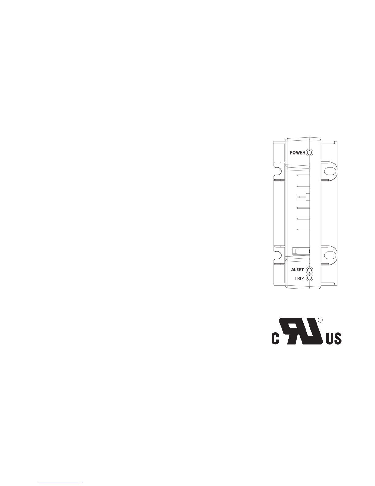
ALERT LED (Yellow): communicates an abnormal system
ALERT Flash Codes are shown in two tables on pages 8
6.0VA nominal (with solenoid on)
Alert module has been optimized for two stage UltraTech™ scroll systems.
Figure 1
Page 3
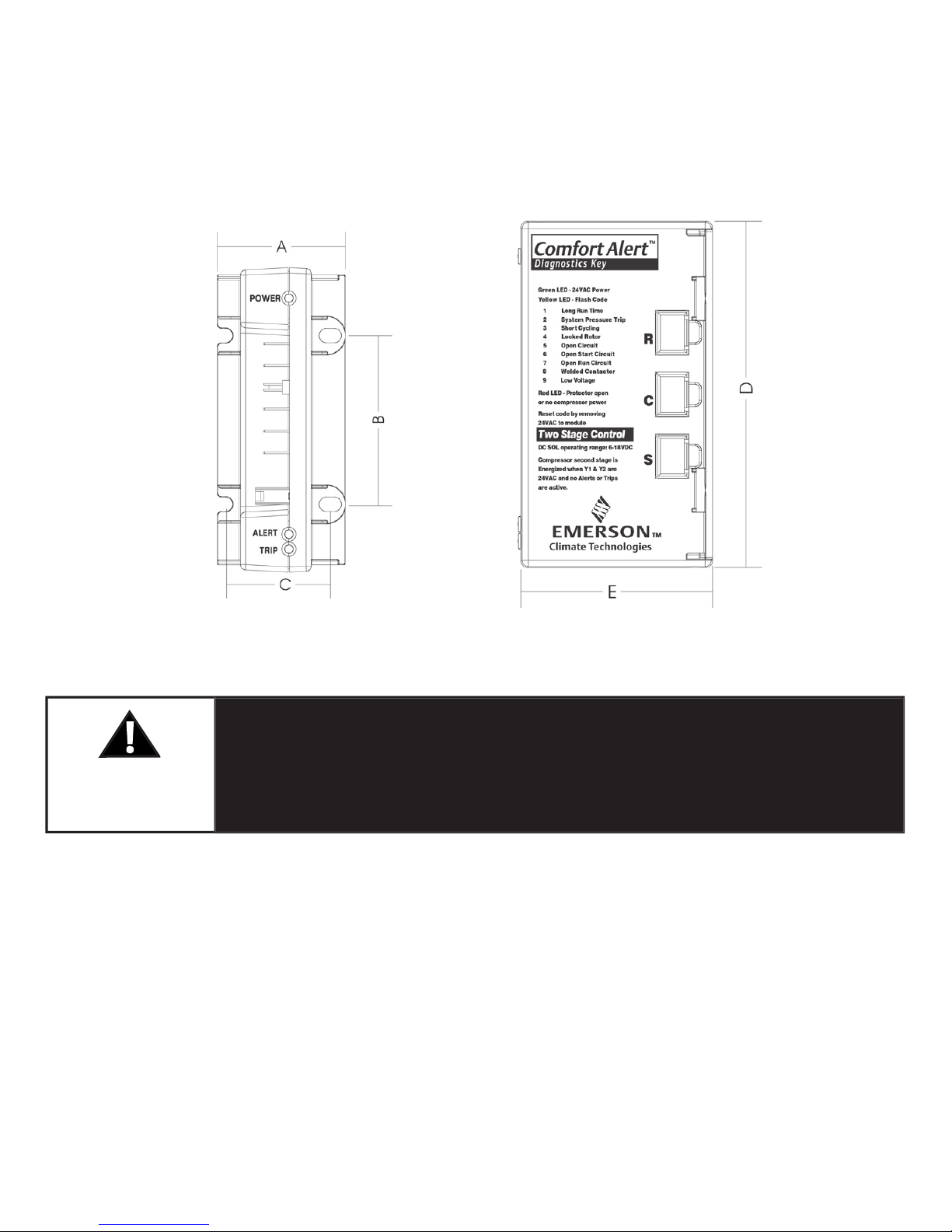
A. 1.85 in (47 mm) D. 4.40 in (112mm)
B. 2.44 in (62 mm) E. 2.44 in (62 mm)
C. 1.46 in (37 mm)
Hazardous voltage inside air conditioning system.
Disconnect power before installing or servicing module.
Module must be installed and serviced only by qualifi ed
personnel.
Page 4
After the thermostat demand signal is connected, verify Y is phased
properly with C by measuring 24VAC across Y and C when demand is present.
Page 5

Figure 4 Air Conditioning Schematic
Figure 5 Heat Pump Schematic
Two Stage Indoor Thermostat
Ultra Tech
Solenoid
529-0369-00
HPCO HTCO
CC
LPCO
Y2
Y
L
R
C
DC SOL
Y2
C
R
L
Y1
Comfort Alert
Diagnostics
Module
543-0033-00
Y2
C
R
L
Y1
Indoor Unit
Terminal Bloc
k
Two Stage Indoor Thermostat
Ultra T
ech
Solenoid
529-0369-00
HPCO HTCO
CC
LPCO
Y2
Y
L
R
C
DC SOL
Y2
C
R
L
Y1
Comfort Alert
Diagnostics
Module
543-0033-00
Y2
C
R
L
Y1
Indoor Unit
Terminal Bloc
k
Defrost
Boar
d
Page 6

Alert L terminal.
A voltmeter
Page 7

Interpreting The Diagnostic LEDs
When an abnormal system condition occurs, the Comfort Alert module displays the
appropriate ALERT and/or TRIP LED. The yellow ALERT LED will fl ash a number of
times consecutively, pause and then repeat the process. To identify a Flash Code
number, count the number of consecutive fl ashes. Every time the module powers
up, the last ALERT Flash Code that occurred prior to shut down is displayed for one
minute.
to verify
Alert. While Comfort Alert is off, reattach the wire to the Y terminal. Reapply power to
to verify the wiring.
for safety switch wiring.
Alert codes can be reset manu
All Heat Pump and Two Stage A/C
Page 8

Status LED Troubleshooting Information
Supply voltage is present at module terminals
Yellow “ALERT”
Yellow “ALERT”
Page 9

Status LED Troubleshooting Information
Yellow “ALERT”
Yellow “ALERT”
Yellow “ALERT”
Yellow “ALERT”
Yellow “ALERT”
Yellow “ALERT”
Yellow “ALERT”
Page 10

C terminals. Review
(page 4) for
R and C wiring.
(page 4) for R
and C wiring.
when off.
thermostat demand signal is present. If not, R and C are
reverse wired.
ALERT Flash Code 3 Verify Y terminal is connected to 24VAC at contactor coil.
ALERT Flash Code 5, 6 or 7 Check that compressor run and start wires are through
ALERT Flash Code 6 (Open Check that compressor run and start wires are routed
ALERT Flash Code 8 Determine if module’s Y terminal is connected. Verify Y
wired. Verify voltage at contactor coil falls below 0.5VAC
when off. Review
Y and C wiring
Page 11

Page 12

 Loading...