


399VP
Model 399VP
Combination pH/ORP Sensor
Instruction Manual
PN 51-399VP/rev.B
January 2005

CAUTION
SENSOR/PROCESS
APPLICATION COMPATIBILITY
The wetted sensor materials may not be
compatible with process composition
and operating conditions. Application
compatibility is entirely the responsibili-
ty of the user.
DANGER
HAZARDOUS AREA INSTALLATION
Installations near flammable liquids or in haz-
ardous area locations must be carefully evalu-
ated by qualified on site safety personnel. This
sensor is not Intrinsically Safe or Explosion
Proof.
To secure and maintain an intrinsically safe
installation, the certified safety barrier, trans-
mitter, and sensor combination must be
used. The installation system must comply
with the governing approval agency (FM,
CSA or BASEEFA/CENELEC) hazardous
area classification requirements. Consult your
analyzer/transmitter instruction manual for
details.
Proper installation, operation and servicing of
this sensor in a Hazardous Area Installation is
entirely the responsibility of the user.
ESSENTIAL INSTRUCTIONS
READ THIS PAGE BEFORE PROCEEDING!
Rosemount Analytical designs, manufactures, and tests its products to
meet many national and international standards. Because these instru-
ments are sophisticated technical products, you must properly install, use,
and maintain them to ensure they continue to operate within their normal
specifications. The following instructions must be adhered to and integrat-
ed into your safety program when installing, using, and maintaining
Rosemount Analytical products. Failure to follow the proper instructions
may cause any one of the following situations to occur: Loss of life; per-
sonal injury; property damage; damage to this instrument; and warranty
invalidation.
• Read all instructions prior to installing, operating, and servicing the prod-
uct. If this Instruction Manual is not the correct manual, telephone 1-800-
654-7768 and the requested manual will be provided. Save this
Instruction Manual for future reference.
• If you do not understand any of the instructions, contact your Rosemount
representative for clarification.
• Follow all warnings, cautions, and instructions marked on and supplied
with the product.
• Inform and educate your personnel in the proper installation, operation,
and maintenance of the product.
• Install your equipment as specified in the Installation Instructions of the
appropriate Instruction Manual and per applicable local and national
codes. Connect all products to the proper electrical and pressure
sources.
• To ensure proper performance, use qualified personnel to install, oper-
ate, update, program, and maintain the product.
• When replacement parts are required, ensure that qualified people use
replacement parts specified by Rosemount. Unauthorized parts and pro-
cedures can affect the product’s performance and place the safe opera-
tion of your process at risk. Look alike substitutions may result in fire,
electrical hazards, or improper operation.
• Ensure that all equipment doors are closed and protective covers are in
place, except when maintenance is being performed by qualified per-
sons, to prevent electrical shock and personal injury.
Emerson Process Management
Rosemount Analytical Inc.
2400 Barranca Parkway
Irvine, CA 92606 USA
Tel: (949) 757-8500
Fax: (949) 474-7250
http://www.raihome.com
© Rosemount Analytical Inc. 2005
About This Document
This manual contains instructions for installation and operation of the Model 399VP Combination
pH/ORP Sensor. The following list provides notes concerning all revisions of this document.
Rev. Level Date Notes
0 10/00 This is the initial release of the product manual. The manual has been reformatted to reflect the
Emerson documentation style and updated to reflect any changes in the product offering.
A 7/02 Added 1055 wiring diagrams.
B 1/05 Update flow cell info on pages 2 & 6.

MODEL 399VP pH/ORP TABLE OF CONTENTS
MODEL 399VP pH/ORP SENSOR
TABLE OF CONTENTS
SECTION TITLE PAGE
1.0 DESCRIPTION AND SPECIFICATIONS.......................................................... 1
1.1 Features and Applications................................................................................. 1
1.2 Physical Specifications...................................................................................... 1
1.3 Ordering Information ......................................................................................... 2
2.0 INSTALLATION ................................................................................................ 3
2.1 Unpacking and Inspection................................................................................. 3
2.2 Mounting ........................................................................................................... 3
2.3 Flow-Through Installation.................................................................................. 5
2.4 Insertion Installations ........................................................................................ 6
2.5 Submersion Installations .................................................................................. 7
3.0 WIRING............................................................................................................. 10
4.0 START-UP AND CALIBRATION ...................................................................... 19
4.1 Sensor Preparation ........................................................................................... 19
4.2 pH Calibration ................................................................................................... 19
4.3 ORP Calibration ................................................................................................ 20
5.0 MAINTENANCE................................................................................................ 21
5.1 General ............................................................................................................. 21
5.2 Automatic Temperature Compensator .............................................................. 21
5.3 pH Electrode Cleaning ...................................................................................... 22
5.4 ORP Platinum Electrode Check ........................................................................ 22
6.0 TROUBLESHOOTING...................................................................................... 23
7.0 RETURN OF MATERIAL.................................................................................. 24
i

MODEL 399VP pH/ORP TABLE OF CONTENTS
MODEL 399VP pH/ORP SENSOR
LIST OF FIGURES
Figure No. Title Page
2-1 Sensor Dimensions........................................................................................... 4
2-2 Model 399VP Shown in Various Flow-Through Installations............................. 5
2-3 Model 399VP Shown in Low Flow Cell Assembly............................................. 6
2-4 Model 399VP Shown in Various Insertion Installations ..................................... 6
2-5 Model 399VP With Insertion Adapter ................................................................ 7
2-6 Sensor Shown in Handrail Mounting Assembly ................................................ 8
2-7 Jet Spray Cleaner Used With Model 399VP ..................................................... 9
2-8 Junction Box and Pipe Mounting Accessory ..................................................... 9
3-1 Wire and Connector Pin Functions ................................................................... 11
3-2 Model 81 Wiring ................................................................................................ 11
3-3 Model 1181 Wiring ............................................................................................ 11
3-4 Model 54 Wiring Through a Remote Junction Box............................................ 11
3-5 Model 54 Wiring ................................................................................................ 12
3-6 Model 2081 Wiring ............................................................................................ 12
3-7 Model 1181, 1050/1060, 1003/1023 Wiring Through a Remote Junction Box.. 12
3-8 Model 2081 Wiring Through a Remote Junction Box........................................ 12
3-9 Model 81 Wiring Through a Remote Junction Box............................................ 13
3-10 Model 3081 and 4081 Wiring Through a Remote Junction Box........................ 13
3-11 Model 1055-22-32 Wiring.................................................................................. 13
3-12 Model 3081 and 4081 Wiring ............................................................................ 13
3-13 Model 1054 Wiring ............................................................................................ 14
3-14 Model 1054A/B and 2054 Wiring ...................................................................... 14
3-15 Model 1054 Wiring Through a Remote Junction Box........................................ 14
3-16 Model 1054A/B and 2054 Wiring Through a Remote Junction Box.................. 14
3-17 Model SCL-(P/Q) Wiring ................................................................................... 15
3-18 Model 2700 Wiring ............................................................................................ 15
3-19 Model 54epH Wiring.......................................................................................... 15
3-20 Model 1055-22-32 Wiring Through Remote Junction Boxes ............................ 15
3-21 Wiring Model 399VP-09 to Model 1055 (Pipe/Wall Mount)............................... 16
3-22 Wiring Model 399VP-09 to Model 1055 (Panel Mount)..................................... 17
3-23 Preparation of Raw Connecting Cable.............................................................. 18
LIST OF TABLES
Table No. Title Page
3-1 Remote Junction Box and Extension Cable Part Numbers............................... 10
4-1 ORP of Saturated Quinhydrone Solutions (in Millivolts).................................... 20
5-1 R
o
& R
1
Values for Temperature Compensation Elements .............................. 21
5-2 Temperature vs. Resistance of Auto TC Element.............................................. 21
ii
MODEL 399VP pH/ORP SENSOR SECTION 1.0
DESCRIPTION AND SPECIFICATIONS
SECTION 1.0.
DESCRIPTION AND SPECIFICATIONS
1.1 FEATURES AND APPLICATIONS
1.2 PHYSICAL SPECIFICATIONS
1.3 ORDERING INFORMATION
1
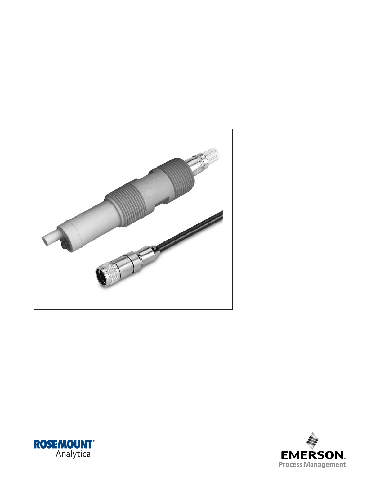
1.1 FEATURES AND APPLICATIONS
The Rosemount Analytical Model 399VP Sensor meas-
ures the pH or the Oxidation Reduction Potential
(ORP) of aqueous solutions in pipelines, open tanks,
or ponds. It is suitable for virtually all applications
where a low cost sensor is required. The combination
electrode features a ceramic junction constructed in
an annular design around the pH/ORP sensitive
membrane. The double or triple junction reference
cell configuration is resistant to process solutions
containing ammonia, chlorine, cyanides, sulfides, or
other poisoning ions.
The glass electrode is housed in a molded Tefzel
body and sealed with Viton
1
O-rings to guard against
process leakage. The cable end of the sensor is also
sealed, eliminating cable shorts caused by exposure
to moisture. This construction makes for a highly
chemical resistant disposable sensor and does not
require electrolyte replenishment.
The custom glass electrode is available with either a
standard hemi bulb or an optional flat bulb to best
meet your application needs. Flat glass is advanta-
geous in abrasive or coating applications that etch or
build up on the glass respectively. In coating applica-
tions, such as slurries, the flat surface allows the
process flow to act as a scrubbing agent to reduce
coating and maintenance whereas in abrasive appli-
cations pitting from silicates and other similar materi-
als is minimized by the flat surface to provide longer
life. The hemi bulb is ideal for general purpose use
and for those processes requiring greater accuracy
over the entire pH range
Installation is easily achieved through the wide variety
of mounting configurations. The Model 399VP fea-
tures 1 in. (MNPT) front and rear facing connections
for insertion, submersion or flow through pH and ORP
applications.
1.2 PHYSICAL SPECIFICATIONS
Materials of Construction: Tefzel, glass, ceramic
and Viton (also, Platinum for ORP sensor)
Process Connections: 1 in. MNPT
Interconnecting Cable: None - must use mating VP
cable
Measured Range: pH: 0-14*
ORP: –1500 -+1500mV
*Percent Linearity over pH range:
Temperature Compensation: Automatic 0 to 85°C
(32° to 185°F) (Temperature compensation is not
required for 399 ORP when used with Models 1060,
1023 or 1181 ORP)
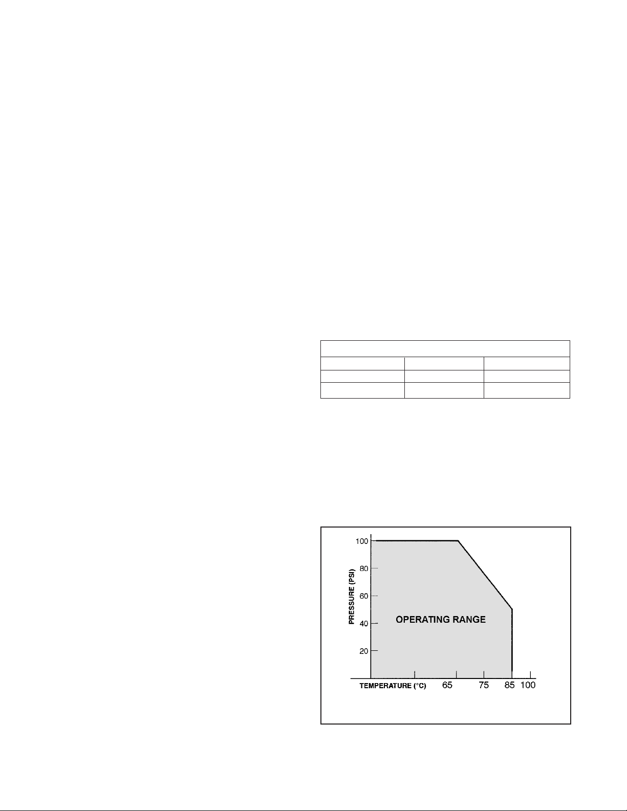
Maximum Pressure: 790 kPa abs (100 psig) at 65°C
(Refer to Graph A below)
Weight/Shipping Weight: 0.45 kg/0.9 kg (1 lb/2 lb)
1
Registered trademarks of E. I. du Pont de Nemours and Company.
Hemi Bulb Flat Bulb
1-2 pH 94% 93%
2-12 pH 99% 98%
12-13 pH 97% 95%
GRAPH A. Pressure/Temperature Limitations
for Model 399VP

MODEL 399VP pH/ORP SENSOR SECTION 1.0
DESCRIPTION AND SPECIFICATIONS
1.3 ORDERING INFORMATION
The Model 399VP pH/ORP Sensor is available with custom glass electrodes housed in a molded Tefzel body with
1 in. MNPT threads suitable for insertion, submersion or flow through installation. The sensor includes a general
purpose hemi bulb pH electrode (flat bulb optional) or a platinum ORP electrode and a double or triple junction gel
filled reference electrode. Automatic temperature compensation is standard with the Model 399VP pH, but is not
required on the Model 399VP ORP (except when used with the Model 1054A ORP Microprocessor Analyzer). The
399VP is offered with the Variopol (VP) connector and uses a mating VP cable (purchased separately). A remote
preamplifier must be used with this sensor.
2
Code 399VP pH (GPLR hemi bulb) Preamplifier/Cable (Required Selection)
02 3K ohm TC (Models 1181, 1050, and 1003)
09 Pt100 TC (Models 54pH, 1054A/B, 1055, 2054, 2081 pH, 81, 3081, and 4081)
Code Glass Type (optional - choose one; not valid with special application codes)
11 High pH
15 HF Resistant
71 GPLR Flat bulb
Code Special Applications - valid with only standard hemi glass (optional - choose one)
301 Low ionic strength water
302 Heavy reference poisoning ions (triple reference junction)
303 High temperature spikes or Low temperature storage
33 ORP sensor
PN Mating VP Connector Cable (required for all new installations)
23645-06 15 ft cable with mating VP connector, prepped with BNC on analyzer end
23645-07 15 ft cable with mating VP connector, prepped without BNC on analyzer end
MODEL
399VP pH/ORP SENSOR
1. Mounting Accessories (optional)
Choose one: PN 23242-02, Mounting adapter kit, 1/2 in. MNPT process connection, 1 in. x 3/4 in. sensor adapter
PN 915240-03, PVC flow through tee, 3/4 in. NPT process connection
PN 915240-04, PVC flow through tee, 1 in. NPT process connection
PN 915240-05, PVC flow through tee, 1-1/2 in. NPT process connection
PN 24091-00, Acrylic low flow cell
PN 2002011, 1-1/2 in. CPVC tee with 1-in. FNPT connection
PN 9330022, Pipe mount union, 1 in. x 1 in. CPVC (for sensor to analyzer distance extension)
PN 11275-01, Sensor handrail assembly
PN 1000857, Handrail mounting kit (pipe and sensor coupling supplied by others)
2. Junction Boxes (optional)
Remote Junction Boxes (to extend sensor to analyzer distances)
Choose one: PN 23555-00, includes preamplifier for Models 54, 81, 3081, 4081; NEMA 4X
PN 22719-02, Weatherproof junction box for cable extension
PN 23309-03, use with 1181 and 1050 compatible preamplifier
PN 23309-04, use with 1054/A/B, 2054, 2081 compatible preamplifier
3. Preamplifiers (used to amplify signal when mounting sensor further than 15 ft from the analyzer)
Choose one: PN 22698-02, Plug in preamplifier, 1181/1050 compatible (use with junction box PN 23309-03)
PN 22698-03, Plug in preamplifier, 1054/1054A/1054B/2054/ 2081 compatible (use with junction box PN 23309-04)
4. Extension cables (used with remote junction boxes)
Choose one: PN 23646-01, 11 conductor cable, shielded, prepped
PN 9200000, 4 conductor cable, shielded, unprepped
5. Other optional accessories
Choose one: PN 12707-00, Jet spray cleaner
PN 2001492, Stainless steel tag, specify marking (formerly Code -11)
PN 9210012, Buffer solution, 16 oz, 4.01 pH
PN 9210013, Buffer solution, 16 oz, 6.86 pH
PN 9210014, Buffer solution, 16 oz, 9.18 pH
PN 22698-00, Plug-in preamplifier, 1003 compatible
FOR FIRST TIME 399VP* INSTALLATIONS, WE RECOMMEND USING THE FOLLOWING GUIDE:
* Also requires mating VP cable — see 399VP Ordering Information above.

MODEL 399VP pH/ORP SENSOR SECTION 2.0
INSTALLATION
SECTION 2.0.
INSTALLATION
2.1 UNPACKING AND INSPECTION
2.2 MOUNTING
2.3 FLOW-THROUGH INSTALLATIONS
2.4 INSERTION INSTALLATIONS
2.5 SUBMERSION INSTALLATIONS
2.1 UNPACKING AND INSPECTION.
Inspect the carton for any damage. If damage is
detected, contact the carrier immediately. Inspect the
hardware. Make sure all the items on the packing list
are present and in good condition. Notify the factory
if any part is missing. If the sensor is in satisfactory
condition, proceed to Section 2.2, Mounting.
NOTE
Save the packing cartons and materials as
most carriers require proof of damage due to
mishandling, etc. Also, if it is necessary to
return the sensor to the factory, you must pack
the sensor in the same manner as it was
received. Refer to Section 7.0 for instructions.
If storing the sensor, the vinyl boot should be
filled with pH buffer solution (pH 4 buffer rec-
ommended) and replaced on sensor tip until
ready to use.
CAUTION
Buffer solution in the vinyl boot may cause
skin or eye irritation.
NOTE
Glass electrode must be wetted at all times (in
storage and in line) to maximize sensor life.
2.2 MOUNTING.
The sensor has been designed to be located in
industrial process environments. Temperature and
pressure limitations must not be exceeded at any
time. A pertinent caution label is attached to the sen-
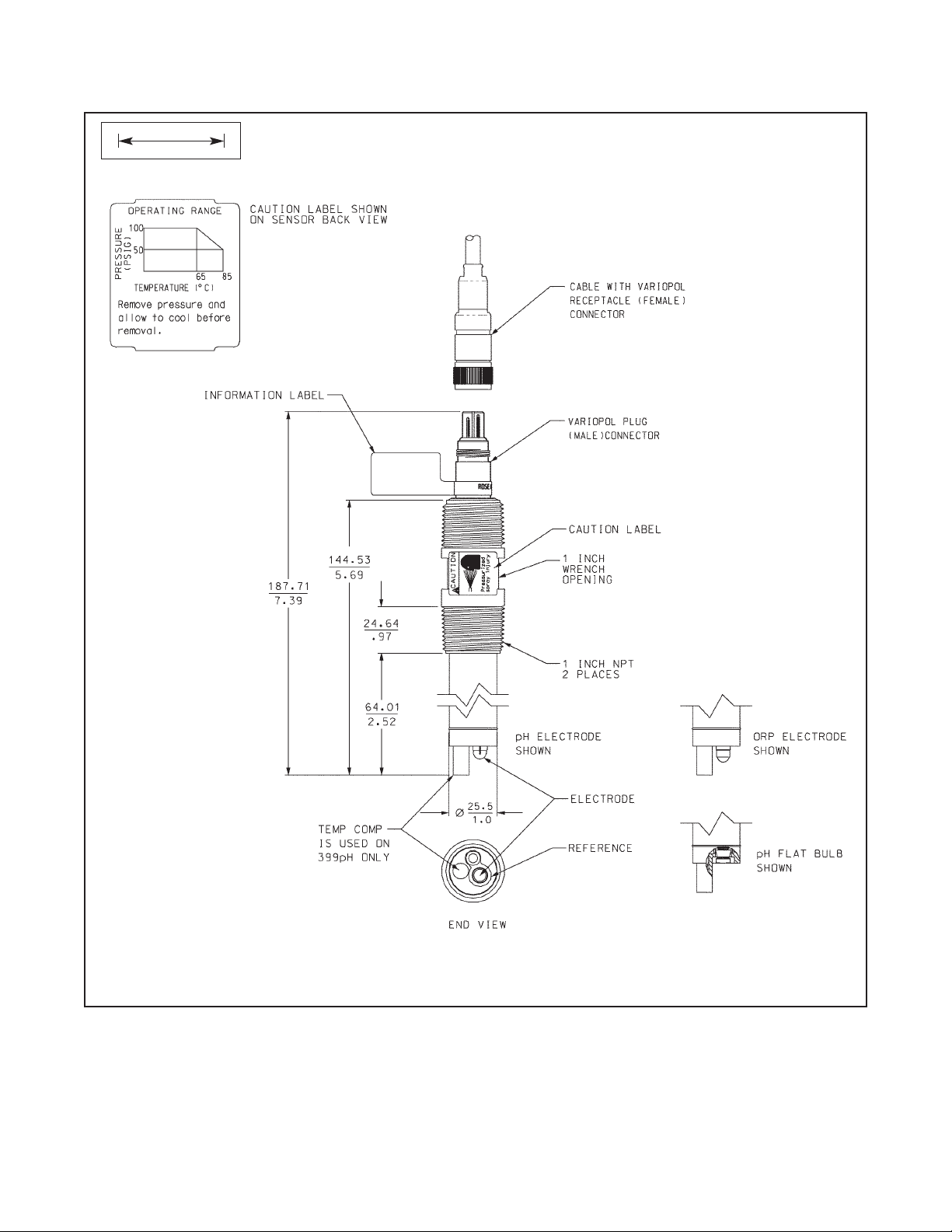
sor. Please do not remove the label. See Figure 2-1.
CAUTION
Internal electrolyte fill solution may cause skin
or eye irritation.
Mounting Guidelines:
1. Shake down the sensor to remove any air bub-
bles that may be present inside the tip of the pH
glass.
2. Do not install the sensor horizontally. The sensor
must be at a minimum of 10° off the horizontal
(sensor glass bulb pointing down) to ensure
accuracy.
3. Do not install the sensor upside down.
4. Air bubbles may become trapped on the sensor
glass bulb. This problem is most commonly
encountered in areas of low flow or during cali-
bration. Shake the probe while immersed in solu-
tion to remove bubbles.
In most cases, the pH sensor can simply be installed
as shipped, and readings with an accuracy of ± 0.6
pH may be obtained. To obtain greater accuracy or
to verify proper operation, the sensor must be cali-
brated together with its compatible analyzer or trans-
mitter.
3
MODEL 399VP pH/ORP SENSOR SECTION 2.0
INSTALLATION
4
FIGURE 2-1. Sensor Dimensions
INCH
MILLIMETER

MODEL 399VP pH/ORP SENSOR SECTION 2.0
INSTALLATION
2.3 FLOW-THROUGH INSTALLATIONS.
The Model 399VP Sensor has a 1 in. MNPT process connection at the front and back end of the sensor for mount-
ing directly into a 1 in. or 1½ in. tee. See Figure 2-2 for installation configurations. It is recommended that shut-off
valves be provided for sensor removal and service.
NOTE
Large pipe wrenches must not be used to tighten the sensor into a flange or other type of mounting.
FIGURE 2-2. MODEL 399VP SHOWN IN VARIOUS FLOW THROUGH INSTALLATIONS
See Section 1.3 for a complete listing of tees.
Model 399VP shown in Tee PN 915240-03, -04, or -
05. Tee is available with 3/4 in., 1 in., or 1-1/2 in.
NPT process connection threads.
Model 399VP shown in Tee PN 2002011. Tee is
available with 1 in. process connection threads.
Side view of Tee PN 2002011 with Model 399VP
shown in middle of process flow.
Side view of Tee PN 915240-03, -04, or -05 with
Model 399VP shown in middle of process flow.
5

6
MODEL 399VP pH/ORP SENSOR SECTION 2.0
INSTALLATION
2.4 INSERTION INSTALLATIONS.
The Model 399VP sensor has forward and rear facing 1 in. MNPT process connections for pipeline installations
(see Figure 2-4 or 2-5) and flange connections. The Model 399VP is also suitable for side-of-tank installation. The
Model 399VP must be mounted at least 10° above the horizontal (see Figure 2-4).
NOTE
Large pipe wrenches must not be used to tighten the sensor into a flange or other type of mounting.
FIGURE 2-4. MODEL 399VP SHOWN IN VARIOUS INSERTION INSTALLATIONS
Model 399VP can be mounted using front or back threads to install
sensor with flange into process. Flange is supplied by others.
FIGURE 2-3. MODEL 399VP SHOWN IN LOW FLOW CELL ASSEMBLY (PN 23728-00)
The see-through flow cell is
perfect for processes where
flow regulation is desired.
Tubing (1/4 inch) is needed for
connection to the process or
sample stream.
 Loading...