

Emerson Bettis RGS Q-Series, Bettis Q205, Bettis Q210, Bettis Q214, Bettis Q203 Installation, Operation And Maintenance Manual
...Page 1
Installation, Operation and Maintenance Manual
Bettis RGS Q-Series
Double-Acting Actuators
RGS011110-1 Rev. 0
November 2015
Page 2

Page 3

Installation, Operation and Maintenance Manual
RGS011110-1 Rev. 0
Table of Contents
Section 1: Overview ��������������������������������������������������������������1
Section 2: Installation �����������������������������������������������������������2
2.1 Valve Attachment ........................................................................................ 3
2.2 Accessory Mounting .................................................................................... 4
2.3 Piping and Operation ................................................................................... 4
2.4 Travel Adjustment ........................................................................................ 7
Section 3: Troubleshooting ������������������������������������������������ 10
Section 4: Maintenance
4.1 Periodic Maintenance Schedule ..................................................................11
4.2 Lubrication..................................................................................................11
4.3 Maintenance Kit ......................................................................................... 12
4.4 Piston Seal Replacement ............................................................................ 12
4.5 Body Maintenance ..................................................................................... 15
Table of Contents
November 2015
Appendix A: ������������������������������������������������������������������������22
A.1 Dual Cylinder Model .................................................................................. 22
A.2 Single Cylinder Model ............................................................................... 24
Table of Contents
I
Page 4

Section 1: Overview
November 2015
Section 1: Overview
NOTE:
All activities must be carried out in order to ensure proper actuator operation.
Always read all instructions before beginning maintenance.
Bettis RGS Q-Series actuators are composed of two or three basic sub-assemblies, one or
two force modules and a torque module. The force module contains the piston and rack
which provide linear motion. The torque module contains the gear which converts the
force modules’ linear motion into torque and operates the valve.
Every actuator assembled by Bettis is tested prior to shipment to our customers.
Order specific documentation may be available upon request.
Installation, Operation and Maintenance Manual
RGS011110-1 Rev. 0
1
Overview
Page 5
Installation, Operation and Maintenance Manual
RGS011110-1 Rev. 0
Section 2: Installation
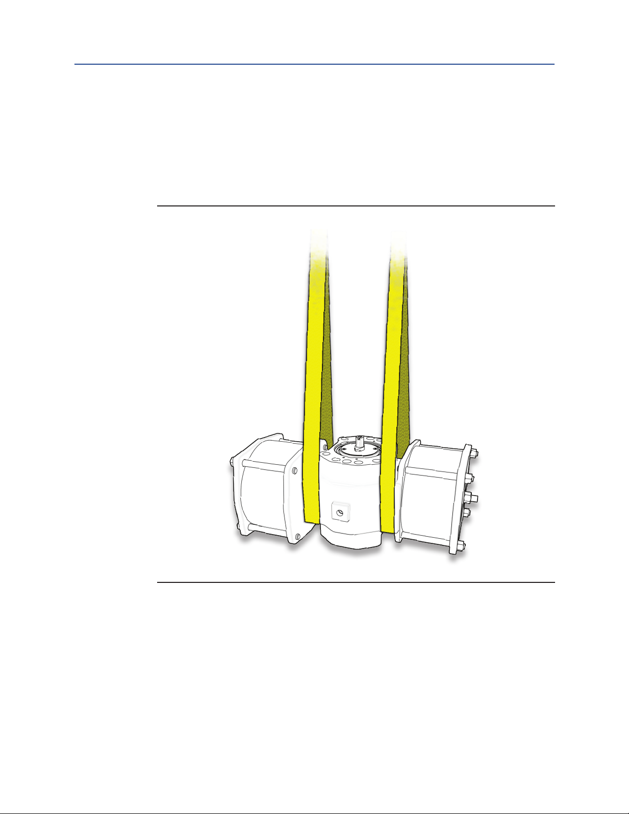
Bettis actuators may be mounted in any position/orientation. If necessary, lift the actuator
with straps placed inside the framework of the body. Never lift the actuator by the cylinders,
tie rods, or travel stops. Lifting the actuator with the valve attached is not generally
recommended.
Figure 1
Section 2: Installation
November 2015
Installation
2
Page 6
Section 2: Installation
November 2015
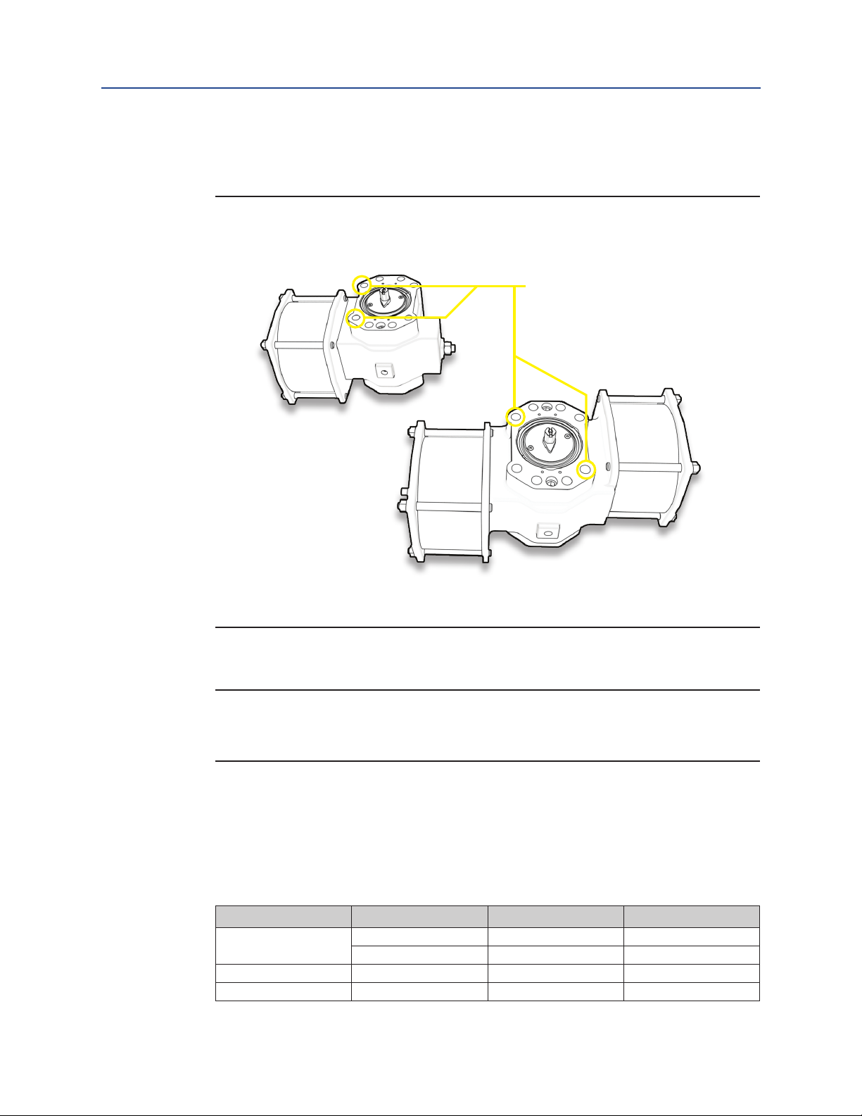
Threaded Lifting Eyes
Lifting eyes may be threaded into the body section and be used to lift the actuator.
Figure 2
Installation, Operation and Maintenance Manual
RGS011110-1 Rev. 0
2�1 Valve Attachment
NOTE:
Prior to mounting the actuator, verify alignment of coupler and shaft to ensure that the
valve will move to correct position.
Ensure the actuator is in the same position as the valve. It may be necessary to stroke the
actuator to determine the correct mounting orientation. Attach the actuator to the valve using
the proper bracket and coupler, or with a Bettis Universal Mounting Plate (UMP) if provided.
Using all mounting holes indicated on Bettis dimensional drawings, tighten all fasteners hand
tight, then torque the fasteners to the corresponding value on the table below.
Table 1�
Thread Pattern Ft-Lbs Nm
Q203/204/205
Q207/210 M10 32 43
Q212/214 M20 235 318
3
M6 7 9
M8 16 22
Installation
Page 7

Installation, Operation and Maintenance Manual
RGS011110-1 Rev. 0
2�2 Accessory Mounting
As a standard, Bettis RGS Q-Series actuators are provided with NAMUR slotted accessory
mounting geometry. When installing accessories, such as switch boxes or positioners,
tighten accessory mounting bolts hand tight, stroke the actuator three times to ensure
proper alignment, then tighten the accessory mounting bolts to the proper torque.
Check the dimensional drawing or associated product data sheet for exact dimensions.
2�3 Piping and Operation
The operation of a Bettis RGS Q-Series Double-Acting (DA) actuator is comparable to any
double-acting rack and pinion actuator.
Instrument air, water, and other power gases and fluids may be used to cycle the actuator so long
as construction materials were chosen accordingly during assembly and maximum allowable
pressure is not exceeded. Air driven stainless-steel actuators with stainless-steel
or composite cylinders are not harmed by wet air (so long as freezing does not occur).
Aluminum and chrome-plated steel cylinders may be harmed over time by the presence of water.
Section 2: Installation
November 2015
WARNING: DO NOT EXCEED PRESSURE RATING
Exceeding the stated maximum pressure may result in damage to equipment and danger
to personnel including severe injury or death. Consult the actuator label for operating
limits. If an actuator label is missing, contact Bettis to request a replacement.
WARNING: DO NOT EXCEED TEMPERATURE RATING
Operating outside of the minimum and maximum temperature range may result in damage
to equipment and danger to personnel including severe injury or death. Consult the
actuator label for operating limits. If an actuator label is missing, contact Bettis to request a
replacement. An example of an actuator label is provided below for your reference.
Installation
NOTE:
CE marking indicates product conforms to the requirements of applicable directives as
listed on the actuator label.
4
Page 8

Section 2: Installation
November 2015
All Bettis actuators are shipped in the fail clockwise (Left-Hand) orientation unless
ordered as fail counterclockwise (Right-Hand). The orientation may be reversed in the
field by moving all accessories to the opposite side of the shaft and turning the actuator
top–side down.
Double-Acting (Left-Hand): pressure on the end cap ports pushes the pistons inward
and causes counterclockwise rotation. Pressure to the base plate ports pushes the
pistons outward resulting in a clockwise rotation.
Double-Acting (Right-Hand): pressure on the end cap ports pushes the pistons inward
and causes clockwise rotation. Pressure to the base plate ports pushes the pistons
outward resulting in a counterclockwise rotation.
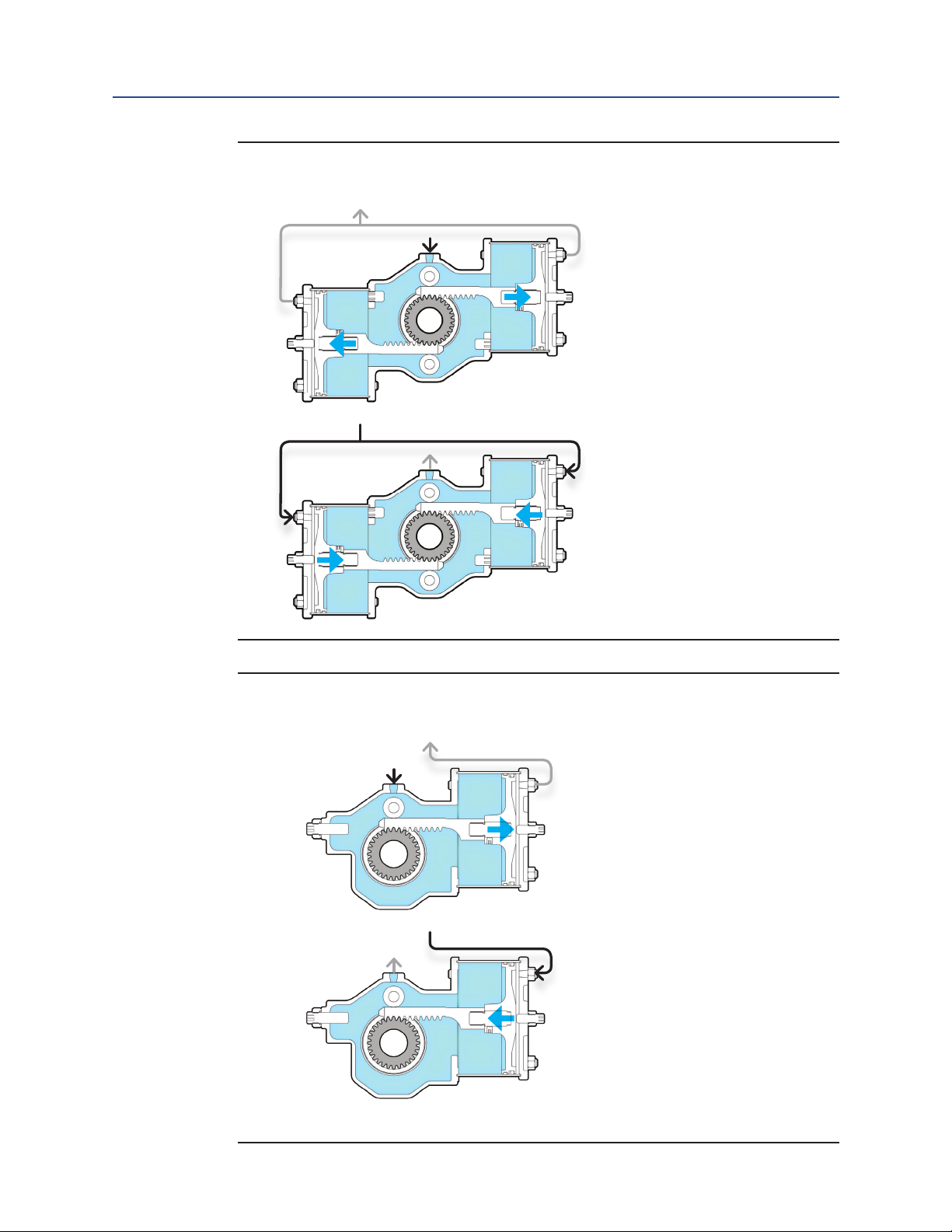
Figure 3
Installation, Operation and Maintenance Manual
RGS011110-1 Rev. 0
Left-Hand
Right-Hand
Piping Guidelines:
• For dual cylinder models (205, 210, and 214), both end cap pressure ports
(P1 and P2) must be utilized for proper operation.
• P1 and P2 are typically connected together and powered by a single air pathway.
• For single cylinder models (203, 204, 207, and 212), P2 does not exist.
• P3 is a pressure port on the body.
5
Installation
Page 9
Installation, Operation and Maintenance Manual
RGS011110-1 Rev. 0
Figure 4
205DA, 210DA, 214DA
P3
P2
P3
Section 2: Installation
November 2015
P1
P1
P2
Figure 5
203DA, 204DA, 207DA, 212DA
P3
P1
P3
P1
Installation
6
Page 10

Section 2: Installation
November 2015
Installation, Operation and Maintenance Manual
2�4 Travel Adjustment
The following instructions are for Left-Hand orientated actuators. For non-standard
models, clockwise and counterclockwise motion will be the inverse of what is described
below. Check the actuator model and orientation before adjusting the Travel Stops.
Figure 6
Travel Stop
B-1
Travel Stop
A-1
205DA, 210DA, 214DA
RGS011110-1 Rev. 0
Travel Stop
A-2
Figure 7
Travel Stop
B
Travel Stop
B-2
Travel Stop
203DA, 204DA, 207DA, 212DA
A
7
Installation
Page 11

Installation, Operation and Maintenance Manual
RGS011110-1 Rev. 0
Set Clockwise Rotation (Travel Stop(s) A)
1. Relieve all pressure from the actuator.
2. Loosen Travel Stop Nut(s) on Travel Stop(s) A. Be careful not to misplace the
travel stop O-ring(s).
3. Ensure actuator lockout (if provided) is disengaged.*
Single Cylinder Actuators:
a. Adjust Travel Stop A until set at the desired position. It may be neces-
sary to stroke the actuator in the clockwise direction between each
adjustment. This can be accomplished by applying pressure to P3.
b. With pressure still applied to P3, tighten the travel stop nut until it
comes in contact with the end cap, then an additional quarter turn.
Dual Cylinder Actuators:
Section 2: Installation
November 2015
a. Unthread Travel Stop A-1 three to four full turns.
b. Adjust Travel Stop A-2 until the stroke is set to the desired position.
It may be necessary to stroke the actuator in the clockwise direction
between each adjustment. This can be accomplished by applying
pressure to P3.
c. With pressure applied to P3, thread Travel Stop A-1 in until it is in firm
contact with the piston.
d. With pressure still applied to P3, tighten both travel stop nuts until it
comes in contact with the end cap, then an additional quarter turn.
* Clockwise rotation of the travel stop will shorten actuator stroke (stroke < 90°),
counterclockwise rotation will lengthen actuator stroke (stroke > 90°).
Installation
8
Page 12

Section 2: Installation
November 2015
Set Counterclockwise Rotation (Travel Stop(s) B)
1. Relieve all pressure from the actuator.
2. Ensure actuator lockout (if provided) is disengaged.*
Single Cylinder Actuators:
Dual Cylinder Actuators:
Installation, Operation and Maintenance Manual
RGS011110-1 Rev. 0
a. Loosen the travel stop nut on Travel Stop B. Be careful not to misplace
the travel stop O-ring.
b. Adjust Travel Stop B until the stroke is set to the desired position. It may be
necessary to stroke the actuator in the counterclockwise direction between
each adjustment. This can be accomplished by applying pressure to P1.
c. With pressure applied to P1, tighten the travel stop nut until it comes in
contact with the body.
If counterclockwise travel adjustment on a dual cylinder actuator is required in the
field, it is recommended the user accomplish this via bracket motion followed
by resetting Travel Stops A via the directions listed above. If this cannot be
accomplished, follow the steps below.
WARNING: DEPRESSURIZE COMPONENTS PROPERLY
Do not remove/loosen tie rod nuts unless cylinder is fully depressurized.
Components may exit the actuator dangerously if disassembly is attempted under pressure.
a. Follow Section 4.4, Steps 1 to 3.
b. Adjust each Travel Stop B the appropriate amount. Use the table below as a
guide as travel cannot be checked without fully assembling the actuator.
Table 2�
Model Degrees of Travel Per 1/4 Turn
Q205 1.4
Q210 1.1
Q214 0.8
c. Measure the height of both Travel Stops B protruding through the body
and ensure that they are equal.
#
d. Follow Section 4.5, Steps 16 to 20.
* Clockwise rotation of the travel stop will shorten actuator stroke (stroke < 90°),
counterclockwise rotation will lengthen actuator stroke (stroke > 90°).
# These travel stops were installed with thread locker and may require an application of
heat before they may be adjusted. It is recommended the user reapply thread locker after
their adjustment.
9
Installation
Page 13

Installation, Operation and Maintenance Manual
RGS011110-1 Rev. 0
Section 3: Troubleshooting
Table 3�
ISSUE CAUSE SOLUTION
Supply pressure too low
Irregular or Stuttering Stroke
Leakage
Improper Travel
Operating/Stroking too slowly
Worn internal components See Section 4.4 to 4.5
Damaged or valve Consult valve manufacturer
Travel stop nut is not tight
Damaged Piston O-ring See Section 4.4
Damaged shaft seals See Section 4.5
Damaged cylinder seals See Section 4.4
Travel stops are not correctly set See Section 2.4
Internal cylinder contaminants
preventing normal stroke
Damaged valve Consult valve manufacturer
Supply pressure too low
Internal cylinder contaminants
preventing normal stroke
Damaged valve Consult valve manufacturer
Damaged seals or O-rings causing
loss of pressure
Damaged supply lines
Limitation of accessories or port size Upgrade accessories or port size
Section 3: Troubleshooting
November 2015
Verify operating pressure is
correct
Tighten travel stop nut with
pressure relieved from actuator
See Section 4.4 to 4.5
Verify operating pressure
will supply torque needed to
operate valve correctly
See Section 4.4
See Sections 4.4 to 4.5
Inspect supply and lines re-
place as needed
Troubleshooting
10
Page 14

Section 4: Maintenance
November 2015
Installation, Operation and Maintenance Manual
Section 4: Maintenance
4�1 Periodic Maintenance Schedule
General service actuators do not require periodic maintenance. Severe service actuators
may require periodic maintenance based on operating conditions. Severe service
may include but is not limited to high speed, high cycle, highly corrosive, explosive
atmosphere, and others. Special applications may require individual maintenance
schedules. Contact Bettis for help developing a maintenance schedule for your application.
NOTE:
This product is only intended for use in large-scale fixed installations excluded from the
scope of Directive 2011/65/EU on the restriction of the use of certain hazardous
substances in electrical and electronic equipment (RoHS 2).
RGS011110-1 Rev. 0
4�2 Lubrication
Bettis actuators are lubricated for life. For special applications, grease fittings may be
provided. Use the grease fittings (if applicable) incorporated into the torque module of
your actuator to apply additional lubricant. The frequency of this lubrication will depend
on the application of the actuator. For any questions regarding the frequency of this
operation or appropriate lubrication compounds, contact your Bettis distributor.
WARNING: DEPRESSURIZE COMPONENTS PROPERLY
Do not remove/loosen tie rod nuts unless cylinder is fully depressurized.
Components may exit the actuator dangerously if disassembly is attempted under pressure.
Ensure that all process lines are safe.
Read all maintenance instructions before starting work.
NOTE:
Performing piston seal replacement on one cylinder at a time will allow maintenance
while retaining travel stop adjustment. If both cylinders will be removed at the same
time, the travel stops must be fully unthreaded prior to removing the end caps. Leaving
the travel stops in place will put spring pressure on the end cap when it is removed,
which could cause serious injury or death.
11
Maintenance
Page 15

Installation, Operation and Maintenance Manual
RGS011110-1 Rev. 0
4�3 Maintenance Kit
To purchase your actuator maintenance kit, contact your Bettis distributor. Please have
the serial number of your actuator available. This number may be found on the actuator
label or stamped into the body of the actuator.
4�4 Piston Seal Replacement
1. Exhaust all pressure and disconnect all supply lines.
2. Loosen all tie rod nuts until they are flush with the ends of the tie rods.
3. Check that there is no pressure against the end cap by verifying that the end
cap is not being forced against the tie rod nuts.
WARNING: EXHAUST ALL PRESSURE AGAINST END CAP
Section 4: Maintenance
November 2015
If there is force against the end cap, stop. Do not continue further until it is assured that the
unit is safe to disassemble.
4. Remove the end cap. Be careful not to lose the cylinder seal located on the
internal side of the end cap.
Figure 8
5. Remove the cylinder. Be careful not to damage the internal surface of the
cylinder as this will compromise the piston’s ability to seal.
Figure 9
Maintenance
12
Page 16

Section 4: Maintenance
November 2015
6. Replace the piston O-ring and wiper ring as needed. Be sure to lubricate the new
O-ring and wiper ring with the correct Bettis approved lubricant if they are
replaced.
Figure 10
Installation, Operation and Maintenance Manual
RGS011110-1 Rev. 0
Piston
Piston O-ring
Wiper Ring
7. Inspect the piston bolt for any corrosion or wear (pitting, cracking). If excessive
corrosion or wear is apparent, a new actuator or actuator components may
be necessary.
8. Lubricate the internal surface of the cylinder with a light coat of the correct
Bettis approved lubricant and slide the cylinder back over the piston and into the
cylinder seal groove of the base plate, taking care not to pinch the piston O-ring.
Figure 11
13
Maintenance
Page 17

Installation, Operation and Maintenance Manual
RGS011110-1 Rev. 0
9. Place the end cap back over the tie rods. Be sure that the cylinder is seated
in the cylinder seal groove of the end cap with the cylinder seal still in place
between the cylinder and the end cap.
10. Secure the end cap with the tie rod hex nuts you removed in step two.
Hand tighten, and then torque the hex nuts to half and then full values
according to the table below using the pattern designated.
Table 4�
Model Ft-Lbs Nm
203 10 14
204/205 10 14
207/210 20 27
212/214 35 48
Figure 12
1 4
4 Bolt
Pattern
23
Section 4: Maintenance
November 2015
11. Complete Steps 1 to 10 on the second force module of the actuator
(dual cylinder models).
12. Leak Test.
13. Reinstate the actuator to service.
Maintenance
14
Page 18

Section 4: Maintenance
November 2015
Installation, Operation and Maintenance Manual
4�5 Body Maintenance
To perform this maintenance, the actuator must be removed from the valve.
1. Follow Section 4.5, Steps 1 to 5.
2. Remove the top hat assembly by removing the top hat mounting bolts.
Figure 13
RGS011110-1 Rev. 0
3. Remove the piston assembly(s) by pulling away from body of actuator. If model
is a dual cylinder, this may require two people. Rotate the shaft until the teeth
of the shaft and rack are no longer engaged.
Figure 14
4. Clean and inspect rack teeth for wear. If teeth are excessively worn, a new
rack(s) may be necessary for continued reliable/safe operation.
5. Remove retainer ring and thrust washer from top side of shaft.
15
Maintenance
Page 19

Installation, Operation and Maintenance Manual
RGS011110-1 Rev. 0
Figure 15
6. Push shaft through top of shaft hole (shaft will only exit body in one direction).
If necessary, a drive key may be inserted into the bottom of the shaft and
tapped with a hammer to free the shaft from the body.
Section 4: Maintenance
November 2015
Figure 16
7. Remove bushings and O-rings from shaft and actuator body.
8. Clean and inspect the shaft for wear. If wear is found, a new shaft or actuator
may be necessary for further safe/reliable operation.
Maintenance
16
Page 20

Section 4: Maintenance
November 2015
Reassembly:
9. Lubricate and install O-ring(s), saddle pin(s), saddle pin thrust washers and roller(s).
10. Lightly coat all O-rings and bushings with lubricant.
11. Install O-rings on internal and external surfaces of bushing(s) in respective
O-ring grooves.
Figure 17
Installation, Operation and Maintenance Manual
RGS011110-1 Rev. 0
17
12. Insert one bushing into bottom side of shaft hole (side which contains shoulder
to prevent bushing from falling out). The bushing should be placed with external
O-ring closer to the center of the body of the actuator.
Figure 18
Maintenance
Page 21

Installation, Operation and Maintenance Manual
RGS011110-1 Rev. 0
13. Place shaft shoulder washer on top of bushing and insert shaft through top of
shaft hole (shaft shoulder washers not applicable for 203, 204, and 205 models).
Figure 19
Section 4: Maintenance
November 2015
Maintenance
14. Insert second shaft shoulder washer on top of shaft, followed by bushing
(already containing both O-rings) again with external O-ring closer to the center
of the body of the actuator (shaft shoulder washers not applicable to 203, 204,
and 205 models).
18
Page 22

Section 4: Maintenance
November 2015
Figure 20
Internal O-ring
External O-ring
Bushing
Shoulder Washer
Shaft
Shoulder Washer
Installation, Operation and Maintenance Manual
RGS011110-1 Rev. 0
Bushing
External O-ring
Internal O-ring
15. Place thrust washer (not applicable on 203, 204, 205) on top of bushing
followed by retaining ring. Ensure the retaining ring is seated in groove.
16. Rotate shaft until positioning markers are in the position shown below.
Note the orientation of the body NPT port as well as the orientation of the high
and low sides of the actuator.
19
Maintenance
Page 23

Installation, Operation and Maintenance Manual
RGS011110-1 Rev. 0
Figure 21
Section 4: Maintenance
November 2015
NPT Pressure Port
Shaft Positioning Markers
Q214, Q212
Shaft Positioning Marker
NPT Pressure Port
Shaft Positioning Markers
NPT Pressure Port
Q210, Q207
Shaft Positioning Markers
NPT Pressure Port
Maintenance
Q203
Q205, Q204
20
Page 24

Section 4: Maintenance
November 2015
Figure 22
Single Cylinder Models:
a. Insert the piston and engage rack teeth with shaft teeth after ensuring
b. Press inward on piston until the point of refusal.
Dual Cylinder Models:
Installation, Operation and Maintenance Manual
RGS011110-1 Rev. 0
proper alignment.
a. Simultaneously insert the pistons and align teeth on racks and shafts.
b. Simultaneously press both pistons into the body engaging the rack and
shaft teeth until the point of refusal.
* Both pistons should contact the body simultaneously. If they do not, remove piston
assemblies, reset shaft into correct position and try again.
General Reassembly (continued)
17. Place cylinder seal(s) into cylinder seal groove(s) on body.
18. Lightly lubricate wiper and piston O-ring grooves.
19. Lubricate the wiper and piston O-ring(s) and place them into their respective
grooves on piston(s).
20. Follow Section 4.4, Steps 8 to 13.
Figure 23
21
Wiper Ring Groove
O-ring Groove
Maintenance
Page 25

Installation, Operation and Maintenance Manual
RGS011110-1 Rev. 0
Appendix A:
A�1 Dual Cylinder Model
Appendix
November 2015
10
9
8
7
6
5
4
3
2
1
11
12
13
14
15
16
17
18
19
20
21
22
23
24
25
26
27
28
29
30
31
Appendix
32
22
Page 26

Appendix
November 2015
Installation, Operation and Maintenance Manual
RGS011110-1 Rev. 0
4�5�1 Dual Cylinder Model Part Number
Number Part
1 Piston Bolt Set Screw
2 Shaft
3 Shaft Shoulder Washer*
4 Shaft Bushing
5 Bushing External O-ring
6 Bushing Internal O-ring
7 Anti Rotate Washer*
8 Retaining Ring
9 Top Hat Bolt
10 Top Hat Mounting Bolt
11 Top Hat
12 Top Hat Indicator
13 Top Hat Base
14 Saddle Pin
15 Saddle Pin
16 Body
17 Roller Thrust Washer
18 Roller
19 Rack
20 Piston Bolt
21 Piston
22 Wiper Ring
23 Piston O-ring
24 Tie Rod
25 Cylinder
26 Cylinder Seal
27 End Cap
28 Hex nut
29 Travel Stop (A)
30 Travel Stop O-ring
31 Travel Stop Nut
32 Travel Stop (B)
*May not be present on all models
23
Appendix
Page 27

Installation, Operation and Maintenance Manual
RGS011110-1 Rev. 0
A�2 Single Cylinder Model
13
14 16
15
12
Appendix
November 2015
11
10
9
8
7
6
5
4
3
2
1
17
18
19
20
21
22
23
24
25
26
27
28
29
30
31
32
33
34
Appendix
24
Page 28

Appendix
November 2015
Installation, Operation and Maintenance Manual
RGS011110-1 Rev. 0
4�5�2 Single Cylinder Model Part Number
Number Part
1 Body
2 Travel Stop (B)
3 Travel Stop O-ring (B)
4 Travel Stop Nut (B)
5 Shaft
6 Shaft Shoulder Washer*
7 Shaft Bushing
8 Bushing External O-ring
9 Bushing Internal O-ring
10 Anti Rotate Washer*
11 Retaining Ring
12 Top Hat Bolt
13 Top Hat Base
14 Top Hat Indicator
15 Top Hat
16 Top Hat Mounting Bolt
17 Saddle Pin
18 Saddle Pin O-ring
19 Cylinder Seal
20 Rack
21 Roller
22 Roller Thrust Washer
23 Piston Bolt
24 Wiper Ring
25 Piston
26 Piston O-ring
27 Cylinder Seal
28 Tie Rod
29 End Cap
30 Hex Nut
31 Travel Stop (A)
32 Travel Stop O-ring (A)
33 Travel Stop Nut (A)
34 Piston Bolt Set Screw
*May not be present on all models
25
Appendix
Page 29

Page 30

World Area Confi guration Centers (WACC) offer sales support, service,
inventory and commissioning to our global customers.
Choose the WACC or sales offi ce nearest you:
NORTH & SOUTH AMERICA
19200 Northwest Freeway
Houston TX 77065
USA
T +1 281 477 4100
Av. Hollingsworth
325 Iporanga Sorocaba
SP 18087-105
Brazil
MIDDLE EAST & AFRICA
P. O. Box 17033
Jebel Ali Free Zone
Dubai
T +971 4 811 8100
P. O. Box 10305
Jubail 31961
Saudi Arabia
T +966 3 340 8650
T +55 15 3413 8888
24 Angus Crescent
ASIA PACIFIC
Longmeadow Business Estate East
P.O. Box 6908 Greenstone
No. 9 Gul Road
#01-02 Singapore 629361
T +65 6777 8211
No. 1 Lai Yuan Road
1616 Modderfontein Extension 5
South Africa
T +27 11 451 3700
EUROPE
Wuqing Development Area
Tianjin 301700
P. R. China
T +86 22 8212 3300
Holland Fasor 6
Székesfehérvár 8000
Hungary
T +36 22 53 09 50
Strada Biffi 165
29017 Fiorenzuola d’Arda (PC)
Italy
T +39 0523 944 411
For complete list of sales and manufacturing sites, please visit
www.emerson.com/actuationtechnologieslocations or contact us at
info.actuationtechnologies@emerson.com
www.emerson.com/bettis
©2018 Emerson. All rights reserved.
The Emerson logo is a trademark and service mark of Emerson Electric Co.
TM
is a mark of one of the Emerson family of companies.
Bettis
All other marks are property of their respective owners.
The contents of this publication are presented for information purposes
only, and while every effort has been made to ensure their accuracy,
they are not to be construed as warranties or guarantees, express or
implied, regarding the products or services described herein or their use
or applicability. All sales are governed by our terms and conditions, which
are available on request. We reserve the right to modify or improve the
designs or specifications of our products at any time without notice.
 Loading...