

Page 1
ANDERSON GREENWOOD SERIES 95 PILOT OPERATED SAFETY RELIEF VALVES
InstallatIon and MaIntenance InstructIons
Before installation these instructions must be fully read and understood
The safety of lives and property often depends
on the proper operation of the pressure relief
valve. The valve must be maintained according to
appropriate instructions and must be periodically
tested and reconditioned to ensure correct function.
WARNING
Removal of the seal wires in an attempt to adjust
and/or repair this product by unauthorized or
unqualified persons voids the product warranty
and may cause damage to equipment and serious
injury or death to persons.
The product is a safety related component
intended for use in critical applications. The
improper application, installation or maintenance
of the product or the use of parts or components
not manufactured by Anderson Greenwood may
result in a failure of the product.
Any installation, maintenance, adjustment, test,
etc. performed on the Product must be done
in accordance with the requirements of all
applicable Anderson Greenwood Procedures and
Installation and Maintenance Instructions for
Anderson Greenwood Series 95 Pilot Operated
Safety Relief Valves (POSRV).
The intent of these instructions is to acquaint
the user with the storage, installation and
operation of this product. Please read these
instructions carefully before installation.
SAFETY PRECAUTIONS
When the pressure relief valve is under pressure
never place any part of your body near the pilot
exhaust nor the outlet of the main valve.
The main valve outlet should be piped or vented to
a safe location.
Always wear proper safety gear to protect head,
eyes, ears, etc. anytime you are near pressurized
valves.
Never attempt to remove the pressure relief valve
from a system that is pressurized.
Never make adjustments to or perform
maintenance on the pressure relief valve while
in service unless the valve is isolated from the
system pressure. If not properly isolated from the
system pressure, the pressure relief valve may
inadvertently open resulting in serious injury.
Remove the pressure relief valve prior to
performing any pressure testing of the system.
Instructions as well as applicable National and
International Codes and Standards.
STORAGE AND HANDLING
Pressure relief valve performance may be
adversely affected if the valve is stored for an
extended period without proper protection.
Rough handling and dirt may damage, deform,
or cause misalignment of valve parts and may
alter the pressure setting and adversely affect
valve performance and seat tightness. It is
recommended that the valve be stored in the
original shipping container in a warehouse
or as a minimum on a dry surface with a
protective covering until installation. Inlet and
outlet protectors should remain in place until
the valve is ready to be installed in the system.
Emerson.com/FinalControl
© 2017 Emerson. All rights reserved.
Engineering Doc. #05.9040.083 Rev. E
VCIOM-06026-US 14/12
Page 2

ANDERSON GREENWOOD SERIES 95 PILOT OPERATED SAFETY RELIEF VALVES
InstallatIon and MaIntenance InstructIons
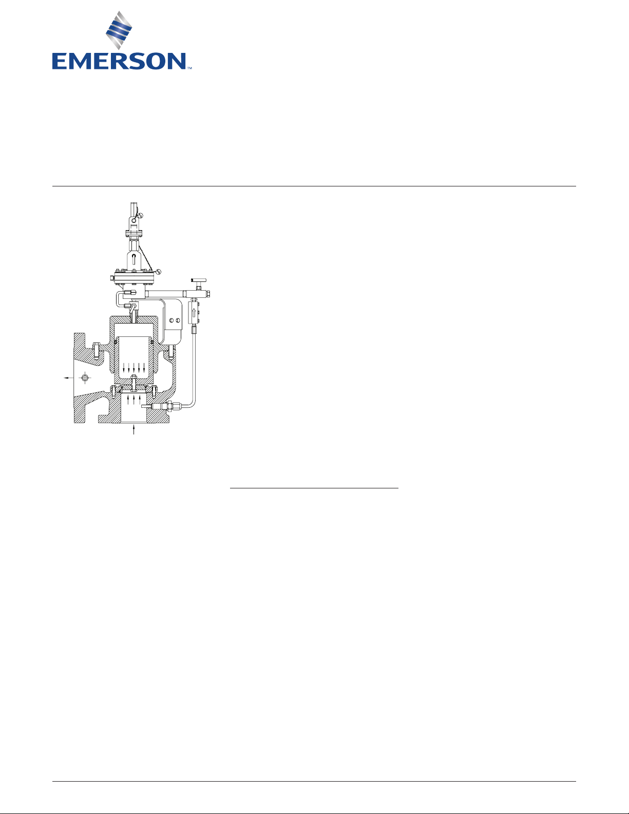
FIGURE 1
Pilot vent
Dome (top of the piston)
Pilot
Auxiliary setting device
Bonnet vent
Field test
Check
valve
1 GENERAL VALVE DESCRIPTION
Refer to Figure 1
The Anderson Greenwood Series 95 Valve
consists of a main valve and pilot. The main
valve has an unbalanced piston with O-ring
seat. Tank pressure is applied to the top of the
piston by means of the pilot. The area of the top
of the piston is larger than the bottom and the
valve remains closed.
When the tank pressure increases to the
set pressure of the pilot, the pilot opens and
vents the pressure from the top of the piston.
Theforce acting on the bottom of the piston is
now greater than that acting on the top and the
valve opens.
When the tank pressure decreases to the
closing pressure of the pilot, the pilot closes
and tank pressure is directed to the top of the
piston. The force acting on the top of the piston
is now greater than the force on the bottom and
the valve closes.
Outlet
O-ring seat
P (Tank)
P (Tank)
Inlet (tank pressure)
Tank pressure
sense line
Main valve
Unbalanced
piston
2
Page 3

ANDERSON GREENWOOD SERIES 95 PILOT OPERATED SAFETY RELIEF VALVES
InstallatIon and MaIntenance InstructIons
FIGURE 2
Item Description
1 Auxiliary setting device
2 Supply tubing
3 Pilot exhaust tubing
4 Pilot bracket bolt
5 * Pilot
6 Pipe nipple
7 Field test hand valve
8 Field test plug
9 Connector
10 Check valve
11 Connector
12 Connector
13 Close tee
15 Check valve
16 Connector
17 Connector
18 Pipe plug
19 Body bolt
20 Lock washer
21 Upper body
22 * Diaphragm
23 * Washer
24 Spring pin
25 Lower body
26 Body
27 Spring
28 Ball
29 O-ring
[1]
30
Gasket
Auxiliary setter, with field test and backflow preventer
Indexed in order of disassembly
2 ACCESSORY MAINTENANCE
Refer to Figure 2
The accessories used on the Series 95 are
the auxiliary setter, field test and backflow
preventer. The field test and backflow preventer
are always used; the auxiliary setter is optional.
Only the backflow preventer, which consists of
[2]
one
diaphragm type check valve and a ball
check valve requires maintenance. Normal
maintenance is to clean the check valves and
replace the diaphragm, washer, gasket
[1]
and
O-ring.
When replacing the diaphragm, care should
be taken not to damage the diaphragm. To
assemble the diaphragm type valve, uniformly
tighten the body bolts, first one side, then the
opposite side. Do not overtighten the bolts as this
will distort the diaphragm and cause leakage.
NOTES
1. Gasket used on some check valves. If check valve
has gasket, use gasket supplied in repair kit otherwise discard kit gasket.
2. Some earlier model valves use two diaphragm
check valves and no ball check valve.
* Recommended spare parts for repairs
3
Page 4

ANDERSON GREENWOOD SERIES 95 PILOT OPERATED SAFETY RELIEF VALVES
InstallatIon and MaIntenance InstructIons
FIGURE 3
Item Description
10 Lower bracket
20 Upper bracket
30 Bracket bolt
40 Washer
50 Hex nut
100 Body
110 Screw
140 Piston
150 Seat retainer
200 Washer (used on 6 x 8 only)
210 Cap/liner
420 Bolt
460 Nozzle
520 Nut
550 Washer
560 * Guide seal
610 * O-ring seat
620 * Cap gasket
630 * Nozzle gasket
640 * Washer
700 Cap bolt - hex
710 Cap bolt - eye
NOTES
1. Recommended spare parts for repairs
* Not shown - used on ≥ 4”
Refer to Section 8 for Soft goods repair kits part
numbers.
[1]
Indexed in order of disassembly
3 MAIN VALVE MAINTENANCE
Refer to Figure 3
Normal valve maintenance will be to only clean
the parts. It may also be necessary to replace
the seat. The piston seal should not need to be
replaced. If the piston seal is removed, a new
seal must be installed.
The piston can be removed from the cap/liner
by pulling the piston out or by pushing it out
with a rod through the hole in the top of the
cap/liner.
No lubricant is required on the piston seal.
A small amount of thread sealant should be
used on the pipe threads to prevent leakage.
PTFEtape is recommended.
The piston should be assembled to the cap/
liner and the two parts should then be
assembled to the valve body. The piston can
be prevented from sliding out of the cap/liner
during assembly by covering or plugging the
hole in the top of the cap/liner.
For marine service, the bolts in the main valve
and pilot exposed to the environment should
be replaced during routine maintenance every
five years.
4
Page 5

ANDERSON GREENWOOD SERIES 95 PILOT OPERATED SAFETY RELIEF VALVES
InstallatIon and MaIntenance InstructIons
4 PILOT MAINTENANCE
Refer to Figure 4A
Anderson Greenwood recommends the pilot
be returned to the factory for repair or to be
repaired by a factory serviceman in the field.
Normal maintenance is to completely
disassemble the pilot and replace all the
diaphragms, seals and seat. To facilitate
assembly, place all parts removed in an
orderly arrangement so that the correct
parts are assembled in the proper sequence.
Nolubricants are required in the pilot. A small
amount of thread sealant should be used on the
pipe threads to prevent leakage. PTFE tape is
recommended.
Assembly is done in the reverse order of the
disassembly. The following items should be
observed when assembling the pilot:
• The round metal diaphragm is the sense
diaphragm. The clear PTFE diaphragm is the
boost diaphragm.
• The holes in the spindle diaphragm must be
aligned with all the holes in the body. The
small hole in the lower case must be aligned
with the hole in the body.
• Two of the six case bolts must be assembled
through the holes in the lower case before
it is attached to the body. After attachment
there is insufficient clearance to do so.
• Tighten the spindle nut snugly but not
excessively. Three diaphragms are
sandwiched in the spindle/stack assembly
and excessive tightening will damage them.
Hold the hex spacer when torquing the
spindle nut to prevent the stack from rotating.
After the pilot is assembled the set pressure
must be adjusted. Refer to Section 5
forinstructions.
FOR FIGURES 4A AND 4B
Item Description
100 Body
110 Nozzle
120 Hex spacer
130 Boost spacer
140 Sense spacer
150 Sense plate
160 Boost plate
170 Spindle spacer
190, 190A Pressure adjuster lock nut
200, 200A Bonnet assembly
210 Upper diaphragm case
220 Lower diaphragm case
230 Spacer ring
235A Adapter
240 Case bolt
250 Lock washer
260 Hex nut
320 Boost tube
330 Connector elbow
340 Body bolt
350 Blowdown needle
370 Hex jam nut
380 Retainer plug
390 Blowdown bushing
400 Filter screen (not shown)
420 Retainer seat
430 Retainer ring
440A Hex nut
450 Bonnet insert
460 Wire (not shown)
470 Seal - ½” diameter (not shown)
[1]
[1]
Item Description
490 Washer shim (for stack height)
500 Spindle diaphragm*
510 Sense/boost diaphragm*
520 Sense diaphragm*
550 Spindle
555A Extension rod
560 Check plate
570 Seat
580, 580A Bonnet gasket*
610 Body bolt seal*
620 Blowdown seal*
630 Bushing seal*
640 Case gasket*
660 Spindle seal*
680 Spindle gasket*
690 Spindle diaphragm gasket*
730 Seat base - type 95
740 Ball
750 Hex nut
760, 760A Cap
770, 770A Bonnet bolt
780 Lock washer
790, 790A Pressure adjustment screw
800 Vent - body (not shown)
805A Vent - plug
810 Vent - connector
815 Vent - tube
820, 820A Spring washer
830, 830A Spring disc
840, 840A Spring
NOTES
A = used in auxiliary setter
* Recommended spare parts for repairs
1. Part of Item 200 assembly
Refer to Section 8 for Soft goods repair kits part
numbers.
Refer to Section 8 for Soft goods repair kits part
numbers.
5
Page 6

ANDERSON GREENWOOD SERIES 95 PILOT OPERATED SAFETY RELIEF VALVES
InstallatIon and MaIntenance InstructIons
FIGURE 4A
Series 95 pilot with auxiliary setter
6
Page 7

ANDERSON GREENWOOD SERIES 95 PILOT OPERATED SAFETY RELIEF VALVES
InstallatIon and MaIntenance InstructIons
FIGURE 4B
7
Page 8

ANDERSON GREENWOOD SERIES 95 PILOT OPERATED SAFETY RELIEF VALVES
InstallatIon and MaIntenance InstructIons
5 PILOT SET PRESSURE ADJUSTMENT
Refer to Figure 5
To adjust the opening and closing pressure of
the pilot after the pilot has been completely
disassembled and reassembled, a test set-up
similar to that shown in Figure 5 should be used.
5.1 Check the position of the blowdown
adjustment screw. It should be turned half
way in (approximately 5 turns).
5.2 With the pressure adjustment screw turned
most of the way in, increase the supply
pressure to the desired set pressure.
Backthe pressure adjustment screw out
until the pilot “snaps” open. The dome
pressure should decrease to 25% or less
of the supply pressure. When the pilot
opens and flows, the supply pressure will
decrease due to the pressure drop in the
lines to the accumulator. The set pressure
is the highest pressure recorded on the
supply pressure gauge.
5.3 Decrease the supply pressure to the
correct reseat pressure and back the
blowdown adjustment screw out until the
dome pressure “snaps” back. The supply
pressure at which this occurs is the reseat
pressure and it should be about 90% of
the set pressure. When the pilot reseats,
the supply pressure will increase due to
reduced flow through the supply line. The
reseat pressure will be the lowest pressure
read on the supply gauge. Tighten the
jam nut after each setting for accurate
readings. Recycle the pilot valve to verify
the settings. A small interaction between
the blowdown adjustment and the pressure
adjustment will occur.
Auxiliary set pressure
adjustment under cap
Supply pressure
Vent
Accumulator (¼ cubic ft.)
Supply
Supply port
½” (1.5 mm) pipe
Primary set pressure
adjustment under cap
Blowdown
adjustment
½” (1.5 mm) pipe
6” to 12” long
FIGURE 5
Series 95 pilot test set-up
Dome pressure
gauge
8
Page 9

ANDERSON GREENWOOD SERIES 95 PILOT OPERATED SAFETY RELIEF VALVES
InstallatIon and MaIntenance InstructIons
6 PILOT SET PRESSURE FIELD TEST
PROCEDURE
Refer to Figure 6
This procedure is for measuring the pressure
where the valve will open. It will not measure
where the valve closes. To measure the closing
pressure, use the procedure in Section 5.
6.1 Remove the pilot discharge tube from the
pilot and replace with a cap that has a
.06”diameter (1.5 mm) hole in it.
6.2 Connect the test equipment to the field test
valve.
6.3 With the metering and vent valve closed,
open the gas bottle and adjust the regulator
pressure to about 200 psi (14 kp/cm
2
).
6.4 Open the field test valve. Slowly open the
metering valve and observe the test gauge.
Increase the pressure until gas flow at the
pilot discharge fitting increases rapidly.
The pressure at which this occurs is the set
pressure of the valve.
6.5 To adjust the opening pressure turn
the spring adjusting screw under the
cap/adapter “in” to increase pressure or
“out” to decrease pressure.
6.6
The IMO (International Maritime Organization)
Rule set pressure tolerances are:
+ 10% 0 - 21.3 psi (0 - 1.5 kp/cm
+ 6% 21.3 - 42.7 psi (1.5 - 3.0 kp/cm
+ 3% 42.7 psi or 3.0 kp/cm
Auxiliary set pressure
adjustment under cap
2
)
2
and above
2
)
Auxiliary setter
Unscrew here for removal
(install hand-tight only lubricate threads)
Pilot discharge fitting
Pilot discharge tube
Main valve
Primary set pressure
adjustment under cap
Bonnet vent
Pilot
Field test
valve
Test gauge
Metering valve
High
pressure
Vent valve
Adapter fitting to ½” NPT port
on field test valve
hose
FIGURE 6
Series 95 pilot recommended field test
Nitrogen
bottle with
shutoff valve
and regulator
set-up
9
Page 10

ANDERSON GREENWOOD SERIES 95 PILOT OPERATED SAFETY RELIEF VALVES
InstallatIon and MaIntenance InstructIons
7 VALVE DIAGNOSIS GUIDE
Problem Causes
Valve does not close on start-up with
littleor nocargo tank pressure
Valve opens at a pressure below
nameplateset pressure
Valve opens at correct pressure but
doesnot close
(Refer to Figure 1)
Main valve piston in lift position, pressurize domethrough
Fieldtest handvalve (0.5 to 1.0 kp/cm2) to close piston.
Set pressure incorrect
Auxiliary setter device incorrect one for valve.
Auxiliary setter device not screwed down all the way.
Pilot sense diaphragm leaks. Check for gas flow
throughpilot spring bonnet vent.
Backflow preventer check valve leaks. (Item 15, Figure2)
Checkfor gas flow at discharge tube to main valve outlet.
Nogas flow should be detected.
Pilot not sensing correct tank pressure
Check valve in tank pressure sense line (Figure 1) restricted.
Filter screen in pilot or small orifices in pilot restricted.
IMPORTANT
In an emergency, main valve can be closed by pressurizing dome
(top of piston) through close tee (Item 13, Figure 2) remove plug
(item 18) and apply pressure equal to tank pressure.
8 REPAIR KITS
Main valve size Soft goods kit part number Bolt kit part number
2 x 3 04.4744.810 04.4744.330
3 x 4 04.4744.804 04.4744.331
4 x 6 04.4744.834 04.4744.332
6 x 8 04.4744.835 04.4744.333
Pilot 04.4744.025 04.4744.333
Backflow preventer (diaphragm) 04.4744.781 04.4744.335
Check valve (ball check) 04.4744.782 None
© 2017 Emerson. All rights reserved.
10
 Loading...