

Page 1

Quick Start Guide
MHM-97390, Rev 1
December 2018
AMS 2140 Machinery Health™ Analyzer
Advanced Laser Alignment Application
Quick Start Guide
Page 2

Copyright
©
2018 by Emerson. All rights reserved.
No part of this publication may be reproduced, transmitted, transcribed, stored in a retrieval
system, or translated into any language in any form by any means without the written permission
of Emerson.
Disclaimer
This manual is provided for informational purposes. EMERSON MAKES NO WARRANTY OF ANY
KIND WITH REGARD TO THIS MATERIAL, INCLUDING, BUT NOT LIMITED TO, THE IMPLIED
WARRANTIES OF MERCHANTABILITY AND FITNESS FOR A PARTICULAR PURPOSE. Emerson shall
not be liable for errors, omissions, or inconsistencies that may be contained herein or for
incidental or consequential damages in connection with the furnishing, performance, or use of
this material. Information in this document is subject to change without notice and does not
represent a commitment on the part of Emerson. The information in this manual is not allinclusive and cannot cover all unique situations.
Patents
The product(s) described in this manual are covered under existing and pending patents.
Contents
Introduction ................................................. 3
Laser and sensor setup
..................................8
Job setup .................................................... 16
Perform horizontal alignment .....................22
Transfer alignment job data and
tolerances ...................................................33
Print alignment summary reports ............... 36
Verify the AMS Machinery Manager
version ........................................................38
sensALIGN approvals .................................. 39
Quick Start Guide December 2018
2 AMS 2140 Advanced Laser Alignment Application
Page 3

1 Introduction
1.1 Basic and Advanced Laser Alignment Application
overview
The AMS 2140 Basic and Advanced Laser Alignment Applications enable you
to perform horizontal machine alignment. In addition, the Advanced Laser
Alignment Application adds advanced options for horizontal alignment along
with new applications for vertical machines and straightness measurements.
The Basic Laser Alignment Application is similar to the Basic mode available in
the Advanced Laser Alignment Application. Alignment is done with the help
of the sensALIGN® laser and sensor (Emerson P/N A8240).
The horizontal alignment feature is used to acquire and display alignment
data for machines where the machine moves are done at the machine feet.
Horizontal alignment is available in Basic and Advanced mode. In Basic mode,
you have access to only a subset of the full functionality of a horizontal
alignment job. In Advanced mode, you have access to the full functionality of
a horizontal alignment job. The controls for enabling thermal growth input,
foot pre-check, review results, live move orientation, live move alerts, setting
the alignment method, and changing the placement of the laser and sensor
are available only in Advanced mode.
Except for differences in the alignment job parameters you can set under the
Laser Align Application ALT screen, the procedure for performing Basic
horizontal alignment is identical to Advanced horizontal alignment.
You can create alignment jobs and transfer them to AMS Suite: Machinery
Health Manager for storage and analysis.
This document only covers horizontal alignment using the Advanced Laser
Alignment Application. For a complete list of the Advanced Laser Alignment
Application functionality, refer to the Alignment chapter of the AMS 2140
Machinery Health Analyzer User Guide.
December 2018 Quick Start Guide
Quick Start Guide 3
Page 4
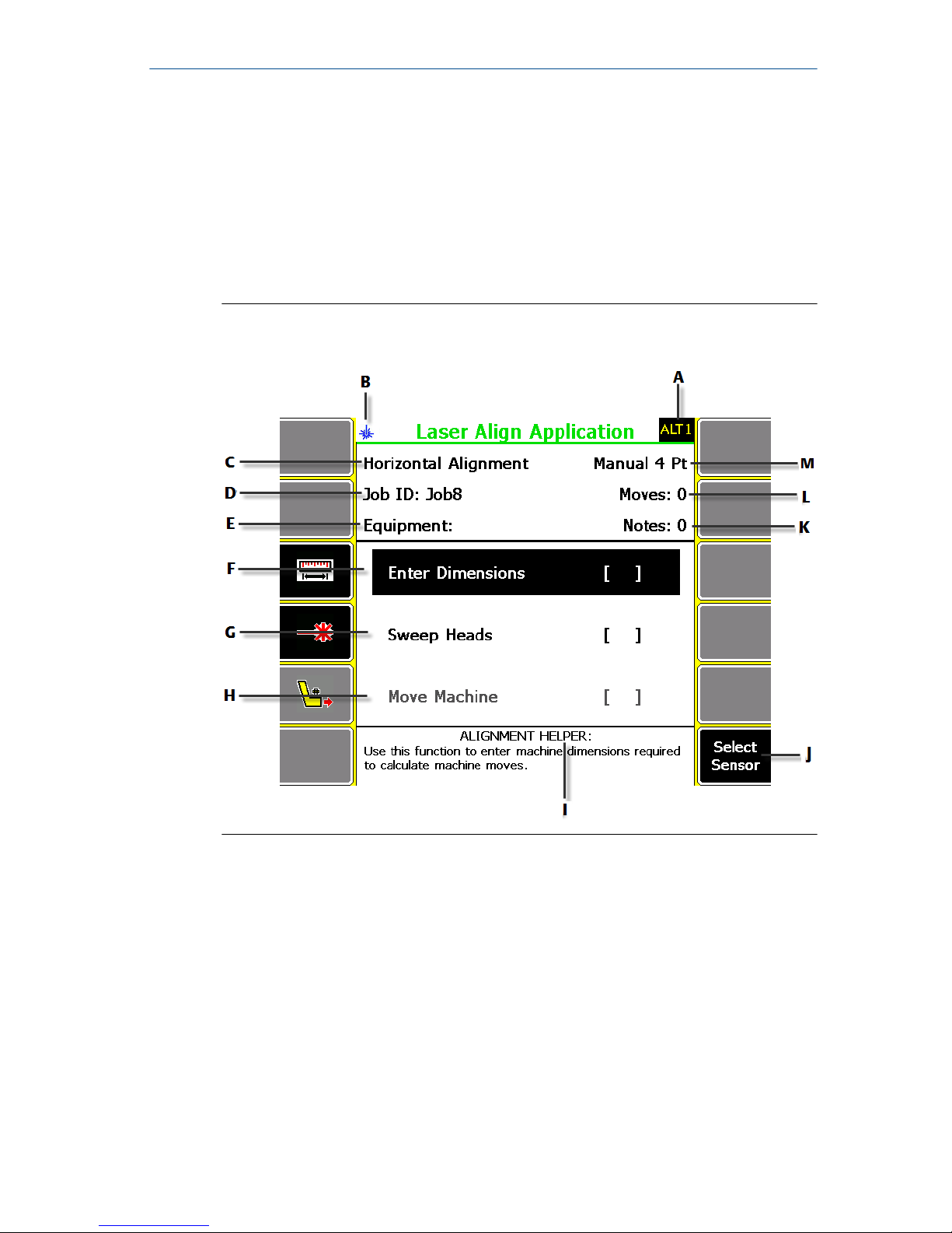
1.2 Laser Align Application main menu
From the AMS 2140 Home screen, press F10 Adv. Laser Align to open the Laser
Align Application main menu.
Horizontal alignment is a three-step process. The Laser Align Application
main menu lets you monitor the progress of an alignment job. An X marks a
completed step.
Laser Align Application main menu—Advanced horizontal
alignment job
Figure 1-1:
A. An alternate (ALT) screen includes additional options.
B. Icon indicating that this is a Bluetooth-only application.
C. The alignment mode (horizontal, vertical, or straightness).
D. The identifier for the job.
E. The identifier for the equipment.
F. Enter machine dimensions for the machines being aligned.
G. Acquire sweep data required to determine the alignment condition of the machines.
H. View machine moves required to bring the machines into alignment.
I. View helpful information regarding the highlighted step or the active screen.
You can also view additional helpful information about the active screen by pressing the Help button
twice.
J. Choose which Bluetooth sensor to communicate with.
Quick Start Guide December 2018
4 AMS 2140 Advanced Laser Alignment Application
Page 5

K. The number of notes assigned to the job.
L. The number of data acquisitions for the job.
M. The alignment method for the job.
ALT1 keys
Option Description
F1 Intentionally blank.
F2 Intentionally blank.
F3 Enter machine dimensions for the machines being aligned. See Section 4.1 for
more information.
If thermal growth is enabled, enter thermal growth information. This is
available only in Advanced mode.
F4 Acquire alignment data using the alignment method defined for the job. See
Section 4.2 for more information.
If the foot pre-check option is enabled, check for soft foot. This is available
only in Advanced mode.
F5 View machine moves required to bring the machines into alignment.
If an alignment correction is necessary and requires a live move, do the
adjustment from this step.
See Section 4.3 for more information.
F6 Intentionally blank.
F7 Intentionally blank.
F8 Intentionally blank.
F9 Intentionally blank.
F10 Intentionally blank.
F11 Intentionally blank.
F12 Select
Sensor
Choose which Bluetooth sensor to communicate with.
The list is populated with Bluetooth devices already paired with the AMS
2140.
December 2018 Quick Start Guide
Quick Start Guide 5
Page 6
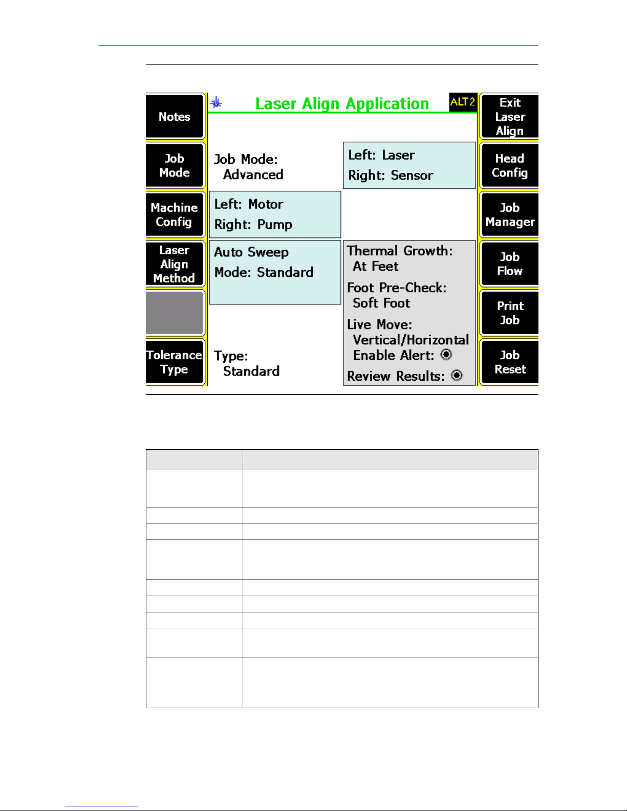
ALT 2 keys—Advanced horizontal alignment jobFigure 1-2:
ALT 2 keys—horizontal alignment
Option Description
F1 Notes Create, add, or remove notes from an alignment job or the AMS 2140.
Notes can be saved with the job to help you remember important
information about a machine.
F2 Job Mode Select Advanced or Basic.
F3 Machine Config Select the machine components for the alignment job.
F4 Laser Align
Method
Select the alignment method.
This is intentionally blank when the job mode is set to Basic. Manual 4
Point is the only alignment method available in Basic mode.
F5 Intentionally blank.
F6 Tolerance Type Select Standard or Jackshaft tolerance.
F7 Exit Laser Align Exit the Laser Align Application and return to the Home screen.
F8 Head Config Specify or view the placement of the laser and sensor.
This is also where you can check the status of the laser and sensor.
F9 Job Manager Perform job-related tasks such as creating, activating, copying, or
editing a job.
This is also where you can select the Connect for Transfer button that
enables you to transfer jobs between the AMS 2140 and the PC.
Quick Start Guide December 2018
6 AMS 2140 Advanced Laser Alignment Application
Page 7

Option Description
F10 Job Flow Select optional parameters to include as part of the current alignment
job. This is available only in Advanced mode.
Parameters include thermal growth, foot pre-check, live move
orientation, live move alerts, and an option to review alignment results.
Refer to the Alignment chapter of the AMS 2140 Machinery Health
Analyzer User Guide for more information on thermal growth, foot precheck, and reviewing of alignment results.
F11 Print Job Print a summary report of the alignment job to AMS Machinery Manager
or to a memory card inserted into the AMS 2140.
F12 Job Reset Reset the job data by clearing all stored data, loading default values, or
by loading default tolerance values.
December 2018 Quick Start Guide
Quick Start Guide 7
Page 8
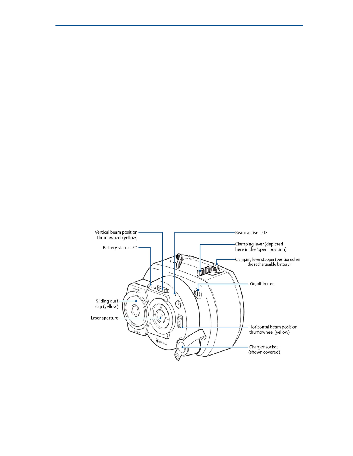
2 Laser and sensor setup
1. Mount the brackets on opposite sides of the coupling.
2.
Mount the laser and sensor on the brackets.
3. Adjust the laser beam so that it is correctly centered on the sensor.
4. Enable Bluetooth in the AMS 2140.
5. Pair the sensor.
These steps are covered in detail in the topics that follow.
2.1 Laser and sensor overview
The laser and sensor communicate via Bluetooth with the AMS 2140.
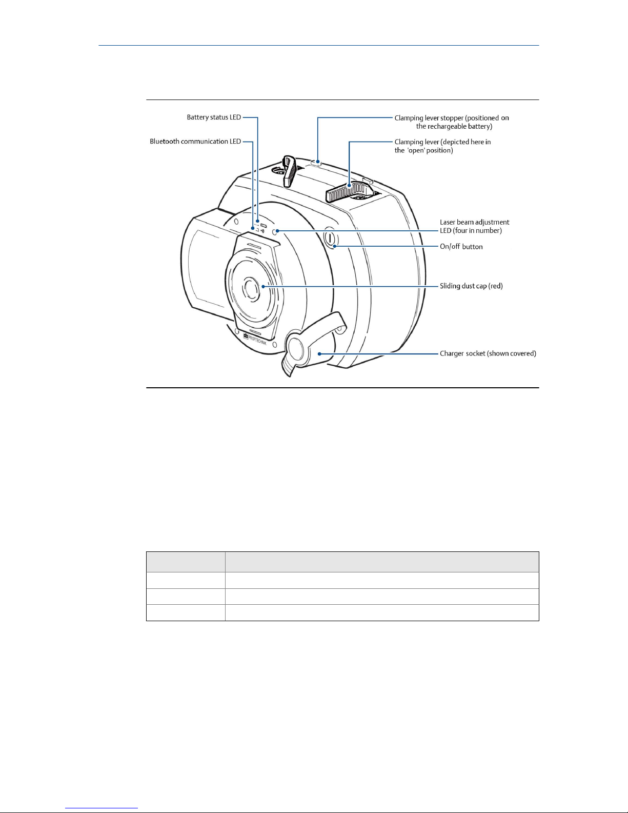
The laser and sensor have a similar appearance and are differentiated by the
color of their sliding dust caps—yellow for the laser and red for the sensor. To
power on the laser and sensor, briefly press and hold the on/off button.
The laser
The laser beam is adjusted during set-up by changing its vertical and
horizontal angles using the position thumbwheels, so that the beam strikes
the sensor lens perpendicular to the lens surface.
The laser is water and dust resistant (IP 65). The internal optics and
electronics are internally sealed, preventing possible contamination.
Quick Start Guide December 2018
8 AMS 2140 Advanced Laser Alignment Application
Page 9
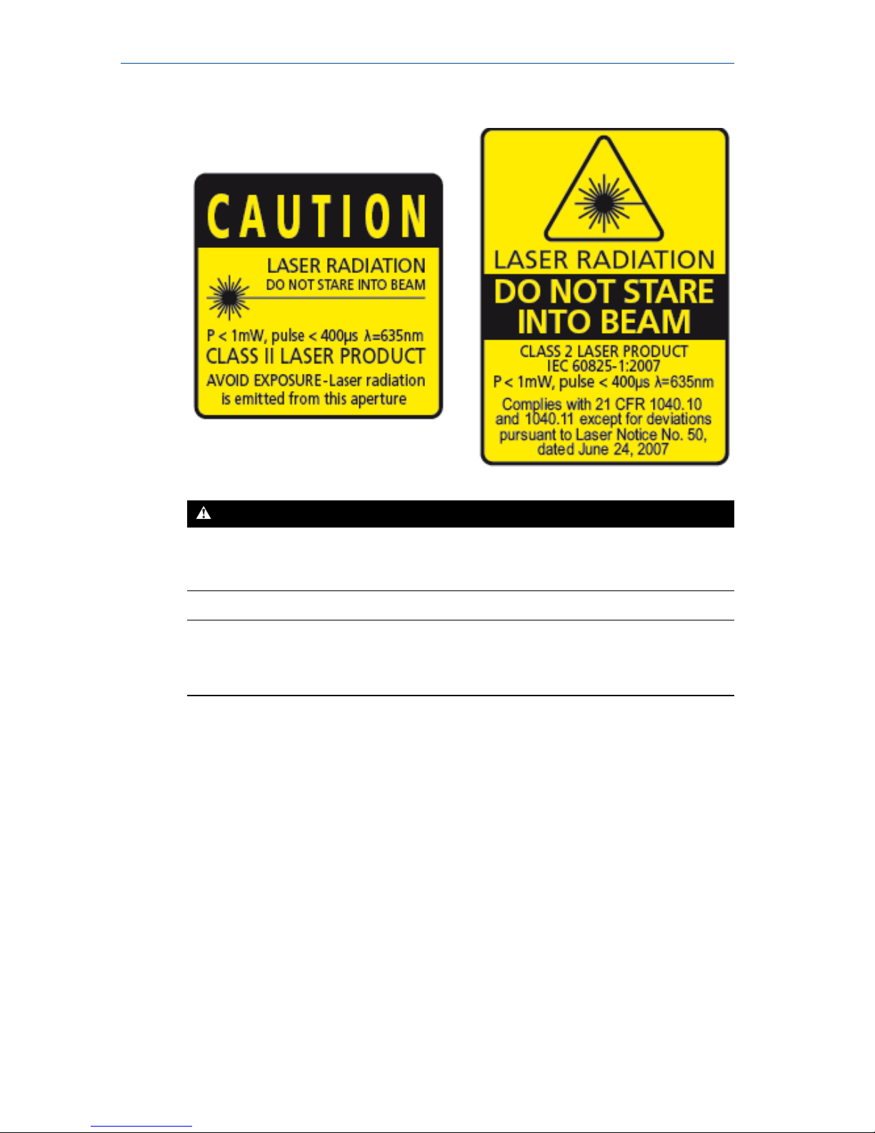
Laser safety
WARNING!
• Do not look directly into the laser beam at any time.
• Do not insert any optical devices into the beam path.
Note
The red LED on the front of the laser illuminates whenever the laser beam is
emitted.
December 2018 Quick Start Guide
Quick Start Guide 9
Page 10
The sensor
The sensor contains two position detectors that measure the exact position
and inclination of the laser beam as the shafts are rotated.
Bluetooth radio is integrated into the sensor for wireless transmission of
measurement data to the AMS 2140.
Terminology
The following terminologies are used throughout this document.
Term Meaning
Laser Refers to the laser head (yellow dust cap)
Sensor Refers to the sensor head (red dust cap)
Laser fixtures Refers to both the laser and sensor heads
2.2 Mount the brackets
Mount the brackets on opposite sides of the coupling on either the shafts or
on the solid coupling hubs, and both at the same rotational position.
Quick Start Guide December 2018
10 AMS 2140 Advanced Laser Alignment Application
Page 11
Prerequisites
To obtain the highest possible measurement accuracy and to avoid damage
to equipment:
• Ensure the brackets fit solidly onto their mounting surfaces.
• Do not use self-constructed mounting brackets, or modify the original
bracket configuration. For example, do not use support posts longer than
those supplied with the bracket.
• Choose the shortest support posts that will allow the laser beam to pass
over or through the coupling.
Note
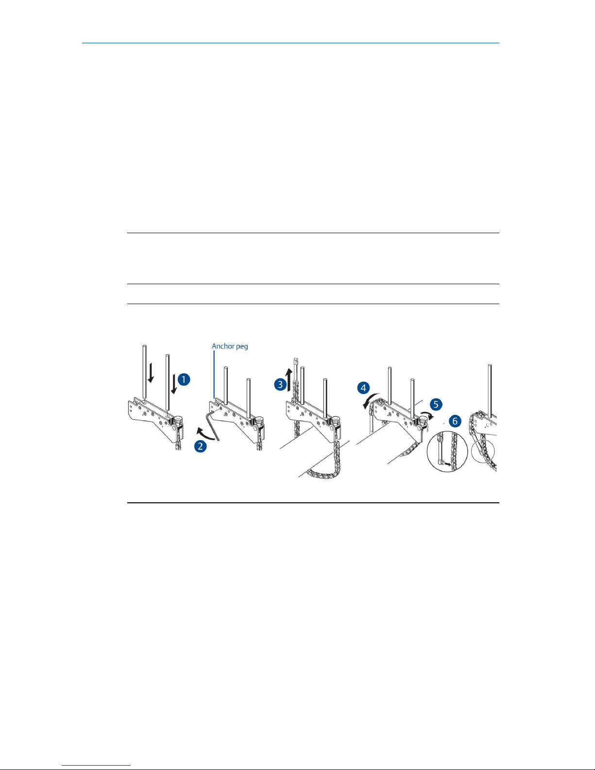
Refer to Figure 2-1 for detailed illustrations on how to mount the brackets.
The numbers in the figure correspond to the numbers in the following steps.
Mount the bracketsFigure 2-1:
Procedure
1. Insert the support posts into the bracket.
2. Fasten the support posts in place by tightening the hex screws on the
sides of the bracket frame.
3. Place the bracket on the shaft or coupling, wrap the chain around the
shaft and feed it through the other side of the bracket. If the shaft is
smaller than the width of the bracket frame, insert the chain from the
inside of the bracket. If the shaft is larger than the bracket width, insert
the chain into the frame from the outside.
4. Catch the chain loosely on the anchor peg.
5. Turn the bracket thumbscrew clockwise to tighten the assembly onto the
shaft.
December 2018 Quick Start Guide
Quick Start Guide 11
Page 12
6. Clip the loose end of the chain back onto itself.
The bracket should now be tight upon the shaft. Do not push or pull on
the bracket to check because this could loosen its mounting.
To remove the brackets, turn the thumbscrew counter-clockwise, and
then remove the chain from its anchor peg.
Note
The compact chain-type brackets cover most situations, but in cramped or
special cases, other types of brackets may be required.
2.3 Mount the laser and sensor
Mount the laser on the support posts of the bracket fixed on the shaft of the
left machine (usually the reference machine), and the sensor on the support
posts of the bracket fixed on the shaft of the right machine (usually the
moveable machine)—as viewed from a normal working position.
Procedure
1.
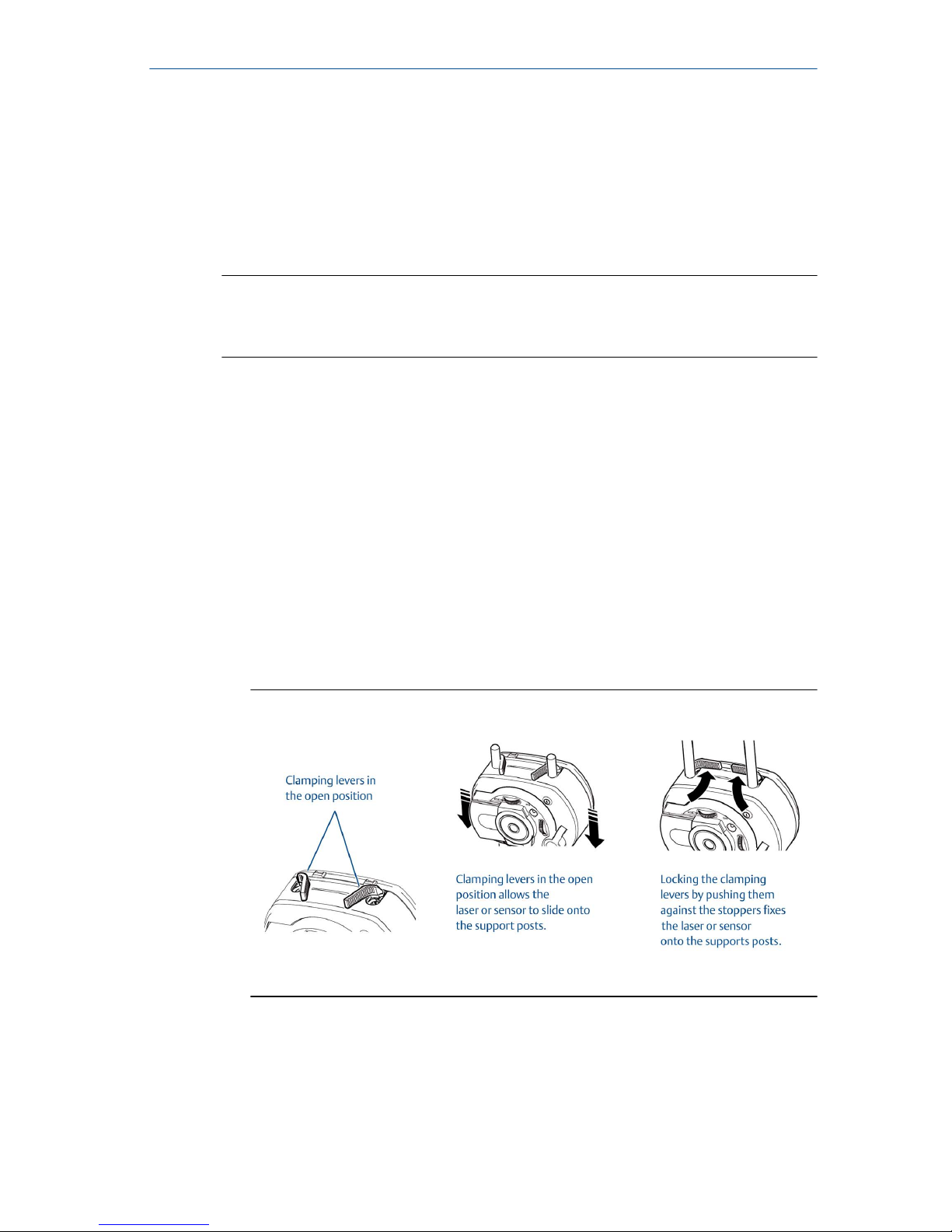
Before mounting the laser and sensor, ensure that the yellow clamping
levers are in the open position by pointing them to the front of the laser
and sensor as shown in Figure 2-2. This enables the laser and sensor to
slide onto the support posts.
Clamping leversFigure 2-2:
2. Fix both the laser and sensor onto the respective support posts by locking
the yellow clamping levers. Lock the levers by pushing them backwards
until they rest on the stoppers. Ensure the laser beam can pass over or
through the coupling and is not blocked.
Quick Start Guide December 2018
12 AMS 2140 Advanced Laser Alignment Application
Page 13
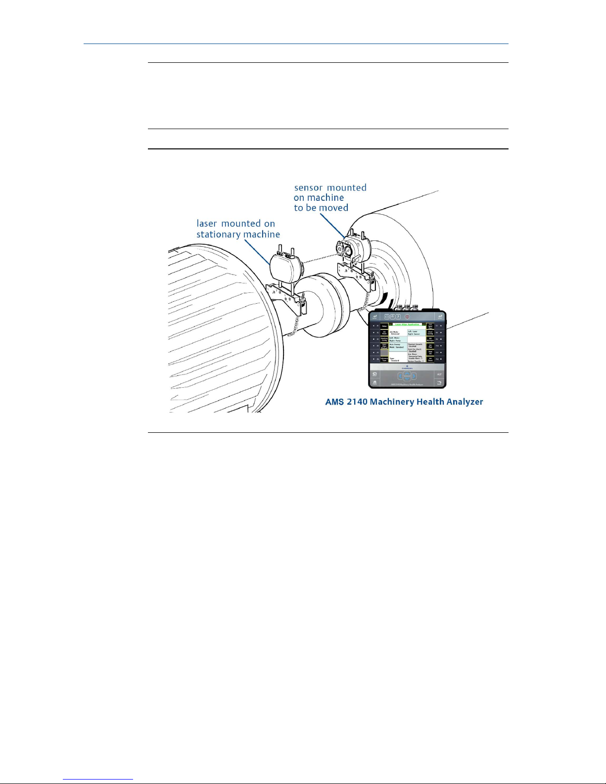
Note
Both the laser and sensor should be at the same height, as low as
possible, yet just high enough for the beam to clear the coupling flange.
They should also visually appear to be rotationally aligned to each other.
Horizontal alignmentFigure 2-3:
3. Make final adjustments, loosening the brackets slightly if necessary, then
rotating them and re-tightening.
2.4 Adjust the laser beam
1. Turn on the laser and sensor.
2. With the sensor lens covered, let the laser beam strike the center of the
sensor dust cap.
3. Slide the sensor dust cap to open the lens.
4. Observe the four laser beam adjustment LEDs on the sensor while
adjusting the laser beam using the vertical and horizontal beam
positioning thumbwheels on the laser.
Use the thumbwheels to adjust the horizontal and vertical laser beam
angles.
5. Continue with the adjustment until all four laser beam adjustment LEDs
on the sensor are blinking green once every second.
December 2018 Quick Start Guide
Quick Start Guide 13
Page 14

a. If the laser beam adjustment LEDs on the sensor are blinking green
twice every second, the angle at which the laser beam enters the
sensor is correct, but an offset is present. Eliminate the offset by
sliding back the sensor dust cap to cover the lens, then loosen the
chain type bracket supporting sensor, and move the sensor sideways.
At the same time, release the sensor clamping levers and move the
sensor upwards and downwards until the laser beam is centered on
the dust cap.
CAUTION!
During this adjustment, do not touch the laser.
b. Slide the sensor dust cap to open the lens and check the blinking of
the four laser beam adjustment LEDs. If all four are blinking green
once every second, then the laser beam is correctly centered on the
sensor.
Refer to the Alignment chapter of the AMS 2140 Machinery Health
Analyzer User Guide for more information on the laser beam
adjustment LED lights and their meanings.
2.5 Enable Bluetooth radio in the AMS 2140
1. Press Home > F5 Comm Setup > F7 Bluetooth Setup.
2.
Press F2 Bluetooth to enable the Bluetooth radio.
When the radio is enabled, the
icon appears in the upper corner of
the screen.
2.6 Pair the sensor
For the laser fixtures to communicate with the AMS 2140, you must first pair
the sensor. Bluetooth radio is integrated into the sensor.
Prerequisites
• Ensure the sensor is close to the AMS 2140 (within 30 feet) and is turned
on.
• Enable the Bluetooth radio in your AMS 2140.
Procedure
1.
Press Home > F5 Comm Setup > F7 Bluetooth Setup.
Quick Start Guide December 2018
14 AMS 2140 Advanced Laser Alignment Application
Page 15

2. If more than one device is listed, use the up or down arrow keys to select
the sensor.
3.
Press F7 Pair to pair the sensor.
December 2018 Quick Start Guide
Quick Start Guide 15
Page 16

3 Job setup
You need an alignment job to store alignment data.
1.
Create an alignment job.
2. Activate an alignment job.
3. Set the job parameters.
These steps are covered in detail in the topics that follow.
3.1 Create an alignment job
1. From the Laser Align Application main menu, press ALT > F9 Job Manager.
The Job Manager screen is displayed.
2. Press F1 Create New Job.
Optionally, you can enter more information about the job.
Option Description
F2 Edit Job ID Enter a unique ID to identify the job and press Enter.
F3 Edit Equip ID Enter the equipment ID to identify the machines being aligned and press
Enter.
F4 Edit Equip
Desc
Enter an equipment description to add additional information on the
machines being aligned and press Enter.
F5 Edit Area Enter an area description to identify the location of the machines being
aligned and press Enter.
F6 Edit Coupling
Number
Enter the coupling number and press Enter.
This option is useful when there is more than one coupling on the
machines being aligned.
F7 Set Mode Choose Horizontal as the alignment mode and press Enter.
F8 Edit User ID Enter the initials of the user performing the alignment job and press
Enter.
3. Press Enter.
You can save the alignment job for later or activate it to be able to store
alignment data.
4.
Press F9 Activate Job to activate the job you created.
3.2 Activate an alignment job
You need to activate an alignment job to store data to the job.
Quick Start Guide December 2018
16 AMS 2140 Advanced Laser Alignment Application
Page 17

Procedure
1.
From the Laser Align Application main menu, press ALT > F9 Job Manager.
The Job Manager screen is displayed.
2. Press F10 or F11 to select the job you want to activate and press F9 Activate
Job.
The Laser Align Application main menu is then displayed. It is where you
can begin the three-step alignment process and store data in the active
alignment job.
3.3 Set the job parameters
This document only covers some of the job parameters you can set up for a
horizontal alignment job. Refer to the Alignment chapter of the AMS 2140
Machinery Health Analyzer User Guide for more information on the other job
parameters you can set.
3.3.1 Set the job mode
Horizontal alignment is available in Basic and Advanced mode.
Procedure
1. Activate or create a horizontal alignment job.
For newly created jobs, the job mode is set to Advanced by default.
2. From the Laser Align Application main menu, press ALT > F2 Job Mode.
Pressing this key toggles between Advanced and Basic modes.
3. Press Yes to proceed with the job mode change.
CAUTION!
Changing the job mode clears all data previously acquired for the job.
3.3.2 Change the machine configuration
Change the machine configuration on the AMS 2140 to reflect your current
machine setup.
Procedure
1. Activate a horizontal alignment job.
2. From the Laser Align Application main menu, press ALT > F3 Machine
Config.
December 2018 Quick Start Guide
Quick Start Guide 17
Page 18

3. Use the touchscreen or keypad to select an entry from the Machine Type
list describing the left machine and press F5 Select Left Machine.
4.
Use the touchscreen or keypad to select an entry from the Machine Type
list describing the right machine and press F11 Select Right Machine.
5. Optionally, press F8 Change Machine View to change the machine view from
2D to an isometric machine view.
6. Press Enter.
3.3.3 Set the alignment method
Selecting an alignment method is available only in Advanced mode. In Basic
mode, Manual 4 Point is the only available alignment method.
Procedure
1. Activate a horizontal alignment job.
2. From the Laser Align Application main menu, press ALT > F4 Laser Align
Method.
3. Select an alignment method.
The Basic Laser Alignment Application defaults to Manual 4 Point. The
Advanced Laser Alignment Application lets you select from 5 different
methods.
This document only covers Auto Sweep and Manual 4 Point. Refer to the
Alignment chapter of the AMS 2140 Machinery Health Analyzer User
Guide for more information on the other available alignment methods.
a. For Auto Sweep, also select Standard or Averaging as the mode of
operation.
b. For Manual 4 Point, also enter a sample rate.
The sample rate sets the number of samples (1 to 25) to be averaged
to generate a single reading.
4. Press Enter.
3.3.4 Change the laser and sensor placement
Change the laser and sensor placement on the AMS 2140 to reflect your
current laser and sensor setup.
Changing the placement of the laser and sensor is available only in Advanced
mode.
Procedure
1. Activate a horizontal alignment job.
2. From the Laser Align Application main menu, press ALT > F8 Head Config.
Quick Start Guide December 2018
18 AMS 2140 Advanced Laser Alignment Application
Page 19

3. Press F2 Toggle Head Config to select where to position the laser and sensor
(left or right).
4.
Press Enter.
3.3.5 Set the tolerance type
Procedure
1. Activate a horizontal alignment job.
2. From the Laser Align Application main menu, press ALT > F6 Tolerance
Type.
The tolerance type changes between Jackshaft and Standard.
Standard tolerance is a combination of offset and angle tolerances. This
tolerance type is a direct indication of the alignment condition. Optimum
alignment occurs when offset and angular misalignments are zero.
Jackshaft tolerance measures the two angles between the shafts.
Optimum alignment occurs when angular misalignment is zero.
Standard tolerance is typically used on short spans where a single
coupling is present. Jackshaft tolerance is typically used on longer spans
where a jackshaft (or spool-piece) coupling is present.
3.3.6 Enable thermal growth option
Enabling the thermal growth option is available only in Advanced mode.
Procedure
1. Activate a horizontal alignment job.
2. From the Laser Align Application main menu, press ALT > F10 Job Flow > F8
Thermal Growth.
3. Select a thermal growth conversion option and press Enter.
Refer to the Alignment chapter of the AMS 2140 Machinery Health
Analyzer User Guide for more information on thermal growth, the
available thermal growth conversion options, and on entering thermal
growth values.
3.3.7 Enable foot pre-check
Checking for soft foot is available only in Advanced mode.
Procedure
1. Activate a horizontal alignment job.
December 2018 Quick Start Guide
Quick Start Guide 19
Page 20

2. From the Laser Align Application main menu, press ALT > F10 Job Flow > F9
Foot Pre-Check.
3.
Use the up or down arrow keys to select a foot pre-check method to apply
to the job and press Enter.
Refer to the Alignment chapter of the AMS 2140 Machinery Health
Analyzer User Guide for more information on foot pre-check.
3.3.8 Select live move orientation
This option enables you to perform a live move in the orientation you
selected. By default, live move is enabled in the horizontal direction.
Selecting a live move orientation is available only in Advanced mode.
Procedure
1. Activate a horizontal alignment job.
2. From the Laser Align Application main menu, press ALT > F10 Job Flow.
3. Press F10 Live Move to select from Horizontal Only or Vertical and Horizontal.
The selection for Live Move defaults to Horizontal Only, which is
recommended for most alignments. For special applications, you can
switch to Vertical and Horizontal.
Selecting Horizontal Only displays the movement required to align the
machines horizontally.
Selecting Vertical and Horizontal displays the movement required to align
the machines in the vertical and horizontal direction.
Only horizontal live moves are covered in this document.
See Section 4.3.1 for more information on performing a live move of the
machine.
3.3.9 Enable live move alerts
Enabling live move alerts is available only in Advanced mode.
When this option is enabled, the status LED on the AMS 2140 flashes and an
audible tone is generated when the machine alignment condition reaches
the target tolerance values. Increasing and decreasing flashes indicate when
the machine alignment crosses through the acceptable and excellent
tolerance condition thresholds. The number of flashes and flash rate are
consistent with the audible tone generated when the machine alignment
condition reaches the target tolerance values.
Quick Start Guide December 2018
20 AMS 2140 Advanced Laser Alignment Application
Page 21

Prerequisites
Enable the Status Beeper option on the General Setup screen to hear the
audible alerts. Press Home > ALT > F2 General Setup > F3 Set Status Beeper.
Procedure
1.
Activate a horizontal alignment job.
2. From the Laser Align Application main menu, press ALT > F10 Job Flow.
3. Press F11 Enable Alert to enable live move alerts.
A selected button means the alert is enabled.
December 2018 Quick Start Guide
Quick Start Guide 21
Page 22
4 Perform horizontal alignment
Horizontal alignment is a three-step process:
1.
Enter machine dimensions (Enter Dimensions).
2. Rotate the laser and sensor to acquire alignment data (Sweep Heads).
3. Review the required vertical and horizontal machine moves and align the
machine (Move Machine).
These steps are covered in detail in the topics that follow.
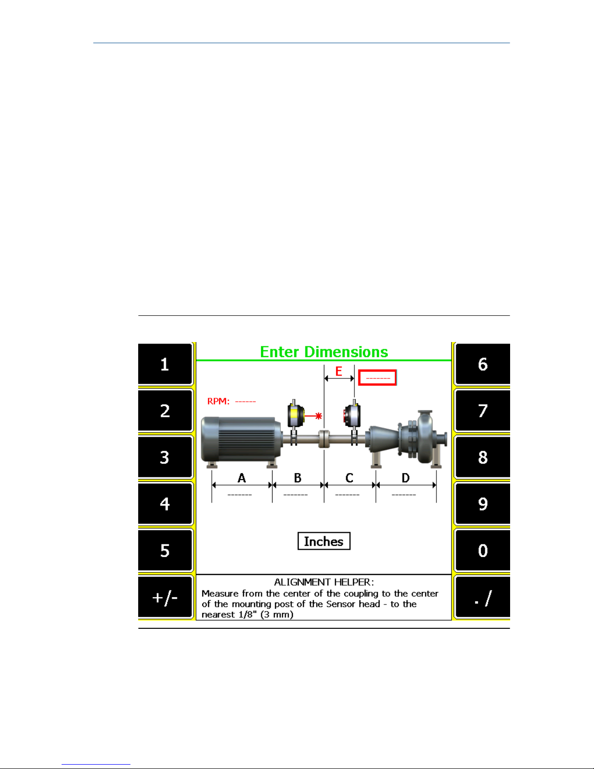
4.1 Enter machine dimensions
This is the first step in performing horizontal alignment. After completing this
step, the Enter Dimensions function on the Laser Align Application main
menu is marked with an X.
Enter dimensionsFigure 4-1:
Prerequisites
1. Ensure the laser and sensor are mounted on the machines.
2. Create and/or activate an alignment job and set up the job parameters.
An alignment job is needed to perform alignment.
Quick Start Guide December 2018
22 AMS 2140 Advanced Laser Alignment Application
Page 23

Procedure
1.
From the Laser Align Application main menu, press F3 Enter Dimensions.
2. Set the machine RPM.
This parameter is used to establish alignment tolerances. If you have a
variable speed machine, enter the highest RPM at which the coupling
operates.
3. Enter machine dimensions and press Enter.
Dimension* Measurement description
A Inboard foot to the outboard foot of the machine on the left
B Inboard foot of the machine on the left to the center of the coupling
C Center of the coupling to the inboard foot of the machine on the right
D Inboard foot to the outboard foot of the machine on the right
E Center of the coupling to the center of the sensor mounting post
F
Center of the coupling to the other center of the coupling
Note
The F dimension is only required when the tolerance type
is Jackshaft. This dimension is not needed when the
tolerance type is Standard.
*Measure to the nearest 1/8 inch (3 mm).
If the left machine is fixed, then the A and B dimensions are not required
and are not displayed.
If the right machine is fixed, then the C and D dimensions are not required
and are not displayed.
Note
All machine dimensions must be entered before advancing to the
thermal growth screens.
4. Enter thermal growth values if thermal growth is enabled and press Enter.
Refer to the Alignment chapter of the AMS 2140 Machinery Health
Analyzer User Guide for more information on entering thermal growth
values.
December 2018 Quick Start Guide
Quick Start Guide 23
Page 24

4.2 Acquire alignment data
After you enter machine dimensions, the Laser Align Application
automatically advances to the next step, which is to acquire alignment data
by sweeping the laser and sensor (Sweep Heads). After completing this step,
the Sweep Heads function on the Laser Align Application main menu is
marked with an X.
Tip
For accuracy and repeatability, do the following when acquiring alignment
data:
• Acquire all readings using the same direction of rotation.
• Rotate the laser fixtures in the same direction as the machines rotate
when running.
• Use a smooth, uniform acceleration and deceleration when rotating the
laser fixtures to get accurate, reliable, and repeatable data.
Prerequisites
Ensure the laser and sensor are mounted on the machines, turned on, and
the sensor is paired with the AMS 2140.
Procedure
1.
After entering machine dimensions, press Enter.
2. If you enabled foot pre-check, then the foot pre-check screen launches
automatically. Otherwise, press F12 Foot Pre-Check to start checking for
soft foot.
Refer to the Alignment chapter of the AMS 2140 Machinery Health
Analyzer User Guide for more information on entering soft foot
information.
3. Acquire alignment data.
For Advanced alignment jobs, the steps vary depending on the alignment
method you have previously chosen. For Basic alignment jobs, Manual 4
Point is the only alignment method available.
This document only covers Auto Sweep and Manual 4 Point.
Refer to the Alignment chapter of the AMS 2140 Machinery Health
Analyzer User Guide for more information on acquiring alignment data
using the other alignment methods available in Advanced mode.
Quick Start Guide December 2018
24 AMS 2140 Advanced Laser Alignment Application
Page 25

Auto Sweep
Auto SweepFigure 4-2:
a. Position the laser and sensor at a starting angle (any angle). Make sure
the laser and sensor are within 2° of each other. The position of the
laser fixtures is marked on the screen with a black line on the green
circle.
If the laser and sensor angles are not within 2° of each other, the
background of the circle is white. The starting angular position of the
laser fixtures is also displayed on the circle.
b.
Press F2 Initialize Heads.
c. Rotate the laser and sensor. You can rotate the laser fixtures from 45°
(minimum) to 360° (maximum). Press F2 Get Sweep Data afterwards to
retrieve data from the laser fixtures.
December 2018 Quick Start Guide
Quick Start Guide 25
Page 26
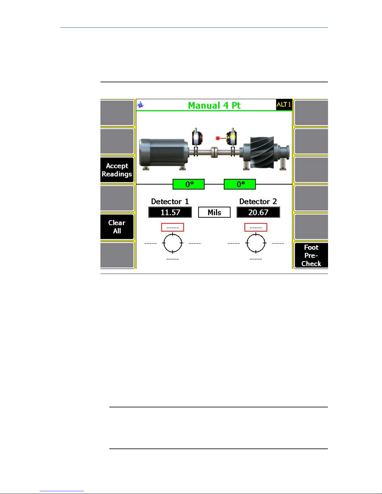
Manual 4 Point
Manual 4 PointFigure 4-3:
a. Position the laser and sensor at a starting angle (ideally at the first
cardinal position, 0°).
The laser and sensor angles should be within 2° of each other and
within 3° of the active cardinal position (0°, 90°, 180°, and 270°), if
possible. When this happens, the background of the box displayed
below the machine is green. If the laser and sensor angles are not
within 2° of each other and 3° of the active cardinal position, the box
background is white.
b.
Rotate the laser fixtures a full revolution stopping at each cardinal
position (0°, 90°, 180°, and 270°). Press F3 Accept Readings after
stopping at each point.
Note
While it is always desirable to measure at all four cardinal positions, it is
possible to estimate an alignment solution with only three
measurements.
Quick Start Guide December 2018
26 AMS 2140 Advanced Laser Alignment Application
Page 27

The status LED on the AMS 2140 flashes and an audible tone is
produced whenever a reading is taken. The audible tone is only
available when the Status Beeper is enabled (Home > ALT > F2 General
Setup > F3 Set Status Beeper).
c.
After taking readings for each of the cardinal position, press Enter.
4. If the Review Results option is enabled, review the results, view the
tolerance plots, or repeat the reading.
Refer to the Alignment chapter of the AMS 2140 Machinery Health
Analyzer User Guide for more information on reviewing alignment
measurement results.
5. After reviewing results, press Enter to advance to the next step (Move
Machine).
4.3 Align the machine
After you acquire alignment data, the Laser Align Application automatically
advances to the next step, which is to make adjustments on the machines to
align them (Move Machine), if necessary. After completing this step, the
Move Machine function on the Laser Align Application main menu is marked
with an X.
Procedure
1. After acquiring alignment data, press Enter.
2. Review the amount of required vertical and horizontal machine moves
and make the necessary adjustments to the machine.
December 2018 Quick Start Guide
Quick Start Guide 27
Page 28
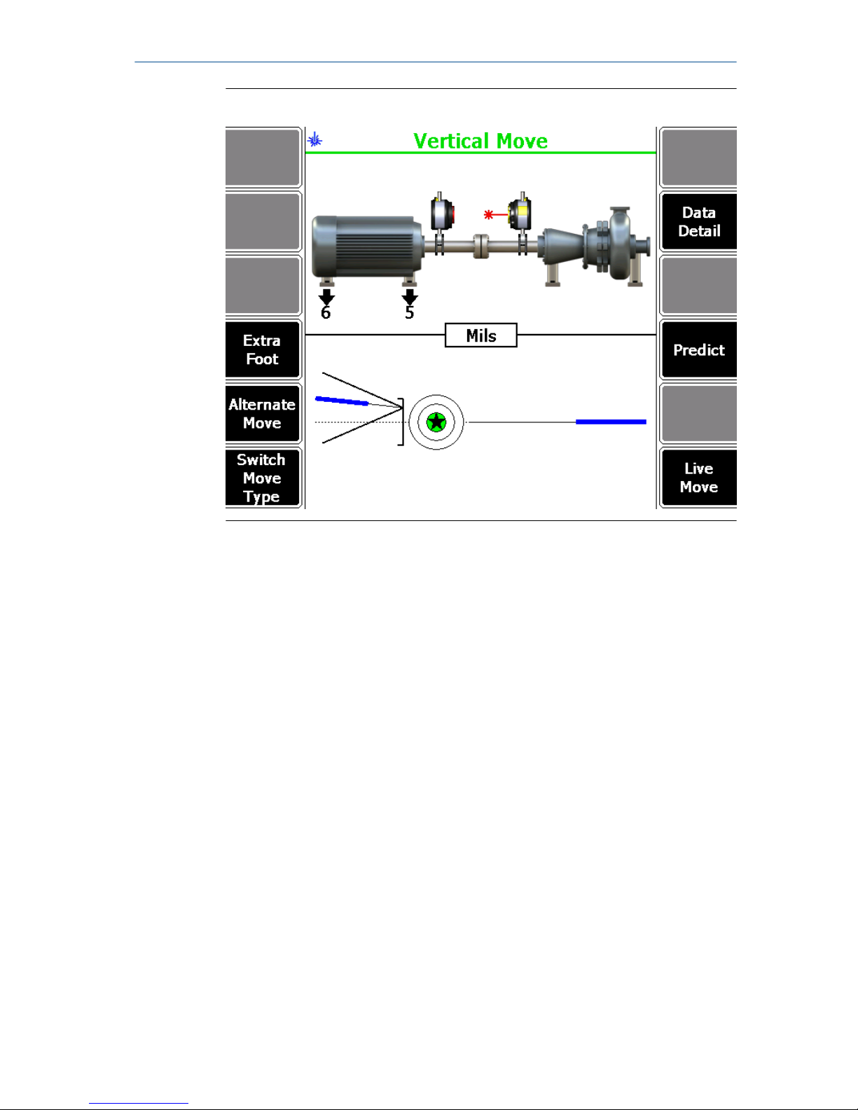
Vertical machine moveFigure 4-4:
For vertical machine moves, if the required movement is positive, the
amount of movement is shown above the machine at the appropriate
foot with an up arrow. If the required movement is negative, the amount
of movement is shown below the machine at the appropriate foot with a
down arrow.
Quick Start Guide December 2018
28 AMS 2140 Advanced Laser Alignment Application
Page 29
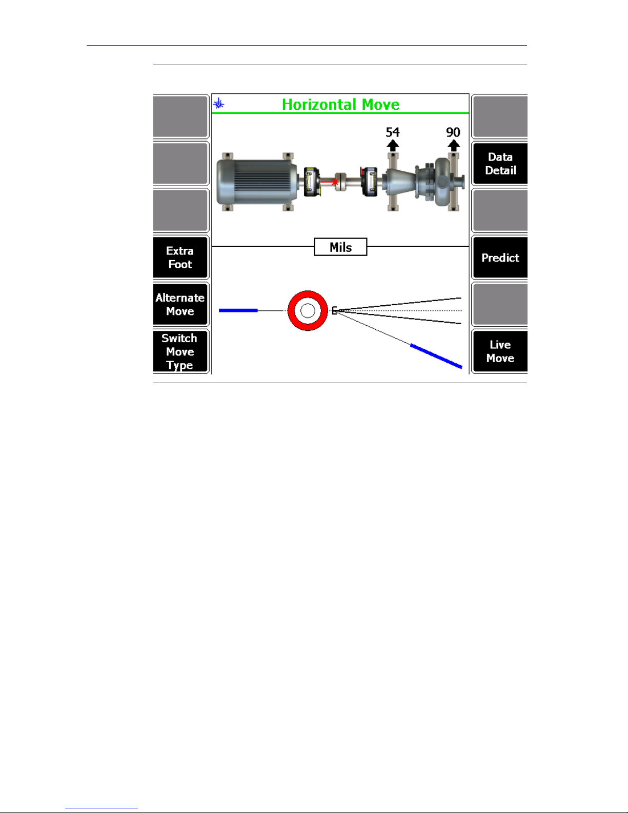
Horizontal machine moveFigure 4-5:
For horizontal machine moves, if the required movement is positive, the
amount of movement is shown below the machine at the appropriate
foot with a down arrow. If the required movement is negative, the
amount of movement is shown above the machine at the appropriate
foot with an up arrow.
The bottom half of the AMS 2140 screen shows a bull’s-eye target and a
shaft centerline plot representing the alignment condition of the
machine. The shaft centerline plot includes a “V” shape indicating the
acceptable angular tolerance on the machine as well as a bracket at the
base of the “V” showing the acceptable offset misalignment at the
coupling.
The bull’s-eye target compares the total misalignment to the target
tolerance. Each circle in the bull’s-eye target has a different meaning:
red—more than two times the tolerance, yellow—between one and two
times the tolerance, green—within acceptable tolerance, green with a
star—within excellent tolerance.
Optionally, you can do the following:
a.
Press F4 Extra Foot to calculate the vertical and horizontal machine
moves for up to four machine foot locations in addition to those
defined for the job.
December 2018 Quick Start Guide
Quick Start Guide 29
Page 30

Refer to the Alignment chapter of the AMS 2140 Machinery Health
Analyzer User Guide for more information on calculating extra
machine feet.
b.
Press F5 Alternate Move to switch between the alternate pairs of feet
where the machine moves can be made.
If all dimensions are entered, up to six alternate moves are available.
c. Press F6 Switch Move Type to select a move type. You can choose
vertical, horizontal, or vertical and horizontal.
d. Press F8 Data Detail to view the tolerance plots.
The tolerance plots are a graphical representation of the alignment
condition of the machine. Refer to the Alignment chapter of the AMS
2140 Machinery Health Analyzer User Guide for more information on
the tolerance plots.
e. Press F10 Predict to estimate the resulting alignment condition based
on a theoretical adjustment prior to actually moving the machine.
This is useful in determining whether appropriate shims are available
to correct the misalignment. Refer to the Alignment chapter of the
AMS 2140 Machinery Health Analyzer User Guide for more
information on the predict mode.
f. Press F12 Live Move to observe the machine movement in real time
from the AMS 2140 while making machine moves.
See Section 4.3.1 for more information on performing live move.
3. If necessary, acquire alignment data again. See Section 4.2.
4.3.1 Perform live move
The Live Move option lets you observe the machine movement from the AMS
2140 while you are moving the machine.
Only the horizontal live move is covered in this document.
Procedure
1. On the Machine Move screen, press F12 Live Move.
Note
This option is present on the Horizontal Move screen by default and is
also present depending on the live move orientation you have previously
chosen. See Section 3.3.8.
Quick Start Guide December 2018
30 AMS 2140 Advanced Laser Alignment Application
Page 31
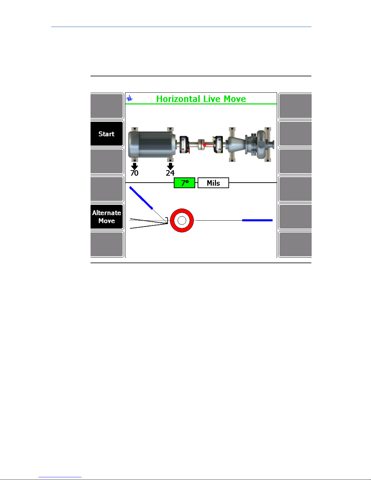
The screen then displays the movement required to align the machine
horizontally. The bull’s-eye target indicates how well the machine is
aligned with respect to tolerances.
Horizontal live moveFigure 4-6:
Perform the live move with the laser fixtures at any rotational position.
Before proceeding, make sure that the laser fixtures are located at a
position where they can remain stable throughout the alignment
process. The average laser and sensor angle position is displayed in the
middle of the screen. The background of the box is green when the laser
fixtures are within 2° of each other, and is white if the laser fixtures are not
within 2° of each other.
For horizontal machine moves, if the required movement is positive, the
amount of movement is shown below the machine at the appropriate
foot with a down arrow. If the required movement is negative, the
amount of movement is shown above the machine at the appropriate
foot with an up arrow.
The bottom half of the AMS 2140 screen shows a bull’s-eye target and a
shaft centerline plot representing the alignment condition of the
machine. The shaft centerline plot includes a “V” shape indicating the
acceptable angular tolerance on the machine as well as a bracket at the
base of the “V” showing the acceptable offset misalignment at the
coupling.
December 2018 Quick Start Guide
Quick Start Guide 31
Page 32

The bull’s-eye target compares the total misalignment to the target
tolerance. Each circle in the bull’s-eye target has a different meaning:
red—more than two times the tolerance, yellow—between one and two
times the tolerance, green—within acceptable tolerance, green with a
star—within excellent tolerance.
2.
Press F2 Start to start the live move.
a. Press F5 Alternate Move to select between the alternate pairs of feet.
3. Loosen the machine feet hold-down bolts, and then move the machine
until the target tolerance level is reached.
As the machine is moved, the bottom half of the AMS 2140 screen
provides a continuous update of the machine alignment condition.
When the live move alert is enabled, the status LED on the AMS 2140
flashes and an audible alert is heard (only when the Status Beeper is set to
on) when the target tolerance value is reached during a live move. See
Section 3.3.9 to enable live move alerts.
4. Tighten the machine hold-down bolts when you reach the target
alignment condition.
5. Press F2 Stop to stop the live move.
6. Acquire alignment data again to verify the machine alignment condition.
CAUTION!
A live machine move is not a reliable indicator of the final alignment
condition of a machine. There will be variability in the alignment data due
to shaft clearances, bearing faults, base deterioration, etc. Emerson
recommends acquiring a new set of alignment data after performing a
live move.
Quick Start Guide December 2018
32 AMS 2140 Advanced Laser Alignment Application
Page 33

5 Transfer alignment job data and tolerances
5.1 Transfer an alignment job to AMS Machinery Manager
Prerequisites
1.
Connect the AMS 2140 to a PC with AMS Machinery Manager installed
and running.
2. Set the connection type on the AMS 2140.
3. Enable the AMS 2140 in Data Transfer.
4. Set the connection type in Data Transfer. The connection type on the
AMS 2140 and on Data Transfer must match.
Refer to the AMS 2140 Machinery Health Analyzer User Guide for more
information on setting the connection type on the AMS 2140 and on AMS
Machinery Manager Data Transfer.
Procedure
1. From the Laser Align Application main menu, press ALT > F9 Job Manager >
F7 Connect for Transfer.
2. Optionally, press F1 Set Storage Location to select the internal memory or
an SD memory card.
This option is available only if a memory card is inserted into the AMS
2140.
3. Press F8 Dump Data.
4. Press F8 or F9 to select the job you want to transfer and press F1 Select.
5. Press F7 Begin Data Dump.
6. Press F8 or F9 to select a database.
7. Press F10 or F11 to select an area within the database and press F4 Select
Area.
8. Press F8 or F9 to select an equipment within the area and press F7 Select.
This transfers the alignment job to the selected equipment within the
database. The status of the data transfer is then displayed on the AMS
2140.
5.2 Load an alignment job from AMS Machinery Manager
Prerequisites
1. Connect the AMS 2140 to a PC with AMS Machinery Manager installed
and running.
December 2018 Quick Start Guide
Quick Start Guide 33
Page 34

2. Set the connection type on the AMS 2140.
3.
Enable the AMS 2140 in Data Transfer.
4. Set the connection type in Data Transfer. The connection type on the
AMS 2140 and on Data Transfer must match.
Refer to the AMS 2140 Machinery Health Analyzer User Guide for more
information on setting the connection type on the AMS 2140 and on AMS
Machinery Manager Data Transfer.
Procedure
1. From the Laser Align Application main menu, press ALT > F9 Job Manager >
F7 Connect for Transfer.
2. Optionally, press F1 Set Storage Location to select the internal memory or
an SD memory card.
This option is available only if a memory card is inserted into the AMS
2140.
3. Press F7 Load Jobs.
4. Press F8 or F9 to select a database.
5. Press F10 or F11 to select an area within the database and press F4 Select
Area.
6. Press F8 or F9 to select an equipment within the area and press F7 Select.
7. Press F8 or F9 to select a job and press F1 Select.
8. Press F7 Load Jobs.
5.3 Load tolerance table from AMS Machinery Manager
Alignment tolerance tables can only be transferred from the PC to the AMS
2140.
The alignment tolerance table contains the tolerance values for standard and
jackshaft tolerances as well as soft foot and frame distortion index (FDI)
tolerance values for horizontal alignment jobs.
Prerequisites
1. Connect the AMS 2140 to a PC with AMS Machinery Manager installed
and running.
2. Set the connection type on the AMS 2140.
3. Enable the AMS 2140 in Data Transfer.
4. Set the connection type in Data Transfer. The connection type on the
AMS 2140 and on Data Transfer must match.
Quick Start Guide December 2018
34 AMS 2140 Advanced Laser Alignment Application
Page 35

Refer to the AMS 2140 Machinery Health Analyzer User Guide for more
information on setting the connection type on the AMS 2140 and on AMS
Machinery Manager Data Transfer.
Procedure
1.
From the Laser Align Application main menu, press ALT > F9 Job Manager >
F7 Connect for Transfer.
2. Optionally, press F1 Set Storage Location to select the internal memory or
an SD memory card.
This option is available only if a memory card is inserted into the AMS
2140.
3. Press F9 Load Tolerance Table.
4. Press F8 or F9 to select a database containing the tolerance table.
5. Press F7 Load Tolerance Table.
6. Select YES to load the tolerance table and overwrite the existing
tolerance table in the AMS 2140.
December 2018 Quick Start Guide
Quick Start Guide 35
Page 36

6 Print alignment summary reports
6.1 Print an alignment summary report to AMS Machinery
Manager
Prerequisites
• On the AMS 2140, press Home > ALT > F2 General Setup > F6 Set Print Mode
and ensure the default print mode is set to Send to PC.
• Ensure the same connection type is set on the AMS 2140 and in Data
Transfer. The Ethernet and Wireless options may require additional setup
to connect to the desired computer. Refer to the AMS 2140 Machinery
Health Analyzer User Guide for more information.
Procedure
1.
Activate an alignment job.
2. Use the appropriate cable to connect your AMS 2140 to a computer
where AMS Machinery Manager is installed, if you are using a wired
connection.
3. On the computer, open Data Transfer.
4. From the Laser Align Application main menu, press ALT > F11 Print Job.
The AMS 2140 connects to Data Transfer and displays the summary
report. From the navigation bar in Data Transfer, you can preview the job,
save it as an image file, or add a cover sheet. See the AMS Machinery
Manager Help for more information.
5. From AMS Machinery Manager, click the print icon to send the report to a
printer.
6. To disconnect, click Disconnect on the Data Transfer tab.
6.2 Print an alignment summary report to a memory card
You can save a report to a memory card if you inserted a card into the AMS
2140.
Prerequisites
On the AMS 2140, press Home > ALT > F2 General Setup > F6 Set Print Mode and
ensure the default print mode is set to Store as BMP on CARD or Store as JPG on
CARD.
Procedure
1. From the Laser Align Application main menu, press ALT > F11 Print Job.
Quick Start Guide December 2018
36 AMS 2140 Advanced Laser Alignment Application
Page 37

2. Enter up to 8 characters for a file name and press Enter.
The AMS 2140 creates and saves the file to the memory card. The
progress is displayed on the screen.
December 2018 Quick Start Guide
Quick Start Guide 37
Page 38
7 Verify the AMS Machinery Manager version
The AMS 2140 Laser Align Application is compatible with AMS Machinery
Manager v5.61 or later.
AMS Machinery Manager 5.61 may require a patch to enable full
functionality. If you are using AMS Machinery Manager v5.61, perform the
following steps to verify that the patch is installed on your PC.
Procedure
1.
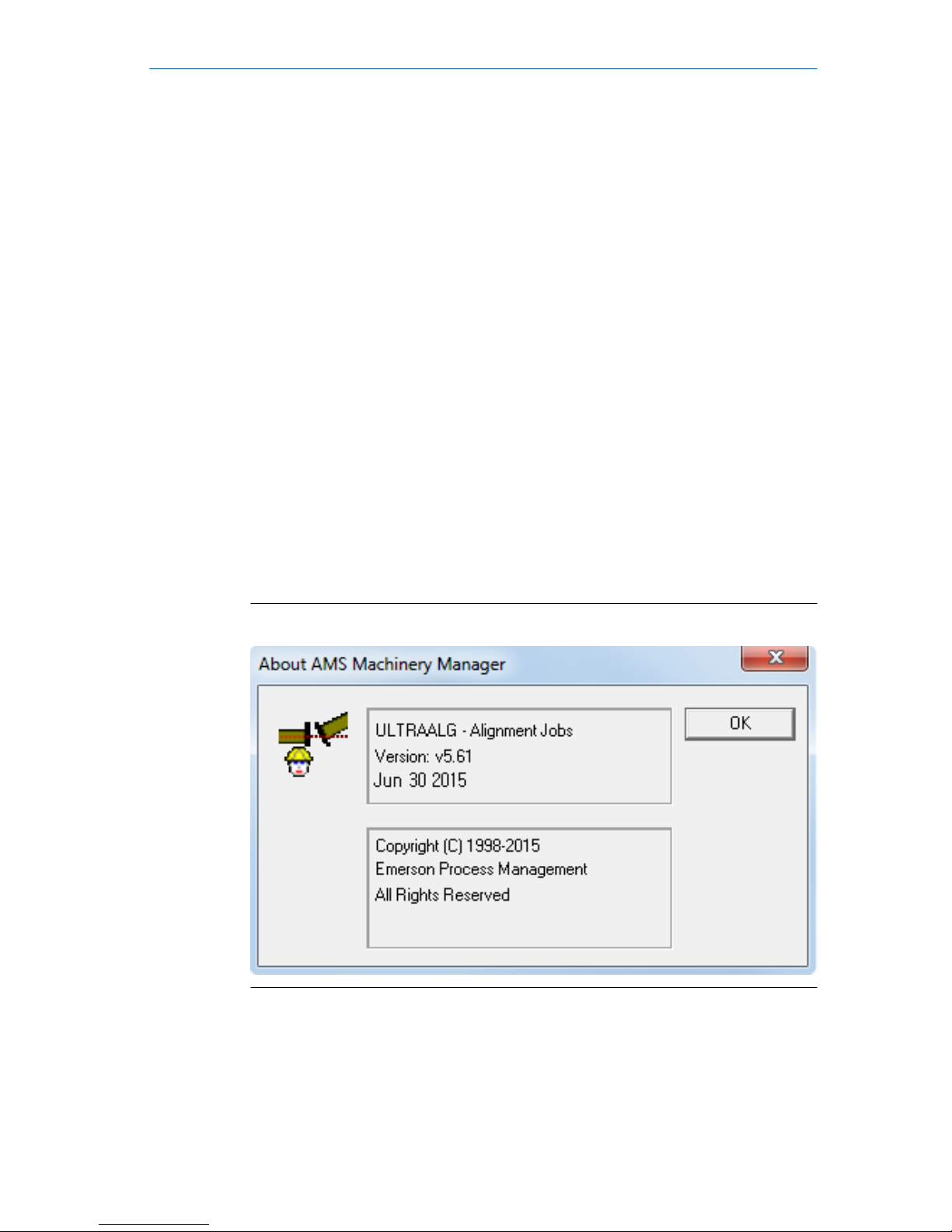
From AMS Machinery Manager, click Help > About AMS Suite: Machinery Health
Manager and verify the version you are using is v5.61.
2. Select the Tools tab.
3. From the Filters pane, select Document/Reporting.
4. Double-click Alignment Jobs to launch the UltraAlg application.
5. From the UltraAlg application, click Help > About.
Verify the release date of the UltraAlg application. It should be June 30,
2015 or later.
About AMS Machinery ManagerFigure 7-1:
Quick Start Guide December 2018
38 AMS 2140 Advanced Laser Alignment Application
Page 39
Appendix A
sensALIGN approvals
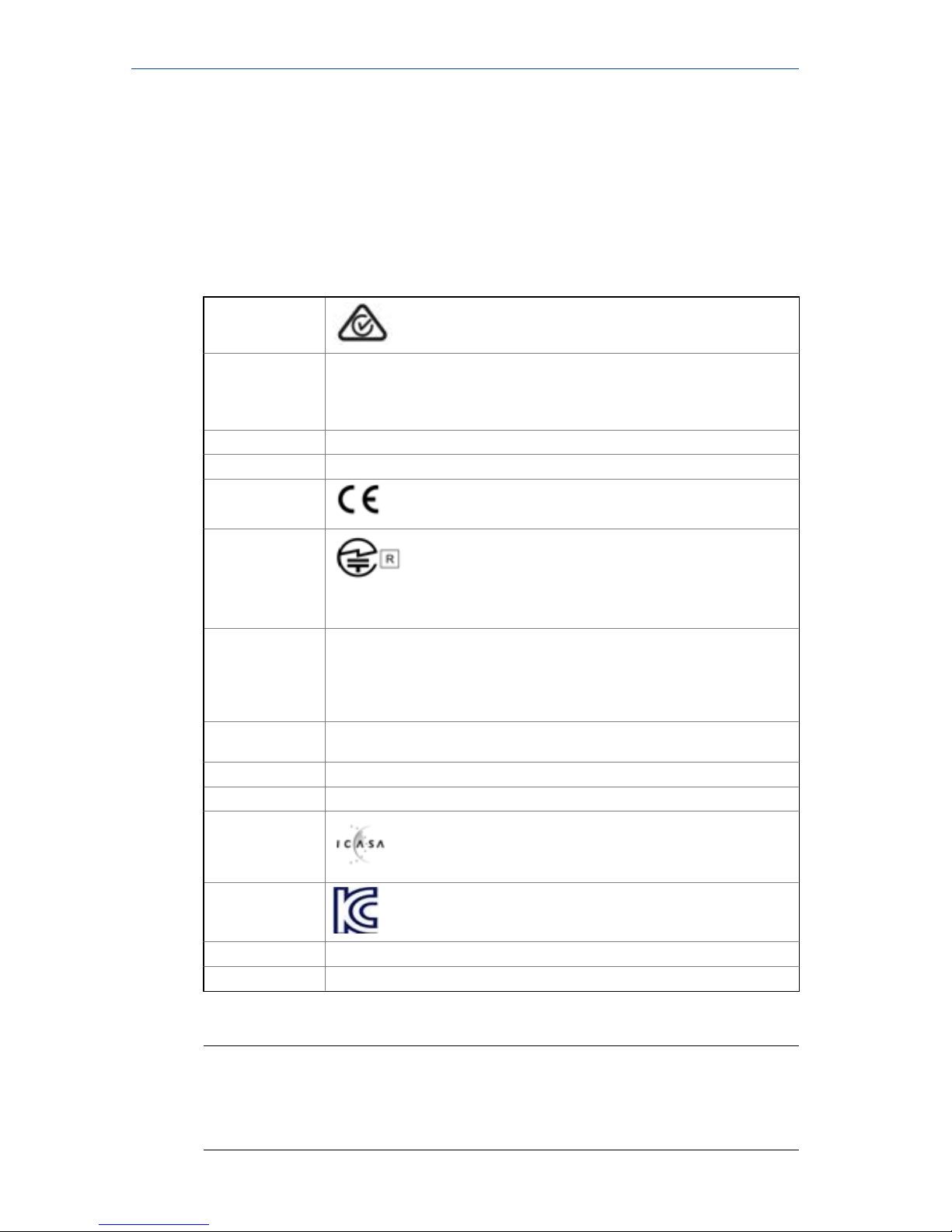
The sensALIGN sensor complies with the following approvals:
Australia
Brazil ANATEL: 1812-15-4219
Este equipamento opera em caráter secundário, isto é, não tem direito a
proteção contra interferência prejudicial, mesmo de estações do mesmo
tipo, e não causar interferência a sistema operando em caráter primário.
Canada IC: 5123A-BGTWT41
China CMIIT ID: 2015DJ1567
Europe
Japan
209-J00047
当該機器には電波法に基づく、
技術基準適合証明等を受けた特定無線設備
を装着している
Mexico IFETEL: RCPPRAL15-0647
La operación de este equipo está sujeta a las siguientes dos condiciones: (1)
es posible que este equipo o dispositivo no cause interferencia perjudicial y
(2) este equipo o dispositivo debe aceptar cualquier interferencia,
incluyendo la que pueda causar su operación no deseada.
Nigeria Connection and use of this communications equipment is permitted by the
Nigerian Communications Commission
Pakistan Approved by PTA, 2015
Singapore Complies with IDA Standards N0817-15
South Africa
TA 2015-559 APPROVED
South Korea
MSIP-CRM-PRc-sensALIGNsens
UAE TRA REGISTERED No: ER39483/15, DEALER No: DA43636/15
USA FCC: QOQWT41
Note
The table above does not include all countries for which certificates have
been issued. For a complete list, please contact your local Emerson Sales
Representative.
December 2018 Quick Start Guide
Quick Start Guide 39
Page 40

Quick Start Guide
MHM-97390, rev. 1
December 2018
Emerson
835 Innovation Drive
Knoxville, TN 37932 USA
T +1 865-675-2400
F +1 865-218-1401
www.Emerson.com
©
2018, Emerson.
The contents of this publication are presented for
informational purposes only, and while every effort
has been made to ensure their accuracy, they are
not to be construed as warranties or guarantees,
express or implied, regarding the products or
services described herein or their use or
applicability. All sales are governed by our terms
and conditions, which are available on request. We
reserve the right to modify or improve the designs
or specifications of our products at any time
without notice.
All rights reserved. The Emerson logo is a
trademark and service mark of Emerson Electric Co.
All other marks are property of their respective
owners.
 Loading...