

Page 1
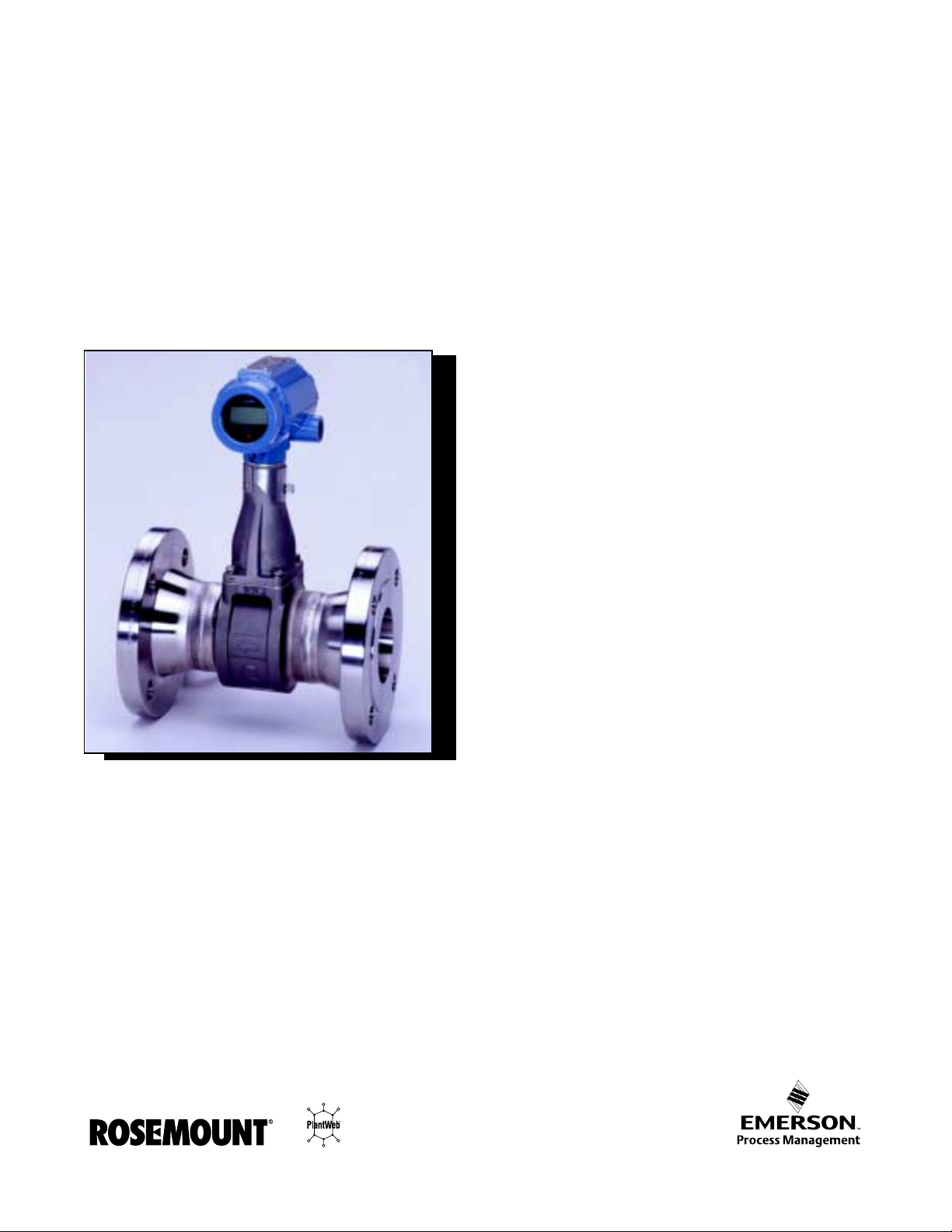
Model 8800C and Model 8800A Smart Vortex Flowmeter
00809-0100-4003
English
Rev. JA
Page 2

Page 3
Product
Manual
Model 8800C and Model 8800A
Smart Vortex Flowmeter
NOTICE
Read this manual before working with the product. For personal and system safety, and
for optim um product performance, make sure you thoroughly understand the contents
before installing, using, or maintaining this product.
Within the United States, Rosemount Inc. has two toll - free assistance numbers:
Customer Central
Technic al support, quoting, and order-related questions.
1-800-999-9307 (7:00 am to 7:00 pm CST)
North American Response Center
Equipment service needs.
1-800-654-7768 (24 hours—includes Canada)
Outside of the Unit ed States, contact your local Ros emount represent ative.
Rosemount Inc.
8200 Market Boulevard
Chanhassen, MN 55317
USA
Tel 1-800-999-9307
Fax (952) 949-7001
© 2000 Rosemount, Inc.
Fisher-Rosemount Flow
Groene veldselaan 6-8
3903 AZ Veenendaal
The Netherlands
Tel 31 (0) 318 549 549
Fax 31 (0) 318 549 559
Tel 0800-966-180 (U .K. only)
Fax 0800-966-181 (U.K. only)
¢00809-0100-4003s¤
00809-0100-4003, Rev. JA, 4/01
The products described in this document are NOT designed for nuclear-qualified
applications. Using non-nuclear qualified products in applications that require nuclearqualified hardware or products may cause inaccurate readings.
For inf o rmation on Rosemou nt n uclea r-qu alif ied pr oduct s, con tact y ou r l ocal R ose moun t
Sales Representative.
.
Rosemoun t , the Rosemo un t l ogotype , Fisher-Ros em ount, Mana ging the Pr ocess Better, an d P lantWe b are
marks of one of the Fisher-Rosemount group of companies.
HART is a registered trademark of the HART Communication Foundation.
Hastelloy C is a r egistered trademark o f H aynes International Inc.
Inconel is a registered trademark of International Nickel Co.
Cover photo: 8800- 8800C918
Fisher-Rosemount
Singaport Pte Ltd.
1 Pandan Crescent
Singapore 128461
Tel (65) 777-8211
Fax (65) 777-0947
[email protected]
Product documentation available at...
www.rosemount.com
Fisher-Rosemount
satisfies all obligations
coming from le gislatio n
to harmonise product
requirements in the
European Union .
Page 4

Rosemount Model 8800C Vortex Flowmeter
Page 5

Table of Contents
SECTION 1 Introduction
SECTION 2 Installation
How to Use this Manual . . . . . . . . . . . . . . . . . . . . . . . . . . . . . . . . . . 1-1
Safety Messages. . . . . . . . . . . . . . . . . . . . . . . . . . . . . . . . . . . . . . . . . 1-1
Safety Messages. . . . . . . . . . . . . . . . . . . . . . . . . . . . . . . . . . . . . . . . . 2-1
Commissioning. . . . . . . . . . . . . . . . . . . . . . . . . . . . . . . . . . . . . . . . . . 2-3
General C o ns i d erations . . . . . . . . . . . . . . . . . . . . . . . . . . . . . . . . . . . 2-3
Flowmeter Sizing . . . . . . . . . . . . . . . . . . . . . . . . . . . . . . . . . . . . . 2-3
Flowmeter Orientation. . . . . . . . . . . . . . . . . . . . . . . . . . . . . . . . . 2-3
Wetted Mater ia l Selection . . . . . . . . . . . . . . . . . . . . . . . . . . . . . . 2-5
Environmental Considerations . . . . . . . . . . . . . . . . . . . . . . . . . . 2-5
Hazardous Locations . . . . . . . . . . . . . . . . . . . . . . . . . . . . . . . . . . . . . 2-6
Hardware Con figuration. . . . . . . . . . . . . . . . . . . . . . . . . . . . . . . . . . 2-6
Failure Mode vs. Saturation Output Values. . . . . . . . . . . . . . . . 2-7
LCD Indicator Option. . . . . . . . . . . . . . . . . . . . . . . . . . . . . . . . . . 2-8
Installation Tasks . . . . . . . . . . . . . . . . . . . . . . . . . . . . . . . . . . . . . . . 2-8
Handling . . . . . . . . . . . . . . . . . . . . . . . . . . . . . . . . . . . . . . . . . . . . 2-8
Flow Direction. . . . . . . . . . . . . . . . . . . . . . . . . . . . . . . . . . . . . . . . 2-8
Gaskets . . . . . . . . . . . . . . . . . . . . . . . . . . . . . . . . . . . . . . . . . . . . . 2-8
Flange Bolts . . . . . . . . . . . . . . . . . . . . . . . . . . . . . . . . . . . . . . . . . 2-9
Wafer-Style Flowmeter Alignment and Mounting . . . . . . . . . . 2-10
Flanged-Style Flowmeter Mo u n ting . . . . . . . . . . . . . . . . . . . . . 2-12
Flowmeter Grounding . . . . . . . . . . . . . . . . . . . . . . . . . . . . . . . . 2-13
Electroni cs Considerations. . . . . . . . . . . . . . . . . . . . . . . . . . . . . 2-13
Conduit Connections . . . . . . . . . . . . . . . . . . . . . . . . . . . . . . . . . 2-13
High-Point Installation . . . . . . . . . . . . . . . . . . . . . . . . . . . . . . . 2-13
Cable Gland. . . . . . . . . . . . . . . . . . . . . . . . . . . . . . . . . . . . . . . . . 2-14
Grounding th e T ra n smitter Case . . . . . . . . . . . . . . . . . . . . . . . 2-14
Wiring Procedure . . . . . . . . . . . . . . . . . . . . . . . . . . . . . . . . . . . . 2-27
Remote Electronics. . . . . . . . . . . . . . . . . . . . . . . . . . . . . . . . . . . 2-31
Calibration . . . . . . . . . . . . . . . . . . . . . . . . . . . . . . . . . . . . . . . . . 2-32
Software C o n figurati o n. . . . . . . . . . . . . . . . . . . . . . . . . . . . . . . . . . 2-32
Options . . . . . . . . . . . . . . . . . . . . . . . . . . . . . . . . . . . . . . . . . . . . . . . 2-33
LCD Indicat o r . . . . . . . . . . . . . . . . . . . . . . . . . . . . . . . . . . . . . . . . . 2-33
Installin g the Indicato r . . . . . . . . . . . . . . . . . . . . . . . . . . . . . . . 2-34
Diagnostic Messages. . . . . . . . . . . . . . . . . . . . . . . . . . . . . . . . . . 2-35
Transient Pr otection . . . . . . . . . . . . . . . . . . . . . . . . . . . . . . . . . . . . 2-36
Installing the Transient Protector. . . . . . . . . . . . . . . . . . . . . . . 2-36
1
Page 6

Rosemount Model 8800C Smart Vortex Flowmeter
SECTION 3 Operation
Review . . . . . . . . . . . . . . . . . . . . . . . . . . . . . . . . . . . . . . . . . . . . . . . . 3-1
Process Variables. . . . . . . . . . . . . . . . . . . . . . . . . . . . . . . . . . . . . . . . 3-1
Totalizer . . . . . . . . . . . . . . . . . . . . . . . . . . . . . . . . . . . . . . . . . . . . 3-2
Diagnost ics/Service . . . . . . . . . . . . . . . . . . . . . . . . . . . . . . . . . . . . . . 3-3
Test/Status . . . . . . . . . . . . . . . . . . . . . . . . . . . . . . . . . . . . . . . . . . 3-3
Loop Test. . . . . . . . . . . . . . . . . . . . . . . . . . . . . . . . . . . . . . . . . . . . 3-3
Pulse Outpu t Test. . . . . . . . . . . . . . . . . . . . . . . . . . . . . . . . . . . . . 3-3
Flow Simulation . . . . . . . . . . . . . . . . . . . . . . . . . . . . . . . . . . . . . . 3-3
D/A Trim . . . . . . . . . . . . . . . . . . . . . . . . . . . . . . . . . . . . . . . . . . . . 3-5
Scaled D/ A Trim . . . . . . . . . . . . . . . . . . . . . . . . . . . . . . . . . . . . . . 3-5
Shed Freq at URV. . . . . . . . . . . . . . . . . . . . . . . . . . . . . . . . . . . . . 3-5
Basic Setup. . . . . . . . . . . . . . . . . . . . . . . . . . . . . . . . . . . . . . . . . . . . . 3-5
Tag. . . . . . . . . . . . . . . . . . . . . . . . . . . . . . . . . . . . . . . . . . . . . . . . . 3-5
Service Type . . . . . . . . . . . . . . . . . . . . . . . . . . . . . . . . . . . . . . . . . 3-5
PV Units . . . . . . . . . . . . . . . . . . . . . . . . . . . . . . . . . . . . . . . . . . . . 3-6
Range Values . . . . . . . . . . . . . . . . . . . . . . . . . . . . . . . . . . . . . . . 3-10
Process Tem pera ture . . . . . . . . . . . . . . . . . . . . . . . . . . . . . . . . . 3-10
Mating Pipe I D ( In s ide Diameter). . . . . . . . . . . . . . . . . . . . . . . 3-11
Damping . . . . . . . . . . . . . . . . . . . . . . . . . . . . . . . . . . . . . . . . . . . 3-11
Advanced Functionality. . . . . . . . . . . . . . . . . . . . . . . . . . . . . . . . . . 3-12
Detailed Set-Up . . . . . . . . . . . . . . . . . . . . . . . . . . . . . . . . . . . . . . . . 3-12
Characterize Meter. . . . . . . . . . . . . . . . . . . . . . . . . . . . . . . . . . . 3-12
PV Units . . . . . . . . . . . . . . . . . . . . . . . . . . . . . . . . . . . . . . . . . . . 3-14
Configure O p tions. . . . . . . . . . . . . . . . . . . . . . . . . . . . . . . . . . . . 3-14
HART Output . . . . . . . . . . . . . . . . . . . . . . . . . . . . . . . . . . . . . . . 3-17
Signal Processing . . . . . . . . . . . . . . . . . . . . . . . . . . . . . . . . . . . . 3-20
Device Information . . . . . . . . . . . . . . . . . . . . . . . . . . . . . . . . . . . 3-23
SECTION 4 Hardware and Software Maintenance and Troubleshooting
Safety Messages. . . . . . . . . . . . . . . . . . . . . . . . . . . . . . . . . . . . . . . . . 4-1
Troubles h ooting Tables . . . . . . . . . . . . . . . . . . . . . . . . . . . . . . . . . . . 4- 3
Advanced Troubleshootin g . . . . . . . . . . . . . . . . . . . . . . . . . . . . . . . . 4-6
TP1 . . . . . . . . . . . . . . . . . . . . . . . . . . . . . . . . . . . . . . . . . . . . . . . . 4-7
Shedding Freq u e n cy Out . . . . . . . . . . . . . . . . . . . . . . . . . . . . . . . 4-9
Testing proc edu res. . . . . . . . . . . . . . . . . . . . . . . . . . . . . . . . . . . . . . . 4-9
Hardware Replacement. . . . . . . . . . . . . . . . . . . . . . . . . . . . . . . . . . 4-10
Replacing the Terminal Block in th e Housing . . . . . . . . . . . . . 4-11
Replacing the Electronics Bo ards . . . . . . . . . . . . . . . . . . . . . . . 4-12
Replacing the Electronics H o us ing . . . . . . . . . . . . . . . . . . . . . . 4-13
Replacing the Sensor . . . . . . . . . . . . . . . . . . . . . . . . . . . . . . . . . 4-15
Replacing the Sensor: Remo vable and
Integral Support Tubes . . . . . . . . . . . . . . . . . . . . . . . . . . . . . . . 4-17
Remote Elec tronics Proce d u r e. . . . . . . . . . . . . . . . . . . . . . . . . . 4-22
Coaxial Ca ble a t the Electroni cs Housing. . . . . . . . . . . . . . . . . 4-25
Changing th e Housing Orientation. . . . . . . . . . . . . . . . . . . . . . 4-26
Return of Material. . . . . . . . . . . . . . . . . . . . . . . . . . . . . . . . . . . . . . 4-27
2
Page 7

Table of Contents
APPENDIX A Reference Data
APPENDIX B Approvals
APPENDIX C HART Communicator
APPENDIX D Model 268 Communicator
APPENDIX E Electronics Verification
Functional Specifications . . . . . . . . . . . . . . . . . . . . . . . . . . . . . . . . .A-1
Performan c e S p ecifications. . . . . . . . . . . . . . . . . . . . . . . . . . . . . . . .A-6
Physical Specifications . . . . . . . . . . . . . . . . . . . . . . . . . . . . . . . . . . A-11
Hazardous Locations Certifications . . . . . . . . . . . . . . . . . . . . . . . .A-13
European Atex Directive Information . . . . . . . . . . . . . . . . . . . . . .A-1 6
Ordering Information . . . . . . . . . . . . . . . . . . . . . . . . . . . . . . . . . . .A-17
Connection s and Hardware. . . . . . . . . . . . . . . . . . . . . . . . . . . . . . . .C-6
Diagnostic Messa g e s. . . . . . . . . . . . . . . . . . . . . . . . . . . . . . . . . . .C-7
Diagnostics Messages. . . . . . . . . . . . . . . . . . . . . . . . . . . . . . . . . .D-4
Safety Messages. . . . . . . . . . . . . . . . . . . . . . . . . . . . . . . . . . . . . . . . .E-1
Electro n ic s V e rificatio n . . . . . . . . . . . . . . . . . . . . . . . . . . . . . . . . . . .E-2
Electronics Verificati on Using Flow Simulati onMode. . . . . . . .E-2
Fixed Flow Rate Simulation. . . . . . . . . . . . . . . . . . . . . . . . . . . . .E-2
Varying Flow Rate Simulation . . . . . . . . . . . . . . . . . . . . . . . . . .E-2
Electronics Verification Using an
External Fr equ ency Generator . . . . . . . . . . . . . . . . . . . . . . . . . .E-3
Calculating Output Variables with Known Input Frequency . .E-4
Examples . . . . . . . . . . . . . . . . . . . . . . . . . . . . . . . . . . . . . . . . . . . . . . E-6
English Units . . . . . . . . . . . . . . . . . . . . . . . . . . . . . . . . . . . . . . . .E-6
SI Units . . . . . . . . . . . . . . . . . . . . . . . . . . . . . . . . . . . . . . . . . . . . . E-9
3
Page 8

Rosemount Model 8800C Smart Vortex Flowmeter
4
Page 9

Section
1 Introduction
How to Use this Manual . . . . . . . . . . . . . . . . . . . . . . . . . . . page 1-1
Safety Messages . . . . . . . . . . . . . . . . . . . . . . . . . . . . . . . . page 1-1
HOW TO USE
THIS MANUAL
This manual provides installation, configuration, troubleshooting, and
other procedures for the use of the Rosemount Model 8800C Smart
Vortex Flowmet e r. Specifications and other imp or tant information ar e
also inc lu d ed.
Section 2: Installation
provides assistance in hardware configuration and lists the options
available to customers for the Model 8800C.
Section 3: Op eratio n
describes the Model 8800C software functions, configuration
parameters, and other online variables. The descriptions are provided
according to the function you want to perform.
Section 4: Hardware and Software Maintenance and Troubleshooting
supplies troubleshooting tables to lead you through any problems that
may arise in the use of the Model 8800C. There are also inst ruc tio ns on
basic maintenance of your Model 8800C.
Appendix A: Reference Data
gives reference and specification data for the Model 8800C and its
applications.
Appendix B: Approvals
shows accompanying drawings for the Model 8800C FM and CSA
approvals and certi fications.
Appendix C: HART Communicator
provides command tree, and Fast Key Sequence tables for the HART
Communicator when used in conjunction with the Model 8800C.
Appendix D: Model 268 Communicator
supplies command tree, and Fast Key Sequence tables for the Model
268, when used in conjunction with the Model 8800C.
Appendix E: Electroni cs Verification
provides a short proc edure for verificati on of electronic output to
assist in meeting the quality standards for ISO 9000 cer tified
manufacturing processes.
SAFETY MESSAGES Procedu r es and inst ru ctions in th is manua l may re quire special
precautions to ensure the safety of the personne l performing the
operations. Refer to the safety messages, listed at the beginning
of each section , before performing any operati ons.
1-1
Page 10

Rosemount Model 8800C Vortex Flowmeter
1-2
Page 11
Section
2 Installation
Safety Messages . . . . . . . . . . . . . . . . . . . . . . . . . . . . . . . . page 2-1
Commis s io n in g . . . . . . . . . . . . . . . . . . . . . . . . . . . . . . . . . page 2-3
General C o n s id e rations . . . . . . . . . . . . . . . . . . . . . . . . . . . p ag e 2 -3
Hazardous L o c at io n s . . . . . . . . . . . . . . . . . . . . . . . . . . . . . page 2-6
Hardware Configuratio n . . . . . . . . . . . . . . . . . . . . . . . . . . . page 2-6
Installa ti o n Tasks . . . . . . . . . . . . . . . . . . . . . . . . . . . . . . . . page 2-8
Software C o nf ig u r a tion . . . . . . . . . . . . . . . . . . . . . . . . . . . page 2 -3 2
Options . . . . . . . . . . . . . . . . . . . . . . . . . . . . . . . . . . . . . . . . page 2 -3 3
LCD Indic a to r . . . . . . . . . . . . . . . . . . . . . . . . . . . . . . . . . . .page 2-33
Transien t P rotec tion . . . . . . . . . . . . . . . . . . . . . . . . . . . . . . page 2 -3 6
This section provides installation instructions for the Model 8800C
Vortex Flowmeter. Dimensional drawings for each Model 8800C
variation and mounting configuration are included in this section.
The options available for the Mo del 8800C flowmeter are also descri bed
in this section. The numbers in parentheses refer to the codes used to
order each option.
SAFETY MESSAGES Instructions and procedures in this section may require special
precautions to ensure the safety of the personne l performing the
operations. Please refer to the following safety messages before
performing any operation in this section.
Explosions could result in death or serious injury:
• Do not remove the tr ansmi tte r cov e r in e xpl os iv e atmo spher es wh en the c ircuit
is alive.
• Before connecting a HART-based communicator in an explosive atmosphere,
make sure the instruments in the loop are installed in accordance with
intrinsically safe or non-i ncendive field wiring pr actices.
• V eri fy that the operat i ng atmosphere of the transmitter i s consistent with the
appropriate hazardous locations certifi cations.
• Both transmitter covers must be fully engaged to meet explosion-proof
requirements.
Failure to follow these install ation guidelines could result in death or serious injury:
• Make sure only qualified personnel perform the instal lation.
2-1
Page 12
Rosemount Model 8800C Vortex Flowmeter
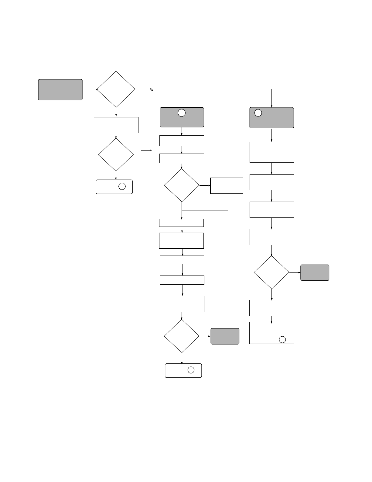
Figure 2-1. Installation Flowchart
START HERE
Bench
Commissioning?
Yes
Review
Configuration
Is
Configuration
OK?
No
Go to
A
Yes
No
A
CONFIGURE
Service Type
Set Units
Are you
using mass
units?
No
Set Range Values
Set Process
Temperature
Set Pipe ID
Verify K-Factor
Yes
Set Proces s
Density
B
FIELD
INSTALL
Mount
Flowmeter
Mount
Conduit
Wire
Flowmeter
Power
Flowmeter
Did you
Configure on
Bench?
Yes
DONE
2-2
Transfer Data to
Flowmeter
Is meter
installed?
No
Go to
B
Yes
DONE
No
Review
Configuration
Configure if
Necessary
Go to
A
Page 13

Installation
COMMISSIONING Commission the Model 8800C bef ore putting it into operation. This
ensures proper configur ation and opera tion of the meter. It also enables
you to check hardware settings, test the flowmeter electronics, verify
flowmeter configuration data, and check output variables. Any
problems can be correct ed – or configuration setti ngs changed – before
going out into the installation environment. To commission on the
bench, connect the HART
Solutions
signal loop in accor dance with the spec ificatio ns for y our com municator.
See Appendices C, D, and E for additional info rm ation.
™
(AMS) software (or other communications device) to the
®
Communicator or Asset Management
GENERAL CONSIDERATIONS
Before you install a flowmete r in any application, you must consider
flowmeter sizing (the line size) and location. Choose the correct
flowmeter size for a n appli cation to in crea se ran geabi lity and minim ize
pressure drop and cavitation. Proper location of the flowmeter can
ensure a clean and accurate signal. Follow the installation instructions
carefully to reduce start-up delays, ease maintenance, and ensure
optimum performance.
Flowmete r Sizing Correct meter sizing is important for flowm eter performance . The
Model 8800C is capable of processing signals from flow applications
within th e limitations described in Ap pe ndix A: Re fe rence Dat a. Full
scale is continuously adjustable within these ranges.
To determine the correct flowmeter size for an application, process
conditions must be withi n the stated requirements for Reynolds
number and velocit y. See Appendix A: Reference Data for sizing data .
Contact your local Rosemount Inc. sales represen tati ve t o obtai n a cop y
of the Model 8800C Vortex Flowmeter Sizing Program which calculates
flowmeter sizes bas ed on user-suppli ed input.
Flowmete r Or ientati on Design process pipi ng so the meter body will remain fu ll, with no
entrapped air. Allow enough straight pipe both upstream and
downstream of the meter body to ensure a nonskewed, symmetrical
profile . Install valves downstream of the meter when possible.
Vertical Installation
Vertical installation allows upward process liquid flow and is generally
preferred. Upward flow ensures that the meter body always remains
full and that any solids in the fluid are evenly distributed.
The vortex meter can be mounted in the vertical down position when
measuring gas or steam f lows. This type of applic ation should be
strongly discouraged for liquid flows, although it can be done with
prope r pi ping design.
NOTE
To ensure that the meter body remains full, avoi d down w a rd vertical
liquid flows where back pressure is inadequate.
2-3
Page 14
Rosemount Model 8800C Vortex Flowmeter
High-Temperature Installations
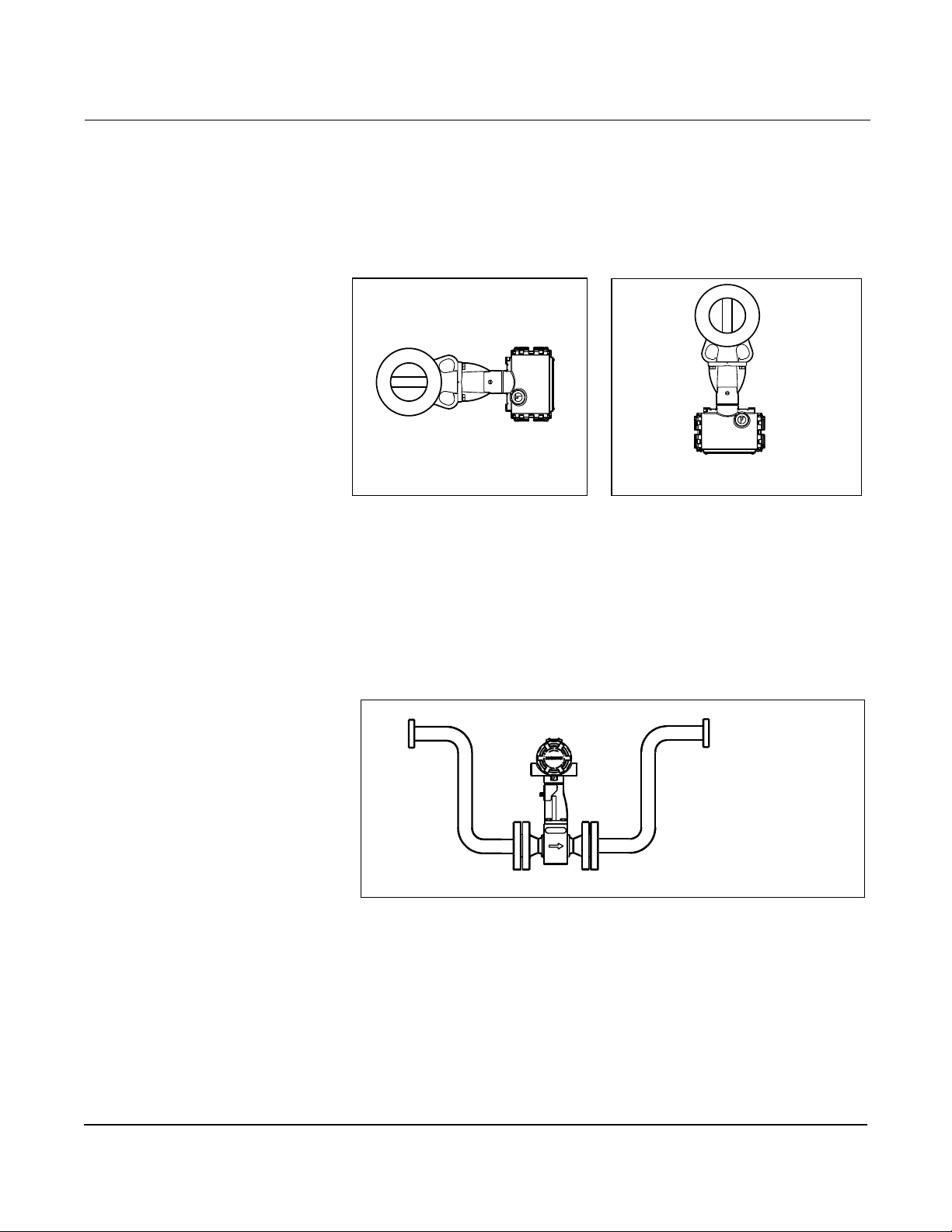
Install the mete r body so the electronic s are posi tioned to the side of t he
pipe or below the pipe as shown in Figure 2-2. Insulation may be
required around the pipe to maintain a temperature below 185 °F
(85 °C).
Figur e 2-2. Examples of Hig h-Temperature Installat ions
The meter body installed with the
electronics to the side of the pipe.
Steam Installations
The meter body installed with the
electronics below the pipe.
8800-0002A01C
For steam applications, avoid installations , such as the one shown in
Figure 2-3. Such installations may cause a water-hammer condition at
start-up due to trapped condensate. The high force from the water
hammer can over stress the sensing mechanism and cause permanent
damage to the sensor.
Figure 2-3. Avoid This Type of Installation for Steam Applications
8800-8800G15B
2-4
Page 15
Upstream/Downstream Piping
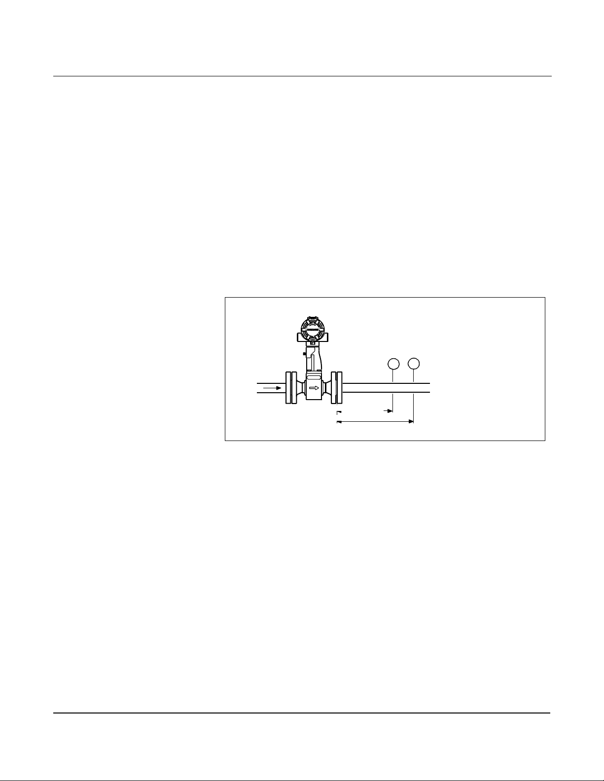
The vortex meter may be installed with a minimum of ten straight pipe
diameters (D) upstream and five straight p i p e di ameters (D )
downstream.
Rated accuracy is based on the number of pipe diameters from an
upstream disturbance. An additional 0.5% shift in K-factor may be
introduced between 10 D and 35 D , depending on disturbance . F or mor e
informa t io n on instal lation eff e ct s, see Technical Data S h eet
00816-0100-3250. This effect can also be corrected in the electronics.
See Installation Effect on page 3-13.
Pressure and Temperature Transmitter Location
When using pressure and temperature transmitt ers in conjunction
with the Model 8800C for compensated mass flows, install the
transmitter downstream of the Vortex Flowmeter. See Figure 2-4.
Figure 2-4. Pressure and Temperature Transmitter Location
Installation
P T
4 Downstream
6 Downstream
8800-8800G15A
Wetted Material Selection Ensure that the process fluid is compatible with the meter body w e tted
materials when s pecifying the Model 8800C. Corrosion will shorten the
life of the meter body. Consult recogniz ed sources of corrosion data or
contact your Rosemount Sales Representative for more information.
Environmental Considerations
Avoid excessive heat and vibration to ensure maximum flowmeter life.
Typical problem areas include high-vibration lines with integrally
mounted electronics, warm-climate installations in direct sunlight, and
outdoor installations in cold climates.
Although the s ignal c ondi tion ing func tion s red uce suscept ib ili ty t o
extraneous noise, some environments are more suitable than others. Avoid
placing the flowm eter or it s wiring cl os e to devi ce s tha t produc e hig h
intensit y elec tro magne tic and ele ct rostat i c fiel ds. Such devi ce s incl ude
electric w eldi ng equ ipmen t, large e lec tri c moto rs an d transformers, and
commu n ic a tion tran s m itters.
2-5
Page 16
Rosemount Model 8800C Vortex Flowmeter
HAZARDOUS LOCATIONS The Model 8800C has an explosio n-pr oof housi ng and ci rcuitr y suitabl e
for intrinsically safe and non-incendive operation. Individual
transmitters are clearly marked with a tag indicating the certifications
they carry. See Section A: Reference Data for specific approval
categories.
HARDWARE CONFIGURATION
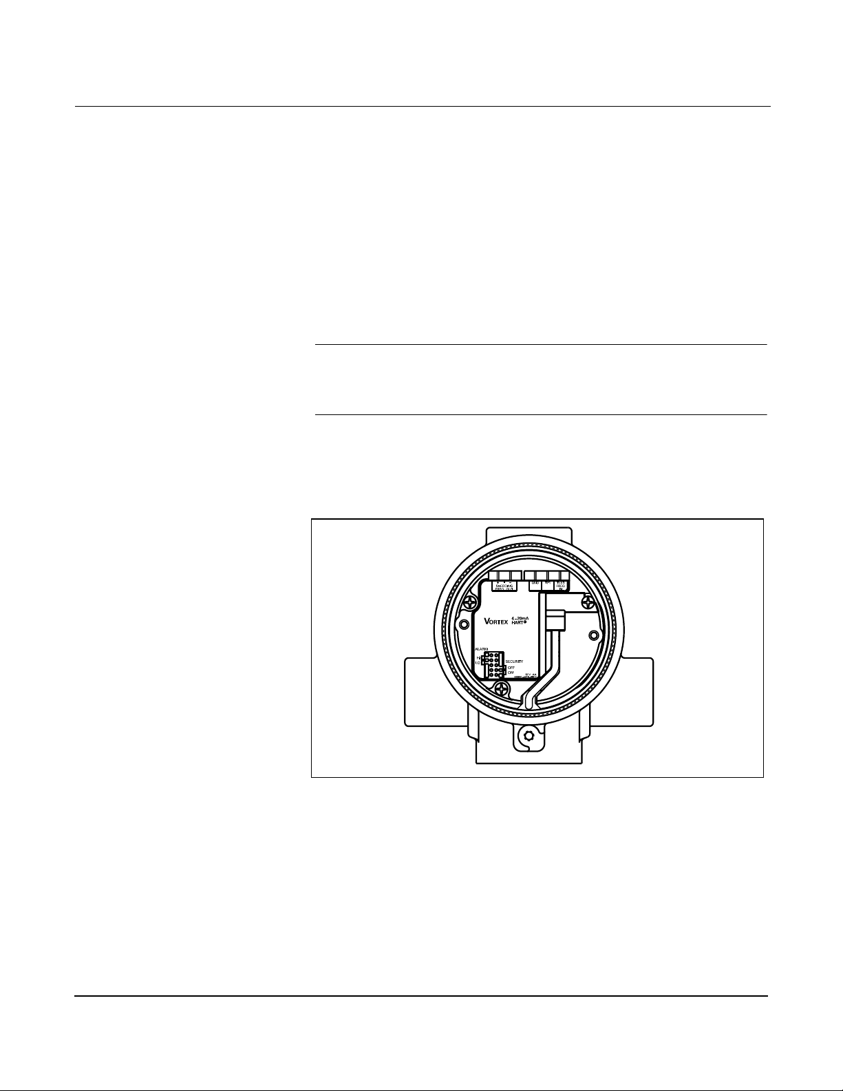
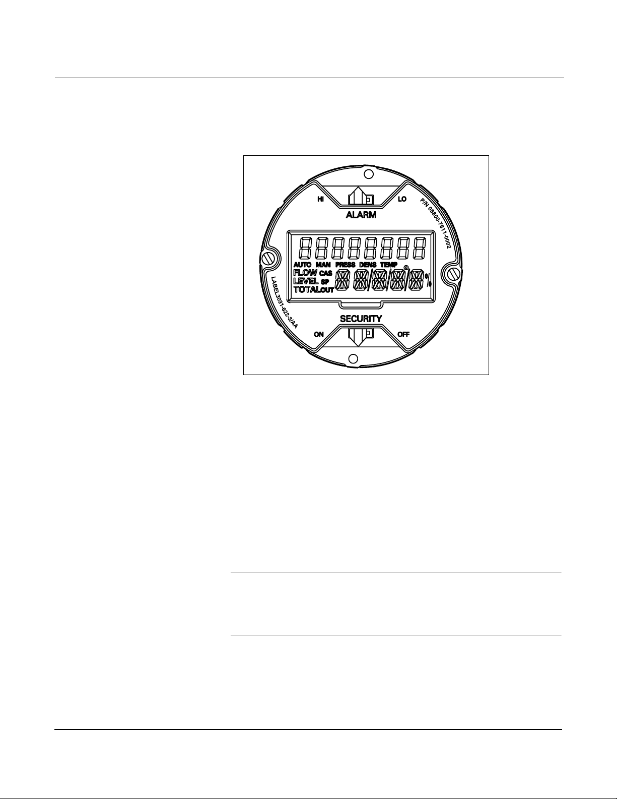
Figure 2-5. Alarm and Security Jumpers
The hardware jumpers on the Model 8800C e nable you to set the alarm
and security. (See Figure 2-5.) To access the jumpers, remove the
electronics housing cover from the end of the Model 8800C. If your
Model 8800C does not include an LCD indicator, the jumpers are
accessible by removing the cover on the electronics side. If your Model
8800C includes an LCD option, the alarm and security jumpers are
found on the face of the LCD indicator. (See Figure 2-6 on page 2-8.)
NOTE
If you will be changing configur ation variables frequently, it may be
useful to leave the security lockout jumper in the OFF position to
avoid exposing the flowmeter electronics to the plant environment.
Set these jumpers during the commissioning stage to avoid exposing
the electroni cs to the plant environment.
2-6
8800-0000A04C
Page 17
Installation
Alarm
As part of normal operations , the Model 8800C continuously runs a
self-diagnostic routine. If the routine detects an internal failure in the
electr on ics, flowme ter output is driven to a low or high alarm leve l,
depending on the pos ition of the failur e mode j umper. The jumper is set
per the CDS; the default setting is HIGH.
The failure mode jumper is labeled ALARM and is set to the high
position at the factory.
Security
You can protect the configurat ion data with the security locko ut jumper.
With the security lockout jumper on, an y configuration changes
attempted on the electronics are disallowed. You can stil l access and
review any of the operating param eters and scroll through the
available c hange s, but no ac tual cha nges wil l be perm itted. The ju mper
is set per C D S ; th e de fa u l t setting is OF F.
Failure Mode vs. Saturation Output Values
The failure mode alarm output levels differ from the output values that
occur when the operating flow is outside the range points. When the
operating flow is outside the range points, the analog output continues
to track the operating flow until reaching the saturation value liste d
below; the output does not exceed the li sted saturati on value regar dless
of the operating flow. F or exam ple , with standard al arm and satur ati on
levels and flows outside the 4—20 mA range points, the output
saturates at 3.9 mA or 20.8 mA. When the tr ansm itter diagnostics
detect a failure, the analog output is set to a specific alarm value that
differs from the saturation value to allow for proper troubleshooting.
.
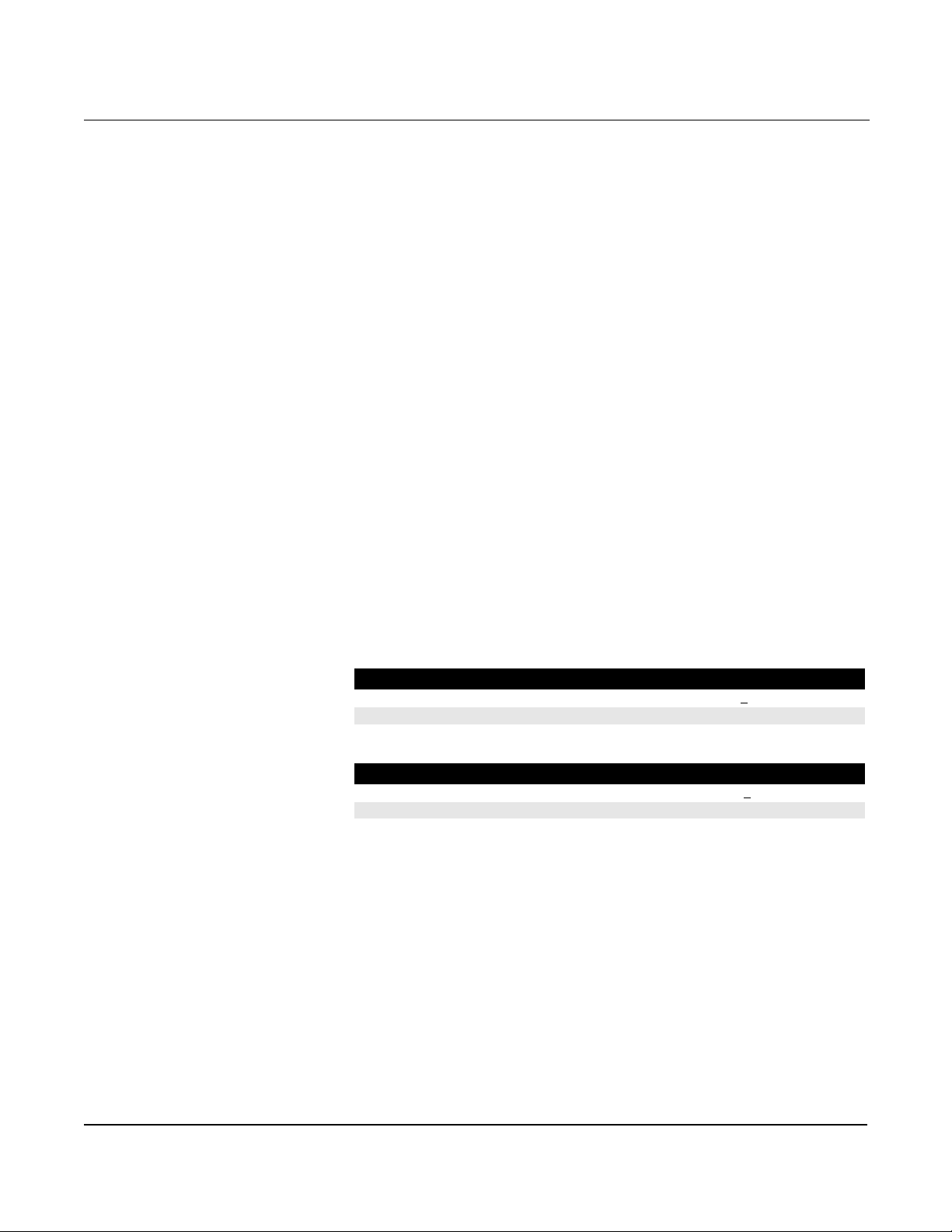
Table 2-1. Analog Output: Standard Alarm Values vs. Saturation Values
Level 4—20 mA Saturation Value 4—20 mA Alarm Value
Low 3.9 mA <
High 20.8 mA >21.75 mA
.
Table 2-2. Analog Output: NAMUR-Compliant Alarm Values vs. Saturation Values
Level 4—20 mA Saturation Value 4—20 mA Alarm Value
Low 3.8 mA <
High 20.5 mA >22.5 m A
3.75 mA
3.6 mA
2-7
Page 18
Rosemount Model 8800C Vortex Flowmeter
LCD Indicator Option If your electronics are equipped with the LCD indicator (Opt ion M5),
the ALARM and SECURITY jumpers are located on the
face of the indicator as shown in Figure 2-6.
Figure 2-6. LCD Indicator Alarm and Security Jumpers
8800-0000B04A
INSTALLATION TASKS The installation tasks include detailed mechanical and electrical
installation procedures.
Handling Handle all parts carefully to prevent damage. Whenever possible,
transport the sy s te m to the insta llation sit e in the ori gi nal ship pi ng
containers. Keep the shipping plugs in the conduit connections until
you are ready to connect and seal them.
Flow Direction Mount the meter body so the FORWARD end of the flow arrow, shown
on the meter body, points in the direction of the flow through the body.
Gaskets The Model 8800C requires gaskets supplied by the user. Be sure to
select gasket ma terial that is compatib le w ith the process fluid and
pressure ratings of the specific installation.
NOTE
Ensure that the inside diame ter of the gasket is larger than the inside
diameter of the flowmeter and adjacent piping. If gasket material
extends into the flow stream, it will disturb the flow and cause
inaccurate measurements.
2-8
Page 19
Installation
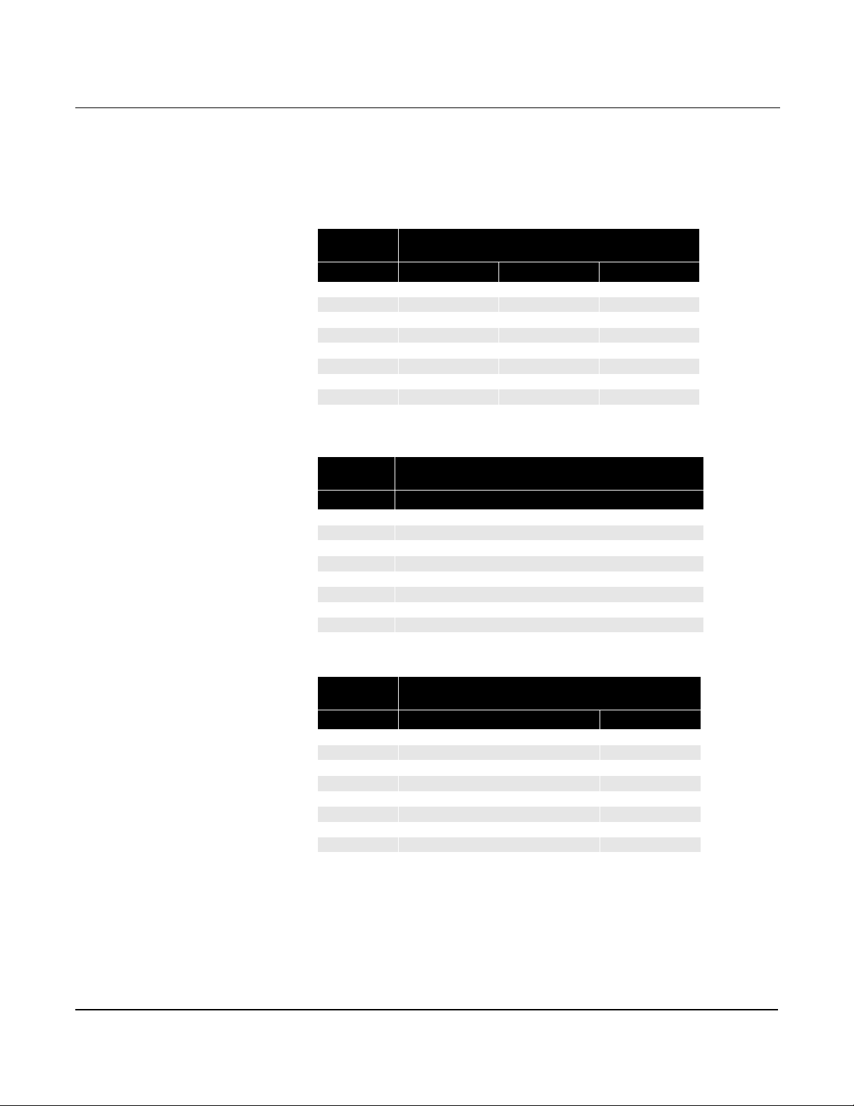
Flange B olts Install the Model 8800C Flowmeter between two conventional pipe
flanges, as shown in Figure 2-7 and Figure 2-8 on page 2-11. Table 2-3,
2-4, and 2-5 lists the recommended minimum stud bolt lengths for
wafer-style meter body size and different flange ratings.
.
Table 2-3. Minimum Recommended Stud Bolt Lengths for Wafer Installation with
ASME B16.5 (ANSI) Flanges
Minimum Recommended Stud Bolt Lengths
(in Inches) for Each Flange Rating
Line Size Class 150 Class 300 Clas s 600
½-inch 6.00 6.25 6.25
1-inch 6.25 7.00 7.50
1½-inch 7.25 8.50 9.00
2-inch 8.50 8.75 9.50
3-inch 9.00 10.00 10.50
4-inch 9.50 10.75 12.25
6-inch 10.75 11.50 14.00
8-inch 12.75 14.50 16.75
T able 2-4. Minimum Recommended Stud Bolt Lengths for
Wafer Ins tal lati on wi th DIN F lan ges
Minimum Recommended Stud Bolt Lengths
(in mm) for Each Flange Rating
Line Size PN 16 PN 40 PN 64 PN 100
DN 15 160 160 170 170
DN 25 160 160 200 200
DN 40 200 200 230 230
DN 50 220 220 250 270
DN 80 230 230 260 280
DN 100 240 260 290 310
DN 150 270 300 330 350
DN 200 320 360 400 420
T able 2-5. Minimum Recommended Stud Bolt Lengths for
Wafer Installation with JIS Flanges
Minimum Recommended Stud Bolt Lengths
(in mm) for Each Flange Rating
Line Size JIS 10k JIS 16k and 20k JIS 40k
15mm 150 155 185
25mm 175 175 190
40mm 195 195 225
50mm 210 215 230
80mm 220 245 265
100mm 235 260 295
150mm 270 290 355
200mm 310 335 410
2-9
Page 20

Rosemount Model 8800C Vortex Flowmeter
Wafer-Style Flowmeter Alignment and Mounting
Center the wafer-style meter body inside diameter with respect to the
inside diameter of the adjoining upstream and downstream pipi ng. This
will ensure that the flowmeter achieves its specified accuracy.
Alignment rings are provided with each wafer-style meter body for
centering purposes. Follow these steps to align the meter body for
installation. Refer to Figure 2-7 on page 2-11.
1. Place the alignment ri ngs over each end of the meter body.
2. Insert the studs for the bottom side of the meter body between
the pipe flanges.
3. Place the meter body (with alignment rings) between the
flanges . Ma ke sure that the alignment rings are properly
placed onto the studs. Align the studs with the markin gs
on the ring that correspond to the flange you are using.
If a spacer is used, see Spacers and Table 2-6 below.
NOTE
Be sure to align the flowmeter so the electronics are accessible, the
conduits drain and the flow m eter is not subject to direct heat.
4. Place the remaining studs between the pipe flanges.
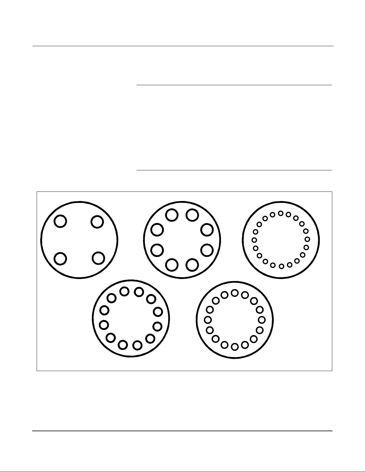
5. Tighten the nuts in the sequence shown in Figure 2-9 on
page 2-12.
6. Check for leaks at the flanges after tightening the flange bolts.
NOTES
The required bolt load for sealing the gasket joint is affected by several
factors , including operati ng pressure and gasket material, width, and
condition. A number of fa ctors also affect the actual bolt load resulting
from a measured torque, including condition of bolt threads, friction
between the nut head and the flange, and parallelism of the flanges.
Due to these application-dependent factors, the required torque for
each applicati on ma y be different. Follow the guidelines outlined
in the ASME Pressure Vessel Code (Section VIII, Division 2) for proper
bolt tig h tening.
Make sure the flowmeter is centered between flanges of the same
nominal size as the flowmet er.
Spacers
Spacers are available with the Model 8800C to maintain the
Model 8800A dimensions. If a spacer is used, it sho uld be downstream
of the meter body. The spacer kit c omes wit h an al ignment ring fo r eas e
of installation. Gaskets should be placed on each side of the spacer.
Table 2-6. Dimensions for Spacers
Line
Size
1.5 (40) 0.47 (11.9)
2 (50) 1.17 (29.7)
3 (80) 1.27 (32.3)
4 (100) 0.97 (24.6)
Dimensions
inch (mm)
2-10
Page 21
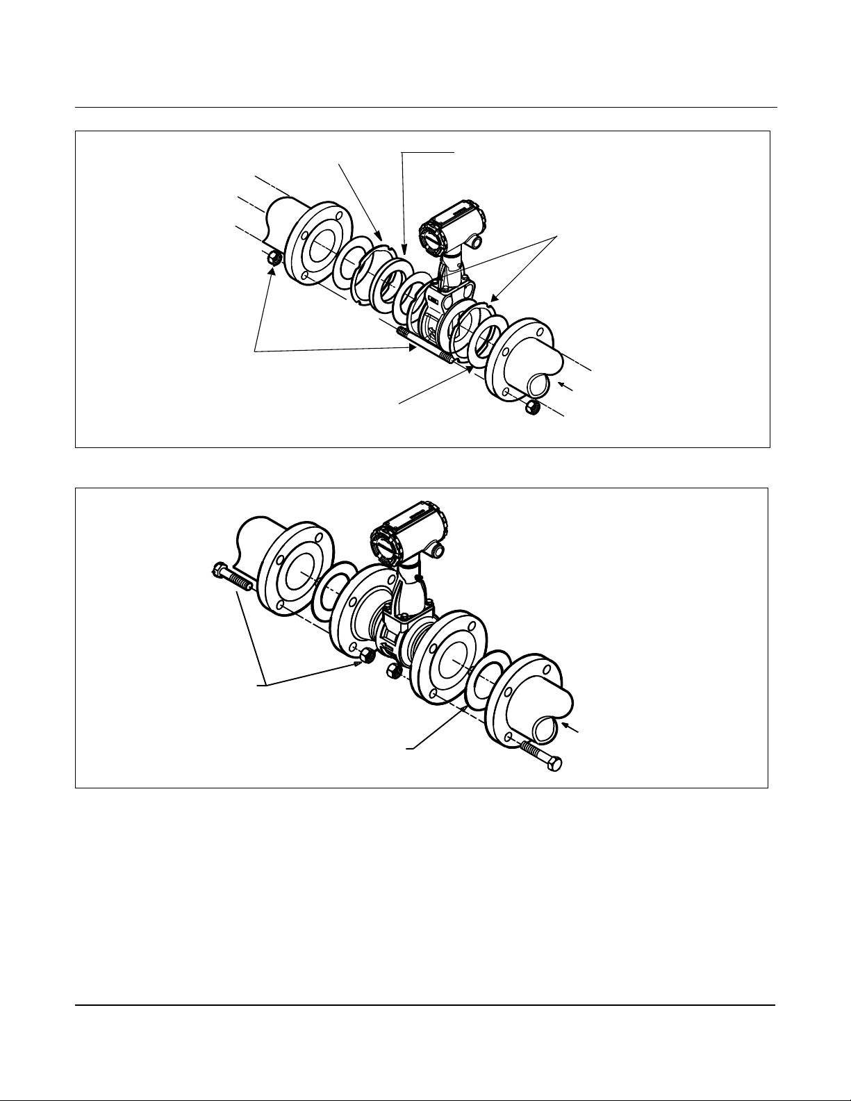
Figure 2-7. Wafer-Style Flowmeter Installation with Alignment Rings
Alignment Ring
Installation Studs and Nuts
(Supplied by Customer)
Installation
Spacer
(for Model 8800C to maintain
Model 8800A dimens ions)
Alignment Rings
(Supplied by Customer)
Figure 2-8. Flanged-Style Flowmeter Installation
Installation Bolts and Nuts
(Supplied by Customer)
Gaskets
(Supplied by Customer)
Gaskets
Flow
8800-0465A01B
Flow
8800-0465A02B
2-11
Page 22
Rosemount Model 8800C Vortex Flowmeter
Flanged-Style Flowmete r M o unting
Figure 2-9. Flange Bolt Torquing Sequence
1
4
3
2
Physical mount ing of a flan ged-style fl owmeter is si milar to i nstalli ng a
typical section of pipe. Conventional tools, equipment, and accessories
(such as bolts and gas kets ) are required . Tig hten the nuts fol lowing t he
sequence shown in Figure 2-9.
NOTE
The required bolt lo ad fo r seali ng the gas ket jo int is aff ec ted b y seve ral
factors , i nclu din g ope ratin g pre ssu re and gasket m ateri al , width , and
conditio n. A number of fac tors al so affec t th e actual bol t load re sul ting
from a measured torque, including condition of bolt threads, friction
between the nut head and the flan ge , and par al leli sm of the fla nges . Due
to these appl icat io n-d epen dent fac to rs , the r equi red to rque for each
application may be different. Follow the guidelines outlined in the ASME
Pressure Vessel Code (Section VIII, D ivi si on 2) for prop er bolt ti ghteni ng.
Make sure the flowmeter is centered between flanges of the same
nominal size as the flowmet er.
8
4
6
2
1
5
3
7
4
12
6
10
20
2
16
17
14
8
18
1
9
5
11
3
19
15
7
13
2-12
4-Bolt
10
8-Bolt
12
2
12-Bolt
11
1
5
9
12
3
7
4
6
10
14
16
8
2
15
16-Bolt
1
9
5
11
3
13
7
8
4
6
20-Bolt
8800-0088A
Page 23

Installation
Flowmete r Gro unding Grounding is not required in typical vortex applications; however, a
good ground will eliminate possible noise pickup by the electronics.
Grounding straps may be used to ensure that the meter is grounded to
the process piping. If you a re us ing the tr ansi ent protect ion option (T1) ,
grounding straps are required to provide a good low impedance ground.
To use grounding straps, secure one end of the grounding strap to the
bolt extending from the side of t he meter body and at tac h the other end
of each grounding strap to a suitable ground.
Electronics Considerations Both integral and remote mounted electronics require input power at
the electroni cs. For remote mount inst allations, mount the electronics
against a flat surface or on a pipe that is up to two inches in diameter.
Remote mounting hardware includes a bracket that is polyurethane
painted carbon steel and one carbon steel u-bolt. See Figure 2-16 on
page 2-24 for dimensional information.
High-Temperature Installations
Install the meter body so the electronics are positioned to the si de of or
below the pipe as shown in Figure 2-2 on page2-4. Insulation may be
required around the pipe to maintain a temperature below
185 °F (85 °C).
Conduit C onnecti o ns The electronics housing has two ports for
connections. Adapters are also available for PG 13.5 or M201.5
conduit. These connections are made in a conventional manner in
accordance with local or plant electrical codes. Be sure to properly seal
unused ports to preve nt moi sture or othe r co ntamina tio n from entering
the terminal block compartment of the electronics housing.
NOTE
In some applications it may be necessary to install conduit seals and
arrange for conduit s to drain to prevent moisture from entering the
wiring compartment.
1
/2–14 NPT conduit
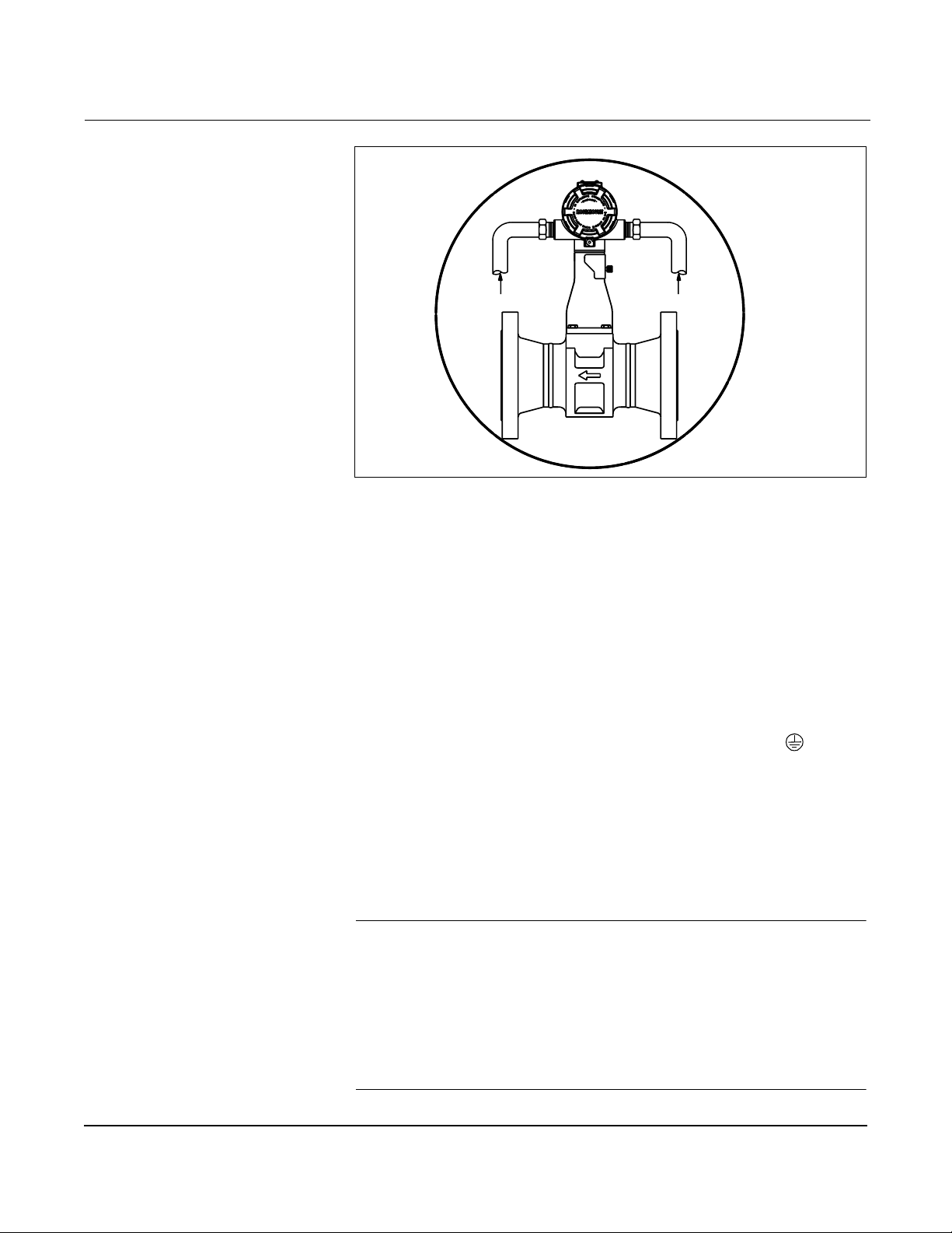
High-Point Installation Prevent condensation in any conduit from flowing into the housing by
mounting the flowmeter at a high point in the conduit run. If the
flowmeter is mounted at a low point in the conduit run, the terminal
compartment could fill with fluid.
If the conduit originates above the flowmeter, route conduit below
the flowmeter before entry. In some cases a drain seal may need to
be installed.
2-13
Page 24
Rosemount Model 8800C Vortex Flowmeter
Figure 2-10. Proper Conduit Installation with Model 8800C
Conduit Line
Conduit Line
Cable Gland If you are using cab le glan d inste ad of conduit , follo w the cabl e gl and
manufacturer’s inst ructi ons for prep aration and make the c onnectio ns in a
convention al man ner in acc or dance w ith lo cal or plant el ectri ca l codes. Be
sure to prope rly sea l unus ed port s to prev ent moist ur e or ot her
contaminati on from en teri ng the termi nal bl oc k comp art ment of the
electronics housing.
Grounding the Transmitter Case
The transmitter case should always be grounded in accordance with
national and local electrical codes. The most effective transmitter case
grounding method is dire ct connection to earth ground with m inimal
impedance. Methods for grounding the transmitter case include:
• Internal Ground Connection: The Internal Ground Connection
screw is inside the FIELD TERMINALS side of the electronics
housing. This screw is identified by a ground symbol (
), and is
standard on all Model 8800C transmitters.
• External Ground Assembly: This assembly is included with the
optional transient protection terminal block (Option Code T1),
and it is included with KEMA/CENELEC Flameproof
Certification (Option Code ED), BASEEFA/CENELEC Intrinsic
Safety Certification (Option Code I1), and BASEEFA Type N
Certification (Option Code N1). The External Ground Assembly
can also be ordered with the transmitter (Option Code V5).
8800-000A02B
2-14
NOTE
Grounding the transmitt er case using the threaded conduit connection
may not provide a sufficient ground. The transient protection terminal
block (Option Code T1) doe s not provi de tr ansient pr ote ction unl ess t he
transmitter case is properly grounded. See Transient Protection on
page 2-36 for transient terminal bloc k grounding. Use the above
guidelines to gro und the transmitter case. Do not run the transient
protection ground w ire with signal wiring as the grou nd wire ma y carry
excessive current if a lightning strike occurs.
Page 25
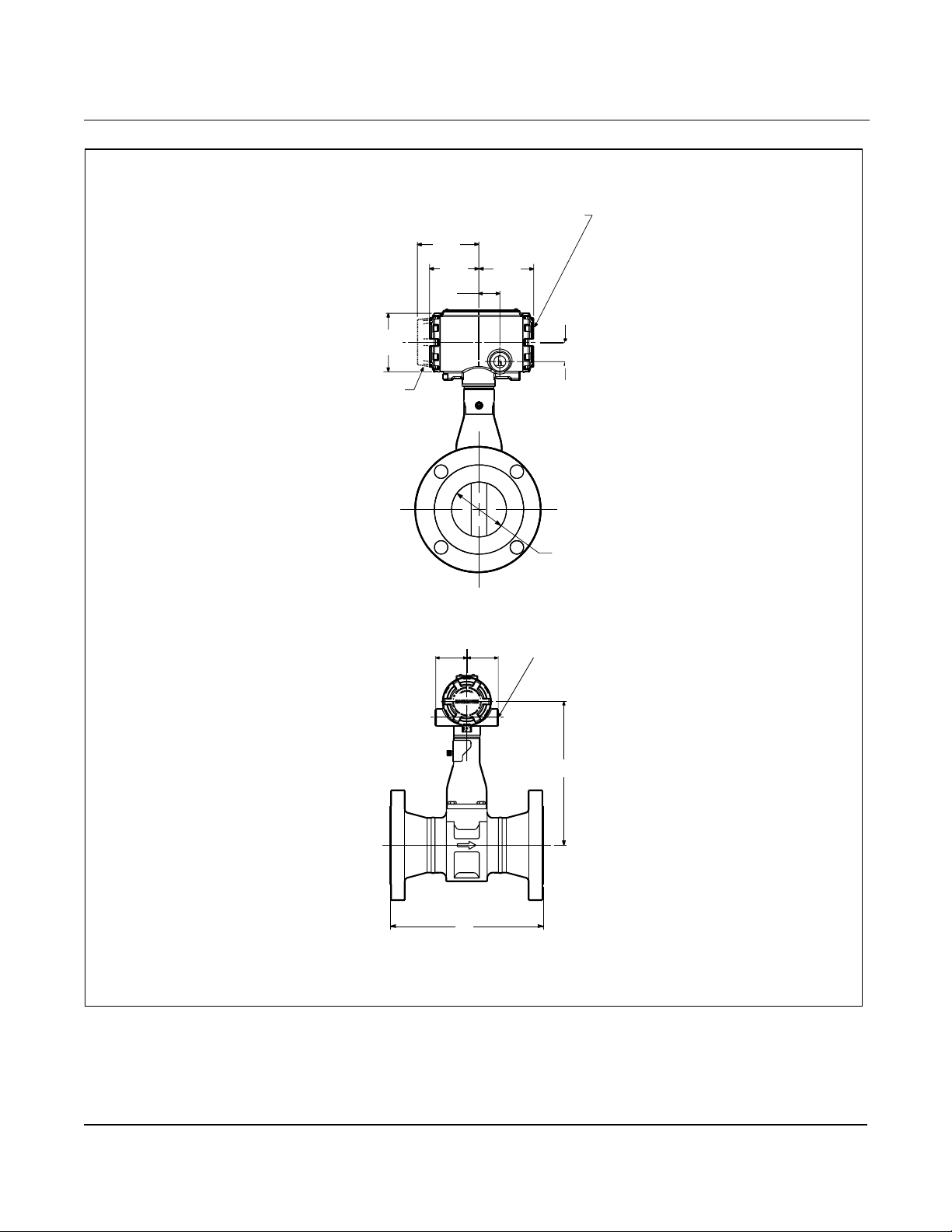
Figure 2-11. Flanged-Style Flowmeter Dimensional Drawings (1/2- through 12-in./15 through 300 mm Line Sizes)
Terminal Cover
3.20
(81)
2.56
(65)
1.10
(28)
2.85
(72)
Installation
Diameter
3.06 (78)
Displ ay Op t ion
2.00
(51)
2.00
(51)
1.00
(25)
Diameter B
Electrical Connection ASME
B16.5 (ANSI) ½–14 NPT (2 places)
C
NOTE
Dimensions are in inches (millimeters)
A
8800-0002A02B, 0002B02B
2-15
Page 26
Rosemount Model 8800C Vortex Flowmeter
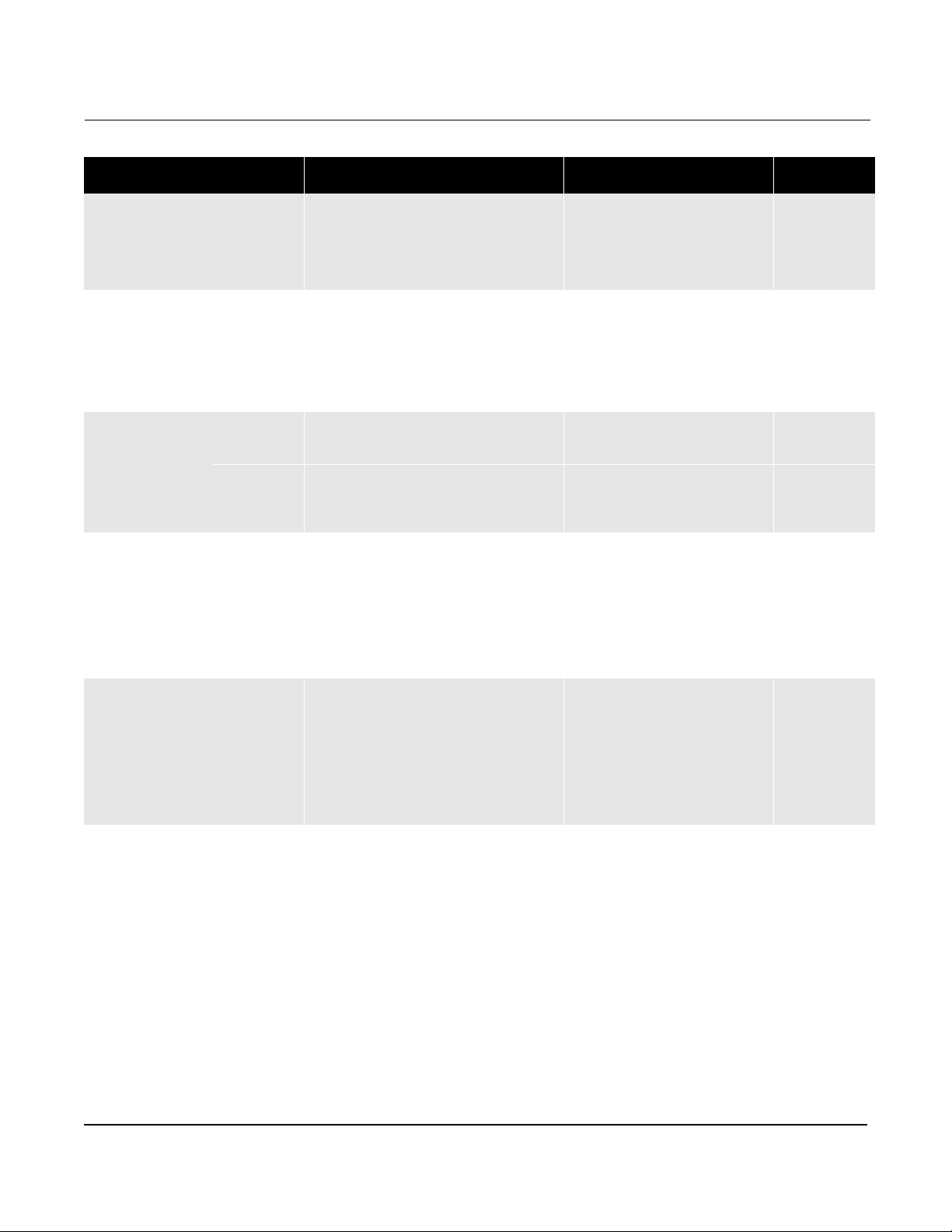
Table 2-7. Flanged-Style Flowmeter (1/2-through 3-in./ 15 through 80 mm Line Sizes)
Nominal Size
Inch (mm )
½ (15) Class 150
1 (25) Class 150
1 ½ (40) Cl ass 150
2 (50) Class 150
3 (80) Class 150
(1) ±0.14 inch (3.6 mm)
(2) ±0.03 inch (0.8 mm)
(3) ±0.20 inch (5.1 mm)
(4) Add 0.2 lb (0,1 kg) for display option.
Flange
Rating
Class 300
Class 600
PN 16/40
PN 100
JIS 10K/20K
JIS 40K
Class 300
Class 600
Class 900
PN 16/40
PN 100
PN 160
JIS 10K/20K
JIS 40K
Class 300
Class 600
Class 900
PN 16/40
PN 100
PN 160
JIS 10K/20K
JIS 40K
Class 300
Class 600
Class 900
PN 16/40
PN 64
PN 100
PN 160
JIS 10K
JIS 20K
JIS 40K
Class 300
Class 600
Class 900
PN 16/40
PN 64
PN 100
PN 160
JIS 10K
JIS 20K
JIS 40K
Face-to-face A
Inch (mm)
6.9 (175)
7.2 (183)
7.7 (196)
6.1 (155)
6.6 (168)
6.3 (160)
7.3 (185)
7.5 (191)
8.0 (203)
8.5 (216)
9.4 (239)
6.3 (160)
7.7 (195)
7.7 (195)
6.5 (165)
7.9 (200)
8.2 (208)
8.7 (221)
9.4 (239)
10.4 (264)
6.9 (175)
8.2 (208)
8.4 (213)
7.3 (185)
8.5 (215)
9.3 (236)
9.8 (249)
10.5 (267)
12.8 (325)
8.0 (203)
9.2 (234)
9.6 (244)
10.2 (259)
7.7 (195)
8.3 (210)
9.8 (249)
9.9 (251)
10.6 (269)
11.4 (290)
12.9 (328)
8.9 (226)
10.0 (254)
10.5 (267)
11.2 (284)
7.9 (200)
9.3 (235)
11.0 (280)
(1)
A-ANSI RTJ
Inch (mm)
–
7.7 (196)
7.7 (196)
–
–
–
–
8.0 (203)
8.5 (216)
8.5 (216)
9.4 (239)
–
–
–
–
–
8.7 (221)
9.2 (234)
9.4 (239)
10.4 (264)
–
–
–
–
–
9.8 (249)
10.4 (264)
10.7 (271)
12.9 (328)
–
–
–
–
–
–
–
10.4 (264)
11.2 (284)
11.5 (292)
13.0 (330)
–
–
–
–
–
–
–
Diameter B
Inch (mm )
0.52 (13,2)
0.52 (13,2)
0.52 (13,2)
0.52 (13,2)
0.52 (13,2)
0.52 (13,2)
0.52 (13,2)
0.95 (24,1)
0.95 (24,1)
0.95 (24,1)
0.95 (24,1)
0.95 (24,1)
0.95 (24,1)
0.95 (24,1)
0.95 (24,1)
0.95 (24,1)
1.49 (37,8)
1.49 (37,8)
1.49 (37,8)
1.49 (37,8)
1.49 (37,8)
1.49 (37,8)
1.49 (37,8)
1.49 (37,8)
1.49 (37,8)
1.92 (48,8)
1.92 (48,8)
1.92 (48,8)
1.92 (48,8)
1.92 (48,8)
1.92 (48,8)
1.92 (48,8)
1.92 (48,8)
1.92 (48,8)
1.92 (48,8)
1.92 (48,8)
2.87 (72,9)
2.87 (72,9)
2.87 (72,9)
2.87 (72,9)
2.87 (72,9)
2.87 (72,9)
2.87 (72,9)
2.87 (72,9)
2.87 (72,9)
2.87 (72,9)
2.87 (72,9)
(2)
C
Inch (mm)
7.6 (193 )
7.6 (193 )
7.6 (193 )
7.6 (193 )
7.6 (193 )
7.6 (193 )
7.6 (193 )
7.7 (196 )
7.7 (196 )
7.7 (196 )
7.7 (196 )
7.7 (196 )
7.7 (196 )
7.7 (196 )
7.7 (196 )
7.7 (196 )
8.1 (206 )
8.1 (206 )
8.1 (206 )
8.1 (206 )
8.1 (206 )
8.1 (206 )
8.1 (206 )
8.1 (206 )
8.1 (206 )
8.5 (216 )
8.5 (216 )
8.5 (216 )
8.5 (216 )
8.5 (216 )
8.5 (216 )
8.5 (216 )
8.5 (216 )
8.5 (216 )
8.5 (216 )
8.5 (216 )
9.1 (231 )
9.1 (231 )
9.1 (231 )
9.1 (231 )
9.1 (231 )
9.1 (231 )
9.1 (231 )
9.1 (231 )
9.1 (231 )
9.1 (231 )
9.1 (231 )
(4)
Weight
(3)
10.4 (4,7)
10.8 (4,9)
10.4 (4,7)
12.3 (5,6)
10.1 (4,5)
13.5 (6,1)
12.3 (5,6)
15.0 (6,8)
15.8 (7,2)
24.3 (11,0)
13.5 (6,1)
19.5 (8,8)
19.5 (8,8)
13.7 (6,2)
17.4 (7,9)
17.6 (8,0)
23.0 (10,4)
25.3 (11,5)
36.3 (16,5)
19.3 (8,8)
27.9 (12,7)
29.3 (13,3)
18.6 (8,4)
25.6 (11,6)
22.0 (10,0)
26.0 (11,8)
29.6 (13,4)
59.4 (26,9)
23.0 (10,4)
30.6 (13,9)
36.4 (16,5)
38.7 (17,6)
19.5 (8,8)
20.1 (9,1)
28.3 (12,8)
36.9 (16,7)
46.1 (20,9)
52.1 (26,6)
75.5 (34,2)
36.3 (16,5)
45.1 (20,5)
54.4 (24,7)
59.6 (27,0)
27.6 (12,5)
35.0 (15,9)
50.0 (22,7)
lb (kg)
9.1 (4,1)
2-16
Page 27
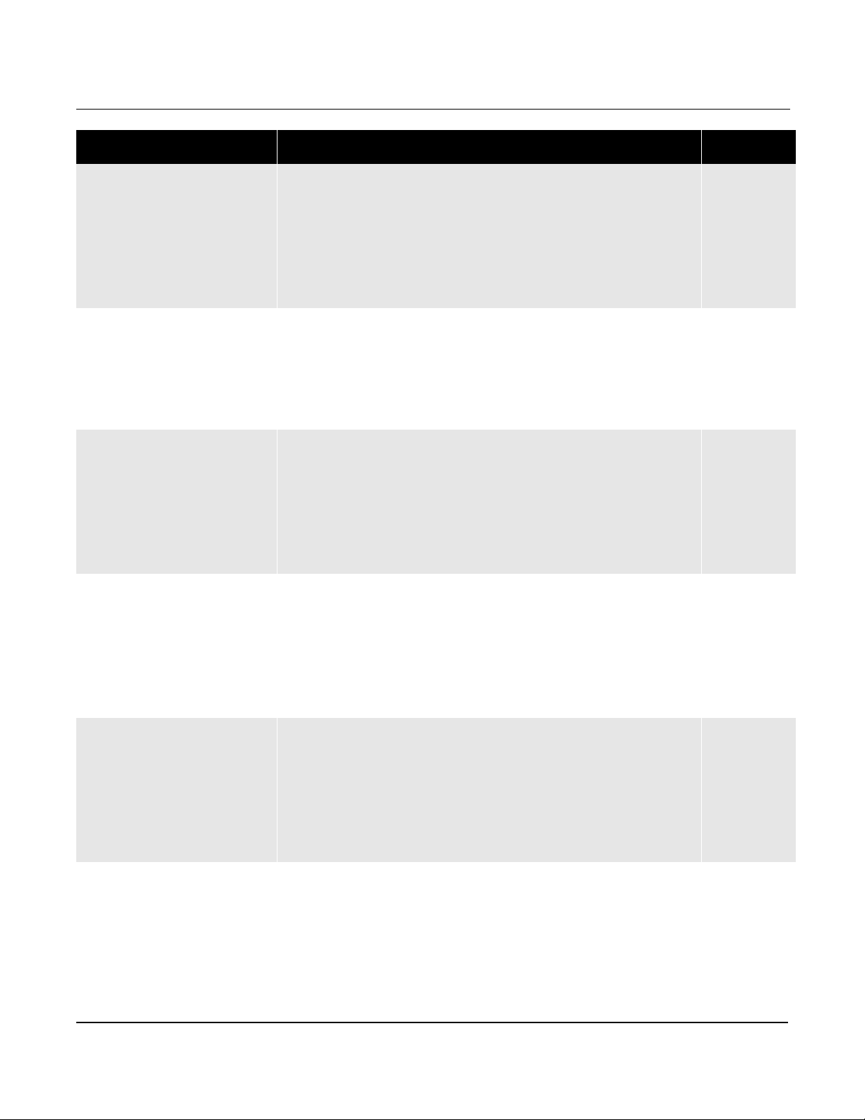
Table 2-8. Flanged-Style Flowmeter (4-through 12-in./ 100 through 300mm Line Sizes) (Refer to Figure 2-11)
Nominal Size
Inch (mm)
4 (100) Cla ss 150
6 (150) Class 150
8 (200) Cla ss 150
10 (250) Class 150
12 (300) Class 150
(1) ±0.14 inch (3.6 mm)
(2) ±0.03 inch (0.8 mm)
(3) ±0.20 inch (5.1 mm)
(4) Add 0.2 lb (0,1 kg) for display option.
Flange
Rating
Class 300
Class 600
Class 900
PN 16
PN 40
PN 64
PN 100
PN 160
JIS 10K
JIS 20K
JIS 40K
Class 300
Class 600
PN 16
PN 40
PN 64
PN 100
JIS 10K
JIS 20K
JIS 40K
Class 300
Class 600
PN 10
PN 16
PN 25
PN 40
PN 64
PN 100
JIS 10K
JIS 20K
JIS 40K
Class 300
Class 600
PN 10
PN 16
PN 25
PN 40
PN 64
PN 100
JIS 10K
JIS 20K
JIS 40K
Class 300
Class 600
PN 10
PN 16
PN 25
PN 40
PN 64
PN 100
JIS 10K
JIS 20K
JIS 40K
Face-to-face A
Inch (mm)
10.3 (262 )
11.0 (279 )
12.8 (325 )
13.8 (351 )
10.4 (264 )
11.3 (287 )
12.1 (307 )
11.8 (300 )
11.6 (295 )
12.4 (315 )
14.3 (363 )
10.5 (267 )
12.1 (307 )
13.7 (348 )
10.6 (270 )
10.6 (270 )
14.2 (360 )
13.6 (345 )
14.3 (363 )
16.6 (422 )
10.5 (266 )
10.5 (266 )
11.9 (302 )
12.5 (318 )
14.2 (361 )
15.8 (401 )
12.2 (310 )
12.2 (310 )
16.5 (420 )
14.6 (371 )
15.8 (401 )
19.1 (485 )
11.9 (302 )
12.1 (307 )
13.5 (343 )
14.8 (376 )
16.4 (417 )
18.9 (480 )
14.6 (371 )
14.6 (371 )
18.1 (460 )
16.8 (427 )
18.0 (457 )
20.5 (521 )
13.2 (335 )
13.9 (353 )
15.0 (381 )
16.9 (429 )
18.8 (478 )
21.2 (538 )
15.7 (399 )
15.7 (399 )
19.7 (500 )
8.4 (213)
9.4 (239)
8.7 (220)
8.7 (220)
8.9 (226)
(1)
A ANSI RTJ
Inch (mm)
10.8 (274 )
11.6 (295 )
12.9 (328 )
13.9 (353 )
–
–
–
–
–
–
–
–
12.1 (307 )
13.0 (330 )
14.5 (368 )
–
–
–
–
–
–
–
14.1 (358 )
15.0 (381 )
16.7 (424 )
–
–
–
–
–
–
–
–
–
15.1 (384 )
16.4 (417 )
19.2 (488 )
–
–
–
–
–
–
–
–
–
17.3 (439 )
18.7 (475 )
20.7 (526 )
–
–
–
–
–
–
–
–
–
Diamet e r B
Inch (mm)
3.79 (96,3)
3.79 (96,3)
3.79 (96,3)
3.79 (96,3)
3.79 (96,3)
3.79 (96,3)
3.79 (96,3)
3.79 (96,3)
3.79 (96,3)
3.79 (96,3)
3.79 (96,3)
3.79 (96,3)
5.7 (144,8)
5.7 (144,8)
5.7 (144,8)
5.7 (144,8)
5.7 (144,8)
5.7 (144,8)
5.7 (144,8)
5.7 (144,8)
5.7 (144,8)
5.7 (144,8)
7.55 (191 ,8)
7.55 (191 ,8)
7.55 (191 ,8)
7.55 (191 ,8)
7.55 (191 ,8)
7.55 (191 ,8)
7.55 (191 ,8)
7.55 (191 ,8)
7.55 (191 ,8)
7.55 (191 ,8)
7.55 (191 ,8)
7.55 (191 ,8)
9.56 (243)
9.56 (243)
9.56 (243)
9.56 (243)
9.56 (243)
9.56 (243)
9.56 (243)
9.56 (243)
9.56 (243)
9.56 (243)
9.56 (243)
9.56 (243)
11.38 (2 89)
11.38 (2 89)
11.38 (2 89)
11.38 (2 89)
11.38 (2 89)
11.38 (2 89)
11.38 (2 89)
11.38 (2 89)
11.38 (2 89)
11.38 (2 89)
11.38 (2 89)
11.38 (2 89)
(2)
C
Inch (mm)
9.6 (244)
9.6 (244)
9.6 (244)
9.6 (244)
9.6 (244)
9.6 (244)
9.6 (244)
9.6 (244)
9.6 (244)
9.6 (244)
9.6 (244)
9.6 (244)
10.8 (274 )
10.8 (274 )
10.8 (274 )
10.8 (274 )
10.8 (274 )
10.8 (274 )
10.8 (274 )
10.8 (274 )
10.8 (274 )
10.8 (274 )
11.7 (297 )
11.7 (297 )
11.7 (297 )
11.7 (297 )
11.7 (297 )
11.7 (297 )
11.7 (297 )
11.7 (297 )
11.7 (297 )
11.7 (297 )
11.7 (297 )
11.7 (297 )
12.8 (325 )
12.8 (325 )
12.8 (325 )
12.8 (325 )
12.8 (325 )
12.8 (325 )
12.8 (325 )
12.8 (325 )
12.8 (325 )
12.8 (325 )
12.8 (325 )
12.8 (325 )
13.7 (348 )
13.7 (348 )
13.7 (348 )
13.7 (348 )
13.7 (348 )
13.7 (348 )
13.7 (348 )
13.7 (348 )
13.7 (348 )
13.7 (348 )
13.7 (348 )
13.7 (348 )
(3)
Installation
(4)
Weight
lb (kg)
50.7 (23,0)
70.8 (32,1)
96.5 (43,8)
119.7 (54,3)
40.1 (18,2)
49.2 (22,3)
62.1 (28,2)
78.5 (35,6)
85.8 (38,9)
37.0 (16,8)
44.9 (20,4)
75.3 (34,2)
90.0 (40,8)
129.5 (58,7)
195.5 (88,7)
75.6 (34,3)
95.3 (43,2)
138.8 (63,0)
168.5 (76,4)
79.8 (36,2)
97.7 (44,3)
175.9 (79,8)
139.6 (63,3)
196.2 (89,0)
295.0 (133,8)
109.6 (49,7)
108.5 (49,2)
136.3 (61,8)
154.8 (70,2)
214.6 (97,3)
279.9 (127)
109.9 (49,9)
134.3 (60,9)
255.7 (116)
197.2 (89)
285.2 (129)
475.3 (216)
156.3 (71)
161.1 (73)
197.4 (90)
245.3 (111)
306.3 (139)
443.0 (201)
173.3 (79)
220.5 (100)
377.3 (171)
296.0 (134)
413.2 (187)
592.2 (269)
203.1 (92)
223.4 (101)
267.8 (121)
345.7 (157)
428.5 (194)
640.8 (291)
224.5 (102)
287.1 (130)
504.7 (229)
2-17
Page 28
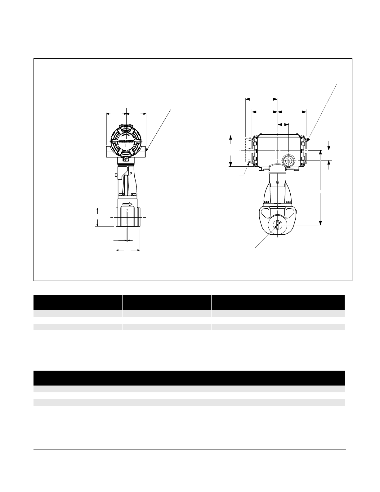
Rosemount Model 8800C Vortex Flowmeter
Figure 2-12. Wafer-Style Dimensional Drawings (1/2-through 11/2 in./15 through 40 mm Line Sizes)
Terminal Cover
Electrical Connection
ASME B16.5 (ANSI)
1
2.00
(51)
/2-14 NPT (2 places)
2.00
(51)
Diameter D
E
A
NOTE
Dimensions are in inches (millimeters)
Electronics housing may be rotated in 90 degree increments
Diameter
3.06 (78)
Display
Option
3.20
(81)
2.56
(65)
1.10
(28)
Diameter B
2.85
(72)
1.00
(25)
C
8800-002D01D, 002C01C
Table 2-9. Model 8800C Stainless Steel Wafer
Nominal Size
Inch (mm)
½ (15) 2.56 (65) 0.54 (13,7) 7.63 (194) 1.38 (35,1) 0.23 (5,9) 7.3 (3,3)
1 (25) 2.56 (65) 0.95 (24,1) 7.74 (197) 1.98 (50,3) 0.23 (5,9) 7.4 (3,4)
1½ (40) 2.56 (65) 1.49 (37,8) 8.14 (207) 2.87 (72,9) 0.18 (4,6) 10 .0 (4,5)
(1) ±0.14 inch (3.6 mm)
(2) ±0.03 inch (0.8 mm)
(3) ±0.20 inch (5.1 mm)
(4) Add 0.2 lb (0,1 kg) for display option.
Face-to-face A
Inch (mm)
(1)
Diameter B
Inch (mm )
(2)
C
Inch (mm)
(3)
Diameter D
Inch (mm)
E
Inch (mm)
Table 2-10. Model 8800A Hastelloy© Wafer
Nominal Size
Inch (mm )
½ (15) 2.44 (62) 0.52 (13,2) 7.63 (194) 1.38 (35,1) 0.17 (4,3) 6.8 (3,1)
1 (25) 2.44 (62) 0.95 (24,1) 7.74 (197) 1.98 (50,3) 0.17 (4,3) 7.6 (3,4)
1½ (40) 3.11 (79) 1.49 (37,8) 8.08 (205) 2.87 (72,9) 0.47 (11,9) 10.8 (4,9)
(1) ±0.14 inch (3.6 mm)
(2) ±0.03 inch (0.8 mm)
(3) ±0.20 inch (5.1 mm)
(4) Add 0.2 lb (0,1 kg) for display option.
Face-to-face A
Inch (mm)
(1)
Diamet e r B
Inch (mm)
(2)
C
Inch (mm)
(3)
Diameter D
Inch (mm)
E
Inch (mm)
2-18
Weight
lb (kg)
Weight
lb (kg)
(4)
(4)
Page 29
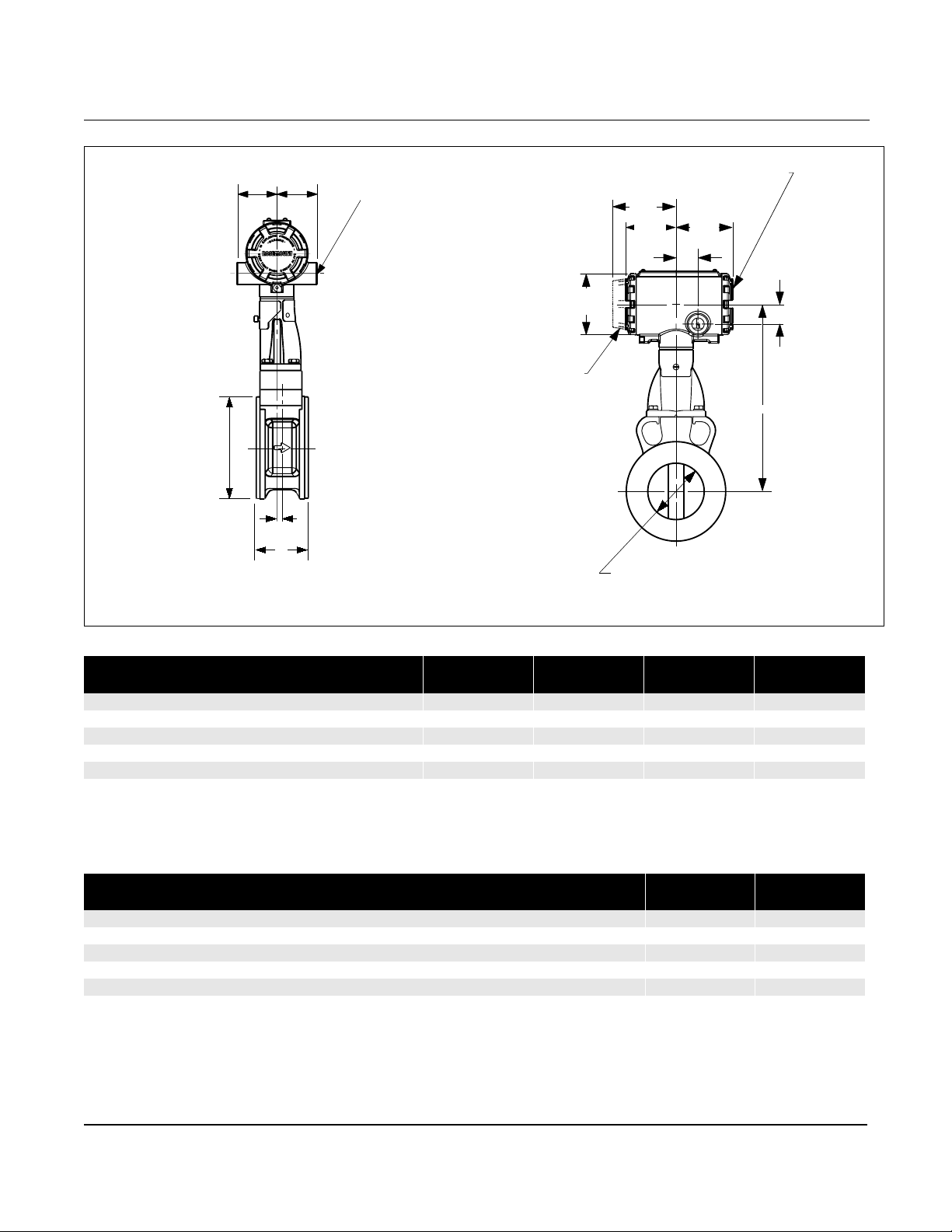
Figure 2-13. Wafer-Style Dimensional Drawings (2-through 8-in./50 through 200 mm Line Sizes)
Installation
Electrical
2.00
(51)
2.00
(51)
Connection ASME
B16.5 (ANSI)
NPT (2 places)
Diameter D
E
A
NOTE
Dimensions are in inches (millimeters)
Electronics housing may be rotated in 90 degree increments
1
/2-14
Diameter
3.06 (78)
Display
Option
3.20
(81)
2.56
(65)
Diameter B
Terminal Cover
2.85
(72)
1.10
(28)
1.00
(25)
C
8800-0002B01C, 0002A01D
Table 2-11. Model 8800C Stainless Steel Wafer
Nominal Size
Inch (mm )
2 (50) 2.56 (65) 1.92 (49) 8.85 (225) 3.86 (98) 0.12 (3) 10.6 (4,8)
3 (80) 2.56 (65) 2.87 (73) 9.62 (244) 5.00 (127) 0.25 (6) 13.6 (6,2)
4 (100) 3.42 (87) 3.79 (96) 10.48 (266) 6.20 (158) 0.44 (11) 21.4 (9,7)
6 (150) 4.99 (127) 5.70 (145) 10.75 (273) 8.50 (216) 1.11 (28) 49.1 (22,3)
8 (200) 6.60 (168) 7.55 (192) 11.67 (296) 10.62 (270) 0.89 (23) 85 (38,6)
(1) ±0.14 inch (3.6 mm)
(2) ±0.03 inch (0.8 mm)
(3) ±0.20 inch (5.1 mm)
(4) Add 0.2 lb (0,1 kg) for display option.
Face-to-face A
Inch (mm)
(1)
Diameter B
Inch (mm)
(2)
C
Inch (mm )
(3)
Diameter D
Inch (mm)
E
Inch (mm)
Table 2-12. Model 8800A Hastelloy© Wafer
Nominal Size
Inch (mm)
2 (50) 3.81 (97) 1.92 (49) 8.45 (215) 3.86 (98) 0.86 (22) 10.8 (4,9)
3 (80) 3.92 (100) 2.87 (73) 9.10 (231) 5.00 (127) 0.76 (19) 15.0 (6,8)
4 (100) 4.47 (114) 3.79 (96) 9.56 (243) 6.20 (158) 0.82 (21) 23.0 (10,4)
6 (150) 4.99 (127) 5.70 (145) 10.75 (273) 8.50 (216) 1.11 (28) 49.1 (22,3)
8 (200) 6.60 (168) 7.55 (192) 11.67 (296) 10.62 (270) 0.89 (23) 85 (38,6)
(1) ±0.14 inch (3.6 mm)
(2) ±0.03 inch (0.8 mm)
(3) ±0.20 inch (5.1 mm)
(4) Add 0.2 lb (0,1 kg) for display option.
Face-to-face A
Inch (mm)
(1)
Diameter B
Inch (mm)
(2)
C
Inch (mm)
(3)
Diameter D
Inch (mm)
E
Inch (mm)
Weight
lb (kg)
Weight
lb (kg)
(4)
(4)
2-19
Page 30
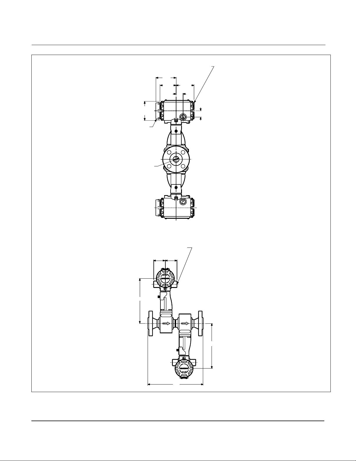
Rosemount Model 8800C Vortex Flowmeter
Figure 2-14. Vortex Dual-Sensor Style Flowmeter Dimensional Drawings (1/2-through 8-in./15 through 200 mm Line Sizes)
Terminal Cover
3.20
(81)
2.56
(65)
1.10
(28)
2.85
(72)
3.06
(78)
Display Option
Diameter B
Electrical Con necti on ASME B 16.5
1
(ANSI)
/2-14 NPT (2 p laces
2.00
(51)
2.00
(51)
1.00
(25)
NOTE
Dimensions are in inches (millimeters)
2-20
C
C
A
8800-0006A01A , 0006B01A
Page 31
Installation
3.20
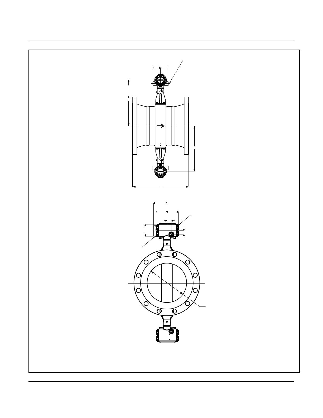
Figure 2-15. Vortex Dual-Sensor Style Flowmeter Dimensional Drawings (10-through 12-in./250 through 300 mm Line Sizes)
2.00
2.00
(51)
(51)
C
A
(81)
2.56
(65)
1.10
(28)
3.06
(78)
Electrical Connection ASME
B16.5 (ANSI)
C
2.85
(72)
Terminal Cover
1.00 (25)
1
/2-14 NPT (2 places)
NOTE
Dimensions are in inches (milli me t ers)
Display Opti o ns
Diameter B
8800-8800c_01, 8800c_02
2-21
Page 32
Rosemount Model 8800C Vortex Flowmeter
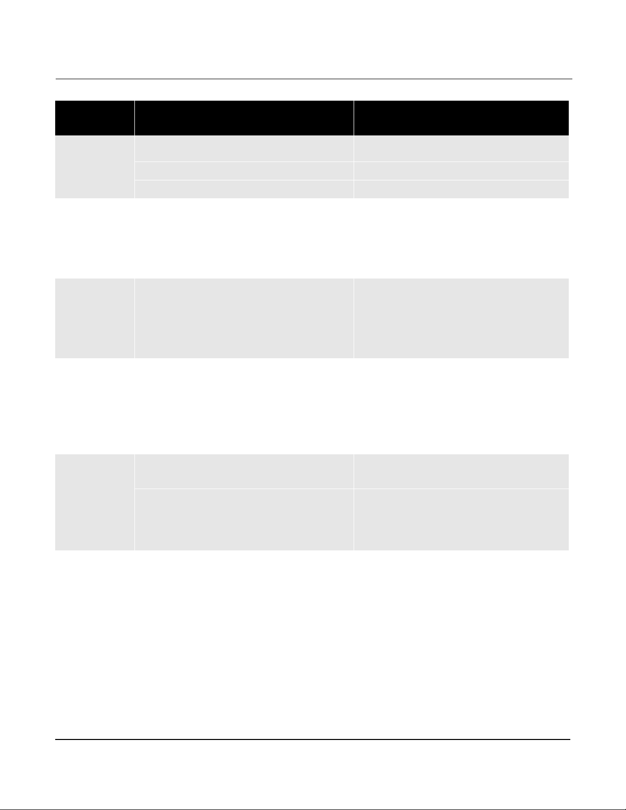
Table 2-13. Vortex Dual-Sensor Style Flowmeter (1/2-through 3-in./15 through 80 mm Line Sizes)
Nominal Size
Inch (mm)
½ (15) Class 150
1 (25) Class 150
1 ½ (40) Class 150
2 (50) Class 150
3 (80) Class 150
(1) ±0.14 inch (3.6 mm)
(2) ±0.03 inch (0.8 mm)
(3) ±0.20 inch (5.1 mm)
(4) Add 0.4 lb (0,2 kg) for display option.
Flange
Rating
Class 300
Class 600
PN 16/40
PN 100
JIS 10K/20K
JIS 40K
Class 300
Class 600
Class 900
PN 16/40
PN 100
PN 160
JIS 10K/20K
JIS 40K
Class 300
Class 600
Class 900
PN 16/40
PN 100
PN 160
JIS 10K/20K
JIS 40K
Class 300
Class 600
Class 900
PN 16/40
PN 64
PN 100
PN 160
JIS 10K
JIS 20K
JIS 40K
Class 300
Class 600
Class 900
PN 16/40
PN 64
PN 100
PN 160
JIS 10K
JIS 20K
JIS 40K
Face-to-face
A
Inch (mm)
12.0 (305)
12.3 (312)
12.8 (325)
11.2 (284)
11.8 (300)
11.4 (290)
12.4 (315)
15.1 (384)
15.6 (396)
16.1 (409)
17.0 (432)
13.9 (353)
15.3 (389)
15.3 (389)
14.1 (358)
15.5 (394)
11.3 (287)
11.8 (300)
12.5 (318)
13.5 (343)
10.0 (254)
11.3 (287)
11.5 (292)
10.4 (264)
11.5 (292)
13.0 (330)
13.6 (345)
14.3 (363)
16.6 (422)
11.8 (300)
12.9 (328)
13.4 (340)
14.0 (356)
11.5 (292)
12.1 (307)
13.6 (345)
14.3 (363)
15.0 (381)
15.8 (401)
17.3 (439)
13.4 (340)
14.5 (367)
14.9 (378)
15.6 (396)
12.3 (312)
13.7 (348)
15.5 (394)
(1)
A
ANSI RTJ
Inch (mm)
–
12.8 (325)
12.8 (325)
–
–
–
–
15.6 (396)
16.1 (409)
16.1 (409)
17.0 (432)
–
–
–
–
–
11.8 (300)
12.3 (312)
12.5 (318)
13.5 (343)
–
–
–
–
–
13.6 (345)
14.1 (358)
14.3 (363)
16.7 (424)
–
–
–
–
–
–
–
14.8 (376)
15.7 (399)
15.8 (401)
17.4 (442)
–
–
–
–
–
–
–
Diameter
B
Inch (mm)
0.52 (13,2)
0.52 (13,2)
0.52 (13,2)
0.52 (13,2)
0.52 (13,2)
0.52 (13,2)
0.52 (13,2)
0.95 (24,1)
0.95 (24,1)
0.95 (24,1)
0.95 (24,1)
0.95 (24,1)
0.95 (24,1)
0.95 (24,1)
0.95 (24,1)
0.95 (24,1)
1.49 (37,8)
1.49 (37,8)
1.49 (37,8)
1.49 (37,8)
1.49 (37,8)
1.49 (37,8)
1.49 (37,8)
1.49 (37,8)
1.49 (37,8)
1.92 (48,8)
1.92 (48,8)
1.92 (48,8)
1.92 (48,8)
1.92 (48,8)
1.92 (48,8)
1.92 (48,8)
1.92 (48,8)
1.92 (48,8)
1.92 (48,8)
1.92 (48,8)
2.87 (72,9)
2.87 (72,9)
2.87 (72,9)
2.87 (72,9)
2.87 (72,9)
2.87 (72,9)
2.87 (72,9)
2.87 (72,9)
2.87 (72,9)
2.87 (72,9)
2.87 (72,9)
(2)
Inch (mm)
C
7.6 (193)
7.6 (193)
7.6 (193)
7.6 (193)
7.6 (193)
7.6 (193)
7.6 (193)
7.7 (196)
7.7 (196)
7.7 (196)
7.7 (196)
7.7 (196)
7.7 (196)
7.7 (196)
7.7 (196)
7.7 (196)
8.1 (206)
8.1 (206)
8.1 (206)
8.1 (206)
8.1 (206)
8.1 (206)
8.1 (206)
8.1 (206)
8.1 (206)
8.5 (216)
8.5 (216)
8.5 (216)
8.5 (216)
8.5 (216)
8.5 (216)
8.5 (216)
8.5 (216)
8.5 (216)
8.5 (216)
8.5 (216)
9.1 (231)
9.1 (231)
9.1 (231)
9.1 (231)
9.1 (231)
9.1 (231)
9.1 (231)
9.1 (231)
9.1 (231)
9.1 (231)
9.1 (231)
(3)
Weight
(4)
lb (kg)
16.2 (7,4)
17.4 (7,9)
17.9 (8,1)
17.2 (7,8)
19.2 (8,7)
17.1 (7,8)
20.6 (9,3)
19.8 (9,0)
22.5 (10,2)
23.3 (10,6)
31.8 (14,4)
21.0 (9,5)
27.0 (12,3)
27.0 (12,3)
22.1 (10,0)
25.8 (11,7)
27.0 (12,3)
32.4 (14,7)
34.8 (15,8)
45.7 (20,7)
28.7 (13,0)
37.4 (17,0)
38.8 (17,6)
27.9 (12,6)
34.9 (15,8)
31.9 (14,5)
35.9 (16,3)
39.5 (17,9)
69.2 (31,4)
32.9 (14,9)
40.5 (18,4)
46.2 (21,0)
48.5 (22,0)
29.1 (13,2)
29.7 (13,5)
37.9 (17,2)
50.3 (22,8)
59.5 (27,0)
65.5 (29,7)
88.9 (40,3)
49.7 (22,5)
58.5 (26,5)
67.8 (30,8)
73.0 (33,1)
41.0 (18,6)
48.4 (22,0)
63.4 (28,8)
2-22
Page 33
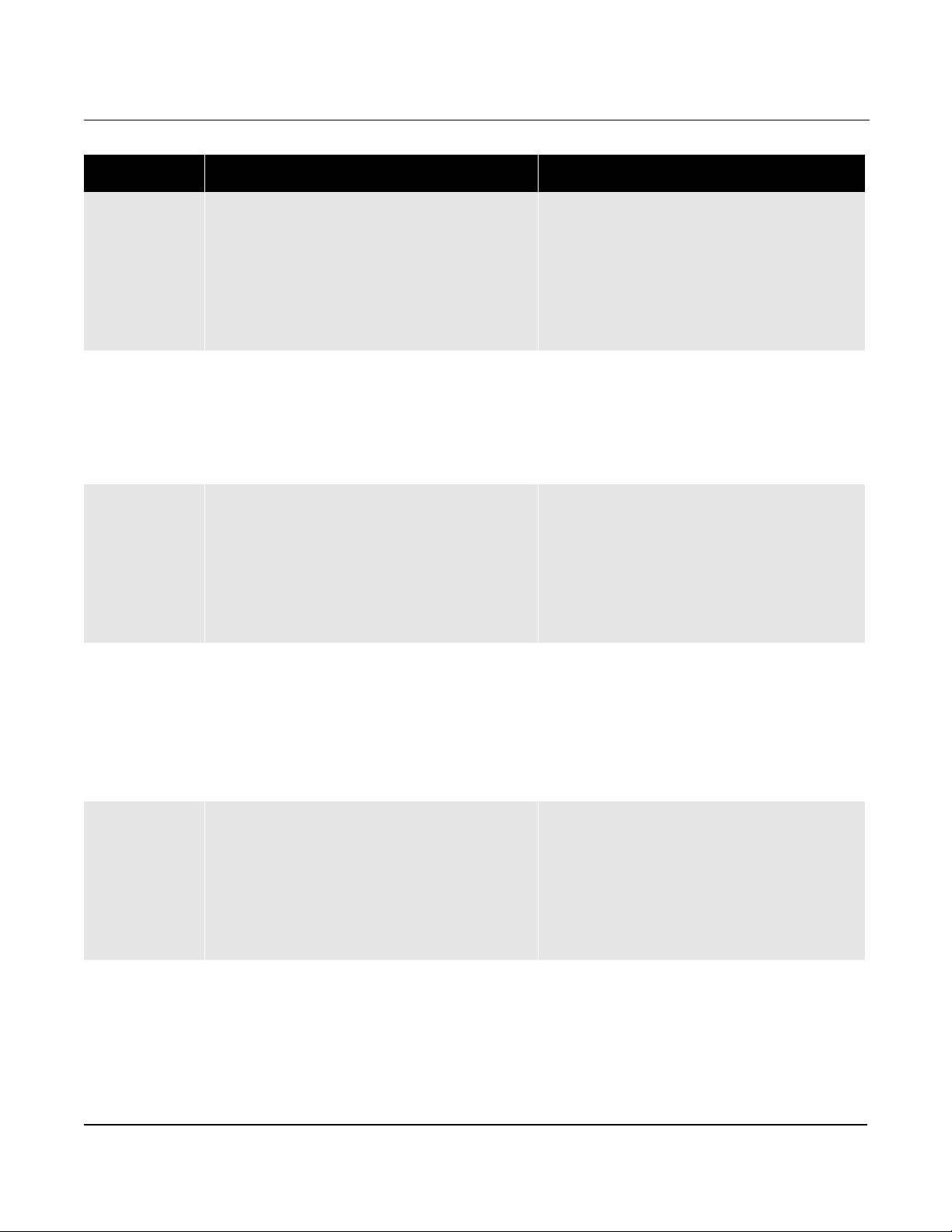
Table 2-14. Vortex Dual-Sensor Style Flowmeter (4- through 12-in./100 through 300 mm Line Sizes)
Nominal Size
Inch (mm)
4 (100) Class 150
6 (150) Class 150
8 (200) Class 150
10 (250) Class 150
12 (300) Class 150
(1) ±0.14 inch (3.6 mm)
(2) ±0.03 inch (0.8 mm)
(3) ±0.20 inch (5.1 mm)
(4) Add 0.4 Lb (0,2 kg) for display option.
Flange
Rating
Class 300
Class 600
Class 900
PN 16
PN 40
PN 64
PN 100
PN 160
JIS 10K
JIS 20K
JIS 40K
Class 300
Class 600
PN 16
PN 40
PN 64
PN 100
JIS 10K
JIS 20K
JIS 40K
Class 300
Class 600
PN 10
PN 16
PN 25
PN 40
PN 64
PN 100
JIS 10K
JIS 20K
JIS 40K
Class 300
Class 600
PN 10
PN 16
PN 25
PN 40
PN 64
PN 100
JIS 10K
JIS 20K
JIS 40K
Class 300
Class 600
PN 10
PN 16
PN 25
PN 40
PN 64
PN 100
JIS 10K
JIS 20K
JIS 40K
Face-to-face A
Inch (mm)
15.2 (386)
16.0 (406)
17.7 (450)
18.7 (475)
13.3 (338)
14.4 (366)
15.4 (391)
16.3 (414)
17.1 (434)
13.6 (345)
13.6 (345)
16.8 (427)
19.4 (493)
20.2 (513)
22.2 (564)
16.8 (427)
18.3 (465)
19.9 (505)
21.5 (546)
18.5 (470)
18.5 (470)
22.0 (559)
24.0 (610)
24.8 (630)
27.0 (686)
20.9 (531)
20.9 (531)
22.3 (566)
22.9 (582)
24.7 (627)
26.3 (668)
22.6 (574)
22.6 (574)
27.0 (686)
14.6 (371)
15.8 (401)
19.1 (485)
11.9 (302)
12.1 (307)
13.5 (343)
14.8 (376)
16.4 (417)
18.9 (480)
14.6 (371)
14.6 (371)
18.1 (460)
16.8 (427)
18.0 (457)
20.5 (521)
13.2 (335)
13.9 (353)
15.0 (381)
16.9 (429)
18.8 (478)
21.2 (538)
15.7 (399)
15.7 (399)
19.7 (500)
(1)
A ANSI RTJ
Inch (mm)
15.7 (399)
16.6 (422)
17.7 (450)
18.9 (480)
–
–
–
–
–
–
–
–
19.9 (505)
20.8 (528)
22.3 (566)
–
–
–
–
–
–
–
24.5 (622)
25.4 (645)
27.1 (688)
–
–
–
–
–
–
–
–
–
15.1 (384)
16.4 (417)
19.2 (488)
–
–
–
–
–
–
–
–
–
17.3 (439)
18.7 (475)
20.7 (526)
–
–
–
–
–
–
–
–
–
Diamet e r B
Inch (mm)
3.79 (96,3)
3.79 (96,3)
3.79 (96,3)
3.79 (96,3)
3.79 (96,3)
3.79 (96,3)
3.79 (96,3)
3.79 (96,3)
3.79 (96,3)
3.79 (96,3)
3.79 (96,3)
3.79 (96,3)
5.7 (144,8)
5.7 (144,8)
5.7 (144,8)
5.7 (144,8)
5.7 (144,8)
5.7 (144,8)
5.7 (144,8)
5.7 (144,8)
5.7 (144,8)
5.7 (144,8)
7.55 (191 ,8)
7.55 (191 ,8)
7.55 (191 ,8)
7.55 (191 ,8)
7.55 (191 ,8)
7.55 (191 ,8)
7.55 (191 ,8)
7.55 (191 ,8)
7.55 (191 ,8)
7.55 (191 ,8)
7.55 (191 ,8)
7.55 (191 ,8)
9.56 (243)
9.56 (243)
9.56 (243)
9.56 (243)
9.56 (243)
9.56 (243)
9.56 (243)
9.56 (243)
9.56 (243)
9.56 (243)
9.56 (243)
9.56 (243)
11.38 (2 89)
11.38 (2 89)
11.38 (2 89)
11.38 (2 89)
11.38 (2 89)
11.38 (2 89)
11.38 (2 89)
11.38 (2 89)
11.38 (2 89)
11.38 (2 89)
11.38 (2 89)
11.38 (2 89)
(2)
C
Inch (mm)
9.6 (244)
9.6 (244)
9.6 (244)
9.6 (244)
9.6 (244)
9.6 (244)
9.6 (244)
9.6 (244)
9.6 (244)
9.6 (244)
9.6 (244)
9.6 (244)
10.8 (274)
10.8 (274)
10.8 (274)
10.8 (274)
10.8 (274)
10.8 (274)
10.8 (274)
10.8 (274)
10.8 (274)
10.8 (274)
11.7 (297)
11.7 (297)
11.7 (297)
11.7 (297)
11.7 (297)
11.7 (297)
11.7 (297)
11.7 (297)
11.7 (297)
11.7 (297)
11.7 (297)
11.7 (297)
12.8 (325)
12.8 (325)
12.8 (325)
12.8 (325)
12.8 (325)
12.8 (325)
12.8 (325)
12.8 (325)
12.8 (325)
12.8 (325)
12.8 (325)
12.8 (325)
13.7 (348)
13.7 (348)
13.7 (348)
13.7 (348)
13.7 (348)
13.7 (348)
13.7 (348)
13.7 (348)
13.7 (348)
13.7 (348)
13.7 (348)
13.7 (348)
Installation
(3)
Weight
(4)
lb (kg)
68.1 (30,9)
88.2 (40,0)
113.9 (51 ,7)
137.1 (62 ,2)
57.6 (26,1)
66.6 (30,2)
79.6 (36,1)
95.9 (43,5)
103.2 (46 ,8)
55.4 (25,1)
63.2 (28,7)
93.7 (42,5)
126.4 (57 ,3)
165.9 (75 ,3)
231.9 (105,2)
112.0 (50 ,8)
131.7 (59 ,7)
175.2 (79 ,5)
204.8 (92 ,9)
124.0 (56 ,2)
141.9 (64 ,4)
220.1 (99 ,8)
190.1 (86 ,2)
246.7 (111,9)
345.5 (156,7)
160.2 (72 ,7)
159.0 (72 ,1)
186.9 (83 ,4)
205.4 (93 ,2)
265.1 (120,2)
330.4 (149,9)
178.2 (80 ,8)
202.6 (91 ,9)
324.0 (147,0)
201.5 (91)
289.5 (131)
479.6 (218)
160.6 (73)
165.4 (75)
210.7 (96)
249.6 (113)
310.6 (141)
447.3 (203)
177.6 (81)
224.8 (102)
381.6 (173)
300.3 (136)
417.5 (189)
596.5 (271)
207.4 (94)
227.7 (103)
272.1 (123)
350.0 (159)
432.8 (196)
645.1 (293)
228.8 (104)
291.4 (132)
508.9 (231)
2-23
Page 34
Rosemount Model 8800C Vortex Flowmeter
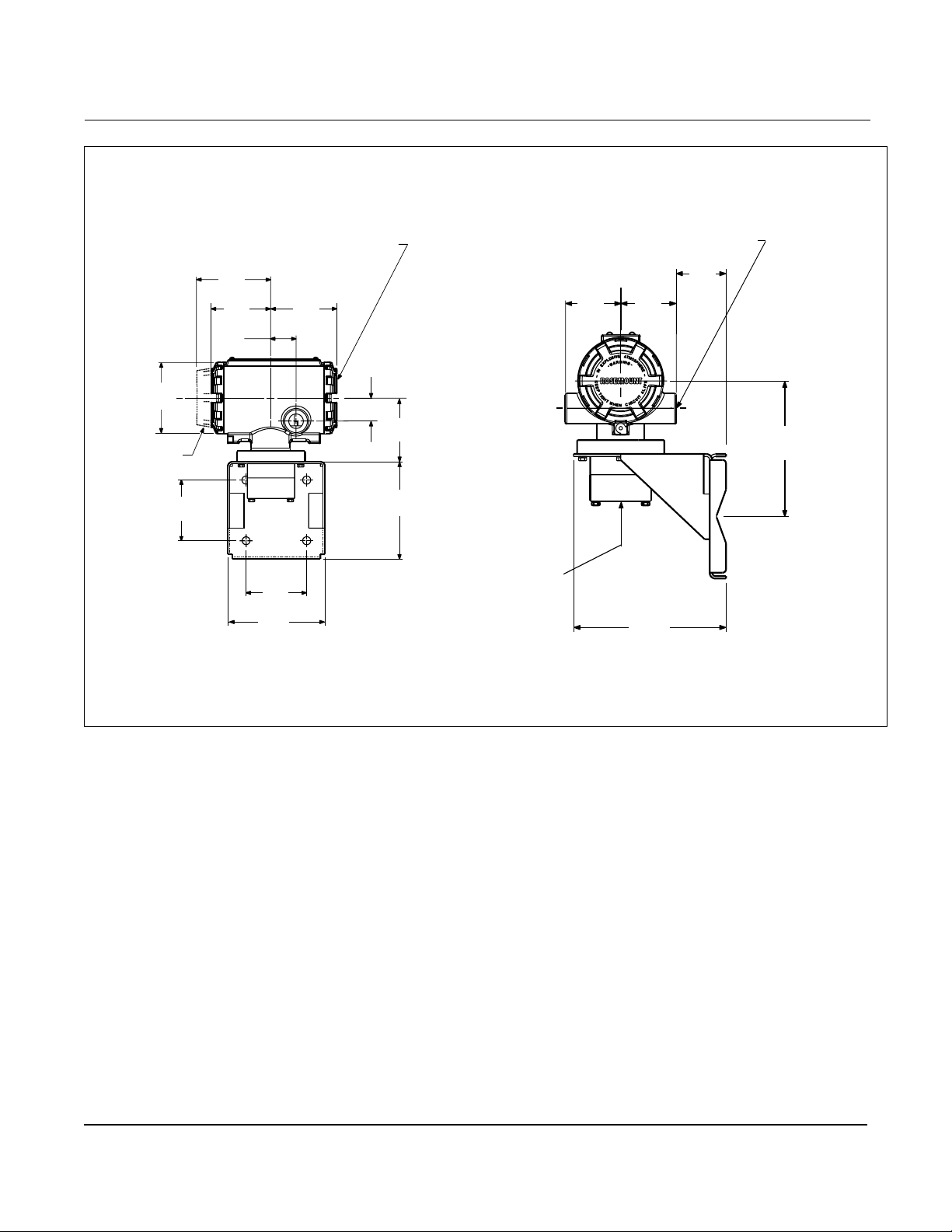
Figure 2-16. Dimensional Drawings for Remote Mount Transmitters
3.06
(78)
Display
Option
2.81
(71)
3.20
(81)
2.56
(65)
1.10
(28)
2.81
(71)
4.50
(114)
Terminal Cover
2.85
(72)
1.00
(25)
2.65
(68)
4.50
(114)
1
/2-14 NPT
(For Remote
Cable
Conduit)
Electrical Co n nection ASME B16.5
1
(ANSI)
/2-14 NPT (2 places)
1.80
(46)
2.00
(51)
2.00
(51)
5.50
(140)
4.90
(124)
NOTE
Dimensions are in inches (millimeters)
8800-0002A04B, 0002B04B
2-24
Page 35
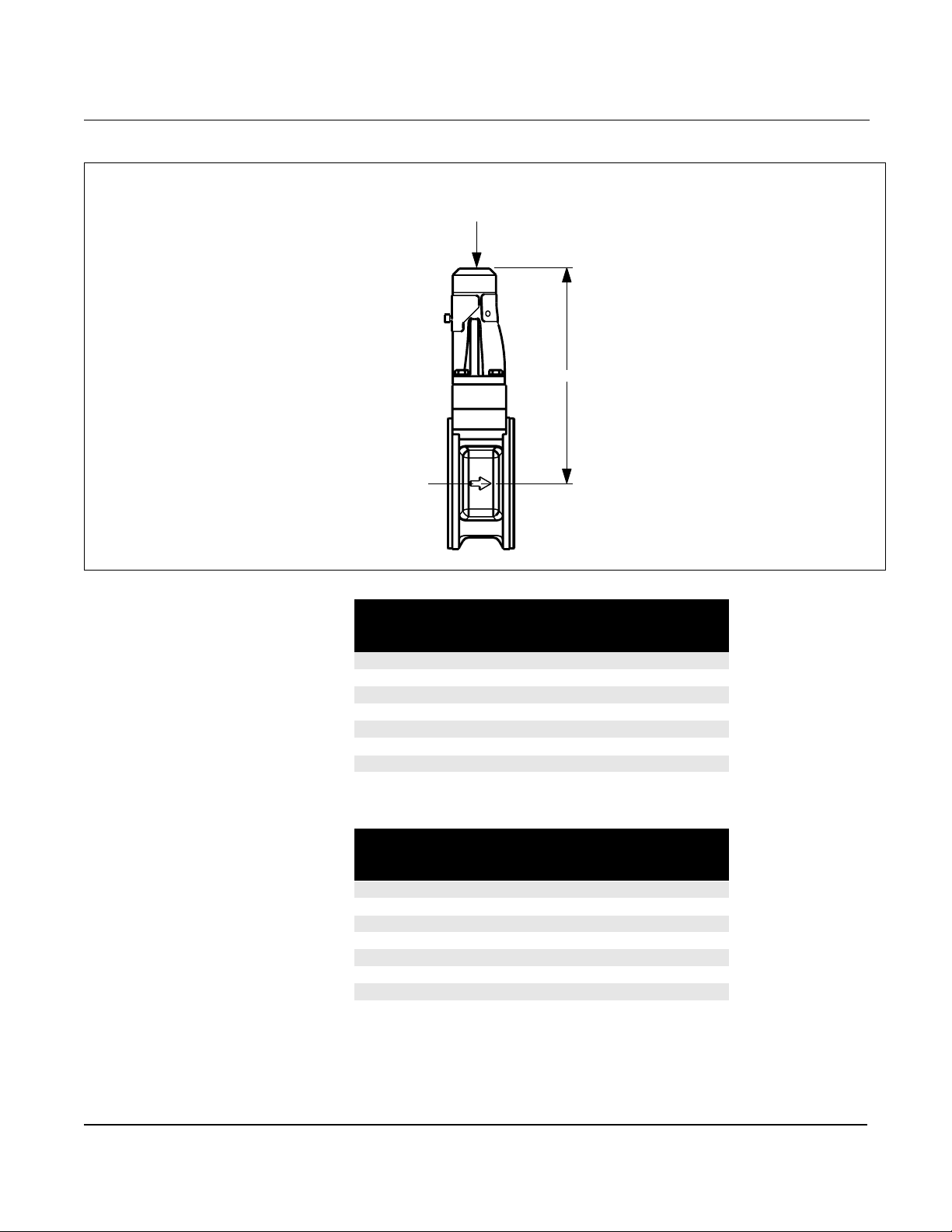
Figure 2-17. Dimensional Drawings for Remote Mount Wafer-Style Flowmeters
1
(
/2- through 8-in./15 through 200 mm Line Sizes)
1
/2-14 NPT (For Remote
Cable Conduit)
NOTE
Dimensions are in inches (millimeters)
Installation
E
8800-0002C04B
Table 2-15. Model 8800C - Stainless Steel Wafer
E
Nominal Size
Inch (mm)
½ (15) 6.4 (163)
1 (25) 6.5 (165)
1½ (40) 6.9 (175)
2 (50) 7.6 (193)
3 (80) 8.3 (211)
4 (100) 9.2 (234)
6 (150) 9.5 (241)
8 (200) 10.4 (264)
Wafer Style
Inch (mm )
Table 2-16. Model 8800A - Ha stelloy© Wafer
E
Nominal Size
Inch (mm)
½ (15) 6.3 (160)
1 (25) 6.5 (165)
1½ (40) 6.8 (173)
2 (50) 7.2 (183)
3 (80) 7.8 (198)
4 (100) 8.3 (211)
6 (150) 9.5 (241)
8 (200) 10.4 (264)
Wafer Style
Inch (mm )
2-25
Page 36
Rosemount Model 8800C Vortex Flowmeter
1
/2-14 NPT (F
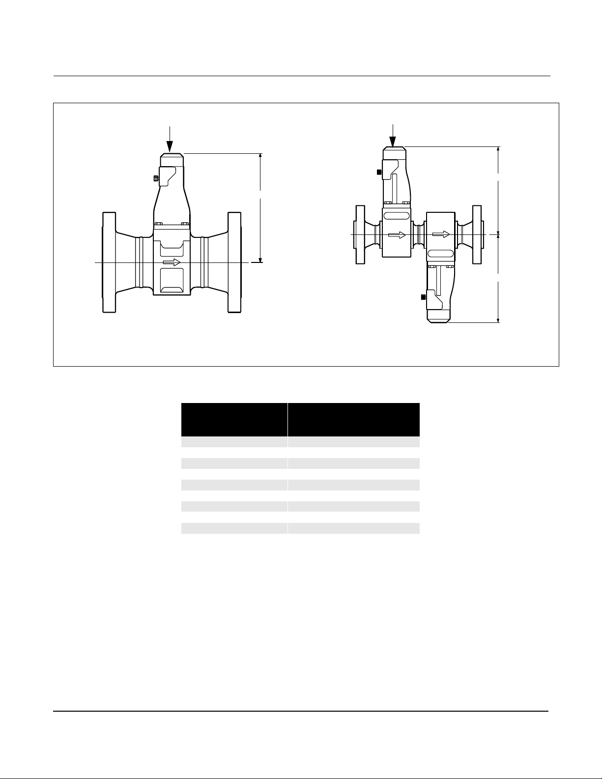
Figure 2-18. Dimensional Drawings for Flanged-and Dual-Sensor Flanged-Style Remote Mount Flowmeters
1
(
/2-through 12-inch/15 through 300 mm Line Sizes)
1
/2-14 NPT (For Remote Cable
Conduit)
Flanged Flowmeter
NOTE
Dimensions are in inches (millimeters)
E
or Remote Cable
Conduit)
Dual-Sensor Style
Flowmeter
E
E
8800-002B02C, 0006C03A
Table 2-17. Remote Mount, Flanged-and Dual Sensor Flowmeter Dimensions
E
Nominal Size
Inch (mm )
½ (15) 6.4 (16 2 )
1 (25) 6.5 (165 )
1½ (40) 6.8 ( 17 3 )
2 (50) 7.2 (183 )
3 (80) 7.8 (198 )
4 (100) 8.3 (211)
6 (150) 9.5 (241)
8 (200) 10.4 (264)
10 (250) 11.5 (292)
12 (300) 12.4 (315)
Flange Style
Inch (mm)
2-26
Page 37
Installation
Wiring Procedure The signal terminals are located in a compartment of the electronics
housing separate fr om the flowmeter electronics. Connections for a
HART-based co mmunicat or an d a curre nt t est con nect ion are above the
signal terminals. Figure 2-19 illustrates the power supply load
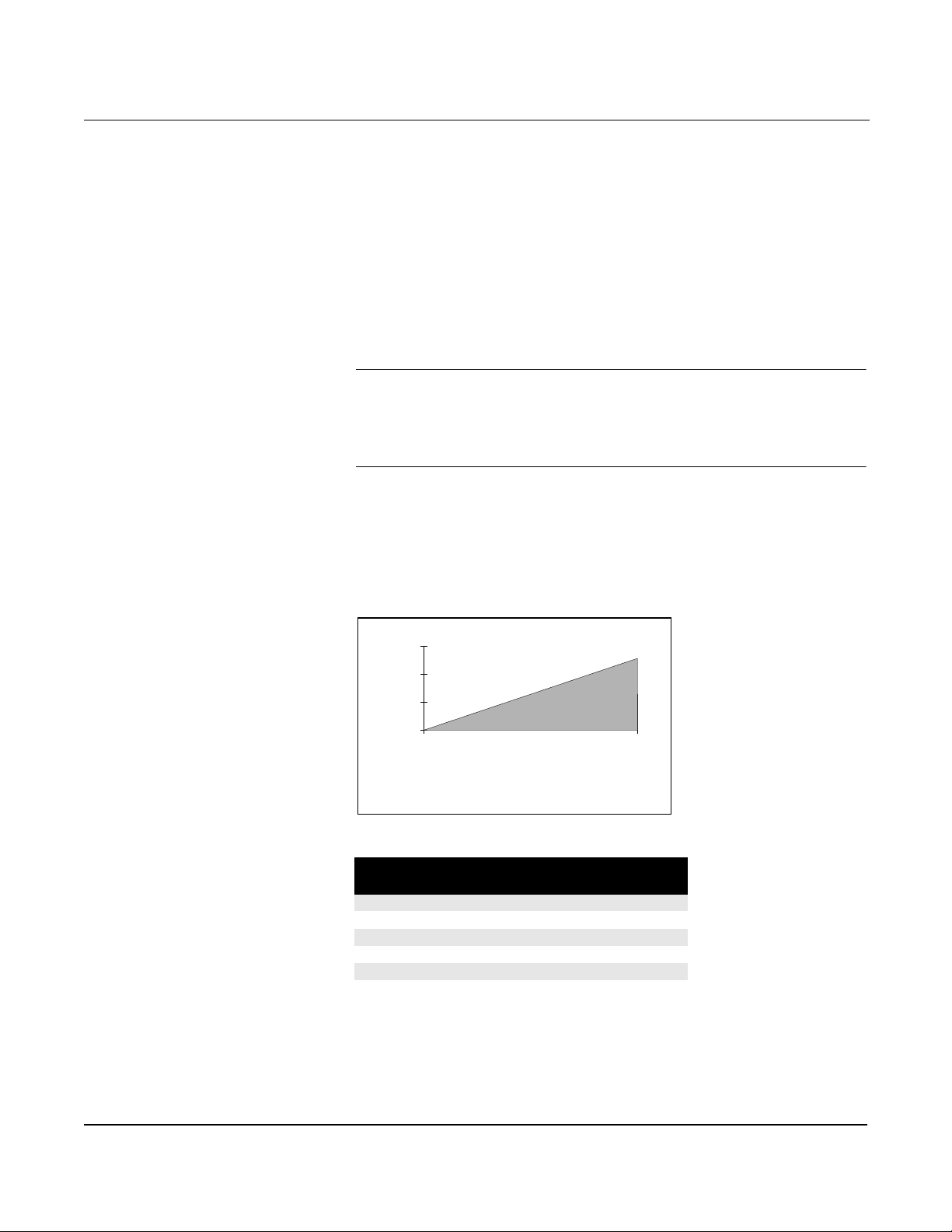
limitations for the flowmeter.
Power Supply
The dc power supply should provide power with less than two percent
ripple. The total resistance load is the sum of the resistance of the
signal wiring and the lo ad resistance of the controller, indicator, and
related pieces. Note that the resistance of intrin sic safety barriers, if
used, must be included.
NOTE
A minimum loop resistance of 250 ohm s is required to exchange
information with a HART-based communicator. With 250 ohms
of loop resistance, the flowmeter will require a minimum power supply
voltage (Vps) of 16.8 volts to output 24 mA.
If a single power supply is used to power more than one Model
8800C flowmeter, the power supply used and circuitry common
to the flowmeters should not have more than 20 ohms of
impedance at 1200 Hz.
Figure 2-19. Power Supply Load Limitations
1500
1000
500
Load (Ohms)
0
Power Supply (volts)
R
= 41.7(Vps – 10.8)
max
= power supply voltage (volts)
V
ps
= maximum loop resistance (ohms)
R
max
4210.8
T able 2-18. Wire Resistance per 1,000 Feet (305 m)
Gage Number
A.W.G.
14 2.525
16 4.016
18 6.385
20 10.15
22 16.14
24 25.67
Ohms per 1,000 ft (305 m)
at 68 °F (20 °C) Equivalent
2-27
Page 38

Rosemount Model 8800C Vortex Flowmeter
Analog Output
The flowmeter provides a 4–20 mA dc isolated current output, linear
with the flow rate.
To make connection s, remove the FIELD TERMINALS side co ver of the
electronics housing. All power to the flowmeter is supplied over the 4–
20 mA signal wiring. Connect the wires as shown in Figure 2-22 on
page 2-30.
NOTE
Twisted pairs are required to minimize noise pickup in the 4–20 mA
signal and digital communication signal. Shielded signal wire is
preferred, but not required. To ensure communication, wiring should
be 24 AWG or larger and not exceed 5,000 ft (1500 m).
Pulse Output
NOTE
Remember when using the pulse output, all power to the flowmeter
is still supplied over the 4–20 mA signal wiring.
The flowmeter provides an isolated transistor switch-closure frequency
output signal proportional to flow, as shown in Figure 2-20. The
frequency limit s are as follows:
• Maximum Frequency = 10000 Hz
• Minimum Frequency = 0.0000035 Hz (1 pulse/79 hours)
• Duty Cycle = 50%
• For Frequenc ies 0.1 Hz the pulse width will equal 5 seconds
• Supply Voltage (Vs): 5 to 30 V dc
• Load Resistance: 100 W to 100 kW
V
/0.02 amps = Ohms (typical)
s
V
/0.12 amps = Ohms (max)
s
• Switch Closure: Transistor, open collector
Open contact < 50
Close contact < 20
m
A leakage
W
The output may drive an externally powered electromechanical or
electronic totalizer, or may serve as a direct input to a control element.
To connect the wi r es, re m o ve the FIE LD TERMINALS sid e co ver
of the electronics housing. Connect the wires as show n in Figure 2-23
and Figure 2-24 on page 2-30.
2-28
Page 39
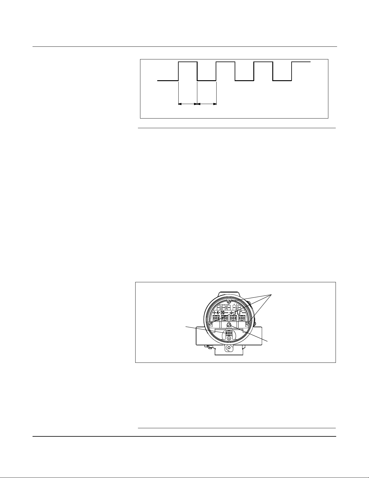
Figure 2-20. Example: The pulse output will maintain a 50 percent duty cycle for all frequencies
Installation
Figure 2-21. The Transient Terminal Block
50% Duty Cycle
8800-0546a
NOTE
When using pulse output, be sure to follow these precautions:
•Shielded twisted pair is required when the puls e output and 4–20 mA
output are run in the same conduit or cable trays. Shielded wire will
also reduce false triggering caused by noise pickup. Wiring should be 24
AWG or larger and not exceed 5,000 ft. (1500 m).
•Do not connect the powered signa l w iring to the test terminals. Power
could damage the test diode in the test connection.
•Do not run signal wiring in conduit or open trays with power wiring,
or near heavy electrical equipment. If needed, ground signal wiring at
any one point on the sign al loop, such as the negative terminal of the
power supply. The electronics housing is grounded to the spool.
•If the flowmeter is protected by the optional transient protector, you
must provide a high-current ground connection from the electronics
housing to earth ground. Also, tighten the ground screw in the bottom
center of the terminal block to provide a good ground connection.
Captive Screws
Housing Ground
Transient Terminal
Block Ground Screw
•Plug and seal all unused conduit connections on the electronics
housing to av oid moistu re accumu l a tion in the te rminal sid e
of the housing.
•If the connections are not sealed, mount the flowmeter with the
conduit entry positioned downward for drainage . Install wiring with a
drip loop, making sure the bottom of the drip loop is lower than the
conduit connections or the electronics housing.
2-29
8800-0000A03D
Page 40
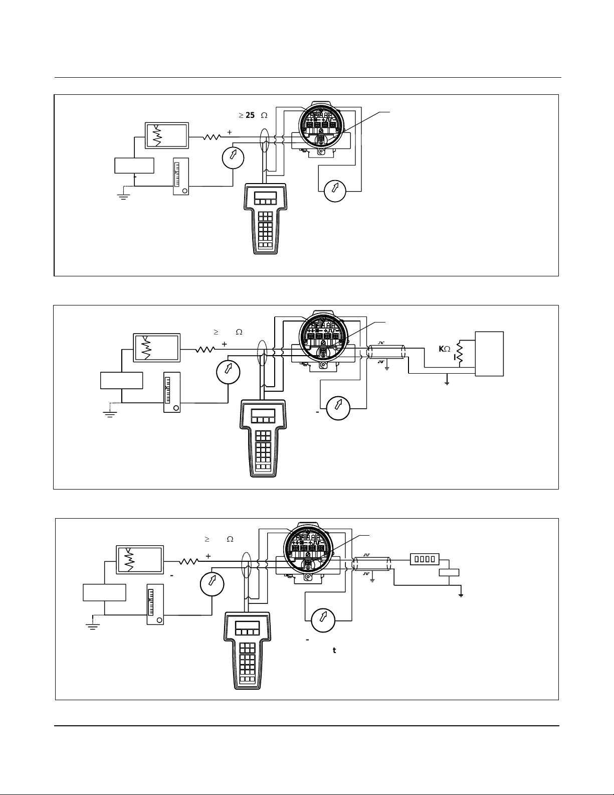
Rosemount Model 8800C Vortex Flowmeter
Figure 2-22. 4-20mA Wiring
250
R
+
–
+
W
L
+
Power
–
+
–
–
–
Test
Ammeter
Communicator
Figure 2-23. 4–20 mA and Pulse Wiring with Electronic Totalizer/ Counter
+
Power
Supply
–
RL 250
–
+
W
+
+
–
Test
Ammeter
Communicator
Housing Ground
+
A HART-based communicator may
be connected at any termination
point in the signal loop. Signal loop
must have 250 ohms minimum load
for communications.
Housing Ground
+
1K
W
(Max) Out
(1)
Typical
–
+
A HART-based communicator may be
connected at any termination point in the
signal loop. Signal loop must have 250
ohms minimum load for communications.
(1)Resistor m ay be internal or external
to Electronic Totalizer/Counter.
dc Volts Resistor < 0.12 A.
8800-0000A03C
30 V dc
Counte
r Input
8800-0000A03B
Figure 2-24. 4-20mA and Pulse Wiring with Electromechanical Counter
+
Power
Supply
–
RL 250
+
–
–
+
W
+
–
–
Test
Ammeter
Communicator
2-30
Housing Ground
+
Power
Supply
–
+
A HART-based communicator may
be connected at any termination
point in the signal loop. Signal loop
must have 250 ohms minimum load
for communication s.
(30 V max)
+
8800-0000A03A
Page 41
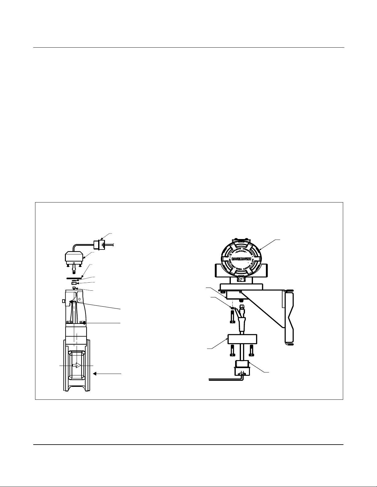
Installation
Remote Electronics If you order one of the remote electronics option s (options R10, R20,
R30, or RXX), the flowmeter assembly will be shipped in two parts:
1. The meter body with an adapter installed in the support tube and
an interconnecting coa xi a l ca b le attach e d to it .
2. The electronics housing installed on a mounting bracket.
Mounting
Mount the meter body in the proc ess flow line as describ ed earlier in
this sec ti on. Mou n t th e bracket a n d e lectroni cs housi n g in the desir e d
location. The housing can be repositioned on the brac ket to facilitate
field wiring and conduit routing.
Cable Connections
Refer to Figure 2-25 and the following instructions to connect the loo se
end of the coaxial cabl e to the electronics housing. (See Remote
Electronics Procedure on page 4-22 if connecting/disconnecting the
meter adapter to the meter body.)
Figure 2-25. Remote Electronics Installation
Optional ½–14 NPT Conduit
Adapter or Cable Gland
(Supplied by Customer)
Coaxial Cabl e
Meter Adapter
Union
Washer
Nut
Sensor Connection
Access Cover
Support Tube
Meter Body
Housing
Base
Ground
Connection
Housing
Adapter
Coaxial Cable
Electronics Housing
Mounting
Bracket for
Wall or
2-Inch Pipe
Optional ½–14 NPT
Conduit Adapter or
Cable Gland
(Supplied by
Customer)
8800-0470A02A, 0470A01B
2-31
Page 42

Rosemount Model 8800C Vortex Flowmeter
1. If you plan to run the coaxial cable in conduit, carefully cut the
conduit to the desir ed length to provide for proper assembly
at the housing. A junction box may be placed in the conduit run to
provide a space for extra coaxial cable length.
2. Slide the conduit adapter or cable gland over the loose end of the
coaxial cable and fas ten it to the adapter on the meter body
support tube.
3. If using conduit, route the coaxial cable through the conduit.
4. Place a conduit adapter or cable gland over the end of the
coaxial cable.
5. Remove the housing adapter from the electronics housing.
6. Slide the housing adapt er over the coaxial cable.
7. Remove one of the four housing base screws.
8. Attach the coaxial cable ground wire to the housing via the
housing base ground screw.
9. Attach and secur ely ti ghte n the coaxial cable nut to t he co nnectio n
on the electronics housing.
10. Align the housing adapter with the housing and attach
with three screws.
11. Tighten the conduit adapter or cable gland to the
housing adapter.
CAUTION
To prevent moisture from entering the coaxial cable connections, install
the interconnecting coaxial cable in a single dedicated conduit run or
use sealed cable glands at both ends of the cable.
Calibration Model 8800C Flowmeters are wet-cali brated at the factory and need no
further cali brat io n durin g ins tallat io n. The c ali brat ion fac tor (K-f act or)
is stamped on each meter body and is entered into the electronics.
Verification can be accomplished with a HART Communicator or AMS.
SOFTWARE CONFIGURATION
To complete the installation of the Model 8800C Vortex Flowmeter,
configure the software to meet the req uirements of your applicat ion. If
the flowmeter was pre-configured at the factory, it may be ready to
install. If not, refer to Section 3: Operation.
2-32
Page 43
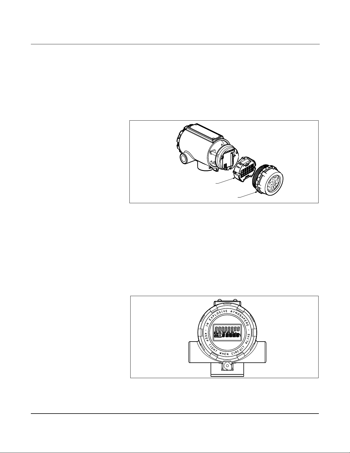
Installation
OPTIONS
LCD INDICATOR The LCD indicator (option M5) provides local indication of the output
and abbreviated diagnostic messages governing operation of the
flowmeter. The indicator is located on the circuit side of the flowmeter
electr on ics, leaving di rect acce s s to the sign a l termina l s. A n ex te n ded
cover is required to ac commod a te the indic a to r. Figure 2-2 6 sh ows the
flowmeter fitted with the LCD indicator and exte nded cover.
Figure 2-26. Model 8800C with Optional Indicator
Meter Assembly
Figure 2-27. Optional Liquid Crystal Display
Meter Cover
The indicator features an eight-character (and five alphanumeric)
liquid crystal display that gives a direct reading of the digita l signal
from the microprocessor. During normal operat ion, the display can be
configured to alterna te between four readings:
1. Primary flow variabl e in engineering units
2. Percent of range
3. Totalized flow
4. 4–20 mA electrical curr ent output
Figure 2-27 show s the indicator display w ith all segments lit.
8800-0000B01A
A HART-based communicator can be used to change the engineering
units displa yed on the indicator. (See Section 3: Operation for more
information).
2-33
8800-0463B06A
Page 44

Rosemount Model 8800C Vortex Flowmeter
Installing the Indicator For flowmeter s ordered wit h the LCD indicat or, the indicator is shipped
installed. When purc hased sepa rately fr om the Model 8800C, you must
install the indicator using a small instrument screwdriver and the
indicator kit (part number 8800-5640-0002). The indicator kit includes:
• One LCD indicator assembly
• One extended cover with o-rin g install ed
• One connector
• Two mounting screws
• Two jumpers
Referring to Figure 2-26, use the following steps to install the
LCD indicator:
1. If the flowmeter is installed in a loop, secure the loop and
disconnect the power.
2. Remove the flowmeter cover on the electronics side.
NOTE
The circuit board is electrostatically sensitive. Be sure to observe
handling precauti ons for static-sensitive components.
3. Insert the mounting screws into the LCD indicator.
4. Remove the two jumpers o n the ci rcuit board that co incide with the
Alarm and the Security settings.
5. Insert the connect or into the Alarm / Security junction.
6. Gently slide the LCD ind icator onto the connector and tighten
the screws into place.
7. Insert jumpers into ALARM and SECURITY positions on the face
of the LCD indicato r.
8. Attach the extended cover and tighten at least one-third turn past
o-ring contact.
NOTE
The indicator may be installed in 90-degree increments for easy
viewing. One of the four connectors on the back of the indicator
assembly must be posit ioned to fit into the ten-pin connector on the
electronic board stack.
Note the following LCD temp erature limits:
Operating: –4 to 185 °F(–20 to 85 °C)
Storage: –50 to 185 °F (–46 to 85 °C)
2-34
Page 45

Installation
Diagnostic Messages In addition to the output, the LCD indicator displays diagnostic
messages for troubleshooting the flowmeter. These messages
are as follows:
SELFTEST
The flowmeter is in the process of performing an electronics self test.
FAULT_ROM
The flowmeter electr onics has undergone a EPROM checksum fault.
Contact your Field Service Center.
FAULT_EEROM
The flowmeter electronics has undergone a EEPROM checksum fault.
Contact your Field Service Center.
FAULT_RAM
The flowmeter electroni cs has undergone a RAM test fault.
Contact your Field Service Center.
FAULT_ASIC
The flowmeter electronics has undergone a digita l signal processing
ASIC update fault. Contact your Field Service Center.
FAULT_CONFG
The flowmeter electronics has lost criti cal configuration parameters.
This message will be followed by information detailing the missing
configuration parameters. Contact you r F ield Service Center.
FAULT_COPRO
The flowmeter electronics has detected a fault in the math coprocessor.
Contact your Field Service Center.
FAULT_SFTWR
The flowmeter electronics has detected a non-re coverable fault in the
software operation. Contact your Field Service Center.
FAULT_BDREV
The flowmeter electronics has detected incompatible electronics
hardware. Contact your Field Service Center.
FAULT_LOOPV
The flowmeter electr onics has dete cted ins uffic ient voltage to power the
sensor board. Most likely the cause is low voltage at transmitter
4–20 mA terminals. Contact your Field Service Center.
FAULT_SDCOM
The flowmeter electronics has detected an unexpected sigma-delta
ASIC communications fault. Contact your Field Service Center.
2-35
Page 46

Rosemount Model 8800C Vortex Flowmeter
FAULT_SDPLS
The flowmeter electronics has detected a loss of flow data from the
sigma-delta ASIC. Contact your Field Service Center.
FAULT_TASK(#)
The flowmeter electronics has detected a fatal error. Record (#) and
contact your Field Service Center.
TRANSIENT PROTECTION The optional transient terminal block prevents damage to the
flowme te r from tran sients induced by lightning, w e lding, heavy
electrical equipment, or switch gears. The transient protection
electronics are located in the terminal block.
The transient terminal block meets the following specifications:
ASME B16.5 (ANSI)/IEEE C62.41 - 1980 (IEEE 587) Categories A, B.
m
3 kA crest (8 20
s).
Installing the
Transient Protector
6 kV crest (1.2 50
6 kV/0.5 kA (0.5
NOTE
The ground screw inside the terminal housing must be tightened for
the proper operation of the transient protection. Also, a high-current
ground connection to earth is required.
For flowmeters order e d with the transient protector option (T1), the
protector is shi pped installed. When purchased separately from the
Model 8800C, you must install the protector on a Model 8800C
flowmeter using a small instrument screwdriver, a pliers, and
the transient protection kit (part number 8800- 5106-1002 or
8800-5106-1004).
The tran sient pro t ec tion kit in cl udes the fo llowing:
• One transient protection terminal block assembly
• Three captive screws
• One ground screw
m
s).
m
s, 100 kHz, ring wave).
2-36
Page 47
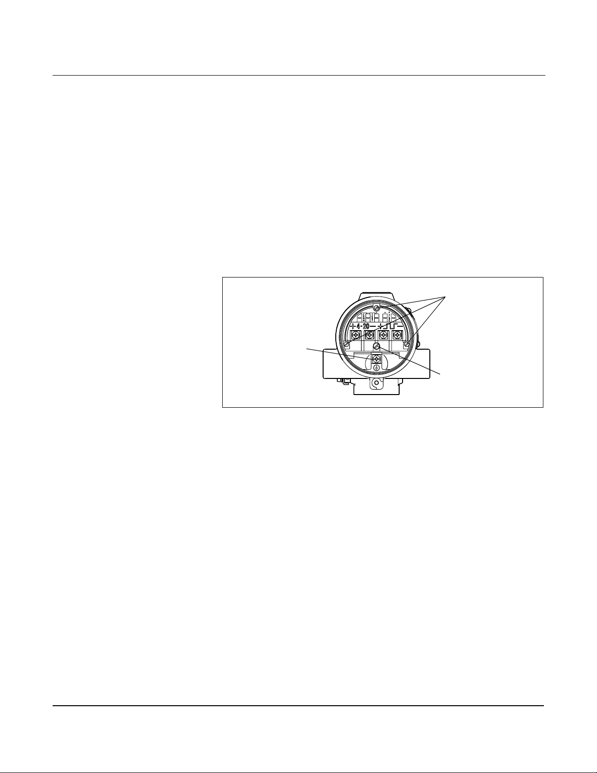
Figure 2-28. The Transient Terminal Block
Installation
Use the following steps to install the transient protector:
1. If the flowmeter is installed in a loop, secure the loop and
disconnect power.
2. Rem o ve the fiel d termin a l si de flowmeter cov er.
3. Remove the captive screws.
4. Use pliers to pull the terminal block out of the housing.
5. Inspect the connect or pins for straightness.
6. Place the new terminal block in position and carefully press it into
place. The terminal block may have to be moved back and forth to
get the connector pi ns started into the socke ts.
7. Tigh ten the ca p ti ve screw s.
8. Install and tighten the ground screw.
Captive Screws
Housing Ground
9. Replace the cover.
Transient Termina l
Block Ground screw
8800-0000A03D
2-37
Page 48

Rosemount Model 8800C Vortex Flowmeter
2-38
Page 49
Section
3 Operation
Review . . . . . . . . . . . . . . . . . . . . . . . . . . . . . . . . . . . . . . . . . page 3 -1
Process Variables . . . . . . . . . . . . . . . . . . . . . . . . . . . . . . . . page 3-1
Diagnostics/Service . . . . . . . . . . . . . . . . . . . . . . . . . . . . . . page 3-3
Basic Set u p . . . . . . . . . . . . . . . . . . . . . . . . . . . . . . . . . . . . . page 3 -5
Advanced Functionality . . . . . . . . . . . . . . . . . . . . . . . . . . . page 3-12
Detaile d Set- U p . . . . . . . . . . . . . . . . . . . . . . . . . . . . . . . . . . page 3-12
The software configuration settings for the Model 8800C can be accessed
through a HART-based communicator or through a control system. The
software functions for the HART Communicator are described in detail
in this section of the manual. It provides an overview and summary of
communicator functions. For more complete instructions, see the
communicator manual.
Before operating the Model 8800C in an a ctual installation, you should
review all of the factory set configuration data to ensure that they
reflect the current application.
REVIEW Review the flowmeter configuration parameters set at the factory to
HART Comm. 1, 5
ensure accuracy and compatibility with your particular applicati on
of the flowmeter. Once you have activated the Review function,
scroll through the data list to check each variable in the configuration
data list.
The last step of start-up and com missioning is to chec k the flowmeter
output to ensur e th at the f lowmete r is ope rat ing p roperly. Model 8800 C
digital outputs i nclude : flow rate , f low rate as a per cent of range, ana log
output, vortex shedding rate, pulse rate, and totalized flow.
PROCESS VARIABLES
HART Comm. 1, 1
The process variables for the Model 8800C provide the flo w met er
output. They measure flow in several ways that refle ct your needs and
the configurati on of your flowmeter. When commissioning a flowmeter,
review each process variable, its function and output, and take
corrective action if necessary before using the flowmeter in a process
application.
Flow – The actual measure d flow rate in the line. On the bench, the PV
value should be zero. Check the units on the PV to make sure they are
configured correc tly. If the units format is not corr ect , refer t o PV Units
on page 3-14. Use the Process Variable Units function to select the
units for your application.
Percent of Range – The process variable as a percentage of range
provides a gauge as to wher e the current flow of th e meter is withi n the
configured range of the flowmeter. For example, the range may be
defined as 0 gal/min to 20 gal/mi n. If the curr ent flow is 10 gal /min, the
percent of range is 50 percent.
3-1
Page 50
Rosemount Model 8800C Vortex Flowmeter
Analog Output – The analog output variable provides the analog
value for the flow rat e. The analog output refers to the industry
standard output in the 4–20 mA range . Check the analog output
value against the actual loop reading given by a millimeter.
If it does not match, a 4–20 mA trim is required . S ee D /A T rim
(Digital-to-Analog Trim).
Totalizer – Totalizer pr ov i de s a reading of the tot a l flow of the
flowmeter since the totalizer w as last reset. The total izer value should
be zero during com missioning on t he bench, and the units should re flect
the volume units of the flow rate. If the totalizer value is not zero, it
may need to be reset.
Vi ew Other Variables– Pulse Output prov ides the a ctual pulse r eading
from the meter if your meter includes the pulse output option. This
digital value is always available, even without the pulse output option.
Shedding Frequency measur es the fre quency of vortex pu lses ar ound
the shedder bar.
Totalizer Totalizer tallies the total amount of liquid or gas that has passed
HART Comm. 1, 1, 4
throug h th e fl o w meter sin ce the tot alizer was la st reset.
It enables you to change the settings of the totalizer.
Total
HART Comm. 1, 1, 4, 1
Total — Provides the output reading of the totalizer. Its value is the
amount of liquid or gas that has passed through the flowmeter since
the totalizer was las t reset
Start
HART Comm. 1, 1, 4, 2
Start — Starts the totaliz e r countin g fro m it s curren t v al u e.
Stop
HART Comm. 1, 1, 4, 3
Stop — Interrupts the totalizer count until it is restarted again. This
feature is often used during pipe cleaning or other maintenance
operations.
Reset
HART Comm. 1, 1, 4, 4
Reset — Stops the totalizer and returns the totalizer value to zero.
NOTE
The totalizer value is saved in the EEPROM memory of the electr onics
every three minutes if the temperature is less than 131 °F (55 °C) or
every six minutes if the temperature is greater than 131 °F (55 °C).
Should power to the tran smitt er be i nter rupted, the to talize r val ue will
start at the last saved value when power is re-applied.
3-2
Page 51
Operation
DIAGNOSTICS/SERVICE Use the following functions to verify that the flowmeter is functioning
HART Comm. 1, 2
properly, or when you suspect co mponent f ai lure or a probl em wit h loo p
performance, or when instructed to do so as part of a troubleshooting
procedure. Initiate each test with the HART Communicator or other
HART-based communications device.
Test/Status Under Test/Status choose from View Status or Self Test.
HART Comm. 1, 2, 1
View Status
HART Comm. 1, 2, 1, 1
View Status allows you to view any error messages that may
have occurred.
Self Test
HART Comm. 1, 2, 1, 2
Although the Model 8800C perfor ms continuous self-diagnos tics, you
can initiate an immediate diagnostic to check for possible electronics
failure.
Self Test checks proper communications with the transmitter and
provides diagnostic capabilities for transmitter problems. Follow
on-screen instructions if problems are detected, or check the
appropriate appendix for error messages relating to your
communicator.
Loop Test Loop T est verif ies the output of the flowmeter, the integrity o f the loop ,
HART Comm. 1, 2, 2
and the operation of any recorders or similar devices. Conduct the loop
test after the flowmeter is installed in the field.
If the meter is located in a loop with a control system, the loop will have
to be set to manual control before the loop test is performed.
Verify that the ammeter in the test loop reads 4 mA. If the output is
4 mA, end the loop test. If the output is not 4 mA, the flowmeter may
require a digital trim. If the digital trim does not set the 4 mA output,
the electroni cs ma y be malfunctioning.
Pulse Output Test Pulse Output Test is a fixed frequency mode test that checks the
HART Comm. 1, 2, 3
integrity of the pulse loop. It tests that all connections are good and
that pulse output is runn ing on the loop.
Flow Simulation Flow Simulation enables you to check the electronics functionality.
HART Comm. 1, 2, 4
This can be verified with eit her the Flow Simulation Internal or Flow
Simulation External method.
Flow
HART Comm. 1, 2, 4, 1
Shows the flow value in current engineering units for the flow
simulation.
3-3
Page 52
Rosemount Model 8800C Vortex Flowmeter
Shedding Frequency
HART Comm. 1, 2, 4, 2
Shows the shedding frequency for the flow simulation.
Configure Flow Simul ation
HART Comm. 1, 2, 4, 3
Allows you to configure your flow simulation (internal or external).
Simulate Flow Internal
HART Comm. 1, 2, 4, 3, 1
The simulate flow internal function will automatically disconnect the
sensor and enable you to select the configuration of the internal
simulate (fixed or varying).
Fixed Flow
HART Comm. 1, 2, 4, 3, 1, 1
The fixed flow simulation signal can be entered in either a percent of
range or flow rate in current engineering units.
Varying Flow
HART Comm. 1, 2, 4, 3, 1, 2
The minimum and maximum flowrate can be entered in either percent
of range or as a flow rate in current engineering units. The ramp time
can be entered in seconds fr om a minimum of 0.533 seconds to a
maximum of 34951 seconds.
Simulate Flow External
HART Comm. 1, 2, 4, 3, 2
Simulate flow extern al allows you to disconnect the senso r
electronically so an external frequency source can be used.
Enable N o rmal Flow
HART Comm. 1, 2, 4, 4
Enable normal flow allows you to exit the flow simulation mode
(internal or external) and return to normal operation mode.
Mode
HART Comm. 1, 2, 4, 5
Mode allows you to view which flow simulation mode you are in:
• Int er n a l (flow simu lation – internal)
• Snsr Offln (flow simulation – exte rnal)
• Norm Flow (normal flow operation)
3-4
Page 53
Operation
D/A Trim D/A Trim (Digital-to-Analog Trim) enables you to check and trim
HART Comm. 1, 2, 5
the analog output i n a single function. If the analog output is trimmed,
it will be scaled proportionally through the range of the output.
To trim the digital-to-analog output, initiate the D/A Trim function and
connect an ammeter to the loop to m easure the actual analog output of
the meter. Follow the on-screen functions to complete the task.
Scaled D/A Trim Scaled D/A Trim enables you t o c alibrat e t he flow meter analog out put
HART Comm. 1, 2, 6
using a different scal e than the standard 4-20 mA output scale.
Non-scaled D/A Trimming (described above), is typically performed
using an ammeter where calibration values are entered in units of
milliamperes. Both non-scaled D/A trim ming and scaled D/A trimming
allow you to trim the 4-20mA output to approximately ±5% of the
nominal 4mA end point and ±3% of the nominal 20mA end point.
Scaled D/A Trimming allows you to trim the flowmeter using a scale
that may be more convenient base d upon your method of measurem ent.
For example, it ma y be more convenient for you to make current
measurements by direct voltage readings across the loop resistor. If
your loop resistor is 500 Ohms, and you want to calibrate the meter
using voltage measurements made across this resisto r, you could
rescale (select CHANGE on the 275) your trim points from 4-20mA to
4-20mA x 500 ohm or 2-10 VDC. Once your scaled trim points have
been entered as 2 and 10, you can now calibrate your flowmeter by
entering voltage measurements directly from the voltmeter.
Shed Freq at URV Shed Freq at URV function gives the shedding frequency
HART Comm. 1, 2, 7
corresponding to your URV.
BASIC SETUP The Model 8800C must be configured for certain basic variables in order
HART Comm. 1, 3
to be operational. In most cases, all of these variables are pre-configured
at the factory. Configuration may be required if your Model 8800C is not
configured or if the configuration variables need revision.
Tag Tag is the qui ck es t way to identify a nd disting u is h be tween
HART Comm. 1, 3, 1
flowmeters . Flowmete rs c an be tagged acco rdi ng to the requi rement s of
your application. The tag may be up to eight characters long.
Service Type The flowmeter can be used for liquid or gas/steam applications, but it
HART Comm. 1, 3, 2
must be co n f ig ured specifically fo r the application . If the flowme ter is
not configured fo r the proper service type , readings will be inaccurate.
Select the appropriate Service Type for your application:
• Liquid
• Gas/Steam
3-5
Page 54
Rosemount Model 8800C Vortex Flowmeter
PV Units The Model 8800C flowmeter displays Volumetric, Mass, STD/Normal,
HART Comm. 1, 3, 3
Velocity, or Speci a l un i ts as dete rmined by yo u r a pplicat ion. Use the
Process Variable Units (PV) function to select the units for your
application and needs.
NOTE
After changing flow units, be sure to send data to the transmitter so that
the associated variables (4–20 mA points, etc.) will be recalculated by the
microprocessor. The Model 8800C recalculates all variables that depend
on units. You may then change any of the remaining parameters.
The following flow unit options are available:
Volumetric Units
HART Comm.
1, 3, 3, 1
Volumetric Units (1 bbl = 42 gal)
gal/s impgal/s
gal/min impgal/min
gal/h impgal/h
gal/d impgal/d
ACFM L/s
ACFH L/min
ACFD L/h
bbl/min L/d
bbl/h ACMM
bbl/d ACMH
ACMD
MACMD
Mass Units
HART Comm. 1, 3, 3, 2, 1
Mass Flow Units
If you select a Mass Units option, you must enter process density in
your configuration. (1 ston = 2000 lb; 1 ton = 1000 kg)
lb/s ston/h
lb/min ston/d
lb/h met ton/h
lb/d met ton/d
kg/s
kg/min
kg/h
kg/d
3-6
Page 55
Operation
Process Density
HART Comm. 1, 3, 3, 2, 2
Process Density and Density Units are required only if you have
designated mass units for your flow rate units. You will first be
prompted for density units. It is required for the conversion from
volumetric units to mass units. If you select volumetric units or special
units, process den s it y is not req u ir ed .
For example, if you have set flow units to kg/sec rather than gal/sec, a
density is required to convert the measured volumetric flow into the
desired mass flow.
NOTE
If mass units are configured as special units , process density must be
figured into the special units conversion number. Process density as
a separate value will be de-activated.
If mass units are chosen, you must enter the density of your process
fluid into t he s oft w are . Be ca ref ul to ente r t he correc t d ensi ty. The mass
flow rate is calculated using this use r-entered density, and any error in
this number will cause error in the mass flow measurement. If fluid
density is changing over time, it is recommended that volumetric flow
units be used.
STD/Normal Flow Units
HART Comm. 1, 3, 3, 3, 1
Standard/Normal Flow Units
SCFM
SCFH
NCMM
NCMH
NCMD
The model 8800C allows you to measure Standard or Normal Flow
Units. Configure the software in one of two ways:
1. Enter Density Ratio to convert from actual flow rate to standard
flow rate.
2. Enter the process and base con ditions. (The Model 8800C
electronics will then calculate the density ratio for you).
NOTE
Be careful to calculate a nd enter t he corre ct conve rsion facto r. Standard
flow is calculated with the conversi on fact or you enter. Any error in the
factor entered will result in an error in the standard flow
measurement. If pressure and temperature changes over time, use
actual volumetr ic flo w unit s . The M odel 8800C do es not compen sate for
changing temperatur e and pressure.
3-7
Page 56

Rosemount Model 8800C Vortex Flowmeter
Density Ratio
HART Comm. 1, 3, 3, 3, 2
Density Ratio is used to convert act ual volumetric flow to standard
volumetric flo w ra tes based on the following equat ions:
Conversion factor
Conversion factor
dens ity at actual (flowing) conditions
------------------------------------------------------------------------------------------------------------=
density at s dard (base)tan conditions
TbP
Z
f
-------------------------------=
TfP
b
Z
b
f
Calculate Density Ratio
HART Comm. 1, 3, 3, 3, 3
Calculate Density Ratio will calculate the density ratio (shown
above) based on user entered process and base conditions.
Operating Conditions
HART Comm. 1, 3, 3, 3, 3, 1
Tf = absolute temperatur e at actual (flowing) conditions in degrees
Rankine or Kelvin. (Th e transmitter will conve rt from degrees
Fahrenheit or degrees Cel sius to degrees Rankine or Kelvin
respectively .)
P
= absolute pressure at actual (flowing) conditions psia or KPa
f
absolute. (The transmitter will convert from psi, bar, kg/sqcm, kpa, or
mpa to psi or kpa for calculation. Note that pressure val u es mu st be
absolute.)
Z
= compressibility at actual (flowing) conditions (dimensionless)
f
3-8
Base Conditions
HART Comm. 1, 3, 3, 3, 3, 2
Tb = abso lute t emp eratu re at sta ndard (b ase ) co nditi ons degrees Ranki ne
or Kelvin. (The transmitter will convert from degrees Fahrenheit or
degrees Cels ius to degr ees Ranki ne or Kelv in res pec tivel y.)
= absolute pressure at standard (base) conditions psia or KPa
P
b
absolute. (The transmitter will co nvert from psi, bar , kg/ sqcm, kpa, or mpa
to psi or kpa for calculation. Note that pressure values must be absolute.)
= compre s si b ility at stan d ard (base) conditions (dime n s io nless)
Z
b
Example
Configure the Model 8800C to display flow in standard cubic feet per
minute (SCFM). (Fluid is hydroge n flowi n g at conditions of 170 °F and
100 psia.) Assume base conditions of 59 °F and 14.696 psia.)
Conversion fact or
518.57 °R 100 psia1.0006
---------------------------------------------------------------------------------- - 5.587==
629.67 °R 14.7 psia1.0036
Page 57
Operation
Velocity Units
HART Comm. 1, 3, 3, 4
ft/sec m/sec
Special Units
HART Comm. 1, 3, 3, 5
Special Units allows you to create flow rate units that are not among
the standard options. They can be mass or volumetric units.
Configuration of a special unit involves entry of these values: base
volume unit, base time unit, user defi ned unit and conversion number.
Suppose you want the Model 8800C to display flow in barrels per
minute instead of gallons per minute, and one barrel is equal to
31.0 gallons.
• Base volume unit: gal
• Base time unit: min
• User defined unit: br
• Conversion number: 31.0
See the specific variables listed below for more information on setting
special u n its.
NOTE
The HART -based communicator will display the converted reading. The
actual unit specification does not appear.
Base Volume Unit
HART Comm. 1, 3, 3, 5, 1
Base Volume Unit is the unit from which the conversio n is made. You
must select one of the HART Communicat or defined unit options:
• Gallons (gal)
• Liters (L)
• Imperial gallons (Impgal)
• Cubic meters (Cum)
• Barrels (bbl) where 1 standard bbl=42 gal
• Cubic Feet (cuft)
Base Time Unit
HART Comm. 1, 3, 3, 5, 2
Base Time Unit provides the time unit from which to calculate the
special units . For example , if your specia l units is a volume per minute ,
select minutes. Choose from the following units:
• Seconds (s)
• Minutes (min)
• Hours (h)
• Days (d)
3-9
Page 58
Rosemount Model 8800C Vortex Flowmeter
User Defined Unit
HART Comm. 1, 3, 3, 5, 3
User Defined Unit is a format variable that provides a record of the
flow units to which you are converting. The LCD on the Model 8800C
will display the actual units you define. The HART communicator will
simply display “SPCL.” There are four ch aracters available to store the
new units designation.
Conver sion Number
HART Comm. 1, 3, 3, 5, 4
Conversion Number is used to relate base units to special units. For
a straight conversion of volume units from one to another, the
conversion number is the number of base units in the new unit.
Fo r exa mple , if you ar e conver tin g fr om gall ons to barrel s and there are
31 gallons in a barrel, the conversion factor is 31. The conversion
equation is as follows (where barrels is the new volume unit):
1 barrel=31 gallons
NOTE
If reviewing parameters, the number is show n as the conversion factor
from base units to speci al units (i.e., 1/31).
Range Values Range Values enables you to maximize resolution of analog output.
HART Comm. 1, 3, 4
The meter is most accura te w h en operated within the expect ed flow
ranges for your application. Setting the range to the limits of expected
readings will maximize flowmeter performance.
The range of expected readin gs is defined by the Lower Range Value
(LRV) and Upper Range Value (URV). Set the LRV and URV wi thin t he
limits of flowmeter operation as defined by the li ne size and process
material for your application. Values set outside that range will not be
accepted.
Select each variable and enter the appropriate value. The new range is
defined by these values.
Process T emperature Process Temperat ure is needed for the electronics to compensate for
HART Comm. 1, 3, 5
thermal expansion of the flowmeter as the process tem p erature differs
from the reference temperature. Process temperature is the
temperature of the liquid or gas in the line during flowmeter operation.
NOTE
The temperature may also be changed under Calculate Density Ratio .
3-10
Page 59
Operation
Mating Pipe ID
(Inside Diameter)
The Pipe ID (Inside Diam eter ) of th e pipe adj acent to th e flo w mete r
can cause entrance effect s that may alte r flowmeter re adings . You must
specify the exact inside diameter of the pipe to correct for these effects.
HART Comm. 1, 3, 6
Enter the appropriate value for this variable.
Pipe ID values fo r s chedule 10, 40, and 80 p iping ar e gi ven in Table 3-1.
If the piping in your application is not one of these, you may need to
contact the manufacturer for exact Pipe ID.
f
Table 3-1. Pipe IDs for Schedule 10, 40, and 80 Piping
Pipe Size
Inches (mm)
½ (15) 0.674 (17.12) 0.6 22 (15.80) 0.546 (13.87)
1 (25) 1.097 (27.86) 1.049 (26.64) 0 .957 (24.31)
1½ (40) 1.682 (42.7 2) 1.610 (40.89) 1.500 (38.10)
2 (50) 2.157 (54.79) 2.067 (52.50) 1 .939 (49.25)
3 (80) 3.260 (82.80) 3.068 (77.93) 2 .900 (73.66)
4 (100) 4.260 (108.2) 4.026 (102.3) 3.826 (97.18)
6 (150) 6.357 (161.5) 6.065 (154.1) 5.716 (145.2)
8 (200) 8.329 (211.6) 7.981 (202.7) 7.625 (193.7)
10 (250) 10.420 (264.67) 10.020 (254.51) 9.562 (242.87)
12 (300) 12.390 (314.71) 12.000 (304.80) 11.374 (288.90)
Schedule 10
Inches (mm)
Schedule 40
Inches (mm)
Schedule 80
Inches (mm)
Damping Damping changes the response time of the flowme ter to smooth
HART Comm. 1, 3, 7
variations in outp ut readings caused by rapid changes in input. Damping is applied to the Analog Output, Process Variable, and
Percent Range. This will not affect the Pulse Output or Total.
NOTE
If the vortex shedding frequency is slower than the damped value
selected, no dam ping is applied.
The default damping value is 2.0 seconds. This can be reset to any
value between 0.2 and 255 seconds.
Determine the appropriate damping setting based on the necessary
response time, signal stabilit y, and other require ments of the loop
dynamics in your system.
3-11
Page 60
Rosemount Model 8800C Vortex Flowmeter
ADVANCED FUNCTIONALITY
The Model 800C enables you to configure the flowmeter for a wider
range of applications and special situations. These functions are
grouped as follows under Detailed Set-Up:
DETAILED SET-UP • Characterize Meter
HART Comm. 1, 4
• PV Units
• Configure Outputs
• Signal Processing
• Device Information
Characterize Meter The Meter Body variabl es provide conf igurati on data that are uni que to
HART Comm. 1, 4, 1
your Model 8800C. The settings of these variables can effect the
compensated K-factor on which the primary variable is based. These
data are provided during factory configuration and should not be
changed unless the physi cal make-up of your Model 8800C is change d.
Mating Pipe I.D.
HART Comm. 1, 4, 1, 1
The inside diameter of the pipe adjacent to the flow meter can cause
entrance effects that may alter flowmeter readings. The exact inside
diameter of the pipe mus t be specifi ed to co rre ct for th ese effe cts. Enter
the appropriate val u e for this variable.
Mating Pipe ID values for schedule 10, 40, and 80 piping are given in
Table 3-1. If the piping in your application is not one of these, you ma y
need to contact the manufact urer for exact Pipe ID.
K-Factor
HART Comm. 1, 4, 1, 2
The HART Communicator provides information on Reference and
Compensated K-factor values.
The Referenc e K-fact or is f actory s et ac cor ding to t he act ual K- factor for
your application. It should only be changed if you replace parts of the
flowmeter. Contact your Rosemount representative for details.
The Compensated K-factor is based on the reference K-factor as
compensated for the g iven proc ess temper atur e, wet ted materi als , body
number, and pipe ID. Comp ensated K -factor is an in f or m a tional
variable that is calculated by the ele ctronics of your flowmeter.
Wetted Material
HART Comm. 1, 4, 1, 3
Wetted Material is a factory set configuratio n variable that reflects
the constructi on of your flowmeter.
• 316 SST
• Hastelloy-C
®
3-12
Page 61
Operation
Meter Body Number
HART Comm. 1, 4, 1, 4
Meter Body Number is a factory set configuration variable that
stores the body number of your par ticular flowmeter and the type
of construction. The meter body number is found to the right of the
body number on the meter body tag, which is attac hed to the support
tube of the m e te r b ody.
The format of this variable is a number followed by an alpha numeric
character. The number designates the body number. The alpha numeric
character desi gnates the meter body type . There are three options for
the alpha numeric character:
1. None – Indicates welded met er construction
2. A – Indicates welded meter construction
3. B – Indicates cast construction
Flange Type
HART Comm. 1, 4, 1, 5
Flange Type enables you to specif y t he type of f lange o n t he f lowmet er
for later refe rence. This varia ble is preset at the facto ry but can be
changed if necessary.
• Wafer
• ASME B16.5 (ANSI) 150
• ASME B16.5 (ANSI) 300
• ASME B16.5 (ANSI) 600
• ASME B16.5 (ANSI) 900
• PN 10
• PN 16
• PN 25
• PN 40
• PN 64
• PN 100
• PN 160
• JIS 10k
• JIS 20k
• JIS 40k
• Special
Installation Effect
HART Comm. 1, 4, 1, 6
Installation Effect enables you to compensate the flowmeter for
installation effects. See reference graphs located in Te chnical Data
Sheet 00816-0100-3250 for the percent of K-factor shift based on
entrance effec ts of upstream disturbances. This value is entered as a
percentage of th e ra n ge of +1.5% to -1.5%.
3-13
Page 62
Rosemount Model 8800C Vortex Flowmeter
PV Units Refer to the previous pages for more details regarding the following:
HART Comm. 1, 4, 2
Volumetric Units, Mass Units, STD/Normal Units, Velocity Units, and
Special Units.
Config ur e O ptions The Model 8800C is digitally adjusted at the factory using precision
HART Comm. 1, 4, 3
equipment to ens ure a ccur acy. You should be able to install and operate
the flowmeter without a D/A Trim.
Analog Output
HART Comm. 1, 4, 3, 1
For maximum accuracy, calibrate the analog output and, if necessary,
trim for your system loop. The D/A Trim procedure alters the
conversion of the digital signal into an analog 4–20 mA output.
Range Val ues
HART Comm. 1, 4, 3, 1, 1
Range Values enables you to maximize resolution of analog output .
The meter is most accura te w h en operated within the expect ed flow
ranges for your application. Setting the range to the limits of expected
readings will maximize flowmeter performance.
The range of expected readin gs is defined by the Lower Range Value
(LRV) and Upper Range Value (URV). Set the LRV and URV wi thin t he
limits of flowmeter operation as defined by the li ne size and process
material for your application. Values set outside that range will not be
accepted. Select each variable and enter the appropriate value. The
new range is defined by these values.
Loop Test
HART Comm. 1, 4, 3, 1, 2
Loop T est verif ies the output of the flowmeter, the integrity o f the loop ,
and the operation of any recorders or similar devices. Conduct the loop
test after the flowmeter is installed in the field. If the meter is located
in a loop with a control system, the loop will have to be set to manual
control b efore the lo op te st is perfo r m e d .
Verify that the ammeter in the test loop reads 4 mA. If the output is
4 mA, end the loop test. If the output is not 4 mA, the flowmete r ma y
require a digital trim (see D/A Trim (Digital-to-Analog Trim). If the
digital trim does not set the 4 mA output, the receiving meter may be
malfunctioning.
Alarm Jumper
HART Comm. 1, 4, 3, 1, 3
Alarm Jumper lets you verify the alarm jumper setting.
3-14
Page 63
Operation
D/A Trim (Digital-to-Analog Trim)
HART Comm. 1, 4, 3, 1, 4
Digital-to-Analog Trim enables you to check and trim the analog
output in a single fu n c tion. If the an a log outp u t is trimmed, it will be
scaled proportionally through the range of the output. To trim the
digital-to-a nalog output, initiate the D/A Trim func tion and connect an
ammeter to the loop to measure the actual analog output of the meter.
Follow the on-scre en functions to complete the ta sk.
Scaled D/A Trim
HART Comm. 1, 4, 3, 1, 5
Scaled D/A Trim enables you t o c alibrat e t he flow meter analog out put
using a different scal e than the standard 4-20 mA output scale.
Non-scaled D/A Trimming (described above), is typically performed
using an ammeter where calibration values are entered in units of
milliamperes. Both non-scaled D/A trim ming and scaled D/A trimming
allow you to trim the 4-20mA output to approximately ±5% of the
nominal 4mA end point and ±3% of the nominal 20mA end point.
Scaled D/A Trimming allows you to trim the flowmeter using a scale
that may be more convenient base d upon your method of measurem ent.
For example, it ma y be more convenient for you to make current
measurements by direct voltage readings across the loop resistor. If
your loop resistor is 500 Ohms, and you want to calibrate the meter
using voltage measurements made across this resisto r, you could
rescale (select CHANGE on the 275) your trim points from 4-20mA to
4-20mA x 500 ohm or 2-10 VDC. Once your scaled trim points have
been entered as 2 and 10, you can now calibrate your flowmeter by
entering voltage measurements directly from the voltmeter.
Recall Factory Trim
HART Comm. 1, 4, 3, 1, 6
Recall Factory Trim enables you to return to the original factory
trim values.
Pulse Output
HART Comm. 1, 4, 3, 2
Pulse Output reports the frequenc y of the pulse output.
NOTE
The HART Communicator will a llow c onfigura tion o f the pul se featur es
even if the pulse opti on (O ption P) was not ordered.
3-15
Page 64
Rosemount Model 8800C Vortex Flowmeter
Pulse Output Scale
HART Comm. 1, 4, 3, 2, 1
The Model 8800C comes with an optional pulse output option (P). This
enables the flowmeter to output the pulse rate to an external control
system, total izer, or other device. If th e flowm eter w a s ordered with t he
pulse mode opti on , it may be co n figured fo r either pu lse scaling (bas e d
on rate or unit) or shedding frequency outpu t. Ther e are three met hods
for configuring the pulse output:
• Pulse Scaling — Rate
• Pulse Scaling — Unit
• Direct (Shedding Frequency)
Pulse Scaling – Rate
HART Comm. 1, 4, 3, 2, 1, 1
This mode allows you to configure the pulse output based on a flow
rate. For example, set 100 gallons per minute = 10,0 00 Hz. (The user
enterable parameters are flow rate and frequency.)
1. Enter a flow rate of 100 gallons per minute.
2. Enter a frequency of 10,000 Hz.
Pulse Scaling – Unit
HART Comm. 1, 4, 3, 2, 1, 2
This mode changes the frequency output to represent the flow rate. If
you are using an external totalizer or the frequenc y output, it may be
important to be able to scal e the frequency output to familiar terms.
The scaled output equates one transistor switch closure pulse to a
selectable number of volume units. For example, 1 puls e = 1 gallon.
The pulse output is an isolated switch-closure frequency output signal
proportional to flow. The frequency limits are as follows:
• Maximum Frequency = 10,000 Hz
• Minimum Frequency = 0.0000035 Hz (1 pulse/79 hours)
• Duty Cycle = 50%
• For Frequenc ies 0.1 Hz the pulse width will equal 5 seconds
Example: Pulse Output Frequency = 0.0333 Hz (1 pulse/30 seconds)
3-16
Page 65
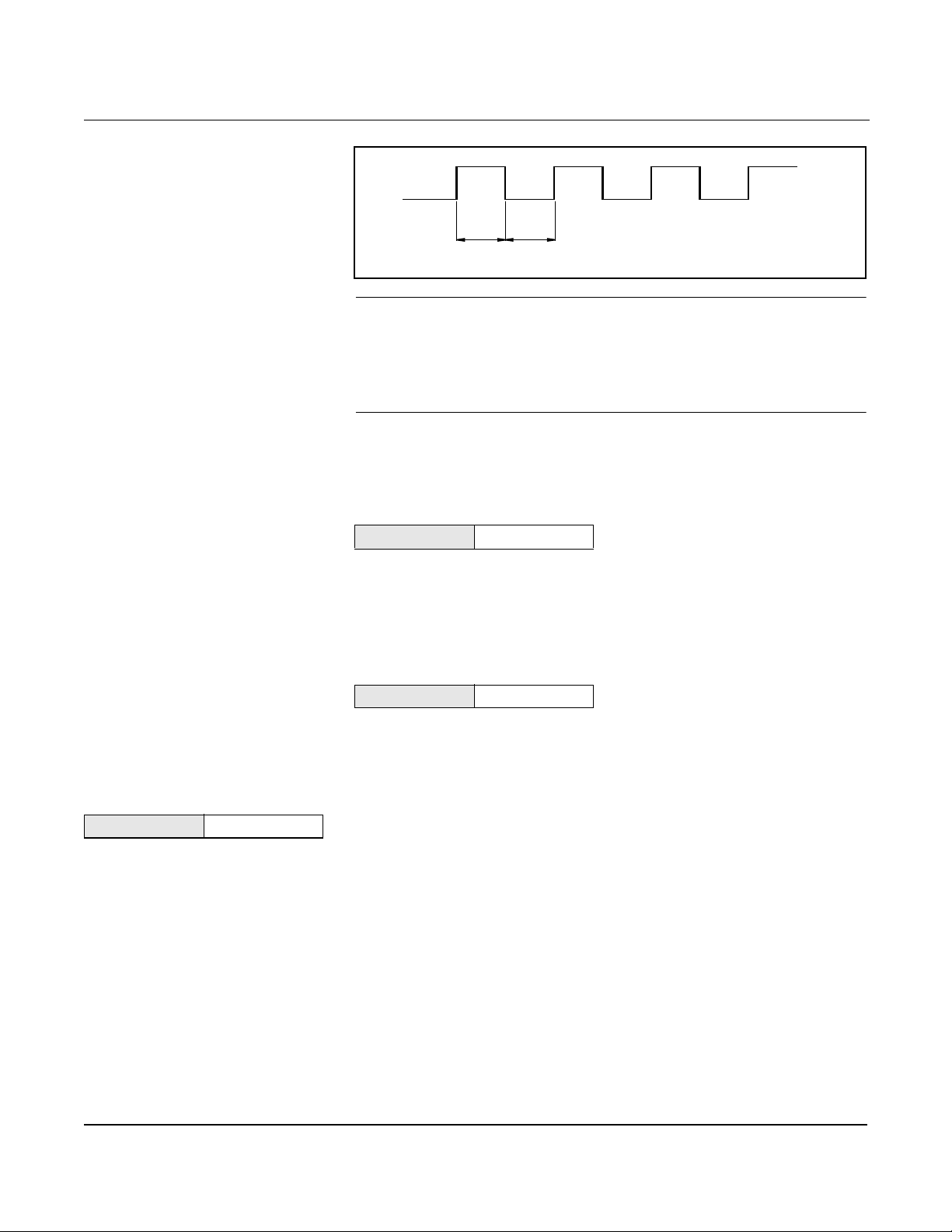
Figure 3-1. Example: The pulse output will maintain a 50 percent duty cycle for all frequencies
Operation
50% Duty Cycle
8800-0546a
NOTE
The scaled pulse output is designed to operate between 0 and 10,000
Hz. The electron ics wil l not acc ept a conve rsion f act or that woul d r esult
in a pulse frequency outside that range. Determine the minimum
conversion factor value by dividing the upper range value (in units of
volume per second) by 10,000 Hz.
The best choice for this parameter depends on the required resolution,
the number of digits in the totalizer, the extent of range required, and
the maximum counter input f requency.
Direct (Shedding Frequency)
HART Comm. 1, 4, 3, 2, 1, 3
This mode provides the vort ex shedding frequency as output. In this
mode, the software does not compensate the K-factor for effects such as
thermal expansion or differing mating pipe inside diameters. Scaled
pulse mode must be used to com pensate the K-factor fo r thermal
expansion and mating pipe effects.
Pulse Output Test
HART Comm. 1, 4, 3, 2, 2
Pulse Output Test is a fixed frequency mo de test that checks the
integrity of the pulse loop. It tests that all connections are good and
that pulse output is runn ing on the loop.
HART Output Multidrop configuration refers to the connection of several flowmeters
HART Comm. 1, 4, 3, 3
to a single communicati ons transmission line. Communication occurs
digitally between a HART-based communicator or control system and
the flowmeters. Multidrop mode automatically deactivates analog
output of the flo wmeters . Using t he HART communic ations p rotocol, u p
to 15 transmitters can be connected on a single twisted pair of wires or
over leased phone line s.
The use of a multidrop ins tallation re quires cons iderati on of the update
rate necessary from each transmitter, the combination of transmitter
models, and the length of the transmission line. Multidrop installations
are not recommended where intrinsic safety is a requirement.
Communication with the transmitters can be accomplished with
commercially available Bell 202 modems and a host implementing the
HART protocol. Each trans mi tter is identified by a unique add ress
(1-15) and responds to the com mands defined in the HART protocol.
3-17
Page 66
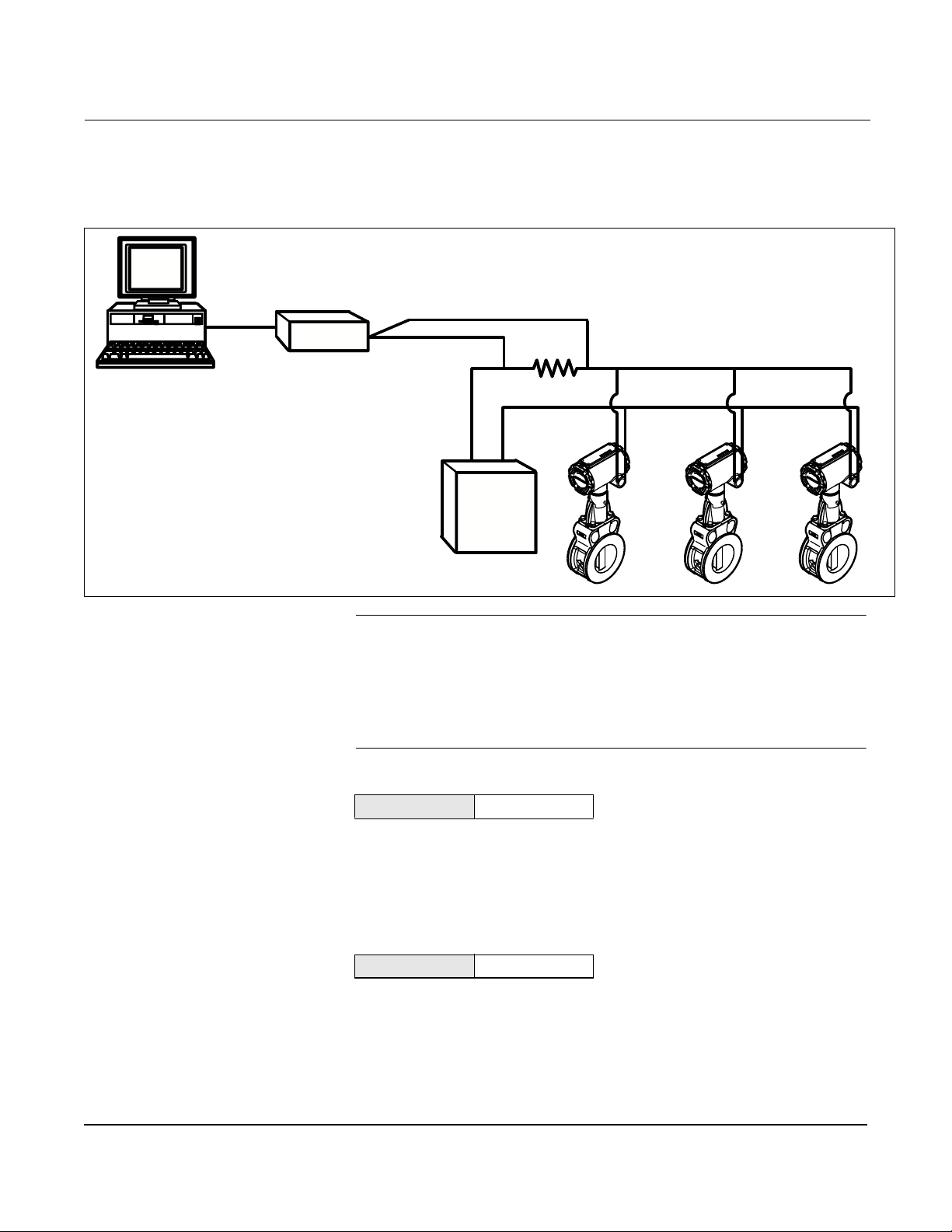
Rosemount Model 8800C Vortex Flowmeter
Figure 3-2 shows a typical multidrop network. This figure is not
intended as an installation diagram. Contact Rosemount product
support with specific requirements for multidrop applications.
Figure 3-2. Typical Multidrop Network
RS-232-C
Bell 202
Modem
Power
Supply
3051-0087B
NOTE
The Model 8800C is set to poll address ze ro at t he fac tory, allowing it to
operate in the sta n d ard poin t- to-poin t m a n n er with a 4–20 mA output
signal. To activate mu ltidrop communication, the transmitter p oll
address must be changed to a number between 1 and 15. This change
deactivates the 4–20 mA analog output, setting it to 4 mA, and di sables
the failure mode alarm signal.
3-18
Poll Address
HART Comm. 1, 4, 3, 3, 1
Poll Address enables you to set the poll address for a multi-dropped
meter. The poll address is used t o ident ify each m eter on th e mult i- drop
line. Follow the on- screen instructions to set the address at a number
from 1 to 15. To set or change the flowmeter address, establish
communication with the selected Model 8800C in the loop.
Auto Poll
HART Comm. OFF LINE FCN
When a HART-based commu nicator is powered up and auto polling is
on, the communicator automatically polls the flowmeter addresses to
which it is connect ed. If the address is 0, the HART-based
communicator enters its normal online mode. If it detects an address
other than 0, the communicator finds each device in the loop and lists
them by poll address and tag. Scroll through the list and select the
meter with which you need to communicate.
Page 67
Operation
If Auto Poll is off, the flow m eter must have the poll address set to 0 or
the flowmeter will not be found. If a single connected device has an
address other than zero and auto polling is off, the device will not be
found either.
Burst Mode Configuration
The Model 8800C includes a burst mode function that broadcasts the
primary variable or all dynamic variables approximately three to four
times a second. The burst mode is a special ized function used in very
specific applications. The burst mode function enables you to select the
variables to broad cast over the burst mode and to select the burst
mode option.
Burst Mode
HART Comm. 1, 4, 3, 3, 3
The Burst Mode variable enables you to set the Burst Mode to the
needs of your applicatio n. Options for the Burst Mode setting inc lude:
Off–Turns off the Burst M ode so that no data are broadcast on the loop.
On–Turns Burst Mode on so that the data sele cted under Burst Option
are broadcast over the loop.
Additional command options may appear that are reserved and do not
apply to the Model 8800C.
Burst Op tion
HART Comm. 1, 4, 3, 3, 4
Burst Option enables you to select the variables to broadcast over the
burst transmitter. Choose one of the following options:
PV–Selects the process variable for broadcast over the burst
transmitter.
Pe rcent Range/Curre nt–Selects the proces s variable as per cent of r ange
and analog output variables for broadcast over the burst transmitter.
Process vars/crnt–Selects the process variables and analog output
variables for broadcast over the burst transmitter.
Local Display
HART Comm. 1, 4, 3, 4
The Local Display function on the Model 8800C allows you to select
which variables are shown on the optional (M5) local display. Choose
from the following variables:
• Flow
• Percent of Range
• Output Current
• Total
3-19
Page 68
Rosemount Model 8800C Vortex Flowmeter
Signal Processing The Model 8800C and its HART-based communications feature enable
HART Comm. 1, 4, 4
you to filter out noi se and other frequencies from the transmitter
signal. The four user-alterabl e p aram eters associated wit h the digital
signal processing on the M odel 8800C include low-pass fi lter corner
frequency, low-flow cutoff, trigger level, and damping. These four signal
conditioning functions are configured at the factory for optimum
filtering over the range of flow for a given line size and service type
(liquid or gas). For most applications, leave these parameters at the
factory settings. Some applications may require adjustment of the
signal processing parameters.
Use signal proce ssing on ly w h en recom mended in th e Troubl es hooting
section of this manual. Some of the problems that may require signal
processing include:
• High output (output saturation)
• Err a ti c output wi th or witho u t fl ow presen t
• Incorrect output (with known flow rate)
• No output or low output with flow present
• Low total (missing pulses)
• High total (e xt ra pulse s)
If one or more of these conditions exist, and you have checked other
potential sources (K-factor, service type, low er and upper range values,
4–20mA trim, pulse scaling factor, process temperature, pipe ID), refer
to Section 4: Hardware and Software Maintenance and
Troubleshooting procedures. Remember that the factory default
settings can be re-established at any time with Filter Restore.
If problems persist after signal processing ad justments, consult
the factory.
3-20
Optimize Flow Range
HART Comm. 1, 4, 4, 1
Optimize Flow Range affects the follow ing variables:
• Flow
• Low Flow Cutoff
• Sig/Tr
• Auto Adjust Filter
Flow
HART Comm. 1, 4, 4, 1, 1
Flow is the ac tual m easured fl ow rat e in t he li ne. On the be nch, th e PV
value should be zero. Check the units on the PV to make sure they are
configured correct ly. See PV Units if the units format is not corr ect. Use
the Process Variable Units function to select the units for
your application.
Low Flow Cutoff
HART Comm. 1, 4, 4, 1, 2
Low Flow Cutoff is shown in engineering units.
Page 69
Operation
Sig/Tr (Signal/Trigger Level Ratio)
HART Comm. 1, 4, 4, 1, 3
The Signal to Trigger Level Ratio is a variable that indica tes the
flow signal strength to trigger level ratio. This ratio indicates if there is
enough flow signal strength for the meter to work properly. For
accurate flow measurement, the ratio should be greater than 4:1.
Values greater that 4:1 will allow increased filtering for noisy
applications. F or ratios greater than 4:1, with sufficient density, the
Auto Adjust Filter funct ion can be utilized to optimize the
measurable range of the fl ow me ter.
Ratios less than 4:1 may indicate applications wit h very low densities
and/or applications with excessive filtering.
Auto Adjust Filter
HART Comm. 1, 4, 4, 1, 4
The Auto Adjust Filter is a function that can be used to optimize the
range of the flowmeter based on the density of the fl uid. The electroni cs
uses process density to calculate the minimum measurable flow rate,
while retaining at least a 4:1 signal to the trigger level ratio. This
function will also reset all of the filter s to optimize the flowmete r
performance over the new range.
Manual Filter Adjust
HART Comm. 1, 4, 4, 2
Manual Filt er Adjus t allows you to manually adjust the following
settings: Low Flow Cutoff, Low Pass Filter, and Trigger Level, while
monitoring flow and or sig/tr.
Flow
HART Comm. 1, 4, 4, 2, 1
Flow is the ac tual m easured fl ow rat e in t he li ne. On the be nch, th e PV
value should be zero. Check the units on the PV to make sure they are
configured correct ly. See PV Units if the units format is not corr ect. Use
the Process Variable Units function to select the units for your
application.
Sig/Tr (Signal/Trigger Level Ratio)
HART Comm. 1, 4, 4, 2, 2
The Signal to Trigger Level Ratio is a variable that indica tes the
flow signal strength to trigger level ratio. This ratio indicates if there is
enough flow signal strength for the meter to work properly. For
accurate flow measurement, the ratio should be greater than 4:1.
Values greater that 4:1 will allow increased filtering for noisy
applications. F or ratios greater than 4:1, with sufficient density, the
Optimize Flow Range function can be utilized to optimize the
measurable range of the fl ow me ter.
Ratios less than 4:1 may indicate applications wit h very low densities
and/or applications with excessive filtering.
3-21
Page 70
Rosemount Model 8800C Vortex Flowmeter
Low Flow Cutoff
HART Comm. 1, 4, 4, 2, 3
Low Flow Cutoff enables you to adjust the filter for noise at no flow. It
is set at the factory to handle most applications, but certain
applications ma y require adj ust ment eit her to expand measur abilit y or
to reduce noise.
The Low Flow Cutoff offers two modes for adjustment:
• Increase Range
• Decrease No Flow Noise
It also includes a dead band such that once flow goes below the cutoff
value, output does not return to the normal flow range until flow goes
above the dead band. The dead band extends to approximately 20
percent above the low flow cutoff value. The dead band prevents the
output from bouncing between 4mA and normal f low range if the flow
rate is near the low flow cutoff value.
Low Pass Filter
HART Comm. 1, 4, 4, 2, 4
The Low Pass Filter sets the low-pass filter corner frequency to
minimize the effect s of high frequency noise. It is factory set based
on line siz e and servic e type. Adju stments m ay b e re q u ired only if
you are experiencing problems. See Section 4: Troubleshooting
and Maintenance.
The Low Pass Filter corner frequency variable offers two modes for
adjustment:
• Increase filtering
• Increase sensitivity
Trigger Level
HART Comm. 1, 4, 4, 2, 5
Trigger Level is configured to reject noise w ithin the flow range while
allowing normal amplitude variation of the vortex signal. Signals of
amplitude lower than the Trigger Level setting are filtered out. The
factory setting optimizes noise rejection in most applications. Trigger
Level offers two modes for adjustment:
• Increase filtering
• Increase sensitivity
NOTE
Do not adjust this parameter unless directed to do so by a Rosemount
Technical Support Representative.
3-22
Page 71
Operation
Filter Restore
HART Comm. 1, 4, 4, 3
Filter Restore enables yo u to return al l of th e signal co n d itionin g
variables to t heir defa ult values . Shoul d the filter settings get confused,
select Filter Restore to restore the default settings and provide a new
starti ng point.
Damping
HART Comm. 1, 4, 4, 4
Damping functi on ch a nges the respons e ti m e of the flow meter to
smooth variatio ns in output readi ngs caused by rapi d c hanges in i nput.
The default damping value is 2.0 seconds. Damping can be reset to any
value between 0.2 and 256 seconds.
The appropriate damping set ting can be determined based on the
necessary res ponse ti me, si gnal st abil ity, and other requi rements of the
loop dynamics in your system.
Process Density
HART Comm. 1, 4, 4, 5
Process Density and Density Units are required only if you have
designated mass units for your flow rate units. See Process Density on
page 3-7 or detailed information.
Device Information Information variables are used for identifi cation of flowmeters in the
HART Comm. 1, 4, 5
field and to store information that may be useful i n service situations.
Information variables have no effect on flowmeter output or
process variables.
Manufacturer
HART Comm. 1, 4, 5, 1
Manufacturer is an informational variable provided by the factory.
For the Model 8800C , the Ma nufacturer is Rosemount.
Tag
HART Comm. 1, 4, 5, 2
Tag is the quickest variable to identify and distinguish between
flowmeters . Flowmete rs c an be tagged acco rdi ng to the requi rement s of
your application. The tag may be up to eight characters long.
Descriptor
HART Comm. 1, 4, 5, 3
Descriptor is a longer user-defined variable to assist with more
specific ide ntification of the particular flowmete r. It is usually used in
multi-flowmeter environments and provides 16 characters.
3-23
Page 72
Rosemount Model 8800C Vortex Flowmeter
Message
HART Comm. 1, 4, 5, 4
The Message variable provides an even longer user-defined variabl e
for identification and other purposes. It provides 32 characters of
information and is stored with the other configuration data.
Date
HART Comm. 1, 4, 5, 5
Date is a user-defined variable that provides a place to save a date,
typically used to store the last date that the transm itter configuration
was cha nged.
Write Protect
HART Comm. 1, 4, 5, 6
Write Protect is a read-onl y informational vari able that reflects the
setting of the hardware security switch. If Write Protect is ON,
configuration data are protected and cannot be changed from a
HART-based communicator or control system. If Write Protect is OFF,
configuration data may be changed using the communicator or control
system.
Revision Numbers
HART Comm. 1, 4, 5, 7
Revisions Numbers are fixed informational variables that provide
the revision number for different elements of your HART
Communicator and Model 8800C. These revision numbe rs may be
required when calling the factory for support. Revision numbers can
only be changed at the factory and are provided for the following
elements:
Universal Rev
HART Comm. 1, 4, 5, 7, 1
Universal Rev – Designates the HART Universal Command
specif ic a tion to whic h the tran smitter is d e signed to co n fo rm.
Transmitter Rev
HART Comm. 1, 4, 5, 7, 2
Tran smitter Re v – Designates the revision for Model 8800C specific
command identification for HART compatibility.
Software Rev
HART Comm. 1, 4, 5, 7, 3
Software Rev – Designates the internal software revision level for the
Model 8800C.
3-24
Page 73
Operation
Hardware Rev
HART Comm. 1, 4, 5, 7, 4
Hardware Rev – Designates the revision level for the Model
8800C hardware.
Final Asse mbly Number
HART Comm. 1, 4, 5, 7, 5
Final Assembly Number – Factory set number that refers to the
electronics of your flowmeter. The number is configured into the
flowmeter fo r later reference .
Device ID
HART Comm. 1, 4, 5, 7, 6
Device ID – Factory-defined unique identifier for transmitter
identification in the software. Device ID is not user c hangeable.
3-25
Page 74

Rosemount Model 8800C Vortex Flowmeter
3-26
Page 75

Section
4 Hardware and Software
Maintenance and
Troubleshooting
Safety Messages . . . . . . . . . . . . . . . . . . . . . . . . . . . . . . . . page 4-1
Troubleshooting Tables . . . . . . . . . . . . . . . . . . . . . . . . . . . page 4-3
Advanced Troubleshooting . . . . . . . . . . . . . . . . . . . . . . . . page 4-6
Testing Procedures . . . . . . . . . . . . . . . . . . . . . . . . . . . . . . page 4-9
Hardware Replacement . . . . . . . . . . . . . . . . . . . . . . . . . . .page 4-10
Return of Material . . . . . . . . . . . . . . . . . . . . . . . . . . . . . . . .page 4-27
Table 4-1 provides summari zed troubleshooting suggestions for the
most common problems that occur during operation. The symptoms of
metering problems include:
• Communications problems with a HART-based communicator.
• Incorrect 4–20 mA output.
• Incorrect pulse output.
• Error messages on HART-based communicator.
• Flow in pipe but no transmitter output.
• Flow in pipe with incorrect transm itter output.
• Output with no actual flow.
NOTE
The Model 8800C sensor is extremely r eliable and sho uld not ha ve to be
replaced. Please consult the factory before removing the sensor.
SAFETY MESSAGES Instructions and procedures in this section may require special
precautions to ensure the safety of the personne l performing the
operations. Please refer to the following safety messages before
performing any in this section.
4-1
Page 76
Rosemount Model 8800C Vortex Flowmeter
Explosions could result in death or serious injury:
Failure to f ollow these installation guidelines could result in death or serious injury:
• Make sure only qual i fied personnel perform the installation.
• Do not remove the tr ansmi tte r cov e r in e xpl os iv e atmo spher es wh en the c ircuit
is alive.
• Before connecting a HART-based communicator in an explosive atmosphere,
make sure the instruments in the loop are installed in accordance with
intrinsically safe or non-i ncendive field wiring pr actices.
• V eri fy that the operat i ng atmosphere of the transmitter i s consistent with the
appropriate hazardous locations certifi cations.
• Both transmitter covers must be fully engaged to meet explosion-proof
requirements.
The sensor cavity could contain line pressure if an abnormal failure has occurred inside
the meter body. Depressurize flow lin e before removing the sensor nut.
4-2
Page 77

Hardware and Software Maintenance and Troubleshooting
TROUBLESHOOTING TABLES
The most common problems experienced by users of the Model 8800C
are listed in Table 4-1 along with potentia l causes of the problem and
suggested correc tive actions. See Adva nced Troubleshooting on page
4-6 if the problem you are experiencing is not listed here.
Table 4-1. Basic Troubleshooting - Model 8800C Smart Vortex Flowmeter
Symptom Corrective Action
Communication
problems with
HART-based Communicator
Incorrect 4–20 mA Output
Incorrect Puls e Ou tp ut
Error Messages on
HART-based Communicator
Flow in Pipe, No Output Basics
• Check f or a mi nimum of 12 V dc at transmitter
terminals.
• Check communi cations loop with HART-based
communicator.
• Check for l oop resistor (250 to 1000 ohms).
• Check for transmitter in multidrop mode.
• Check for 12 V dc at transmitter terminal.
• Check URV, LRV, Density, Special Units, LFC–
compare these in puts with the sizing program
results. Correct configuration.
• Perfo rm 4–20 mA loop test.
• Check that 4–20 mA output is correct.
• Check pulse counter specifications.
• Check pulse mode and scaling factor. (Make sure
scaling factor is not inverted).
• See alphabetical listing in the Error Messages
Tabl e for the comm unicator in Appendi x C: HART
Communicator.
• Check to mak e t he s ure that the met er is i nst alle d
with th e a rr ow in th e di r e c ti on of proc ess flow.
• Perform basic checks for Incorrect 4–20 mA
Output Problem (see Incorrect 4–20 mA Output).
• Check and correct configuration parameters in
this order:
K-factor, service type, materials, units, process
temperature, damping value, 4–20 mA trim,
meter body number, density, pulse mode, pulse
scaling, line size, pipe diameter, LRV, URV, LP
corner, trigger level, low flo w cutoff.
• Check sizing. Make sure flow is within
measurable flow limits.
• Refer to Advanced Troubleshooting on page4-6.
• See Appendix E: Electronics Verification for
electronics verification pro cedure.
Electronics
• Run a self test with the Model 268/HART
Communicator.
• Using sensor simul ator, ins ert test s i gnal.
• Check configuration, LFC, trigger level, STD vs.
actual flow.
• Replace electronics.
• Check for transmitter in burst m ode.
• Remove pulse connection if you have a three wire
pulse installation.
• Replace electronics.
• Check for corrosion on terminal block.
• Replace electronics if necessary.
• Refer to Advanced Troubleshooting on page 4-6.
• See Appendix E: Electronics Verification for
electroni cs verification procedure.
• Perform pulse test.
• Select pulse scaling so that pulse output is less
than 10,000Hz at URV (Model 8800C only).
Application Problems
• Calculate expected frequ ency (see Appendix E:
Electronics Verification). If actual f req uency i s the
same, check configuration.
• Check that application meets viscosity and
speci fi c grav i ty requir em ents for the li n e si ze.
• Recalculate back pressure requirement. If
necessary and possible, in crease back pressure,
flow rate, or operating pre ssure.
Sensor
• Check torque on sensor nut (32 ft-lb).
• Inspect coaxial sensor cable for cracks. Replace
if necessary.
• Check that sensor impedance >10 Megohms.
Replace sensor if necessary (Rep l a c i ng t h e
Sensor on page 4-15).
• Measure sensor capacitance at SMA connector
(100–200pF).
4-3
Page 78

Rosemount Model 8800C Vortex Flowmeter
Symptom Corrective Action
Flow in Pipe,
Incorrect Output
Basics
• Perform basic checks for Incorrect 4–20 mA
Output Prob lem (see Incorrect 4–20 mA Output
on page 4-3).
• Check and correct configuration parameters i n
this order:
K-factor, service type, materials, units, process
temperature, damping val ue, 4–20 mA trim,
meter body number, density, pulse mode, pulse
scaling, line size, pipe diameter, LRV, URV, LP
corner, trigger level, and low flow cutoff.
• Check sizi ng. Make sure flow is within
measurable flow limits.
• Refer to Advanced Troubleshooting on page 4-6.
• See Appendix E: Electronics Verification for
electroni cs verification procedure.
Application Problems
• Calculate e xp ecte d fre quenc y. If actual freq uen cy
is the same, check configu ration.
• Check to make sure the meter is not installed
backwards (Arrow on meter pointing upstream is
backwards). Re-install the meter if necessary.
• Check that application mee ts viscosity and
specific gravity requirement s for the line size.
• Recal culate back pres sure re quire ment. If ne cessary
and possible, increase back pressure, flow rate, or
operating pressure.
• Check for gasket or other obstruction disturbing
flow. Reinstall meter if necessary.
• Pump pulsations disturbing flow. Adjust signal
processing parameters.
Vibration Problem
• Adjust signal processing parameters.
• Rotate me ter 90 degrees.
• Add support to the line nea r the meter to damp
the vibration.
When the v ortex meter is set for gas or steam se rvice
and the vibr ation l e v el s are gr eat er than ½ g, the Low
Flow Cutoff value (LFC) may need to be increased to
eliminate undesirab l e output at no flow conditions.
The level of LFC increase depends on the vibration
lev el and meter size. LFC is unique f or each
application. When flow begins, the flow signal
become s much larger t h an t he vi br ation sign al and
the meter will lock onto the flow signal and give an
accurate flow output.
50/60 Hz Measurem ent
• Make sure electronics mounting s crews (3) are
securely installed.
• May indicate electrical or magnetic interference.
Check meter g r ound. Measure voltage levels
between 4–20 mA and pulse outputs and the
electronics housing. Common mode
voltage < 30 Vrms.
• If the meter is loca te d nea r a larg e moto r or
electric furnace try different meter ori entations to
reduce the noise. Magnetic fields must be less
than 5 gauss .
• In remote moun t ins t all a tio ns, try integral mou n t
to see if problem is corrected. Measure ac
voltage from electroni cs housing to SMA
connector. The v ol tage must be <1Vrms .
Sensor
• Sensor should resist removal because the
interference fit has extremely tight tolerances.
Repeated removal and installation of the sensor
will loosen it. If sensor is loose, replace the
sensor.
• Inspect and tighten sensor connector if
necessary.
• Inspect coaxial sensor cable for cracks. Replace
if necessary.
• Check torqu e on sensor nut (32 ft-lb).
• Check that sensor impedance >10 Megohms.
Replace sensor if necessary (see Repl acing the
Sensor on page4-15).
• Measure sensor capacitance at SMA connector.
(100–200pF)
4-4
Page 79

Symptom Corrective Action
Output with No Actual Flow Basics
• Perform basic checks for Incorrect 4–20 mA
Output Prob lem (see Incorrect 4–20 mA Output
on page 4-3).
• Check and correct configuration parameters i n
this order:
K-factor, service type, materials, units, process
temperature , dampi ng v al ue ,4 –20 mA trim, meter
body number, dens ity, pulse mode, pulse s cali ng,
line size , pipe diameter, LRV, URV, LP corner,
trigger level, low flow cutoff.
• Check sizi ng. Make sure flow is within
measurable flow limits.
• Using a HART-based communicat or, read the
shedding fr equency.
• Refer to Advanced Troubleshooting on page 4-6.
Hardware and Software Maintenance and Troubleshooting
50/60 Hz Measurem ent
• Make sure electronics mounting s crews (3) are
securely installed.
• May indicate electrical or magnetic interference.
Check meter g r ound. Measure voltage levels
between 4–20 mA and pulse outputs and the
electronics housing. Common mod e voltage <30
Vrms.
• If the meter is loca te d nea r a larg e moto r or
electric furnace try different meter ori entations to
reduce the noise. Magnetic fields must be less
than 5 gauss .
• In remote moun t ins t all a tio ns, try integral mou n t
to see if problem is corrected. Measure ac
voltage from electroni cs housing to SMA
connector. The v ol tage must be <1Vrms .
Vibration Problem
• Adjust signal processing parameters:
Adjust low flo w cutoff to higher flow rates (if th e
application allows). Move the low flow cutoff up
one notch and measure the process variable.
Continue moving the low flow cutoff
until the problem is correct ed or the flow range i s
too limited for the application.
Adjust the trigger l evel up; t he de f ault trigger le v el i s
four . Adj ust it one notch and measure the proces s
variable. Continue mov ing the trigger level until t he
output reaches zero or the trigger le v el reaches a
value of se v en. Be sure to c hec k the proce ss
variable with the process flo wing once you are done
adjusting the
trigger level.
• Rotate the meter 90 degrees.
• Add support to the line nea r the meter to damp
the vibra ti on.
Application Problems
• Pump pulsations disturbing flow. Adjust signal
processing parameters.
• Add flow straightener.
• Check all valves and make sure they are closed.
4-5
Page 80
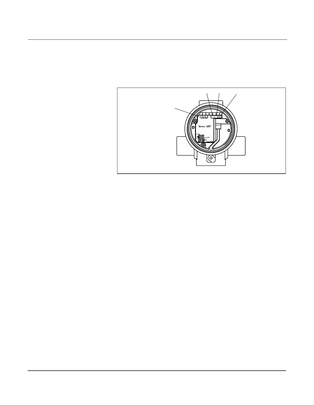
Rosemount Model 8800C Vortex Flowmeter
ADVANCED TROUBLESHOOTING
Figure 4-1. Electronics Test Points
The Model 8800C electronics provides several advanced
troubleshooting features. These features enhance your abili ty to look
inside the electronics and can be helpful for troubl eshooting inaccurate
readings . As shown in Figure 4-1, there are several test points located
on the electronics.
GND
Shedding Freq Out
TP1
Test F req IN
A digital represe n tation of the filtered sensor shedding frequency is
available on the “SHEDDING FREQ OUT” pins shown in Figure 4-1.
The electronics are capable of internally gener ating a flow signal that
may be used to simulate a sensor signal to perform electronics
verification wit h the Model 275 or AMS inte rface . The simul ated s ignal
amplitude is based on the transmitter required minimum process
density. The signal being simulated can be one of several profiles – a
simulated signal of constant frequency or a simulated si gnal
representati ve of a ram ping flow rate. The electronics verification
procedure is d escr ibed in d etai l in Appen dix E: Ele ctroni cs Verification.
To verify the electroni cs, y ou can input a f requency on the “TEST FREQ
IN” and “GND” pins to simulate flow via an external si gnal source suc h
as a frequency generato r. To analyz e and/or troubleshoot the
electronic s, an oscilloscope (set for AC coupling) and a Model 275 or
AMS interface are required. Figure 4-2 is a block diagram of the signal
as it flows from th e sensor to the microprocessor in the electronics.
8800-0000A04C
4-6
Page 81
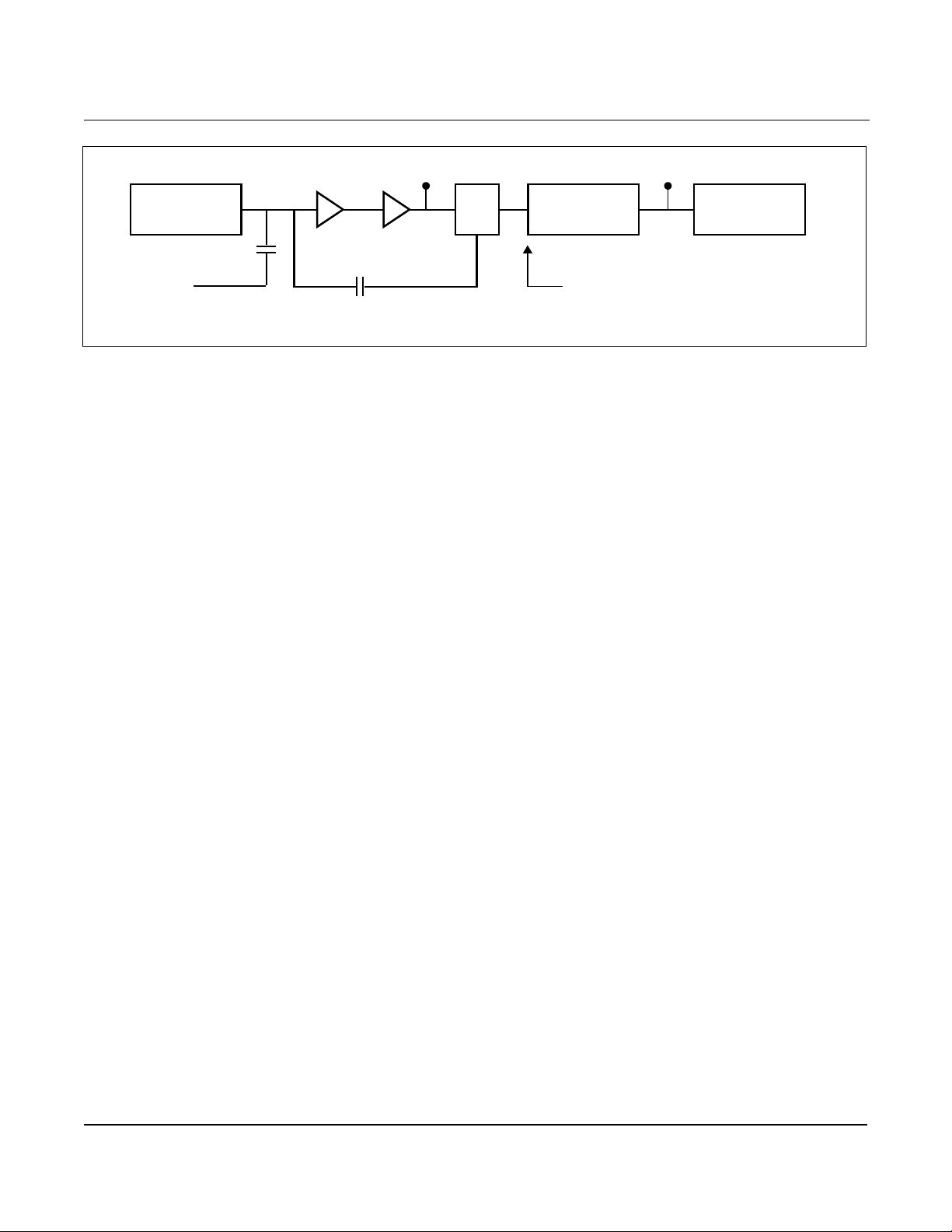
Figure 4-2. Signal Flow
Sensor
Hardware and Software Maintenance and Troubleshooting
TP1 Shedding Frequency Output
Digital Filter
Microprocessor
Charge
Amplifier
External
Test
Frequency
Input
Amplifier/
Low Pass
Filter
A-to-D Converter
Containing Frequency
Generator
TP1 TP1 is the vortex shedding signal after it has gone through the charge
amplifier and low pass filter stages and into the input of the sigma delta
A-to-D converter ASIC in the electronics. The signal strength at this point
will be in the mV to V olt range.
TP1 is easily measured with standard equipment.
Figures 4-3, 4-4, and 4-5 show ideal (clean) waveforms and waveforms
that may c ause the output t o be inac curat e. Pl ease c onsul t the f act ory i f
the waveform you detect is not similar in principle to these waveforms.
8800-0572D
4-7
Page 82
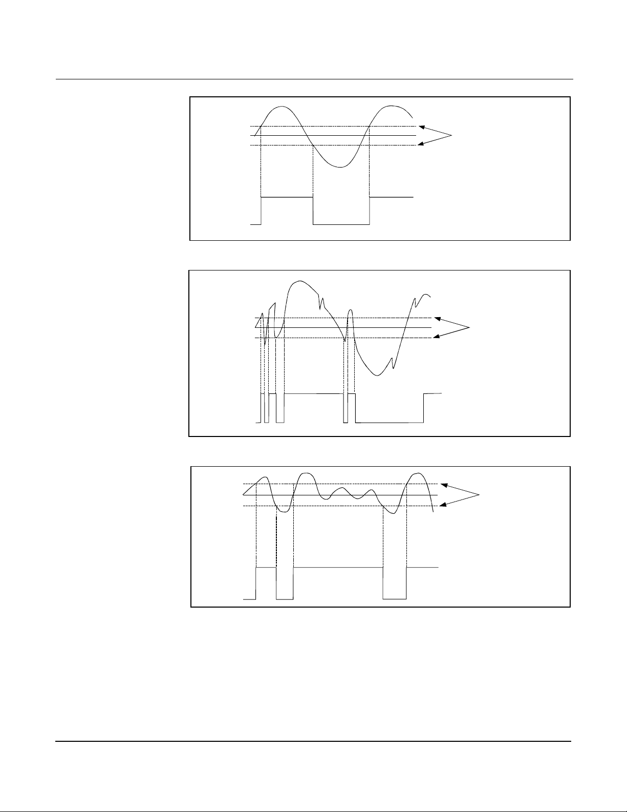
Rosemount Model 8800C Vortex Flowmeter
Figure 4-3. Clean Signals
0
3.45 V
0
Figure 4-4. Noisy Signals
Vortex Signal (TP 1 )
Trigger
Level
Shedding
Frequency
Output
8800-0572A
Vortex Signal
(TP1)
Figure 4-5. Improper Sizing/Filtering
3.45 V
0
3.45 V
0
0
0
V ortex Signal
(TP1)
Shedding
Frequency
Output
Trigger
Level
Shedding
Frequency
Output
8800-0572B
Trigger
Level
8800-0572C
4-8
Page 83

Hardware and Software Maintenance and Troubleshooting
Shedding Fre quency Out Shedding frequency out is probably the easiest point to measur e and
interpret. It is the final waveform after all filtering has taken place. It
is the flow signal that is sent to the microprocessor to be processed into
outputs. C h ec k th i s point fir st , as it w ill allow you to see the fina l
waveform (after filtering) before it goes to the microprocessor.
Symptom Corrective Action
Clean Signals at TP1 and
Shedding Frequency Out, But
Incorrect Output
No Pulse at
Shedding Frequency Out
Noisy Signal at
Shedding Frequency Out
Missing Pulses at
Shedding Frequency Out
Basics
• Perform basic checks f or incorrect 4–20 mA
output probl em (see Basic Troubleshooting Model 8800C Smart Vortex Flowmeter on
page 4-3).
• Perform basic check for pulse output.
• Check and correct configura tion parameter s in
this order:
K-factor, service type, mat eri al s, units, process
temperatur e, damping value, 4–20 mA trim,
filter tracking, density, density ratio, pulse
mode, pulse scaling, line size, pipe diameter,
LRV, URV, LP corner, trigger level, and low flow
cutoff.
Basics
• Check TP1.
• Check elect r onics via Flow Simulation Mode
(see Appendix E: El ectronics Verification).
• Check electronics with frequency ex ternal
generator (see Appendix E: Elec tronics
Verification).
Basics
• Simulate signal with frequency generators or
Flow Simulation Mode (see Appendix E:
Electroni cs Verifica tio n ).
Basics
• Low back pres sure.
• Viscosity too high.
• Density too low.
• Refer to Advanced Troubleshooting on page 4-6.
• See Appendix E: Electronics Verification for
electronics verification procedure.
• Refer to Table 4-1 for further troubleshooting.
• Check that sens or i m pedance >10 Megohms .
Replace sensor if necessary. (See Replacing the
Sensor on page4-15.)
• Measure sensor capacitance at SMA connector
(100–200pF).
• Optimize filter (gas); increase fil tering of low
pass filter.
• Consult factory.
• Check sensor.
• Too much filt ering. Check si gnal/trigger level.
TESTING PROCEDURES U se the tes t fu n c tions to ve r ify that the flowmet er is funct ioning
properly, or when you suspect co mponent f ai lure or a probl em wit h loo p
performance, or when instructed to do so as part of a troubleshooting
procedure. Initiate each test with the HART Communicator or other
HART-based communications device. See Diagnostics/Service on
page 3-3 for details.
4-9
Page 84

Rosemount Model 8800C Vortex Flowmeter
HARDWARE REPLACEMENT
The follo w in g procedures will he lp you disas semble an d as s emble the
Model 8800C hardware if you have followed the trouble shooting guide
earlier in this section of the manual and determined that hardware
components need to be replaced.
NOTE
Failure of the Model 8800 housing, electronics, terminal block, LCD
indicator, or entire assembly requires replacement with the Model
8800C housing, electronics, terminal block and optional LCD indicator.
The Model 8800 can be ide ntifi ed on the SST ta g or by vis ually chec king
to see if the conduit e ntr ies are o n the top of the housin g . See Repla cin g
the Electronics Housing on page 4-13, for further information.
NOTE
Use only the procedures and new parts specifically referenced in this
manual. Unauthorized procedures or parts can affec t product
performance and the output signal used to control a process, and may
render the instrument dangerous. Direct any questions concerning
these procedures or parts to Rosemount Inc.
NOTE
Flowmeters should not be left in service once they have been
determined to be inoperable.
NOTE
Process shoul d be ve nted bef ore t he met er body is r emoved fr om se rvice
for disassembly.
4-10
Page 85
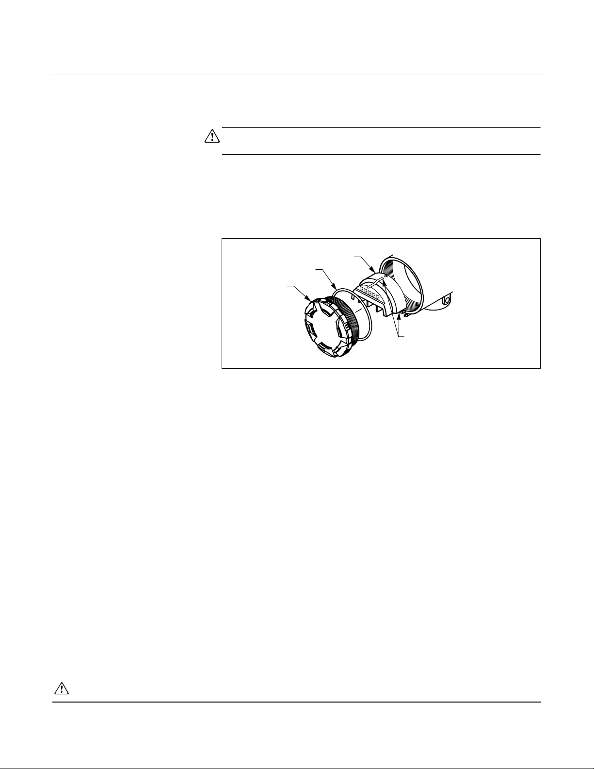
Hardware and Software Maintenance and Troubleshooting
Replacing the Terminal Block in the Housing
Figure 4-6. Terminal Block Assembly
To replace the Field Terminal Bloc k in the housing, you will need a
small, fla t head screwdriver. Use the following procedure to repla ce the
terminal block in the housing of the Model 8800C.
NOTE
Remove power before removing the electron ics cover.
Remove the Terminal Block
1. Turn off the electric power to the Model 8800C.
2. Unscrew the cover.
Terminal Block
O-Ring
Cover
Captive
Screws
8800-0463A01Z
3. Disconnect the wires from the field terminals. Be sure to secure
them out of the way.
4. Remove the ground screw (middle of the terminal block) if
transient protection (Option T1) is installed.
5. Loosen the captive screw s.
6. Pull outward on the blo ck to remove it from the housing.
Install the Terminal Block
1. Align the terminal block over the captive screw holes in the
terminal block side of the electronics housing.
2. Slowly press the terminal block into place. Do not force the
block into the housing. Check the screw alignment if it
does not g l i d e into plac e.
3. Tighten the three captive screws to anchor the terminal block.
4. Connect the wires to the appropriate field terminals.
5. Reinstall and tighten the transient ground screw if you have the
transient option (Option T1).
6. Screw on and tighten the cover.
See Safety Messages on page 4-1 for complete w arn i ng i nformation .
4-11
Page 86
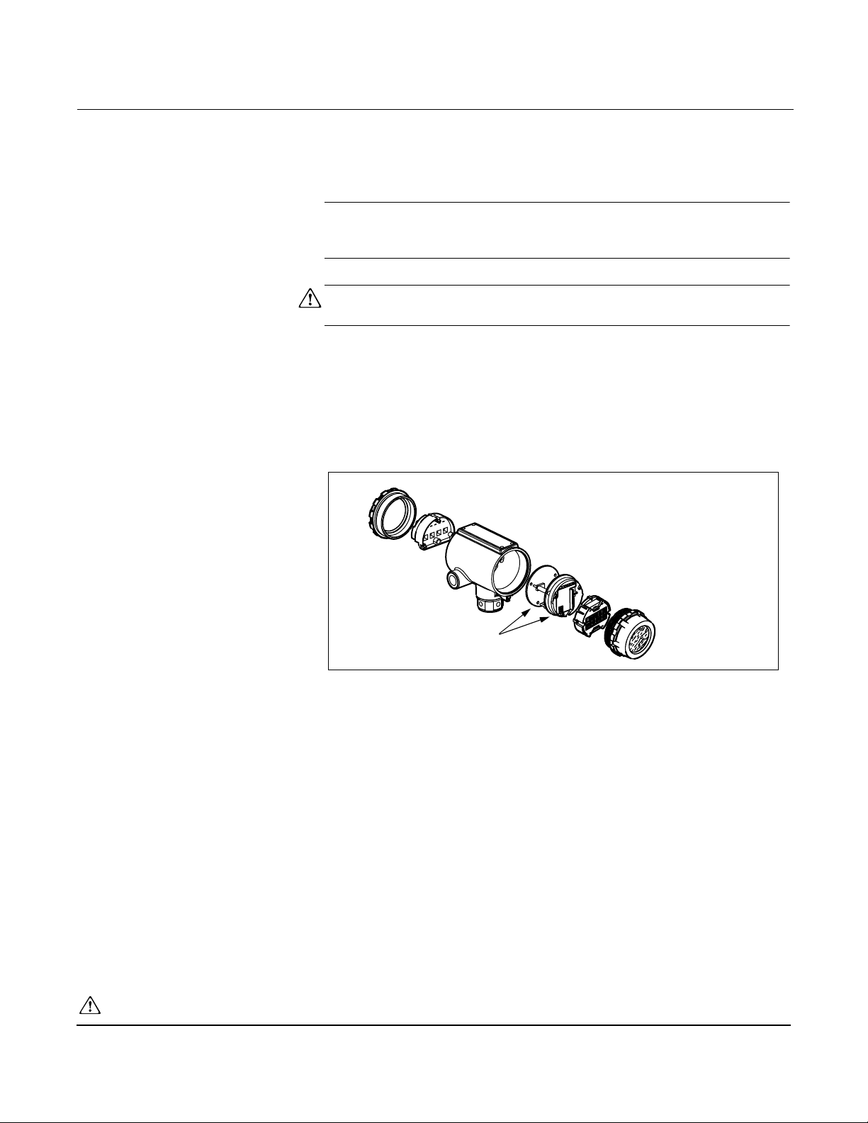
Rosemount Model 8800C Vortex Flowmeter
Replacing the Electronics Boards
Figure 4-7. Electronics Boards Assembly
The Model 8800C electronics boards may need to be replaced if they
have been damaged or otherwise become dysfunctional. Use the
following procedures to replace electronics boards in the Model 8800C.
You will need a small flat head screwdriver and pliers.
NOTE
The electronics boards ar e electros tatica lly sensit ive . Be sure to observe
handling precauti ons for static-sen sitive components.
NOTE
Remove power before removing the electron ics cover.
Remove the Electronics Boards
1. Turn off the electric power to the Model 8800C.
2. Unscrew and remove the electronics board compartment cover.
(Unscrew and remove the LCD cover i f you have the LCD option).
3. If the meter has the LCD indicator option, loosen the two screws.
Remove the LCD and the connector from the electronics board.
4. Loosen the three captive screws that anchor the electronics.
5. Use p liers to ca re fu lly remov e the sens o r ca b le clip
from the electronics.
6. Use the two screw heads on the right- and left-hand sides of the
board to s lo w ly pull th e electron ics boar ds out of th e housing.
See “Safety Messages” on pa ge4-1 for complete w arning information.
4-12
Electron i c s B oards
8800-0000A01A
Page 87

Hardware and Software Maintenance and Troubleshooting
Install the Electronics Boards
1. Verify that elec tric power to the Model 8800C is off.
2. Align the two electronics boards over the captive screw holes
in the housing .
3. Slowly press the boards into place. Do not force the boards down.
Check th e sc rew alig n ment if the y d o n o t glide int o p la ce.
4. Use extreme caution to insert sensor cable clip into the
electronics board.
5. Tighten the captive screw s to anchor the two electronics boards.
6. Reinsert jumpers into proper location.
7. If the meter has LCD option, insert the connector header int o the
LCD board.
• Put the connector through the bezel on the electronics board set.
• Carefully press the indicator onto the connector.
• Tighten the two screws that retain the L CD indicator.
• Insert the alarm and security jumpers in the correct location.
8. Replace the electronics board compartment cover.
Replacing the Electronics Housing
The Model 8800C electronic s housing can be replaced easily when
necessary. Use the following procedur e:
Tools Needed
•5/32-inch (4 mm) hex wrench
•5/16-inch open end wrench
• Screwdriver to disconnect wires
• Tools to disconnect conduit
NOTE
Remove power before removing the electron ics housing.
Remove the Electronics Housing
1. Turn off the electric power to the Model 8800C.
2. Disconnect the wires and conduit from the housing.
3. Loosen the screw on the access cover (on the support tube).
See Figure 4-8.
4. Remove the access cover.
See Safety Messages on page 4-1 for complete w arn i ng i nformation .
4-13
Page 88
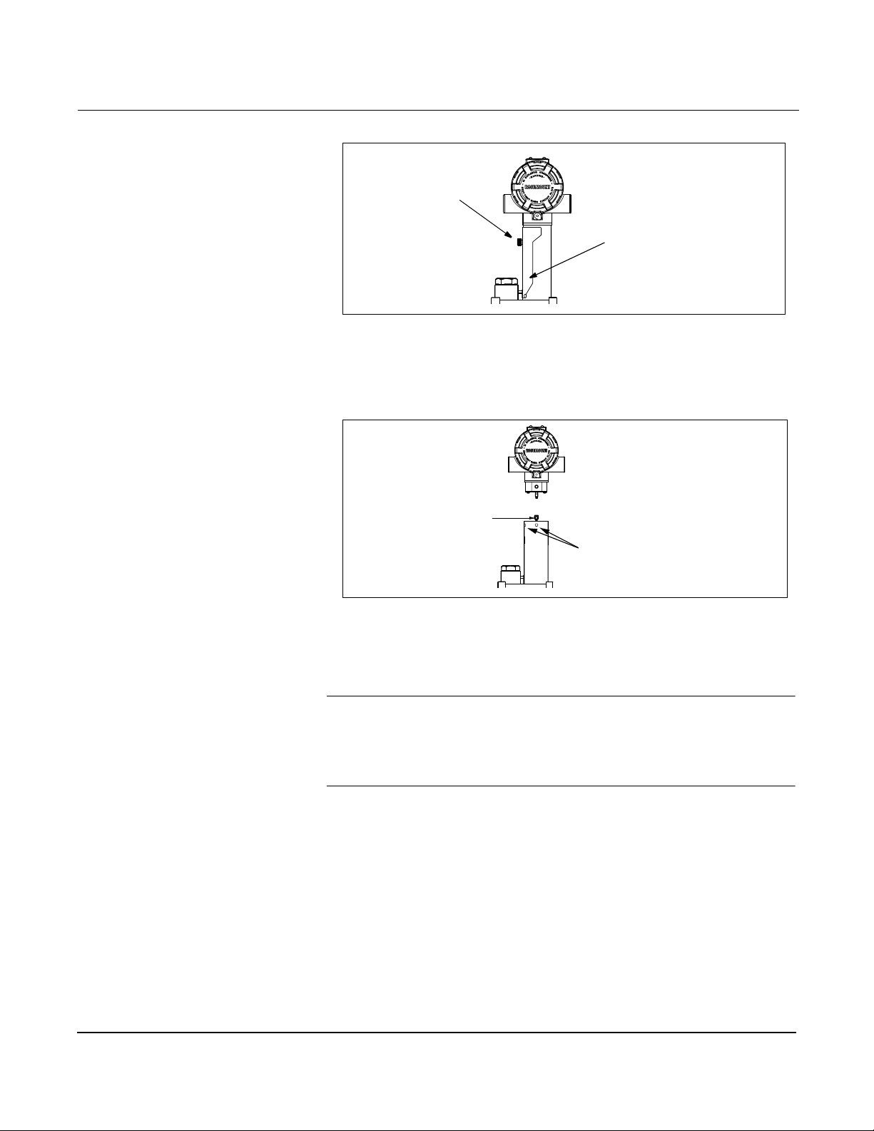
Rosemount Model 8800C Vortex Flowmeter
Figure 4-8. Electronics Housing Access Cover
5. Use a hex wrench to loosen the housing rotation screws (at the
base of the electronics housing) by turning screws clockwis e
(inward) until they will clear the bracket.
Figure 4-9. Housing Rotation Screws
Access
Cover
Screw
Access
Cover
8800-0002F04B
Sensor Cable Nut
1.5 inches maximum (40mm)
Housing Rotation
Screws
8800-0002E04B
6. Slow ly pull th e electron ics hous in g n o m o re than 1. 5
inches from the top of the support tube.
7. Loosen the sensor cable nut from the housing with a 5/16-inch open
end wrench. See Figure 4-9.
NOTE
Lift the electronics housing until the sensor cable is disconnected. Do
not pull the housing more than 1.5 inches (40 mm) from the top of the
support tube. Damage to the sensor may occur if this sensor cable is
stressed.
4-14
Page 89

Hardware and Software Maintenance and Troubleshooting
Install the Electronics Housing
1. Verify that power to the Model 8800C is off.
2. Screw the sensor cable ont o the base of the housing.
3. Tighten the sensor cable with a 5/16-inch open end wrench.
4. Place the electronics housing into the top of the support tube.
5. Tighten the housing rotati on screws with a hex wrench.
6. Place the access cove r on the support tube.
7. Tigh ten the sc re w o n th e access co v er.
8. Connect conduit and wires.
9. Apply power.
Replacing the Sensor The sensor for the Model 8800C is a sensitive instrument that should
not be removed unless there is a problem with it. If you must replace
the sensor, follow these procedures closely. Please consult the
factory before removing the sensor.
NOTES
Be sure to fu ll y check all other troubleshooting possibilitie s be fo re
removing the sensor.
Do not remove the sensor unless i t is determined that a problem exists
with the senso r i tself. The sensor may not fit on t he po st if it i s r emoved
and replaced more than two or three times, or replaced incorrectly.
Also, please note that the sensor is a complete assembly and cannot be
further disassembled.
Tools Needed
•5/32-inch (4 mm) hex wrench
•5/16-inch open end wrench
•7/16-inch open end wrench
•3/4-inch open end wrench (for 3- and 4-inch [80 and 100 mm]
SST wafers)
• 11/8-inch open end wrench (for all other models)
• Suction or compressed air device
• Small, soft bristle brush
• Cotton swabs
• Appropriate cleaning liquid: water or cleaning agent
There are two support tubes fo r the Mo del 8800C. The removabl e
support tube is for wafer meters
1
/2- through 4-inch (15 through 100
mm) and all flanged meters. The integral support tube is for 6- and
8-inch (150 and 200 mm) waf er meter s . The proc edure for repla cing the
sensor contains details for both the removable and integral support
tubes.
4-15
Page 90
Rosemount Model 8800C Vortex Flowmeter
Sensor Compatibility Guide
1. Determine the sensor serial number. The sensor serial number is
located on the top of the se nsor.
2. Verify meter body number designator as either “none”, “A”, or “B”.
The body number i s fou nd on the meter body ta g.
Ex. 101467, 101467A, or 101467B.
Meter body designators:
none = welded body with sensor s/n < 30000.
A = welded body with sensor s/n
B = integral cast body with sensor s/n
30000
30000
3. Using a Model 275 HART communicator, verify the electronics
software revision. Use HART fast key 1,4,5,7,3.
4. With the infor mation obtain ed from steps 1, 2, and 3, use the table
below to make the necessary adjustments .
Sensor
Serial
Number
< 30000 None or A No adjustment
(1) To enter low pass filter adjustment into Model 8800 electronics, use
(2) To enter low pass filter adjustment into rev 3 or 4 electronics, use
(3) To enter meter body designa t or i nto rev 5 elect r onics, us e HART
Meter Body
Designator
B Not Compatible.
None or A Move low pass
B No adjustment
HART fast key sequence 1,4,2,5,3.
HART fast key sequence 1,4,4,2,4.
fast key sequence 1,4,1,4.
Electroni cs Model
8800
necessary.
Purchase new
sensor.
filter one step
from defaul t to a
LOWER
frequency.
necessary.
(1)
Electroni cs Model
8800A Software
Rev 3 or 4
No adjustment
necessary.
Not Compatible.
Purchase new
Move low pass
filter one step
from defaul t to a
LOWER
frequency.
No adjustment
necessary.
(2)
sensor.
Electronics Model
8800A Software
Enter meter body
designator “none”
into electronics.
Not Compatible.
Purchase new s ensor.
body designato r
Enter meter body
designator “B”
into electronics.
(3)
Rev 5
Enter meter
“A” into
electronics.
4-16
Page 91
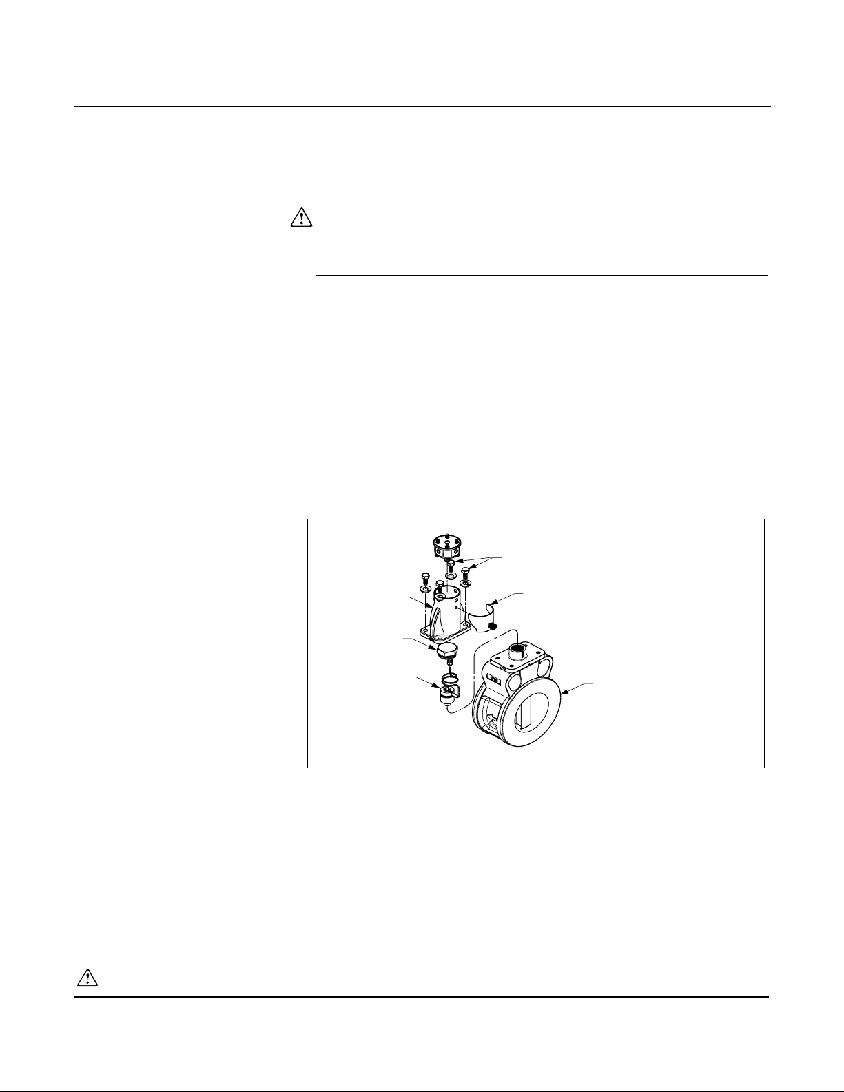
Hardware and Software Maintenance and Troubleshooting
Replacing the Sensor: Remov a ble and Integral Support Tubes
The following procedure applies to flowmeters equipped with a
removable support tube, i.e. all flanged meters and ½- through 4-inch
(DN 15 through 100) wafer meters.
1. De-pressurize the flow line.
NOTE
Sensor cavity could contain line pressure if an abnormal failure has
occurred inside the meter body. De-pressurize flow li ne before removi ng
the sensor nut.
2. Remove the electronics housing (see Replacing the Electronics
Removabl e Support Tube (for1/2- to 4-in. wafer meters and all flanged
meters)
3. Loosen the four support tube anchor bolts with a 7/16-inch open
4. Remove the support tube.
Figure 4-10. Removable Support Tube Assembly
Housing on page 4-13).
• For meters with a removable support tube (1/2- to 4-in. [15 to
100 mm] wafer meters and all flanged meters), follow steps 3-5.
end wrench. See Figure 4-10.
Anchor Bolts
Removable
Support Tube
Sensor Nut
Sensor
Access Cover
Meter Body
5. Proceed to st ep 8.
• For meters with an integral support tube, (6- to 8-in. [100 to
200 mm] wafer meters), follow steps 6-7.
8800-0463A02B
See Safety Messages on page 4-1 for complete w arn i ng i nformation .
4-17
Page 92
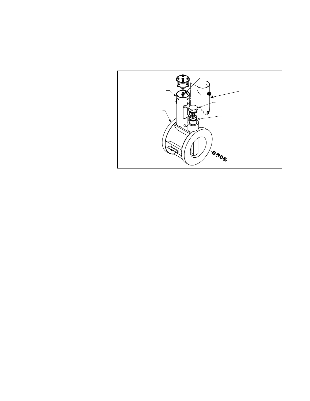
Rosemount Model 8800C Vortex Flowmeter
Integral Support Mount (for 6- to 8-in. wafer meters)
6. Remove access cover. See Figure 4-11.
Figure 4-11. Integral Support Tube Assembly
Sensor Cable
Nut
Support Tube
Sensor Nut
Wafer Meter
Body
Access Cover
Sensor
7. Proceed to st ep 8.
8. Loosen and remove the sensor nut from the sensor cavity with a
1
1
/8-inch open end wrench. (Use a 3/4-inch open end wrench for 3-
and 4-inch [80 and 100 mm] SST wafers.)
9. Lift the sensor fr om the sensor cavity. Be very careful to lift the
sensor straight up. Do not rock, twist, or tilt the sensor during
removal; this will dama ge the engagement diaphragm.
8800-0463A02B
4-18
Page 93
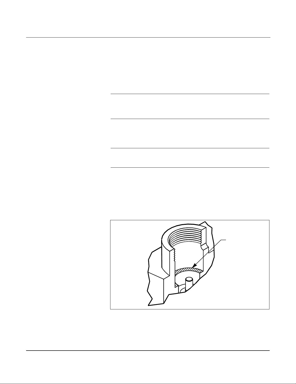
Hardware and Software Maintenance and Troubleshooting
Cleaning the Sealing Surface
Before installing a sensor in the meter body, clean the sealing surface
by completing the following procedure. The metal o-ring on the sensor
is used to seal the sensor cavity in the event that process fluid should
corrode through the meter body and enter th e sensor cavit y. Be sure not
to scratch or otherwise damage any part of the sensor, sensor cavity, or
sensor nut threads. Damage to these parts may require replacement of
the sensor or meter body, or may render the flowmeter dangerous.
NOTE
If you are install ing a senso r that has been used befo re , cl ean t he metal
o-ring on the sensor using the procedure above. If you are installing a
newly purchased sensor, cleaning the o-ring is not necessary.
1. Use a suction or compressed ai r device to remove any loose
particles from the sealing surface and other adjacent areas in the
sensor ca vity.
NOTE
Do not scratch or deform any part of the sensor, sensor cavity, or sensor
nut threads.
2. Carefully brush the sealing surface clean with a soft bristle brush.
3. Moisten a cotton swab with an appropriate cleaning liquid.
4. Wipe the sealing surface. Repeat several times if necessary with a
clean cotton swab until there is minimal dirt residue picked up by
the cotton swab.
Figure 4-12. O-Ring Sealing Surface in Sensor Cavity
Sensor Installation
Sealing Surface
8800-0473A01A
1. Care fu lly plac e sensor ov e r the post in th e sensor ca v ity.
2. Insure that the sensor is centered on the post. See Figure 4-13 for
an example of improper installation and Figure 4-14 for an
example of proper installation.
4-19
Page 94
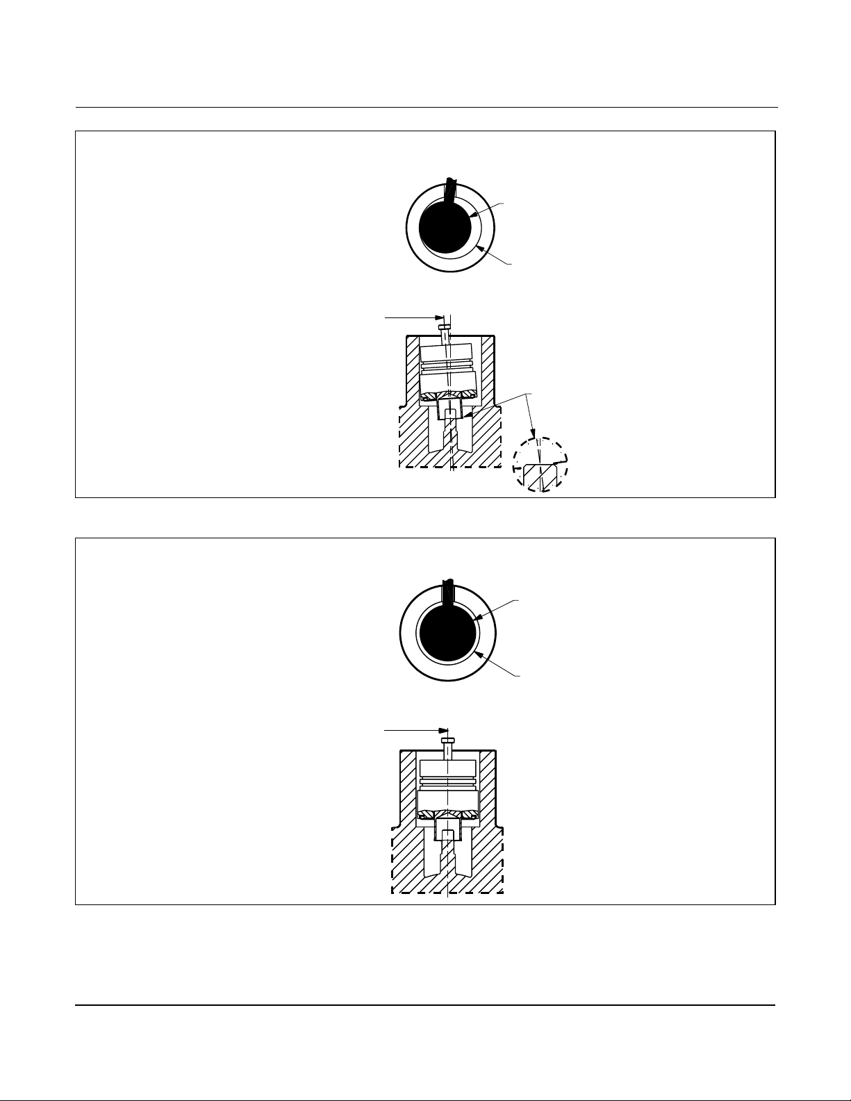
Rosemount Model 8800C Vortex Flowmeter
Figure 4-13. Sensor Installation – Improper Alignment
Improper Alignment
(before seating)
Top View
of Flowmeter
Sensor centerline
is not aligned
with flowmeter
centerline. Dama ge
to sensor will occur.
Figure 4-14. Sensor Installation – Proper Alignment
Top View
of Flowmeter
Sensor
Sensor cavity
in flowmeter
Sensor not
properly aligned
SENSORS-sens05a
Proper Alignment
(befor e se a ting)
Sensor
4-20
Sensor cavity
in flowmeter
Sensor centerline
must be aligned
with flowmeter
centerline
SENSORS-sens05b
Page 95
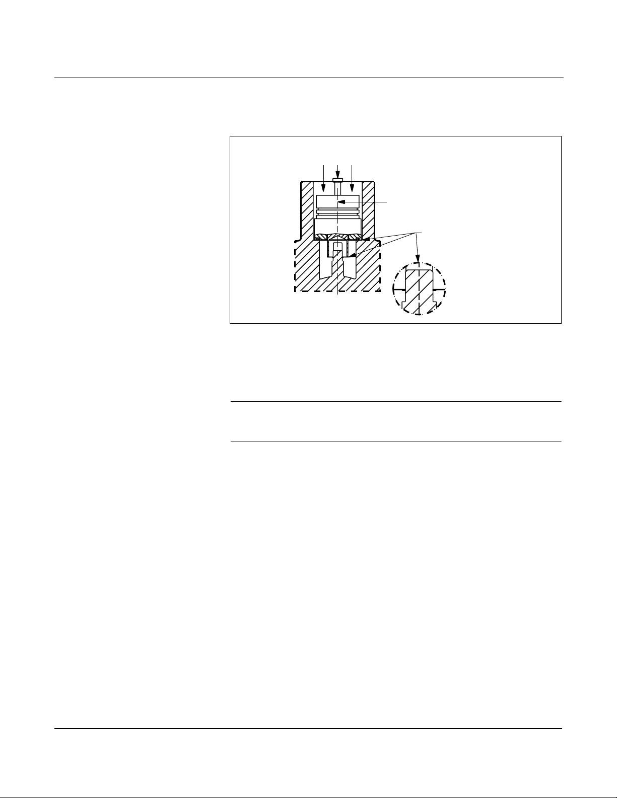
3. Sensor should remain as close to vertical as possible when
Figure 4-15. Sensor Installation – Applying Force
4. Manually push down on the sensor by applying equal pressure for
5. Screw the sensor nut into the sensor cavity. Tighten the nut
Hardware and Software Maintenance and Troubleshooting
applying force to seat. See Figure 4-15.
Pressure
Apply Force
With Hand Until
Sensor is Seated
Sensor centerline must be
aligned with flowmeter
centerline
Sensor properly
seated
engagement on t o t h e p o st.
with a 1
1
/8-inch open end torque wrench to 32 ft-lbs. (Use a 3/4-inch
open end wrench for 3- and 4-inch [80 and 100 mm] SST wafers).
SENSORS-sens05c.
NOTE
The sensor nut must be tightened to 32 ft-lbs. for accurate
flowmeter operati on.
6. Replace the support tube.
7. Tighten the four bolts that anchor the support tube in place
with a
7
/16-inch open end wrench.
8. Install the flowmeter electronics housing. See Install the
Electronics Housing on page 4- 15.
4-21
Page 96

Rosemount Model 8800C Vortex Flowmeter
Remote Electronics Procedure
If the Model 8800C electronics housing is mounted remotely, some
replacement procedures are different than for the flowmeter with
integral electronics. The following procedures are exactly the same:
• Replacing the Field Terminal Block (see page 4-11).
• Replacing the Electronics Boards (se e pa ge4-12).
• Replacing the Sensor (see page 4-15).
To disconnect the coaxial cable from the meter body and electronics
housing, follow the instructions below.
Disconnect the Coaxial Cable at the Meter
1. Remove the access cover on the meter body support tube .
2. Loosen the three housing rotation screws at the base of the
electronics housing with a hex wrench by turning the screws
clockwise (inward) until they will clear the bracket.
3. Loosen and remove the sensor cabl e nut from the union using
5
a
/16-inch open end wrench.
4-22
Page 97
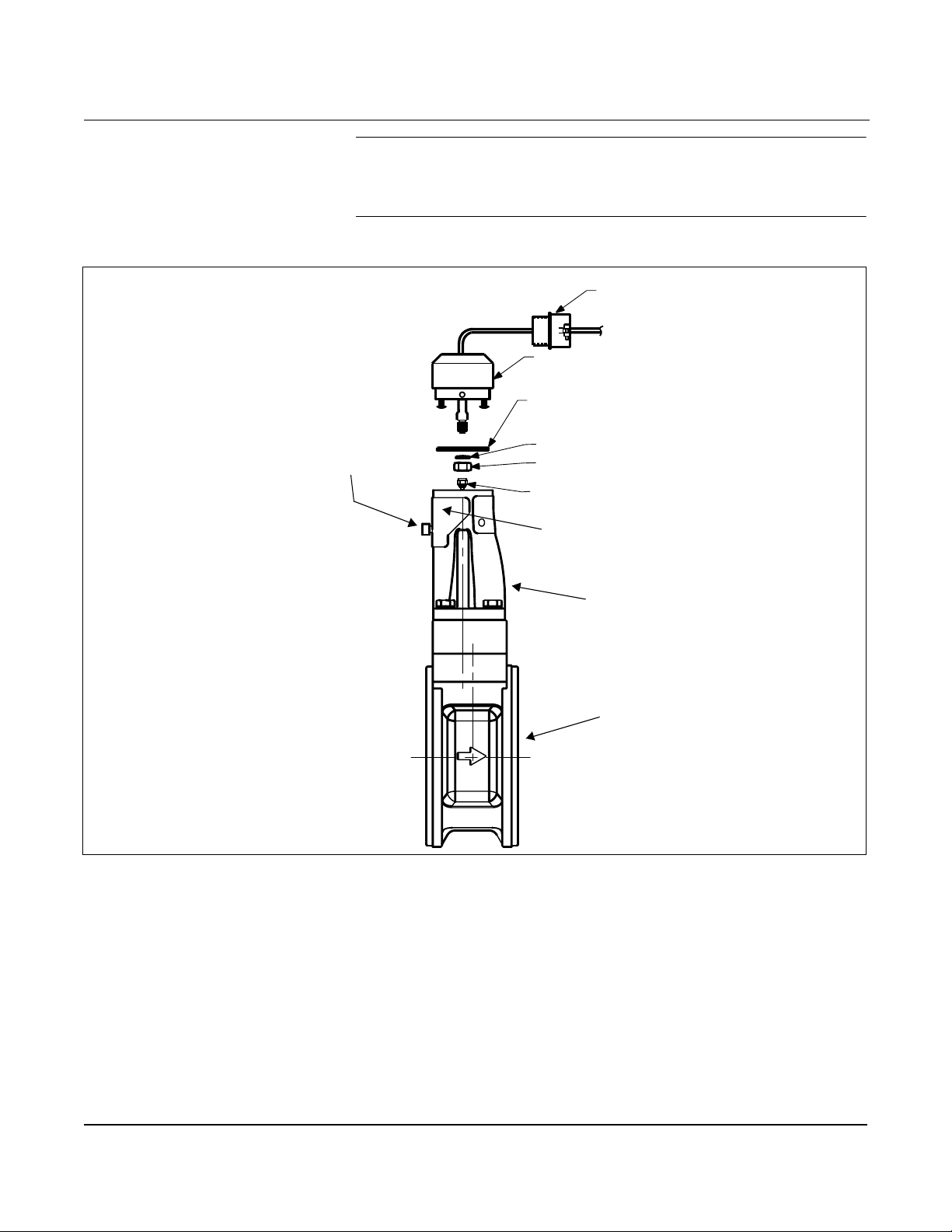
Figure 4-16. Coaxial Cable Connections
Access Cover Screw
Hardware and Software Maintenance and Troubleshooting
NOTE
Do not pull the adaptor more than 1.5 inches (40 mm) from the top of
the support t ube. Damage to the sensor may occur if t he sensor cable is
stressed.
½ NPT Optional Conduit Adapter or
Cable Gland (Supplied by Customer)
Coaxial Cable
Meter Adapter
Union
Washer
Nut
Sensor Connection
Access Cover
Support Tube
Meter Body
8800-0470A02C
4-23
Page 98

Rosemount Model 8800C Vortex Flowmeter
Detach th e M et e r A d a p te r
The above instructions w ill provide access to the meter body. Use the
following steps if it is necessary to remove the coaxial cable:
1. Loosen the two screws that hold the union onto the meter adapter
and pull the union away from the adapter.
2. Loosen and remove the coaxial cable nut from the other end
of the union.
3. Loosen the conduit adapter or cable gland from the
meter adapter.
Attach the Meter Adapter
1. If you are using a conduit adapter or cable gland, slide it over the
plain end of the coaxial cable (the end without a ground wire).
2. Slide the meter adapter over the coaxial cable end.
3. Use a 5/16-inch open end wrench to securely tighten the coaxial
cable nut onto one end of the union.
4. Place the union onto the two screws extending out of the meter
adapter and tighten the two screws.
Connect the Coaxial Cable at the Meter
1. Pull the sensor cable out of the support tube slightly and securely
tighten the sensor cable nut onto the union.
NOTE
Do not stretch the sensor cable over 1.5 inches (40 mm) beyond the top
of the support tube . Damage to the sensor may occur i f the sensor cabl e
is stressed.
2. Place the meter adapter int o the top of the support tube and line
up the screw holes.
3. Use a hex wrench to turn the three adapter screws outward to
engage the support tube.
4. Replace the access co ver on the support tube.
5. Tighten the conduit adapter or cable gland into the
meter adapter.
4-24
Page 99
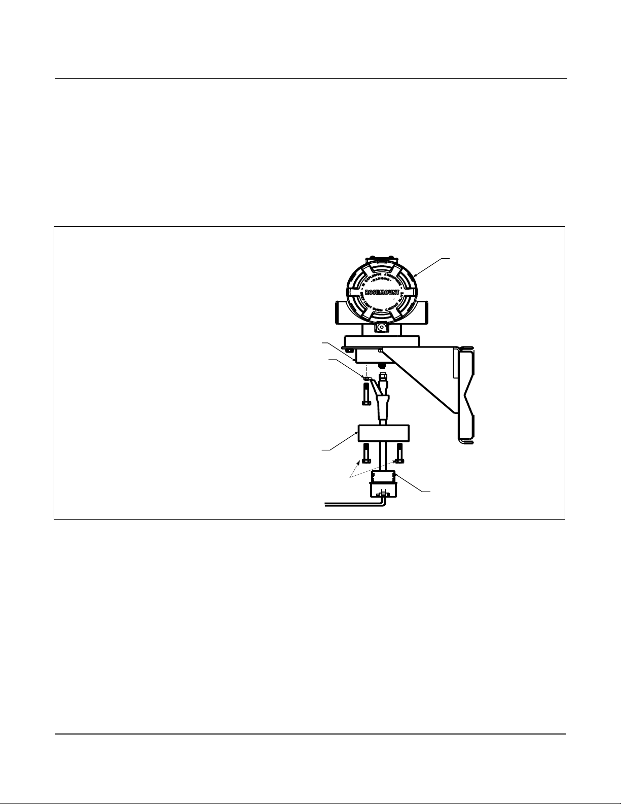
Hardware and Software Maintenance and Troubleshooting
Coaxial Cable at the Electronics Housing
Disconnect the Coaxial Cable from the Elect ronics Housing
1. Loosen the three screws f rom the housing adapter.
2. Remove the adapter from the housing.
3. Loosen and remove the coaxial cable nut from the base of the
Remove the Coaxial Cable
1. Remove the coaxial cable ground wire from the housing adapter.
Figure 4-17. Remote Electronics Exploded View
electr onics hou sing.
Electronics Housing
Housing
Base
Ground
Connection
Housing Adapter
Housing Adapter Screws
Conduit Adapter
2. Loosen the conduit adapter (or cable gland) from the
housing adapter.
Attach the Coaxial Cable
1. Route the coaxial cable through the conduit (if you are
using conduit).
2. Place a conduit adapter over the end of the coaxial cable.
3. Remove the housing adapter from the electronics housing
(if attac h ed ).
4. Slide the housing adapt er over the coaxial cable.
5. Remove one of the four housing base screws.
6. Attach the coaxial cable ground wire to the housing via the
housing base ground screw.
8800-0470B01A
4-25
Page 100

Rosemount Model 8800C Vortex Flowmeter
Connect the Coaxial Cable
1. Attach and secur ely ti ghte n the coaxial cable nut to t he co nnectio n
on the electronics housing.
2. Align the housing adapter with the housing and attach with
three screws.
3. Tighten the conduit adapter to the housing adapter.
Changing the Housing Orientation
The entire electr onics housing may be rotated in 90 degree increments
for easy viewing. Use the following steps to change the housing
orientation:
1. Loosen the screw on the access cover (on the support tube) and
remove the cover.
2. Loosen the three housing rotation set screws at the base of the
electronics housing with a hex wrench by turning the screws
clockwise (inward) until they will clear the support tube.
3. Slow ly pull th e el ectroni cs housin g ou t of the supp o rt tube.
4. Unscrew the sensor ca ble from the housing with a 5/16-inch open
end wren ch.
NOTE
Do not pull the housing more than 1.5 inches (40 mm) from the top of
the support tube until the sensor cable is disconnected. Damage to the
sensor may occur if thi s sensor cable is stressed.
5. Rotate the housing to the desired orientation.
6. Hold it in this orientation while you screw the sensor cable onto
the base of the housing .
NOTE
Do not rotate the housing while the sensor cabl e is atta ched to the base
of the housing . This will stress the cable and may dam a ge the sensor.
4-26
7. Place the electronics housing into the top of the support tube.
8. Use a hex wrench to turn the three housing rotation screws
outward to engage the support tube.
9. Replace the access co ver on the support tube.
10. Tigh te n the scre w o n th e ac cess cov er.
 Loading...