

Page 1
Part Number: 87340-1001, Rev. 0
Release: April 2015
User Manual for TEC2 Display Module
(Model 87340)
User Manual
Page 2
User Manual
Part Number: 87340-1001, Rev. 0
Section 1: Display Module
1.1 Local Display Module
Display Module with Bluetooth® - Model 87340.
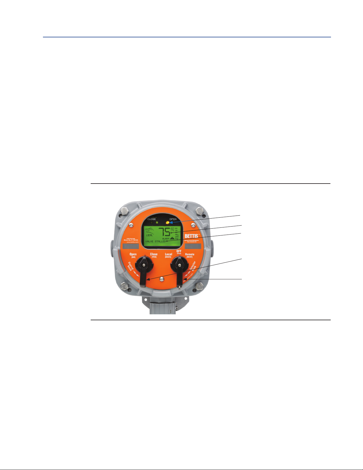
The Local Display module consists of the following as shown in Figure 1:
• Graphics Display
• Message Center
• Control Knob and Selector Knob
• Three LEDs
Figure 1 Local Display Module (LDM)
Display Module
April 2015
1.1.1 Graphics Display and Message Center
The graphics display shows the mode of operation, valve status, position, torque, and
alarm symbols. The message center displays actuator setup selections, data entry
feedback, and alarm messages. When no alarms are active and the valve is not moving
or is not at either limit, the message center will be blank.
1.1.2 Control Knob and Selector Knob
The control knob performs normal Open/Stop/Close function in the local control mode
and YES/NO function in the “MONITOR/SETUP” mode as detailed in Table 1.
LEDs
Graphics Display
Message Center
Control Knob
Selector Knob
Display Module
The NO selection increments the displayed value but does not decrement.
To decrement continuously hold the NO position until the highest value is reached.
The display value will then start at the lowest value and increment from there. If the
control knob is held in the NO position for more than 2 seconds the incrementing rate
will increase from 0.5 seconds per new value to 0.1 seconds per value.
1
Page 3
Display Module
April 2015
Part Number: 87340-1001, Rev. 0
The selector knob performs normal selector switch Local/Stop/Remote function and
alternate Next/Back display function in the “MONITOR/SETUP” mode as detailed
in Table 1.
The NEXT and BACK selections are used strictly for cycling through the SETUP displays
to locate the desired display or to exit the “SETUP” mode.
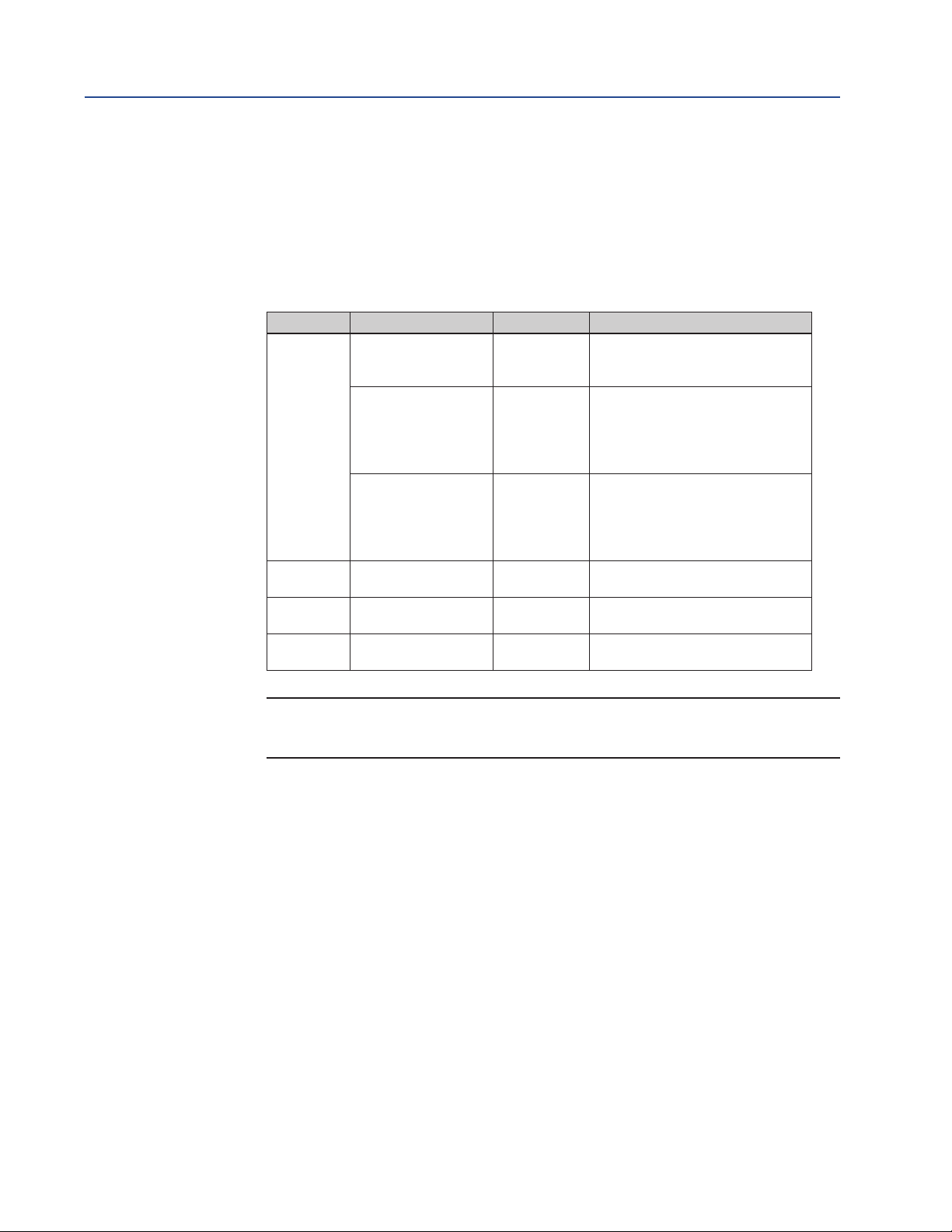
Table 1. LDM Rotating Knobs
Knob Rotation Direction Function Result
User Manual
Spring return to
center
Clockwise
Control
Selector STOP
(CLOSE)
Counterclockwise
(OPEN)
Clockwise
(REMOTE)
Counterclockwise
(LOCAL)
Neutral
Position
YES
NO
Neutral
Position
NEXT Advances to the next display
BACK Returns to the previous display
Completes YES or NO entry cycle.
Exception: when knob is held for
continuous data entry updates.
Accepts the displayed question or
data entry. Advances to the next
display.
Exception: when knob is held for
continuous data entry updates.
Rejects displayed question or data.
Increments to the next data value or
display. Exception: when knob is
held for continuous data entry
updates.
Sets up entry, completes NEXT or
BACK entry cycle. See Note below
NOTE:
If the selector knob remains in either NEXT or BACK position, the display will scroll.
1.1.3 LEDs
There are three LEDs on the LDM:
• Red
• Green
• Yellow
The default function of these LEDs is detailed in Table 2.
1.1.4 Normal Display Function
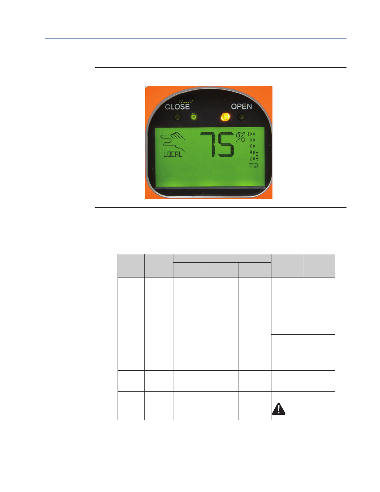
Figure 2 details the display during normal function. The bar graphs, position digits,
icons, and LEDs indicate normal activity, that is, the valve opening, closing, or stopping
in mid-travel. The message center remains blank until alarms are active or the valve is
opening, closing, full open, or full close.
Table 2 details various normal activities and how each is displayed.
2
Display Module
Page 4
User Manual
Part Number: 87340-1001, Rev. 0
Figure 2 Normal Display
Display Module
April 2015
The valve has stopped and is 75% opened. The yellow LED is ON and the message
center is clear.
Table 2. Normal Display Functions
Valve
Activity
Fully
closed
Opening OPENING OFF Blinking OFF
Stopped Cleared ON OFF OFF
Fully
opened
Closing CLOSING OFF OFF Blinking
Alarm
Message
Center
Top Line
FULL
CLOSE
FULL
OPEN
Alarm Type
Displayed
-Bottom
Line
Display Functions (LEDs)
Yellow Red Green
OFF OFF ON 0%
OFF ON OFF 100%
Blinking OFF OFF
Position
Bar Graph
Flashing in
the Open
direction
STOP Icon is Displayed
Shows
relative
position
Flashing in
the Close
direction
Alarm Icon
Percent
Open
"XX%"
Increments
% open
Decrements
Display Module
3
Page 5
Display Module
April 2015
1.2 Remote Display Module (RDM)
Display Module with Bluetooth® - Model 87340
The RDM performs the same functions as the LDM.
NOTE:
If the RDM does not receive communication messages from the Central Control Module (CCM)
within 5 seconds after power is applied, the RDM will display the ashing message “CCM LINK
FAILED” and all three LEDs will blink. This will also occur if communication is lost for 5 seconds
or more.
If RDM 1 or 2 is enabled and not connected, the actuator will be in stop mode and cannot be
operated until RDM is connected or disabled.
Part Number: 87340-1001, Rev. 0
User Manual
1.2.1 RDM Operation with LDM
Two RDMs and an LDM can be connected to one actuator. The operation priority is
detailed in Table 3.
Table 3. RDM and LDM Operation Priority
Mode of Operation LDM, RDM #1, RDM #2 and Selector Switch Position
STOP
LOCAL
REMOTE
At least one module must have the selector switch in the STOP
position.
At least one module must have the selector switch in the LOCAL
position and none have the selector switch in the STOP position.
All modules must have the selector switch in the REMOTE
position.
4
Display Module
Page 6

World Area Confi guration Centers (WACC) offer sales support, service,
inventory and commissioning to our global customers.
Choose the WACC or sales offi ce nearest you:
NORTH & SOUTH AMERICA
19200 Northwest Freeway
Houston TX 77065
USA
T +1 281 477 4100
Av. Hollingsworth
325 Iporanga Sorocaba
SP 18087-105
Brazil
MIDDLE EAST & AFRICA
P. O. Box 17033
Jebel Ali Free Zone
Dubai
T +971 4 811 8100
P. O. Box 10305
Jubail 31961
Saudi Arabia
T +966 3 340 8650
T +55 15 3413 8888
24 Angus Crescent
ASIA PACIFIC
Longmeadow Business Estate East
P.O. Box 6908 Greenstone
No. 9 Gul Road
#01-02 Singapore 629361
T +65 6777 8211
No. 1 Lai Yuan Road
1616 Modderfontein Extension 5
South Africa
T +27 11 451 3700
EUROPE
Wuqing Development Area
Tianjin 301700
P. R. China
T +86 22 8212 3300
Holland Fasor 6
Székesfehérvár 8000
Hungary
T +36 22 53 09 50
Strada Biffi 165
29017 Fiorenzuola d’Arda (PC)
Italy
T +39 0523 944 411
For complete list of sales and manufacturing sites, please visit
www.emerson.com/actuationtechnologieslocations or contact us at
[email protected]
www.emerson.com/bettis
©2018 Emerson. All rights reserved.
The Emerson logo is a trademark and service mark of Emerson Electric Co.
TM
is a mark of one of the Emerson family of companies.
Bettis
All other marks are property of their respective owners.
The contents of this publication are presented for information purposes
only, and while every effort has been made to ensure their accuracy,
they are not to be construed as warranties or guarantees, express or
implied, regarding the products or services described herein or their use
or applicability. All sales are governed by our terms and conditions, which
are available on request. We reserve the right to modify or improve the
designs or specifications of our products at any time without notice.
 Loading...