

Page 1
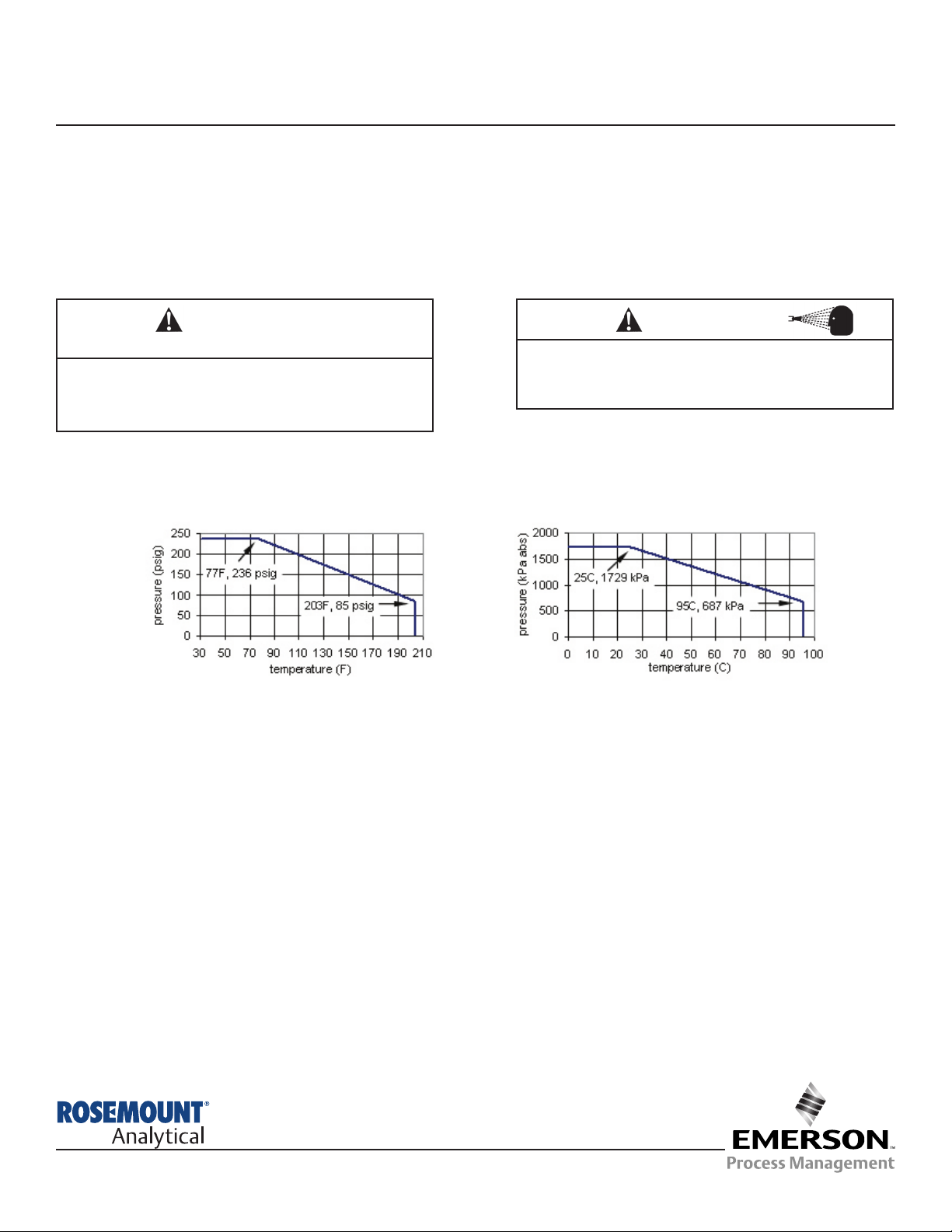
Pressure and Temperature:
Wetted materials: Unfilled PEEK, 316L stainless steel, EP (option 22 only). PEEK meets 21CFR177.2415. EP meets
21CFR177.2600.
Surface finish: 16 microinch (0.4 micron) Ra (except electrode surfaces)
Steam sterilization: tolerates SIP to 284°F (140°C)
Model 410VP
Four-electrode Conductivity Sensor
Instruction Sheet
PN 51A-410VP/rev.D
February 2013
CAUTION
SENSOR/PROCESS APPLICATION COMPATIBILITY
The wetted sensor materials may not be compatible
with process com position and operating conditions.
Application compat ibility is entirely the responsibility
of the user.
INSTALLATION
SENSOR SPECIFICATIONS
The 410VP sensor is available with four process connections: 1½ inch Tri-Clamp1, 2-inch Tri-Clamp, G 1¼, and Varivent N2.
Gaskets and clamps for the Tri-Clamp and Varivent connections must be supplied by the user.
Install the sensor so that the electrodes are completely immersed in the process liquid. Avoid installing the sensor in places
where air bubbles are likely to get trapped or sediment is likely to accumulate on the electrodes. Generally, mounting the
sensor in a vertical pipe run is best. If the sensor must be installed in a horizontal pipe, place the sensor in the 3 o’clock
position. Keep at least 1.0 inch (25 mm) clearance between the end of the sensor and the opposite pipe wall.
To keep response time as fast as possible, do not install the sensor in dead legs or areas where circulation is poor.
1
Tri-Clamp is a registered trademark of Alfa Laval, Inc.
2
Varivent is a registered trademark of Tuchenhagen, GmbH.
WARNING
Before removing the sensor, be absolutely certain
that the process pressure is reduced to 0 psig and
the process temperature is lowered to a safe level!
CAUTION
For additional information, please refer to the Instruction Manuals CD shipped with this
product, or visit our website at www/rosemountanalytical.
Page 2
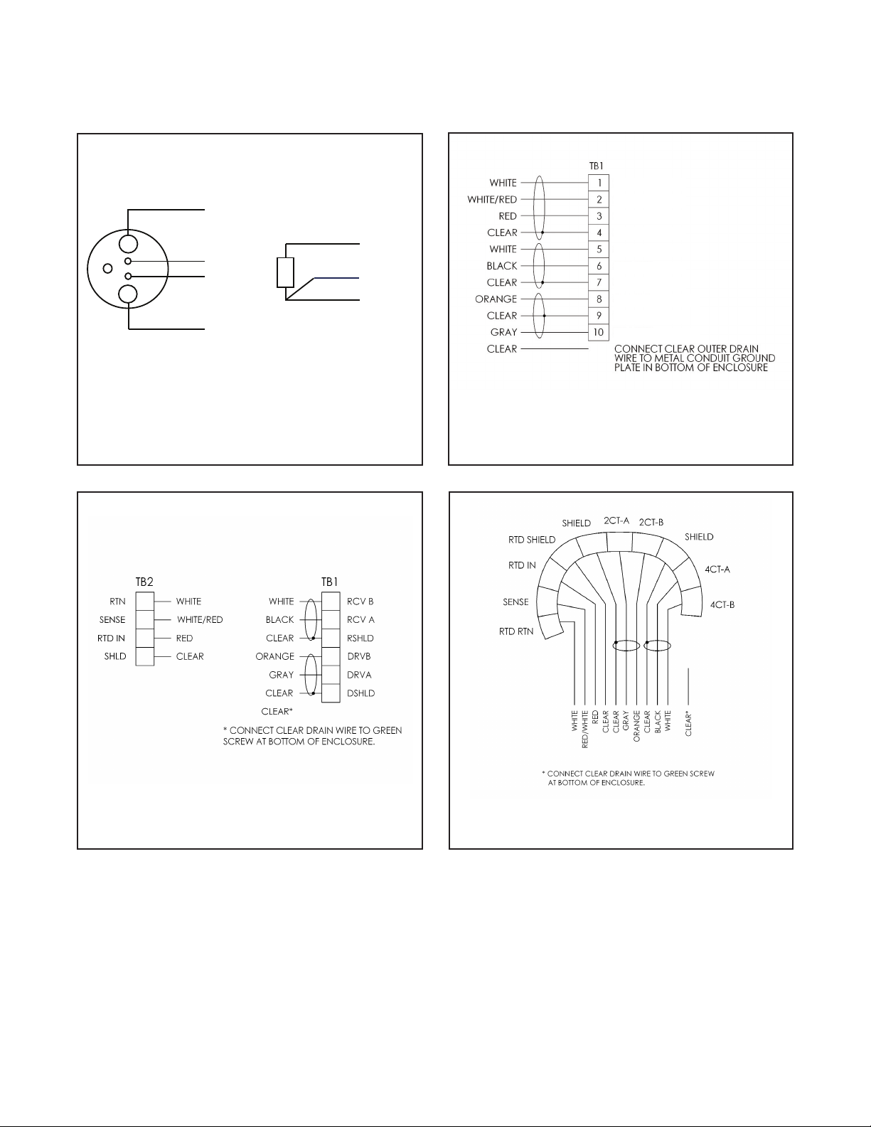
Figure 1. Wire color and functions. Current is
injected through the gray and orange wires. Voltage
is measured across the white and black wires.
Figure 2. Model 1056 and Model 56 wiring.
WIRING
MODEL 410VP WIRING
2
Figure 3.Model 1066 wiring
Figure 4. Model 6081-C wiring
The terminal end of the sensor is keyed to ensure proper mating with the cable receptacle. Once the key has slid
into the mating slot, tighten the connection by turning the knurled ring clockwise.
4CT B
RTD RTN
RTD SENSE
RTD IN
RTD SHLD
4CT A
SHLD 2CT
SHLD 2CT
SEN 2CT B
SEN 2CT A
orange
current
red
RTD
white
black
gray
voltage
voltage
current
white/red
white
RTD in
RTD sense
RTD return
Page 3

3
MODEL 410VP CALIBRATION
The sensor is calibrated at the factory and does not require initial user-calibration. Simply configure the analyzer
to accept a four-electrode sensor and enter the cell constant and calibration factor printed on the label.
After a period of service, the sensor may require calibration. The sensor can be calibrated against a solution
having known conductivity or against a referee meter and sensor. If using a standard solution, choose one
having conductivity greater than 500 uS/cm. Do not use standard solutions having conductivity less than
100 uS/cm. They are susceptible to contamination by atmospheric carbon dioxide, which can alter the
conductivity by a variable amount as great as 1.2 uS/cm (at 25°C). Calibration changes the cell constant
only, not the calibration factor. If you wish to change the calibration factor, consult the factory. For more
information about calibrating contacting conductivity sensors see application sheet ADS 43-024 available
on the Rosemount Analytical website at www.rosemountanalytical.com.
SETUP AND CALIBRATION
TROUBLESHOOTING
PROBLEM PROBABLE CAUSE SOLUTION
Off-scale reading
Wiring is incorrect.
Verify wiring.
RTD is open or shorted.
Check RTD for open connections or
shorts. See Figure 1.
Sensor is not in process stream.
Be sure sensor is completely submerged
in process stream.
Variopol cable is not properly seated. Loosen connector and reseat.
Noisy reading
Sensor is improperly installed in process
stream.
Be sure sensor is completely submerged
in process stream.
Variopol cable is not properly seated. Loosen connector and reseat.
Reading seems wrong (lower
or higher than expected)
Bubbles trapped on sensor.
Be sure sensor is installed so that air
cannot become trapped against it.
Wrong temperature correction algorithm.
Check that temperature correction algorithm is appropriate for the sample. See
the analyzer manual for more information.
Wrong cell constant. Wrong calibration
factor.
Verify that the correct cell constant and
calibration factor have been entered in the
analyzer. See the analyzer manual for
more information.
Bottom of sensor is too close to pipe
wall.
Maintain at least 1.0 in (25 mm) clearance
between bottom of sensor and opposite
pipe wall.
Temperature reading in error
Disconnect red and white RTD wires.
Measure resistance across leads, which
should be about 1100Ω at room
temperature.
Sluggish response
Electrodes are fouled. Clean electrodes.
Sensor is installed in dead area in
process piping
Move sensor to a location more representative of the process liquid.
Page 4

Credit Cards for U.S. Purchases Only.
The right people,
the right answers,
right now.
ON-LINE ORDERING NOW AVAILABLE ON OUR WEB SITE
http://www.rosemountanalytical.com
Specifications subject to change without notice.
8
Emerson Process Management
2400 Barranca Parkway
Irvine, CA 92606 USA
Tel: (949) 757-8500
Fax: (949) 474-7250
http://www.rosemountanalytical.com
© Rosemount Analytical Inc. 2011
 Loading...