


Instruction Manual |
403 and 403VP |
LIQ-MAN-ABR-403-403VP |
February 2015 |
|
|
PURSense
™
Conductivity Sensors
For additional information, please visit our website at www.rosemountanalytical.com.

 CAUTION
SENSOR/PROCESS APPLICATION COMPATIBILITY
The wetted sensor materials may not be compatible with process com position and operating conditions. Application compat ibility is entirely the responsibility of the user.

 WARNING
Before removing the sensor, be absolutely certain that the process pressure is reduced to 0 psig and the process temperature is lowered to a safe level!
Specifications - Sensor
Specifications |
403 and 403VP |
|
|
|
|
Wetted Materials |
titanium, PCTFE, 316 SS, EP |
|
|
|
|
Temperature Range |
32–221 °F (0–105 °C) Sensors tolerate |
|
steam sterilization to 135 °C |
||
|
||
|
|
|
Maximum Pressure |
250 psig (1825 kPa abs) |
|
|
|
NOTE
Elastomers and fluorocarbon resins are compatible with 21CFR177. Elastomers also meet the requirements of USP
Class VI. Stainless steel contains <5 % delta ferrite. All surfaces in have 16 microinch (0.4 micrometer) Ra finish.
Installation
Depending on the option selected, the sensor can be installed in either a 1 ½-inch or 2-inch Tri-Clamp tee. The gasket,
Figure 1. Sensor Orientation |
|
|
Figure 2. Recommended Installation |
|||||||||||||||||||||||||||||
|
|
|
|
|
|
|
|
|
|
|
|
|
|
|
|
|
|
|
|
|
|
|
|
|
|
|
|
|
|
|
|
|
|
|
|
|
|
|
|
|
|
|
|
|
|
|
|
|
|
|
|
|
|
|
|
|
|
|
|
|
|
|
|
|
|
|
|
|
|
|
|
|
|
|
|
|
|
|
|
|
|
|
|
|
|
|
|
|
|
|
|
|
|
|
|
|
|
|
|
|
|
|
|
|
|
|
|
|
|
|
|
|
|
|
|
|
|
|
|
|
|
|
|
|
|
|
|
|
|
|
|
|
|
|
|
|
|
|
|
|
|
|
|
|
|
|
|
|
|
|
|
|
|
|
|
|
|
|
|
|
|
|
|
|
|
|
|
|
|
|
|
|
|
|
|
|
|
|
|
|
|
|
|
|
|
|
|
|
|
|
|
|
|
|
|
|
|
|
|
|
|
|
|
|
|
|
|
|
|
|
|
|
|
|
|
|
|
|
|
|
|
|
|
|
|
|
|
|
|
|
|
|
|
|
|
|
|
|
|
|
|
|
|
|
|
|
|
|
|
|
|
|
|
|
|
|
|
|
|
|
|
|
|
|
|
|
|
|
|
|
|
|
|
|
|
|
|
|
|
|
|
|
|
|
|
|
|
|
|
|
|
|
|
|
|
|
|
|
|
|
|
|
|
|
|
|
|
|
|
|
|
|
|
|
|
|
|
|
|
|
|
|
|
|
|
|
|
|
|
|
|
|
|
|
|
|
|
|
|
|
|
|
|
|
|
|
|
|
|
|
|
|
|
|
|
|
|
|
|
|
|
|
|
|
|
|
|
|
|
|
|
|
|
|
|
|
|
|
|
|
|
|
|
|
|
|
|
|
|
|
|
|
|
|
|
|
|
|
|
|
|
|
|
|
|
|
|
|
|
|
|
|
|
|
|
|
|
|
|
|
|
|
|
|
|
|
|
|
|
|
|
|
|
|
|
|
|
|
|
|
|
|
|
|
|
|
|
|
|
|
|
|
|
|
|
|
|
|
|
|
|
|
|
|
|
|
|
|
|
|
|
|
|
|
|
|
|
|
|
|
|
|
|
|
|
|
|
|
|
|
|
|
|
|
clamp, and tee must be supplied by the user. The electrodes must be completely submerged in the process liquid, i.e., up to the inside surface of the flange.
If the sensor is installed in a side stream with the sample draining to open atmosphere, bubbles may accumulate on the electrodes. Trapped bubbles will cause errors. Normally, as bubbles accumulate the conductivity reading drifts down. To control bubble formation, apply a small amount of back pressure to the sensor.
403 and 403VP |
Instruction Manual |
February 2015 |
LIQ-MAN-ABR-403-403VP |
|
|
Wiring
NOTE
For additional wiring information on this product, including sensor combinations not shown here, please refer to either our online wiring programs or the Manual DVD enclosed with each product.
1056, 1057, 56, 5081, 6081, 54e, and XMT : http://www3.emersonprocess.com/raihome/sp/liquid/wiring/XMT/ 1066 and sensors with SMART preamps: http://www2.emersonprocess.com/en-US/brands/rosemountanalytical/ Liquid/Sensors/Pages/Wiring_Diagram.aspx
1055: http://www3.emersonprocess.com/raihome/sp/liquid/wiring/1055/
Wire Color and Connections in Sensor
COLOR |
FUNCTION |
|
||||
|
|
|
|
|
|
|
Gray |
Connects to outer electrode |
|
||||
|
|
|
|
|
|
|
Clear |
Coaxial shield for gray wire |
|
||||
|
|
|
|
|
|
|
Orange |
Connects to inner electrode |
|
||||
|
|
|
|
|
|
|
Clear |
Coaxial shield for orange wire |
|
||||
|
|
|
|
|
|
|
Red |
RTD |
|
|
|
|
RTD in |
|
|
|
|
|||
|
|
|
|
|
RTD sense |
|
White with red stripe |
|
|
|
|
||
|
|
|
|
|||
White |
|
|
|
|
|
RTD return |
|
|
|
|
|
|
|
|
|
|
|
|
|
|
Clear |
Shield for all RTD lead wires |
|
||||
|
|
|
|
|
|
|
Wiring Diagrams
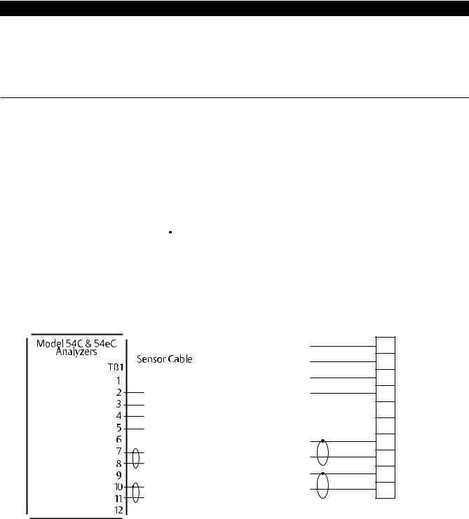
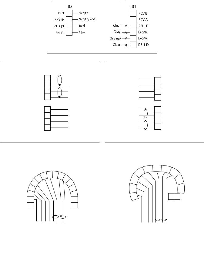
Figure 3. Wiring for 54eC |
|
|
|
|
Figure 4. Wiring for 56 and 1056 |
|
|
|||||
|
|
|
|
|
|
|
|
|
|
|
TB1 |
|
|
|
|
|
|
|
|
|
|
|
White |
1 |
RTD RTN |
|
|
|
|
|
|
|
|
|
|
White/Red |
2 |
RTD SENSE |
|
|
|
GROUND |
|
|
|
|
|
Red |
3 |
RTD IN |
|
|
|
|
|
|
|
|
|
|||||
|
|
|
|
|
|
|
|
|
|
|
||
|
|
|
RTD SHIELD |
|
|
|
|
Clear |
Clear |
4 |
RTD SHLD |
|
|
|
|
RTD RETURN |
|
|
|
|
White |
|
5 |
4CT B |
|
|
|
|
RTD SENSE |
|
|
|
|
White/Red |
|
|||
|
|
|
|
|
|
|
|
|||||
|
|
|
|
|
|
|
|
|
|
|||
|
|
|
|
|
|
|
|
|
|
|
6 |
4CT A |
|
|
|
RTD IN |
|
|
|
|
Red |
|
|||
|
|
|
N/C |
|
|
|
|
|
Clear |
7 |
SHLD 2CT |
|
|
|
|
|
|
|
|
|
|||||
|
|
|
RECEIVE COMMON |
|
|
|
|
Clear |
Orange |
8 |
SEN 2CT B |
|
|
|
|
RECEIVE |
|
|
|
|
Orange |
||||
|
|
|
|
|
|
|
|
|
|
|||
|
|
|
N/C |
|
|
|
|
|
Clear |
9 |
SHLD 2CT |
|
|
|
|
|
|
|
|
|
|||||
|
|
|
|
|
|
|
|
|
Clear |
|
|
|
|
|
|
DRIVE COMMON |
|
|
|
|
Gray |
10 |
SEN 2CT A |
||
|
|
|
|
|
|
|
|
|
Gray |
|||
|
|
|
DRIVE |
|
|
|
|
|
|
|
||
|
|
|
GROUND |
|
|
|
|
|
|
|
|
|
|
|
|
|
|
|
|
|
|
|
|
||
2
Instruction Manual |
|
403 and 403VP |
LIQ-MAN-ABR-403-403VP |
|
February 2015 |
|
|
|
|
|
|
|
Figure 5. Wiring for 1066 |
|
Figure 6. Wiring (Panel) for Xmt-C-10 |
Figure 7. Wiring(Pipe or Wall) for Xmt-C-11 |
||||
|
TB1 |
|
|
TB1 |
|
DRIVE |
8 |
Gray |
Clear |
1 |
RTD SHIELD |
DRIVE COM |
7 |
Clear |
White |
2 |
RTD COM |
RECEIVE |
6 |
Orange |
Red/White |
3 |
RTD SENSE |
RECEIVE COM |
5 |
Clear |
Red |
4 |
RTD IN |
RTD IN |
4 |
Red |
Clear |
5 |
RECEIVE COM |
RTD SENSE |
3 |
Red/White |
Orange |
6 |
RECEIVE |
RTD COM |
2 |
White |
Clear |
7 |
DRIVE COM |
RTD SHIELD |
1 |
Clear |
Gray |
8 |
DRIVE |
Figure 8. Wiring for 5081-C |
|
|
|
Figure 9. Wiring for 6081-C |
|
||
|
MODEL 5081C |
|
|
|
|||
|
TRANSMITTER |
|
SHIELD 2CT-A |
|
|||
|
|
|
DRV |
|
|
2CT-B |
|
|
|
|
|
|
|
|
|
|
RTD |
RCV |
SHLD DRV |
|
RTD SHIELD |
SHIELD |
|
|
COM |
|
|
COM |
DRV |
|
|
RTD SHLD |
7 8 |
9 |
10 |
|
4CT-A |
||
|
RTD IN |
||||||
RTD IN |
6 |
|
|
11 |
|
||
|
|
|
|
|
|||
RTD SENSE |
5 |
|
|
|
12 |
SENSE |
|
4 |
|
|
|
13 |
4CT-B |
||
|
|
|
|
|
|||
RTD COM |
3 |
|
|
|
14 |
RTD RTN |
|
|
|
|
|
|
|
|
|
RTD SHLD |
2 |
|
|
|
15 |
HT/FF (-) |
SMART PWR |
RESERVED |
1 |
|
|
|
16 |
HT/FF (+) |
|
|
|
|
|
||||
CLEAR WHITE WHITE/RED RED CLEAR ORANGE CLEAR GRAY |
WHITE RED/WHITE RED CLEAR CLEAR ORANGE GRAY CLEAR |
SENSOR CABLE |
|
3
 Loading...