

Page 1
Instruction Manual 403 and 403VP
LIQ-MAN-ABR-403-403VP February 2015
PURSense
For additional information, please visit our website at www.rosemountanalytical.com.
CAUTION
SENSOR/PROCESS APPLICATION COMPATIBILITY
The wetted sensor materials may not be compatible with process com position and operating conditions.
Application compat ibility is entirely the responsibility of the user.
WARNING
Before removing the sensor, be absolutely certain that the process pressure is reduced to 0 psig and the process
temperature is lowered to a safe level!
™
Conductivity Sensors
Specifications - Sensor
Specifications 403 and 403VP
Wetted Materials titanium, PCTFE, 316 SS, EP
Temperature Range
Maximum Pressure 250 psig (1825 kPa abs)
NOTE
Elastomers and uorocarbon resins are compatible with 21CFR177. Elastomers also meet the requirements of USP
Class VI. Stainless steel contains <5 % delta ferrite. All surfaces in have 16 microinch (0.4 micrometer) Ra nish.
32–221 °F (0–105 °C) Sensors tolerate
steam sterilization to 135 °C
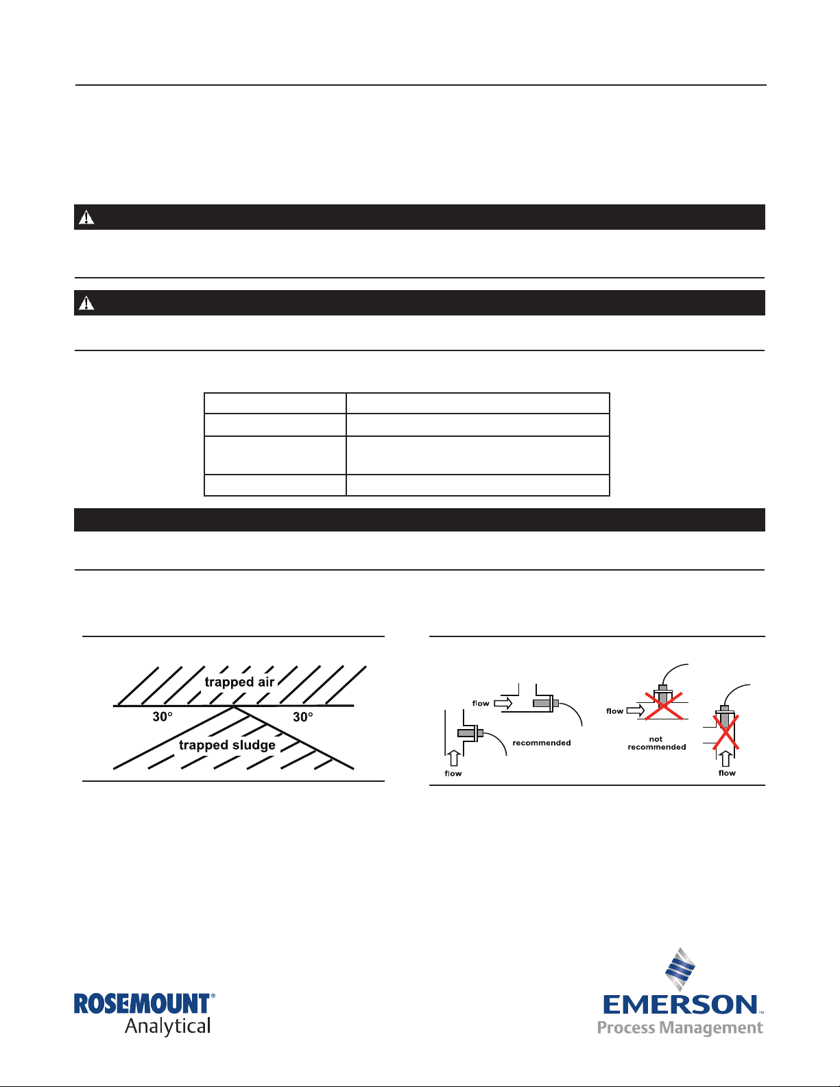
Installation
Depending on the option selected, the sensor can be installed in either a 1 ½-inch or 2-inch Tri-Clamp tee. The gasket,
Figure 1. Sensor Orientation
°
clamp, and tee must be supplied by the user. The electrodes must be completely submerged in the process liquid, i.e., up
to the inside surface of the ange.
If the sensor is installed in a side stream with the sample draining to open atmosphere, bubbles may accumulate on the
electrodes. Trapped bubbles will cause errors. Normally, as bubbles accumulate the conductivity reading drifts down. To
control bubble formation, apply a small amount of back pressure to the sensor.
°
Figure 2. Recommended Installation
Page 2

403 and 403VP Instruction Manual
February 2015 LIQ-MAN-ABR-403-403VP
Wiring
NOTE
For additional wiring information on this product, including sensor combinations not shown here, please refer to either
our online wiring programs or the Manual DVD enclosed with each product.
1056, 1057, 56, 5081, 6081, 54e, and XMT : http://www3.emersonprocess.com/raihome/sp/liquid/wiring/XMT/
1066 and sensors with SMART preamps: http://www2.emersonprocess.com/en-US/brands/rosemountanalytical/
Liquid/Sensors/Pages/Wiring_Diagram.aspx
1055: http://www3.emersonprocess.com/raihome/sp/liquid/wiring/1055/
Wire Color and Connections in Sensor
COLOR FUNCTION
Gray Connects to outer electrode
Clear Coaxial shield for gray wire
Orange Connects to inner electrode
Clear Coaxial shield for orange wire
Red
White with red stripe
RTD
White
Clear Shield for all RTD lead wires
RTD in
RTD sense
RTD return
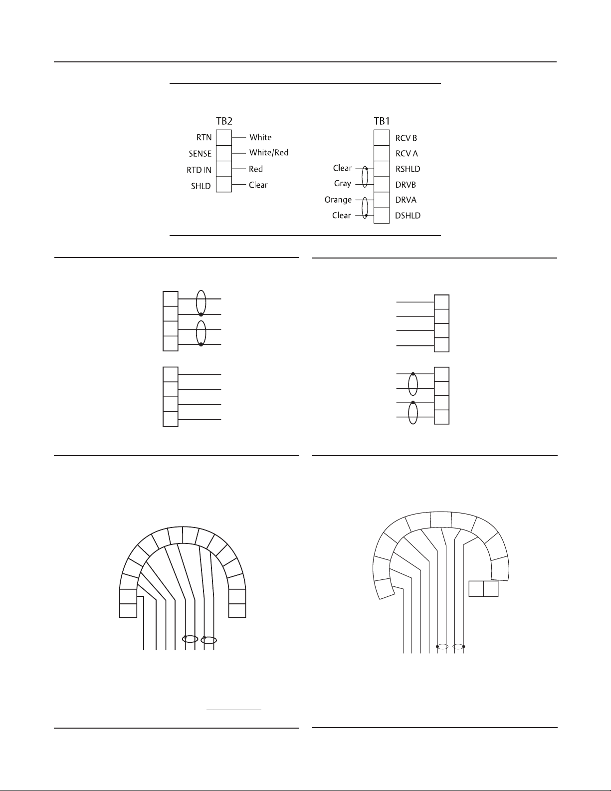
Wiring Diagrams
GROUND
RTD SHIELD
RTD RETURN
RTD SENSE
RTD IN
N/C
RECEIVE COMMON
RECEIVE
N/C
DRIVE COMMON
DRIVE
GROUND
Clear
White
White/Red
Red
Clear
Orange
Clear
Gray
Figure 4. Wiring for 56 and 1056Figure 3. Wiring for 54eC
TB1
White
White/Red
Red
Clear
Clear
Orange
Clear
Gray
1
2
3
4
5
6
7
8
9
10
RTD RTN
RTD SENSE
RTD IN
RTD SHLD
4CT B
4CT A
SHLD 2CT
SEN 2CT B
SHLD 2CT
SEN 2CT A
2
Page 3
Instruction Manual 403 and 403VP
LTR
REVISIONS
DESCRIPTION
DATE
APVD
B
REVISED
12-8-10
J. COVEY
LIQ-MAN-ABR-403-403VP February 2015
Figure 5. Wiring for 1066
Figure 6. Wiring (Panel) for Xmt-C-10
TB1
DRIVE
DRIVE COM
RECEIVE
RECEIVE COM
RTD IN
RTD SENSE
RTD COM
RTD SHIELD
7
6
5
4
3
2
1
Figure 8. Wiring for 5081-C
MODEL 5081C
TRANSMITTER
DRV
RTD SHLD
RTD IN
RTD SENSE
RTD COM
RTD SHLD
RESERVED
RTD
RCV
COM
7
6
5
4
3
2
1
8
SHLD
9
DRV
COM
10
11
Gray8
Clear
Orange
Clear
Red
Red/White
White
Clear
DRV
12
13
14
1516HT/FF (-)
HT/FF (+)
Figure 7. Wiring(Pipe or Wall) for Xmt-C-11
TB1
Clear
White
Red/White
Red
Clear
Orange
Clear
Gray
RTD SHIELD
1
RTD COM
2
RTD SENSE
3
4
RTD IN
5
RECEIVE COM
6
RECEIVE
DRIVE COM
7
DRIVE
8
Figure 9. Wiring for 6081-C
2C T-A
SHIELD
RTD SHIELD
RTD IN
SENSE
RTD RTN
2CT-B
SMART PWR
SHIELD
4C T-A
4CT-B
CLEAR
WHITE
RED
WHITE/RED
CLEAR
CLEAR
ORANGE
SENSOR CABLE
GR AY
WHITE
RED/WHITE
RED
CLEAR
CLEAR
GR AY
CLEAR
ORANGE
3
Page 4

403 and 403VP Instruction Manual
February 2015 LIQ-MAN-ABR-403-403VP
Wiring through a Junction Box
If wiring connections are made through a remote junction box (PN 23550-00), wire point-to-point. Use cable
23747-00 (factory-terminated) or 9200275 (no terminations).
Pin Out Diagram for 400VP
Figure 10. VP pin-out (viewed from connector end of
sensor, looking down)
Cleaning the Sensor
Use a warm detergent solution and a soft brush or pipe cleaner to remove oil and scale. Isopropyl alcohol (rubbing
alcohol) can also be used to remove oily lms. Avoid using strong mineral acids to clean conductivity sensors.
Calibration
PURSense conductivity sensors are calibrated at the factory and do not need calibration when rst placed in service.
Simply enter the cell constant printed on the label into the analyzer.
After a period of service, the sensor may require calibration. The sensor can be calibrated against a solution having
known conductivity or against a referee meter and sensor. If using a standard solution, choose one having conductivity
in the recommended operating for the sensor cell constant. Refer to the analyzer manual or product data sheet
for recommended ranges. Do not use standard solutions having conductivity less than about 100 uS/cm. They are
susceptible to contamination by atmospheric carbon dioxide, which can alter the conductivity by a variable amount as
great as 1.2 uS/cm (at 25°C). Because 0.01/cm sensors must be calibrated in low conductivity solutions, they are best
calibrated against a referee meter and sensor in a closed system.
For more information about calibrating contacting conductivity sensors, refer to application sheet ADS 43-024, available
on the Rosemount Analytical website.
4
Page 5

Instruction Manual 403 and 403VP
LIQ-MAN-ABR-403-403VP February 2015
Troubleshooting
PROBLEM PROBABLE CAUSE SOLUTION
Wiring is wrong. Verify wiring.
RTD is open or shorted. Check RTD for open or short circuits.
See Figure 11.
Off-scale reading
Noisy reading
Reading seems wrong (lower or
higher than expected)
Sluggish response
Sensor is not in process stream. Be sure sensor is completely submerged in
process stream.
Variopol cable is not properly seated. Loosen connector and reseat.
Sensor has failed. Perform isolation checks. See Figure 12.
Sensor is improperly installed in
process stream.
Variopol cable is not properly seated. Loosen connector and reseat.
Bubbles trapped in sensor. Be sure sensor is properly oriented in pipe or
Wrong temperature correction
algorithm.
Wrong cell constant. Verify that the correct cell constant has been
Electrodes are fouled. Clean electrodes.
Sensor is installed in dead area in
piping.
Be sure sensor is completely submerged in
process stream.
ow cell. See Figure 1. Apply back pressure to
ow cell.
Check that temperature correction is
appropriate for the sample. See analyzer
manual for more information.
entered in the analyzer and that the cell
constant is appropriate for the conductivity of
the sample. See analyzer manual.
Move sensor to a location more
representative of the process liquid.
Figure 11. Checking RTD
Disconnect leads and measure resistances shown. The
measured resistance at room temperature should be
close to the value in the table.
red
RTD
red/white
white
Figure 12. Checking Continuity and Leakage
Disconnect electrode leads and measure resistance
and continuity as shown. Sensor must be dry when
checking resistance between electrode leads.
5
Page 6

403 and 403VP Instruction Manual
February 2015 LIQ-MAN-ABR-403-403VP
Notes:
6
Page 7

Instruction Manual 403 and 403VP
LIQ-MAN-ABR-403-403VP February 2015
Notes:
7
Page 8

403 and 403VP Instruction Manual
February 2015 LIQ-MAN-ABR-403-403VP
Rev. P
facebook.com/EmersonRosemountAnalytical
AnalyticExpert.com
twitter.com/RAIhome
youtube.com/user/RosemountAnalytical
Emerson Process Management
2400 Barranca Parkway
Irvine, CA 92606 USA
Tel: (949) 757-8500
Fax: (949) 474-7250
www.RosemountAnalytical.com
Credit Cards for U.S. Purchases Only.
©2015 Rosemount Analytical, Inc. All rights reserved.
The Emerson logo is a trademark and service mark of Emerson Electric Co. Brand name is a mark of one
of the Emerson Process Management family of companies. All other marks are the property of their
respective owners.
The contents of this publication are presented for information purposes only, and while effort has been
made to ensure their accuracy, they are not to be construed as warranties or guarantees, express or
implied, regarding the products or services described herein or their use or applicability. All sales are
governed by our terms and conditions, which are available on request. We reserve the right to modify
or improve the designs or specications of our products at any time without notice.
 Loading...