

Page 1
COMPONENT
SPEC. NO.
584000300
MODEL
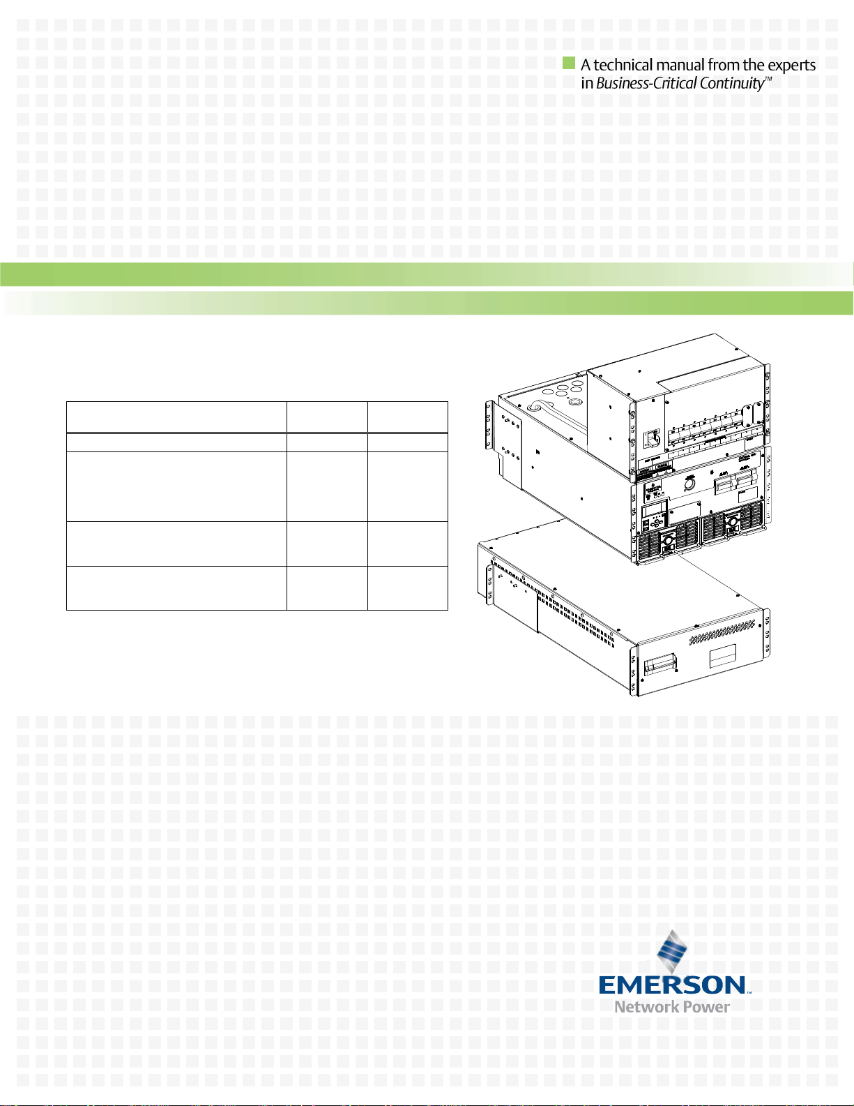
INTEGRATED SYSTEM
LIST R1, R2
4015-X003
LOAD DISTRIBUTION SUB-RACK
HRMG Configuration (w/ row breaker)
NPG Configuration (w/ row breaker)
HRMG Configuration (w/out row breaker)
NPG Configuration (w/out row breaker)
LIST 21
LIST 22
LIST 23
LIST 24
--
POWER AND CONTROL SUB-RACK
HRMG Configuration
NPG Configuration
LIST 11
LIST 12
4015-X003
BATTERY TRAY
HRMG Configuration
NPG Configuration
LIST 91
LIST 92
--
NetSure™ 4015 30kW 400V DC Power System
Installation Instructions
IM584000300 (Issue AB, April 3, 2013)
Page 2

Business-Critical Continuity™, Emerson Network Power, and the Emerson Network
Power logo are trademarks and service marks of Emerson Electric Co.
NetSure™, NetSpan™, NetReach™, NetXtend™, and NetPerform™
are trademarks of Emerson Network Power, Energy Systems, North America, Inc.
All other trademarks are the property of their respective owners.
The products covered by this instruction manual are manufactured and/or
sold by Emerson Network Power, Energy Systems, North America, Inc.
The information contained in this document is subject to change without notice and may not be
suitable for all applications. While every precaution has been taken to ensure the accuracy and
completeness of this document, Emerson Network Power, Energy Systems, North America, Inc.
assumes no responsibility and disclaims all liability for damages resulting from use of this information
or for any errors or omissions. Refer to other local practices or building codes as applicable for the correct
methods, tools, and materials to be used in performing procedures not specifically described in this document.
This document is the property of Emerson Network Power, Energy Systems, North America, Inc.
and contains confidential and proprietary information owned by Emerson Network Power, Energy
Systems, North America, Inc. Any copying, use or disclosure of it without the written permission
of Emerson Network Power, Energy Systems, North America, Inc. is strictly prohibited.
Copyright © 2013, Emerson Network Power, Energy Systems, North America, Inc.
All rights reserved throughout the world.
Page 3

Installation Instructions IM584000300
Spec. No. 584000300 (Model 4015-X003) Issue AB, April 3, 2013
TABLE OF CONTENTS
CONTENTS PAGE
IMPORTANT SAFETY INSTRUCTIONS .................................................................................. iii
General Safety .................................................................................................................................................... iii
Voltages .............................................................................................................................................................. iii
Battery (if equipped) ............................................................................................................................................ iv
Personal Protective Equipment (PPE) ................................................................................................................. v
Maintenance and Servicing Procedures ............................................................................................................. vi
Circuit Card Handling .......................................................................................................................................... vi
STATIC WARNING .................................................................................................................. vii
CHAPTER 1. GENERAL INFORMATION AND INSTALLATION ACCEPTANCE
CHECKLIST ............................................................................................................................... 1
Customer Documentation Package ..................................................................................................................... 1
System Packaging ............................................................................................................................................... 1
Power and Control Sub-Rack (List 11, 12) .................................................................................................... 2
DC Load Distribution Sub-Rack (List 21, 22, 23, 24) .................................................................................... 3
Battery Tray (List 91, 92) ............................................................................................................................... 4
Recommended Tools and Test Equipment .......................................................................................................... 5
Installation Acceptance Checklist ........................................................................................................................ 6
General .......................................................................................................................................................... 6
Checklist –Factory Integrated System (List R1, R2) ..................................................................................... 6
Checklist – Customer Integrated System (ship loose) .................................................................................. 7
CHAPTER 2. INSTALLING THE SYSTEM ................................................................................ 8
General Requirements ......................................................................................................................................... 8
Inspecting the Equipment and Storing for Delayed Installations ......................................................................... 9
Inspecting the Equipment .............................................................................................................................. 9
Storing for Delayed Installation ...................................................................................................................... 9
Securing the IT Rack to the Floor ........................................................................................................................ 9
Factory Integrated Systems (List R1, R2) ..................................................................................................... 9
Installing Individual Sub-Racks into Cutomer Provided IT Rack (not applicable with List R1, R2) ................... 10
Customer Supplied IT Rack Guidelines ...................................................................................................... 10
Installing the Sub-Racks .............................................................................................................................. 10
Electrically Interconnecting the Sub-Rack(s) ............................................................................................... 12
CHAPTER 3. MAKING ELECTRICAL CONNECTIONS .......................................................... 13
Important Safety Instructions ............................................................................................................................. 13
Wiring Considerations ........................................................................................................................................ 13
Torque ................................................................................................................................................................ 13
Output Ground Configurations ........................................................................................................................... 13
Cable Routing .................................................................................................................................................... 13
When System is Furnished in a Factory Provided IT Rack (List R1, R2) .................................................... 13
When System Components are Furnished Loose to be Installed in a Customer Furnished IT Rack ......... 15
Table of Contents Page i
This document is property of Emerson Network Power, Energy Systems, North America, Inc. and contains confidential and proprietary information owned by Emerson Network Power, Energy
Systems, North America, Inc. Any copying, use, or disclosure of it without the written permission of Emerson Network Power, Energy Systems, North America, Inc. is strictly prohibited.
Page 4

IM584000300 Installation Instructions
Issue AB, April 3, 2013 Spec. No. 584000300 (Model 4015-X003)
Tasks to Be performed for Customer Integrated Systems ................................................................................. 17
Grounding .................................................................................................................................................... 17
Sub-Racks Electrical Interconnections ........................................................................................................ 21
Tasks to Be Perform for All Installations ............................................................................................................ 25
Grounding .................................................................................................................................................... 25
AC Input Power Connections ...................................................................................................................... 28
DC Load Distribution Electrical Connections to List 21-24 DC Load Distribution Sub-Rack(s) (if
furnished) ..................................................................................................................................................... 29
Installing Battery Sub-Trays in List 91 and 92 Battery Tray(s) (if furnished) ............................................... 31
External Battery Connections (if required) .................................................................................................. 33
IB2 (ACU+ Controller Interface Board) Connections (if required) ............................................................... 35
ACU+ Controller Ethernet Connection (if required) ..................................................................................... 36
Power and Control Sub-Rack Bulk Output Connections (if required) ......................................................... 40
CHAPTER 4. INSTALLING THE RECTIFIER MODULE ......................................................... 41
CHAPTER 5. INITIALLY STARTING THE SYSTEM ............................................................... 42
Initial Startup Preparation ................................................................................................................................... 42
Initially Starting the System ................................................................................................................................ 43
ACU+ Controller Initialization ............................................................................................................................. 44
Verifying the Configuration File .......................................................................................................................... 46
Changing Battery Capacity Rating in the ACU+ ................................................................................................ 46
Checking Basic System Settings ....................................................................................................................... 47
Configuring the ACU+ Identification of Rectifiers ............................................................................................... 49
Checking the System Shutdown Circuit ............................................................................................................. 50
Checking System Status .................................................................................................................................... 50
Final Steps ......................................................................................................................................................... 51
Reference Documents ....................................................................................................................................... 51
REVISION RECORD ................................ ................................ ................................ ................ 52
Page ii Table of Contents
This document is property of Emerson Network Power, Energy Systems, North America, Inc. and contains confidential and proprietary information owned by Emerson Network Power, Energy
Systems, North America, Inc. Any copying, use, or disclosure of it without the written permission of Emerson Network Power, Energy Systems, North America, Inc. is strictly prohibited.
Page 5
Installation Instructions IM584000300
Spec. No. 584000300 (Model 4015-X003) Issue AB, April 3, 2013
IMPORTANT SAFETY INSTRUCTIONS
GENERAL SAFETY
DANGER! YOU MUST FOLLOW APPROVED SAFETY PROCEDURES.
Performing the following procedures may expose you to hazards. These procedures
should be performed by qualified technicians familiar with the hazards associated with
this type of equipment. These hazards may include shock, energy, and/or burns. To
avoid these hazards:
a) The tasks should be performed in the order indicated.
b) Remove watches, rings, and other metal objects.
c) Prior to contacting any uninsulated surface or termination, use a voltmeter to
verify that no voltage or the expected voltage is present.
d) Wear eye protection, and use recommended tools.
e) Use double insulated tools appropriately rated for the work to be performed.
f) Do not work on an energized system without full arc flash and PPE protection.
DANGER! All power and control wiring should be installed by a qualified electrician.
All power and control wiring must comply with the National Electrical Code (NEC) and
applicable local codes. For operation in countries where the NEC is not recognized,
follow applicable codes.
CAUTION! Performing maintenance and/or troubleshooting procedures may interrupt
power to the loads, if battery reserve is not sufficient or present.
VOLTAGES
AC Input Voltages
DANGER! This system operates from AC voltage capable of producing fatal electrical
shock. AC input power must be completely disconnected from the branch circuits
wiring used to provide power to the system before any AC electrical connections are
made. Follow local lockout/tagout procedures to ensure upstream branch circuit
breakers remain de-energized during installation. DO NOT apply AC power to the
system until all electrical connections have been completed and checked.
DC Input/Output Voltages
DANGER! This system produces DC power and may have a battery source connected
to it. The DC voltage IS hazardously high and the rectifiers and/or battery can deliver
large amounts of current. Exercise extreme caution not to inadvertently contact or
have any tool inadvertently contact an output terminal or battery terminal or exposed
wire connected to an output terminal or battery terminal. NEVER allow a metal object,
such as a tool, to contact more than one termination at a time, or to simultaneously
contact a termination and a grounded object. Even a momentary short circuit can
cause explosion and injury. Remove watches, rings, and other metal objects before
connecting battery leads.
Follow local lockout/tagout procedures to ensure DC branch circuit breakers remain
de-energized during installation at loads, as required.
Extreme caution is required when performing maintenance. Be constantly aware that
this system contains high DC as well as AC voltages.
The maximum output voltage is 400V DC and is potentially lethal.
Check for voltage with both AC and DC voltmeters prior to making contact.
Important Safety Instructions Page iii
This document is property of Emerson Network Power, Energy Systems, North America, Inc. and contains confidential and proprietary information owned by Emerson Network Power, Energy
Systems, North America, Inc. Any copying, use, or disclosure of it without the written permission of Emerson Network Power, Energy Systems, North America, Inc. is strictly prohibited.
Page 6
IM584000300 Installation Instructions
Issue AB, April 3, 2013 Spec. No. 584000300 (Model 4015-X003)
BATTERY (IF EQUIPPED)
DANGER! When connected together, the battery terminal voltage is 400V DC and is
potentially lethal. Battery strings should be isolated from the power system before
servicing.
WARNING! Correct polarity must be observed when connecting battery leads.
WARNING! Special safety precautions are required for procedures involving handling,
installing, and servicing batteries. Observe all battery safety precautions in this
manual and in the battery instruction manual. These precautions should be followed
implicitly at all times.
WARNING! A battery can present a risk of electrical shock and high short circuit
current. Servicing of batteries should be performed or supervised only by properly
trained and qualified personnel knowledgeable about batteries and the required
precautions.
The following precautions should be observed when working on batteries:
Remove watches, rings, and other metal objects.
Eye protection should be worn to prevent injury from accidental electrical arcs.
Use certified and well maintained insulated tools. Use double insulated tools
appropriately rated for the work to be performed. Ensure that wrenches with more
than one working end have only one end exposed.
Do not lay tools or metal parts on top of batteries.
Disconnect charging source prior to connecting or disconnecting battery
terminals.
Risk of explosion if battery is replaced with an incorrect type or if polarity is
reversed. When replacing batteries, replace with the same manufacturer and type,
or equivalent. See your local Emerson representative for a list of approved
batteries.
Dispose of used batteries according to the instructions provided with the batteries.
Do not dispose of batteries in a fire. They may explode.
ALWAYS FOLLOW THE BATTERY MANUFACTURER'S RECOMMENDATIONS AND
SAFETY INSTRUCTIONS.
In addition to the hazard of electric shock, gas produced by batteries can be explosive
and sulfuric acid can cause severe burns. Do not open or mutilate batteries. Released
electrolyte is harmful to the skin and eyes, and is toxic. If electrolyte comes into
contact with skin, the affected area should be washed immediately with large amounts
of water.
Page iv Important Safety Instructions
This document is property of Emerson Network Power, Energy Systems, North America, Inc. and contains confidential and proprietary information owned by Emerson Network Power, Energy
Systems, North America, Inc. Any copying, use, or disclosure of it without the written permission of Emerson Network Power, Energy Systems, North America, Inc. is strictly prohibited.
Page 7
Installation Instructions IM584000300
Spec. No. 584000300 (Model 4015-X003) Issue AB, April 3, 2013
DANGER! THIS EQUIPMENT MAY BE USED IN CONJUNCTION WITH LEAD-ACID
BATTERIES. WORKING NEAR LEAD-ACID BATTERIES IS DANGEROUS!
Batteries contain sulfuric acid.
Batteries generate explosive gases during normal operation. Systems containing
batteries should never be installed in an airtight room or space. Only install in a
ventilated environment.
Batteries are an energy source that can produce high amounts of electrical
current.
FOR THESE REASONS, IT IS OF CRITICAL IMPORTANCE THAT YOU READ THESE
INSTRUCTIONS AND FOLLOW THEM EXACTLY.
WHEN WORKING WITH LEAD-ACID BATTERIES:
Wear complete protection for eyes, face, hands, and clothing. Examples are safety
goggles or face shield, a rubber apron and gloves.
If battery acid enters your eye, immediately flush your eye with running cold water
for at least 15 minutes. Get medical attention immediately.
If battery acid contacts skin or clothing, wash immediately with soap and water.
PERSONAL PROTECTIVE EQUIPMENT (PPE)
DANGER! ARC FLASH AND SHOCK HAZARD.
When working on this equipment appropriate PPE and tools required. An appropriate
flash protection boundary analysis should be done determine the “hazard/risk”
category, and to select proper PPE. Notice that PPE is applicable for both AC and DC
voltages.
This product is intended only for installation in a Restricted Access Location.
Only authorized and properly trained personnel should be allowed to install, inspect,
operate, or maintain the rack/equipment.
Do not work on LIVE parts. If required to work or operate live parts, obtain appropriate
Energized Work Permits as required by the local authority, per NFPA 70E “Standard for
Electrical Safety in the Workplace”.
Important Safety Instructions Page v
This document is property of Emerson Network Power, Energy Systems, North America, Inc. and contains confidential and proprietary information owned by Emerson Network Power, Energy
Systems, North America, Inc. Any copying, use, or disclosure of it without the written permission of Emerson Network Power, Energy Systems, North America, Inc. is strictly prohibited.
Page 8
IM584000300 Installation Instructions
Issue AB, April 3, 2013 Spec. No. 584000300 (Model 4015-X003)
MAINTENANCE AND SERVICING PROCEDURES
General
WARNING! All equipment maintenance and servicing procedures involve internal
access and should be carried out only by trained personnel on a de-energized system.
Extreme caution is required when performing maintenance and servicing procedures.
Be constantly aware that this system contains high DC as well as AC voltages. Check
for voltage with both AC and DC voltmeters prior to making contact.
Special safety precautions are required for procedures involving maintenance of this
system and the batteries. Observe all safety precautions in this manual and in the
battery instruction manual before as well as during performance of all maintenance
procedures. Observe all battery safety precautions before working on or near the
batteries. Service personnel and test equipment should be standing on rubber mats.
Service personnel should wear insulating shoes for isolation from direct contact with
the floor (earth ground).
This equipment contains several circuits that are energized with dangerous voltage.
Only test equipment designed for troubleshooting should be used. This is particularly
true for oscilloscopes. Always check with an AC and DC voltmeter to ensure safety
before making contact or using tools. Even when the power is turned OFF,
dangerously high electric charges may exist within the system.
Never work alone, even if all power is removed from the equipment. A second person
should be standing by to assist and summon help in case an accident should occur.
Dual Hazardous Input Power Sources
WARNING! The system may be powered from dual hazardous input power sources
simultaneously: Commercial AC and Battery DC. Disconnect both sources of power
before servicing.
CIRCUIT CARD HANDLING
WARNING! Installation or removal of the circuit cards requires careful handling.
Before handling any circuit card, read and follow the instructions contained on the
Static Warning Page.
Page vi Important Safety Instructions
This document is property of Emerson Network Power, Energy Systems, North America, Inc. and contains confidential and proprietary information owned by Emerson Network Power, Energy
Systems, North America, Inc. Any copying, use, or disclosure of it without the written permission of Emerson Network Power, Energy Systems, North America, Inc. is strictly prohibited.
Page 9

Installation Instructions IM584000300
Spec. No. 584000300 (Model 4015-X003) Issue AB, April 3, 2013
STATIC WARNING
The printed circuit cards used in this equipment contain static sensitive components. The
warnings listed below must be observed to prevent damage to these components. Disregarding
any of these warnings may result in personal injury or damage to the equipment.
1. Strictly adhere to the procedures provided in this document.
2. Before touching any static sensitive component or printed circuit card containing such a
component, discharge all static electricity from yourself by wearing a wrist strap grounded
through a one megohm resistor. Some wrist straps, such as Emerson Network Power Part
Number 631810600, have a built-in one megohm resistor; no external resistor is necessary.
Read and follow wrist strap manufacturer’s instructions outlining use of a specific wrist strap.
3. Do not touch the traces or components on a printed circuit card containing static sensitive
components. Handle the printed circuit card only by the edges that do not have connector
pads.
4. After removing a printed circuit card containing a static sensitive component, place the
printed circuit card only on conductive or anti-static material such as conductive foam,
conductive plastic, or aluminum foil. Do not use ordinary Styrofoam or ordinary plastic.
5. Store and ship static sensitive devices or printed circuit cards containing such components
only in static shielding containers.
6. If necessary to repair a printed circuit card containing a static sensitive component, wear an
appropriately grounded wrist strap, work on a conductive surface, use a grounded soldering
iron, and use grounded test equipment.
Static Warning Page vii
This document is property of Emerson Network Power, Energy Systems, North America, Inc. and contains confidential and proprietary information owned by Emerson Network Power, Energy
Systems, North America, Inc. Any copying, use, or disclosure of it without the written permission of Emerson Network Power, Energy Systems, North America, Inc. is strictly prohibited.
Page 10

IM584000300 Installation Instructions
Issue AB, April 3, 2013 Spec. No. 584000300 (Model 4015-X003)
This Page Left Intentionally Blank
Page viii Static Warning
This document is property of Emerson Network Power, Energy Systems, North America, Inc. and contains confidential and proprietary information owned by Emerson Network Power, Energy
Systems, North America, Inc. Any copying, use, or disclosure of it without the written permission of Emerson Network Power, Energy Systems, North America, Inc. is strictly prohibited.
Page 11

Installation Instructions IM584000300
Spec. No. 584000300 (Model 4015-X003) Issue AB, April 3, 2013
CHAPTER 1. GENERAL INFORMATION AND INSTALLATION ACCEPTANCE CHECKLIST
CUSTOMER DOCUMENTATION PACKAGE
This document (IM584000300) provides Installation Instructions for NetSure™ Power
System Model 4015-X003, Spec. No. 584000300, and the individual components (Spec.
Nos. listed on the front cover of this document) comprising the system.
The complete Customer Documentation Package consists of…
Bound System Installation Manual
Power System Installation Instructions: IM584000300
Bound System Operation Manual
Power System Operation Instructions: UM584000300
Rectifier Instructions: UM1R40015000e
Power System “System Application Guide”: SAG584000300
Bound ACU+ Controller Operation Manual
ACU+ Controller Operation Instructions: UM1M820NNB-1
USB Drive with All Customer Documentation
Power System Installation Instructions: IM584000300
Power System Operation Instructions: UM584000300
Rectifier Instructions: UM1R40015000e
Power System “System Application Guide”: SAG584000300
ACU+ Controller Operation Instructions: UM1M820NNB-1
Also provided on the USB drive is an ACU+ configuration drawing and the ACU+
configuration files loaded into the ACU+ as shipped.
SYSTEM PACKAGING
The following describes how the system components and hardware are packaged for
shipment, and provides a means of identifying the components and hardware described
in these instructions.
Note: Not all parts may be included in every order.
Chapter 1. General Information and Installation Acceptance Checklist Page 1
This document is property of Emerson Network Power, Energy Systems, North America, Inc. and contains confidential and proprietary information owned by Emerson Network Power, Energy
Systems, North America, Inc. Any copying, use, or disclosure of it without the written permission of Emerson Network Power, Energy Systems, North America, Inc. is strictly prohibited.
Page 12

IM584000300 Installation Instructions
Item
Part Number
Qty.
Power and Control Sub-Rack
553199 (List 11)
554097 (List 12)
1
Rear Mounting Brackets (Sub-Rack)
553313 and 554423
1, each
Screws to Mount Rear Mounting
Brackets to Sub-Rack (10-32 x 1/2”)
221671400
6
Cage Nuts
(Sub-Rack Data Rack Mounting)
P88577
20
Sub-Rack Mounting Screws
for Use with Cage Nuts
(Sub-Rack Data Rack Mounting)
P94896
20
Snap Bushing, 1.093
244823100
5
Snap Bushing, 1.75
244823800
1
Hole Plug, 1.375
144152
1
KEPS Nuts (10-32)
(AC Ground)
104564
4
KEPS Nuts (1/4-20)
(DC Load and Battery)
116638
40
USB Flash Drive (Config File)
144345
1
Cabinet Grounding Jumper
554932
1
Flat Washer, 1/4”
(Data Rack Ground Bar)
214110100
40
Lock Washer, 1/4”
(Data Rack Ground Bar)
215111100
40
Screw, 1/4-20 x 3/4”
(Data Rack Ground Bar)
227640400
40
Screw, 6-32 x 3/8”
(Spares for Rear Cover)
233362700
4
Item
Part Number
Qty.
Rectifier
1R40015000e
1 or 2
Item
Part Number
Qty.
Temperature Probe, 12 Feet (4m)
04118246 and 04118247
1, each
Temperature Probe, 33 Feet (10m)
04118246 and 04116740
1, each
Issue AB, April 3, 2013 Spec. No. 584000300 (Model 4015-X003)
Power and Control Sub-Rack (List 11, 12)
General
Page 2 Chapter 1. General Information and Installation Acceptance Checklist
This document is property of Emerson Network Power, Energy Systems, North America, Inc. and contains confidential and proprietary information owned by Emerson Network Power, Energy
Systems, North America, Inc. Any copying, use, or disclosure of it without the written permission of Emerson Network Power, Energy Systems, North America, Inc. is strictly prohibited.
Rectifiers
Temperature Probes (List 98, 99)
Page 13

Installation Instructions IM584000300
Item
Part Number
Qty.
DC Load Distribution Sub-Rack
553221 (List 21)
553663 (List 22)
553349 (List 23)
554061 (List 24)
1
Cage Nuts
(Sub-Rack Data Rack Mounting)
P88577
8
Sub-Rack Mounting Screws
for Use with Cage Nuts
(Sub-Rack Data Rack Mounting)
P94896
8
KEPS Nut, 1/4-20 (Ground)
116638
1
Cabinet Grounding Jumper
554931
1
Flat Washer, 1/4”
(Data Rack Ground Bar)
214110100
3
Lock Washer, 1/4”
(Data Rack Ground Bar)
215111100
3
Screw, 1/4-20 x 3/4”
(Data Rack Ground Bar)
227640400
3
Edging
101331
1
Spec. No. 584000300 (Model 4015-X003) Issue AB, April 3, 2013
DC Load Distribution Sub-Rack (List 21, 22, 23, 24)
General
Chapter 1. General Information and Installation Acceptance Checklist Page 3
This document is property of Emerson Network Power, Energy Systems, North America, Inc. and contains confidential and proprietary information owned by Emerson Network Power, Energy
Systems, North America, Inc. Any copying, use, or disclosure of it without the written permission of Emerson Network Power, Energy Systems, North America, Inc. is strictly prohibited.
Page 14

IM584000300 Installation Instructions
Item
Part Number
Qty.
Battery Tray
553266 (List 91)
554671 (List 92)
1
Six (6) Battery Sub-Trays
with Batteries
553524
1
Rear Mounting Brackets (Tray)
553158 and 554041
1, each
Screws to Mount Rear Mounting
Brackets to Tray (10-32 x 1/2”)
221671400
6
Cage Nuts
(Tray Data Rack Mounting)
P88577
16
Sub-Rack Mounting Screws
for Use with Cage Nuts
(Tray Data Rack Mounting)
P94896
16
Alarm/Control Harness,
Multiple Shelves
553614
1
Tray Grounding Jumper
554933
1
Flat Washer, 1/4”
(Data Rack Ground Bar)
214110100
4
Lock Washer, 1/4”
(Data Rack Ground Bar)
215111100
4
Screw, 1/4-20 x 3/4”
(Data Rack Ground Bar)
227640400
4
Issue AB, April 3, 2013 Spec. No. 584000300 (Model 4015-X003)
Battery Tray (List 91, 92)
General
Page 4 Chapter 1. General Information and Installation Acceptance Checklist
This document is property of Emerson Network Power, Energy Systems, North America, Inc. and contains confidential and proprietary information owned by Emerson Network Power, Energy
Systems, North America, Inc. Any copying, use, or disclosure of it without the written permission of Emerson Network Power, Energy Systems, North America, Inc. is strictly prohibited.
Page 15

Installation Instructions IM584000300
Spec. No. 584000300 (Model 4015-X003) Issue AB, April 3, 2013
RECOMMENDED TOOLS AND TEST EQUIPMENT
The following tools and test equipment are recommended to install the DC Power
System.
Contact Emerson for a full turn key installation quote.
Non-Contact Voltage Detector
Digital Multimeter (DMM), capable of measuring system AC input and DC output
voltages
NO-OX-ID-A or Approved Equivalent
Lineman's Scissors
Lineman's Strippers
Lineman's Cutters
Electrician's Insulated Screwdrivers, Phillips, No. 1 and 2
Electrician's Insulated Screwdrivers, Flat-Blade, Small and Large
Adjustable Torque Wrench, 1/2" (13mm) Drive, 0 in-lb (0 Nm) to 100 in-lb (11 Nm)
Ratchet, 1/2" (13mm) Drive
Insulated Nut Driver Set
Hexagonal Bit Set
Chapter 1. General Information and Installation Acceptance Checklist Page 5
This document is property of Emerson Network Power, Energy Systems, North America, Inc. and contains confidential and proprietary information owned by Emerson Network Power, Energy
Systems, North America, Inc. Any copying, use, or disclosure of it without the written permission of Emerson Network Power, Energy Systems, North America, Inc. is strictly prohibited.
Page 16

IM584000300 Installation Instructions
Issue AB, April 3, 2013 Spec. No. 584000300 (Model 4015-X003)
INSTALLATION ACCEPTANCE CHECKLIST
General
The individual components of the DC Power System may be shipped as a complete
solution factory installed and wired in an IT rack, or may be shipped separately to be
installed in a customer provided IT rack.
Provided next is an Installation Acceptance Checklists for each option:
Factory Integrated System (List R1, R2)
Customer Integrated System (ship loose)
These Installation Acceptance Checklists help ensure proper installation and initial
operation of the system. As the procedures presented in Chapters 2 through 5 of this
document are completed, check the appropriate box on the appropriate Installation
Acceptance Checklist. If the procedure is not required to be performed for your
installation site, also check the box to indicate that the procedure was read. When
installation is done, ensure that each block in the appropriate Installation Acceptance
Checklist has been checked. Some of these procedures may have been factory
performed for you.
Note: The system is not powered up until the end of the Installation Acceptance
Checklist.
Note: Some of these procedures may have been performed at the factory for you.
Checklist –Factory Integrated System (List R1, R2)
Chapter 2. Installing the System
Equipment Inspection Completed
IT Rack Secured to Floor
Chapter 3. Making Electrical Connections
IT Rack Grounding Connection (Frame Ground) Made
AC Input Power and AC Input Equipment Grounding Connections Made
DC Load Distribution Connections to List 21-24 Distribution Sub-Rack(s) Made (if
furnished)
Battery Sub-Trays Installed in List 91-92 Battery Tray(s) (if furnished)
External Battery Connections Made (if required)
IB2 (ACU+ Controller Interface Board) Connections Made (if required)
ACU+ Controller Ethernet Connection Made (if required)
Power and Control Sub-Rack Bulk Output Connections Made (if required)
Chapter 4. Installing the Rectifiers
Rectifiers Installed
Chapter 5. Initially Starting the System
System Started, Configured, and Checked
Page 6 Chapter 1. General Information and Installation Acceptance Checklist
This document is property of Emerson Network Power, Energy Systems, North America, Inc. and contains confidential and proprietary information owned by Emerson Network Power, Energy
Systems, North America, Inc. Any copying, use, or disclosure of it without the written permission of Emerson Network Power, Energy Systems, North America, Inc. is strictly prohibited.
Page 17

Installation Instructions IM584000300
Spec. No. 584000300 (Model 4015-X003) Issue AB, April 3, 2013
Checklist – Customer Integrated System (ship loose)
Chapter 2. Installing the System
Equipment Inspection Completed
IT Rack Secured to Floor
Power and Control Sub-Rack, Load Distribution Sub-Rack(s), and Battery Tray(s)
Installed in IT Rack
Chapter 3. Making Electrical Connections
Sub-Racks Cabinet Grounding Connection (Frame Ground) Made
IT Rack Grounding Connection (Frame Ground) Made
Return Bar Grounding Connection Made (NPG Configuration Only)
HRMG Grounding Connection Made (HRMG Configuration Only)
Sub-Rack Electrical Interconnections Made
AC Input Power and AC Input Equipment Grounding Connections Made
DC Load Distribution Connections to List 21-24 Distribution Sub-Rack(s) Made (if
furnished)
Battery Sub-Trays Installed in List 91-92 Battery Tray(s) (if furnished)
External Battery Connections Made (if required)
IB2 (ACU+ Controller Interface Board) Connections Made (if required)
ACU+ Controller Ethernet Connection Made (if required)
Power and Control Sub-Rack Bulk Output Connections Made (if required)
Chapter 4. Installing the Rectifiers
Rectifiers Installed
Chapter 5. Initially Starting the System
System Started, Configured, and Checked
Chapter 1. General Information and Installation Acceptance Checklist Page 7
This document is property of Emerson Network Power, Energy Systems, North America, Inc. and contains confidential and proprietary information owned by Emerson Network Power, Energy
Systems, North America, Inc. Any copying, use, or disclosure of it without the written permission of Emerson Network Power, Energy Systems, North America, Inc. is strictly prohibited.
Page 18
IM584000300 Installation Instructions
Front
Notes:
1. Do not block
air intake openings.
Air Flow
Cold Aisle
Hot Aisle
Issue AB, April 3, 2013 Spec. No. 584000300 (Model 4015-X003)
CHAPTER 2. INSTALLING THE SYSTEM
The individual components of the DC Power System may be shipped as a complete
solution factory installed and wired in an IT rack, or may be shipped separately to be
installed in a customer provided IT rack.
GENERAL REQUIREMENTS
This product is intended only for installation in a restricted access location on or
above a non-combustible surface.
Front and rear access is required for installation.
Required minimum spacing from the rear of the power and control sub-rack to a wall
or other solid surface is thirty-six (36) inches for proper ventilation of system
components. Required minimum spacing from the rear of the load distribution sub-
rack to a wall or other solid surface is twelve (12) inches for proper ventilation of
system components.
See Figure 2-1 for an air flow diagram.
Figure 2-1
Air Flow Diagram
Page 8 Chapter 2. Installing the System
This document is property of Emerson Network Power, Energy Systems, North America, Inc. and contains confidential and proprietary information owned by Emerson Network Power, Energy
Systems, North America, Inc. Any copying, use, or disclosure of it without the written permission of Emerson Network Power, Energy Systems, North America, Inc. is strictly prohibited.
Page 19

Installation Instructions IM584000300
Spec. No. 584000300 (Model 4015-X003) Issue AB, April 3, 2013
INSPECTING THE EQUIPMENT AND STORING FOR DELAYED INSTALLATIONS
Inspecting the Equipment
Compare the contents of the shipment with the bill of lading. Report any missing items to
the carrier and your local Emerson representative immediately.
While the DC Power System is still on the truck, inspect the equipment and shipping
container(s) for any signs of damage or mishandling.
As the equipment is moved off the truck and unpacked, visually examine the DC Power
System for transit damage.
Do not attempt to install the system if damage is apparent.
If any damage is noted, file a damage claim with the shipping agency within 24 hours and
contact Emerson Network Power (number located on last pages of this document) to
inform them of the damage claim and the condition of the equipment.
Storing for Delayed Installation
If the equipment will not be installed immediately, it must be stored indoors where the
humidity is no higher than 95%. The storage area must protect the DC Power System
from excessive moisture.
SECURING THE IT RACK TO THE FLOOR
Secure the IT rack to the floor per site requirements. Refer also to the General
Requirements section at the beginning of this chapter.
Factory Integrated Systems (List R1, R2)
For systems factory furnished in an IT rack (List R1, R2), position and secure the
Emerson Network Power DCM IT Rack to the floor as follows.
Procedure
1) Use at least two people when moving the IT rack.
2) Using a pallet jack or forklift, move the IT rack on its pallet to the installation
location.
3) Cut the shrink wrap and remove all packaging.
4) Remove the lag bolts securing each shipping bracket to the shipping pallet.
There is one bracket at each corner of the IT rack (each bracket has two lag
bolts).
5) Use a pallet jack or forklift to raise the IT rack off the shipping pallet.
6) Slide the shipping pallet out from under the IT rack.
7) The IT rack may be positioned for installation either with the forklift or by rolling
the cabinet on its casters. If the casters are to be used to move the cabinet,
prepare the IT rack for rolling as follows.
a) Set the IT rack on the floor.
b) Using a hex wrench, lower each leveling feet until the IT rack is not resting
on the shipping brackets.
c) Remove the hex bolts securing each shipping bracket to the IT rack.
Chapter 2. Installing the System Page 9
This document is property of Emerson Network Power, Energy Systems, North America, Inc. and contains confidential and proprietary information owned by Emerson Network Power, Energy
Systems, North America, Inc. Any copying, use, or disclosure of it without the written permission of Emerson Network Power, Energy Systems, North America, Inc. is strictly prohibited.
Page 20

IM584000300 Installation Instructions
Issue AB, April 3, 2013 Spec. No. 584000300 (Model 4015-X003)
d) Using a hex wrench, raise each leveling feet until the IT rack is resting on the
casters.
8) Position the IT rack.
9) Lower the leveling feet or bolt the IT rack to the floor by using the shipping
brackets (the shipping brackets will have to be re-attached to the IT rack if
removed for rolling the IT rack into position).
INSTALLING INDIVIDUAL SUB-RACKS INTO CUTOMER PROVIDED IT RACK (not applicable with List R1, R2)
For customer provided IT rack installation only.
Danger: The IT rack must be securely anchored to the floor before the power and
control sub-rack, load distribution sub-rack(s), and battery tray(s) are
installed.
Customer Supplied IT Rack Guidelines
If you plan to assemble / configure your own system, note that the NetSure 4000 Series
components (power and control sub-rack / load distribution sub-rack / battery tray) were
evaluated as a UL Listed system in an Emerson Network Power DCM IT Rack in an
ambient of +35°C (95°F), with a front and rear door free area ratio of 83%.
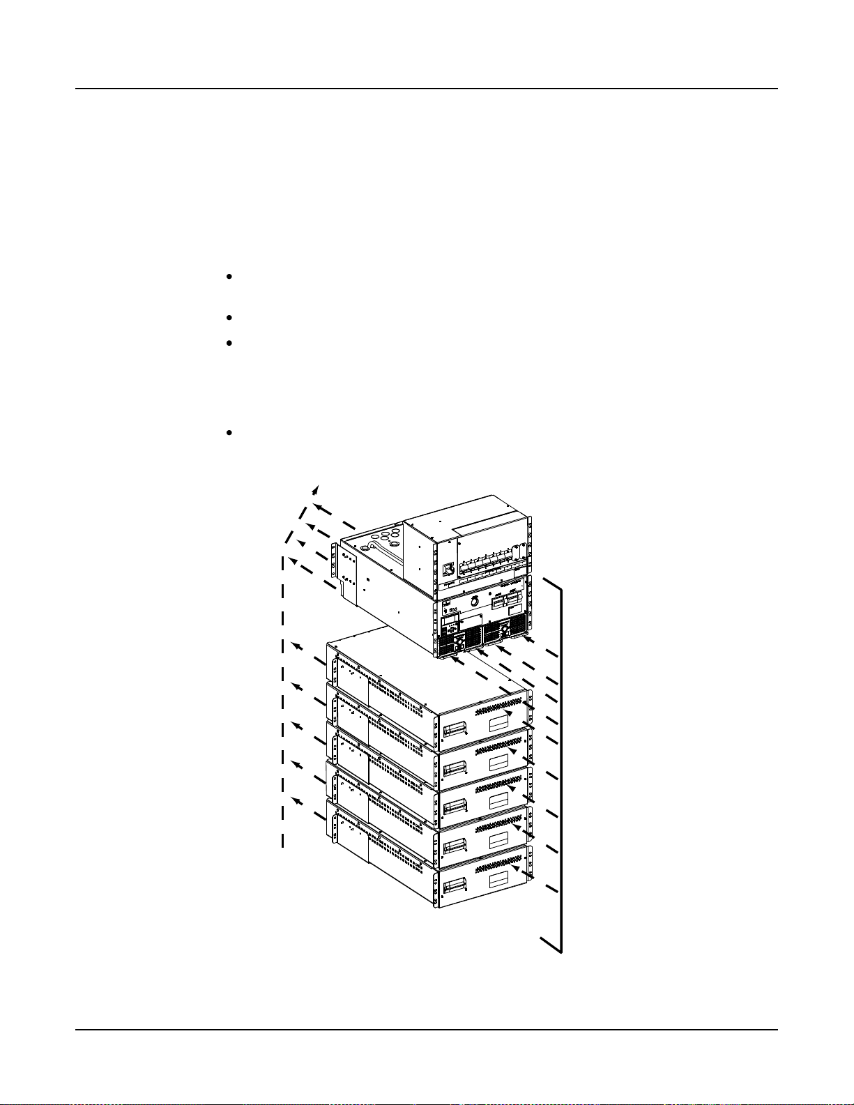
Installing the Sub-Racks
If the system was ordered to be installed in a customer provided IT rack, install the
individual components of the DC Power System into a 19” mounting frame of the IT rack.
Procedure
Note: Refer to Figure 2-2 as this procedure is performed.
1) If furnished, the DC load distribution sub-rack(s) is typically installed at the top of
the IT rack.
Note: The system can consist of 0-2 DC load distribution sub-rack(s).
a) Slide the DC load distribution sub-rack into position and secure the front
mounting flanges to the IT rack with the furnished cage nuts and screws.
b) Repeat this procedure if a second DC load distribution sub-rack is furnished.
2) The power and control sub-rack is typically installed below the DC load
distribution sub-rack(s).
Note: The system consists of one (1) power and control sub-rack.
a) Secure the rear mounting brackets to the IT rack with the furnished cage nuts
and screws.
b) Remove the rear cover from the power and control sub-rack.
c) Slide the power and control sub-rack into the front of the IT rack until it is in
position (with the bottom of the sub-rack resting on the angles of the rear
mounting brackets).
d) Secure the front mounting flanges to the IT rack with the furnished cage nuts
and screws.
Page 10 Chapter 2. Installing the System
This document is property of Emerson Network Power, Energy Systems, North America, Inc. and contains confidential and proprietary information owned by Emerson Network Power, Energy
Systems, North America, Inc. Any copying, use, or disclosure of it without the written permission of Emerson Network Power, Energy Systems, North America, Inc. is strictly prohibited.
Page 21

Installation Instructions IM584000300
Spec. No. 584000300 (Model 4015-X003) Issue AB, April 3, 2013
e) Secure the rear mounting brackets to the power and control sub-rack with the
furnished hardware (hardware is installed from inside the sub-rack, the rear
mounting brackets have captive fasteners).
3) If furnished, the battery tray(s) is typically installed at the bottom of the IT rack
due to the weight of the batteries.
Note: Only install the battery tray(s) at this time. Battery sub-trays (with
batteries) will be installed in the “Making Electrical Connections” section.
Note: The system can consist of 0-5 battery tray(s).
Note: Battery cables from the battery tray(s) can enter the power and control
sub-rack from either the top or bottom of the power and control sub-rack.
Note that a space is required between the power and control sub-rack
and battery tray to allow the cables to enter from the bottom.
a) Secure the rear mounting brackets to the IT rack with the furnished cage nuts
and screws.
b) Slide the battery tray into the front of the IT rack until it is in position (with the
bottom of the sub-rack resting on the angles of the rear mounting brackets).
c) Secure the front mounting flanges to the IT rack with the furnished cage nuts
and screws.
d) Secure the rear mounting brackets to the battery tray with the furnished
hardware (hardware is installed from inside the battery tray, the rear
mounting brackets have captive fasteners).
e) Repeat this procedure if other battery tray(s) are furnished.
Chapter 2. Installing the System Page 11
This document is property of Emerson Network Power, Energy Systems, North America, Inc. and contains confidential and proprietary information owned by Emerson Network Power, Energy
Systems, North America, Inc. Any copying, use, or disclosure of it without the written permission of Emerson Network Power, Energy Systems, North America, Inc. is strictly prohibited.
Page 22

IM584000300 Installation Instructions
Front
Use supplied IT cage nut/screw for mounting.
(3) per side for the distribution sub-rack(s).
(4) per side (front and rear brackets) for the power and control sub-rack.
(3) per side (front and rear brackets) for the battery tray(s).
Front Mounting
Flanges (both sides)
Rear Mounting
Brackets Bottom
Angles
The rear mounting bracket can be adjusted from 28.75” (730mm) to 32.25” (819mm)
for the Power and Control Sub-Rack and 26.39” (670mm) to 32.60” (828mm)
for the Batter Tray.
Rear Mounting Brackets (both sides)
(Secure rear mounting brackets to ITrackfirst,
then slide sub-rack into IT rack so sub-rack
rests on rear mounting brackets bottom angles,
then secure sub-rack’s front mounting flanges
to IT rack, and finally secure rear mounting
brackets to sub-rack.)
Remove back cover to secure rear mounting brackets,
hardware is installed from inside the sub-rack,
the brackets have captive fasteners to secure hardware.
Load Distribution
Sub-Rack
Power and Control
Sub-Rack
Battery
Tray
Issue AB, April 3, 2013 Spec. No. 584000300 (Model 4015-X003)
Electrically Interconnecting the Sub-Rack(s)
The sub-racks are electrically interconnected later in the “Sub-Racks Electrical
Interconnections” procedure on page 21.
Figure 2-2
Mounting Details
Page 12 Chapter 2. Installing the System
This document is property of Emerson Network Power, Energy Systems, North America, Inc. and contains confidential and proprietary information owned by Emerson Network Power, Energy
Systems, North America, Inc. Any copying, use, or disclosure of it without the written permission of Emerson Network Power, Energy Systems, North America, Inc. is strictly prohibited.
Page 23

Installation Instructions IM584000300
Spec. No. 584000300 (Model 4015-X003) Issue AB, April 3, 2013
CHAPTER 3. MAKING ELECTRICAL CONNECTIONS
IMPORTANT SAFETY INSTRUCTIONS
Danger: Adhere to the “Important Safety Instructions” presented at the front of
this document.
WIRING CONSIDERATIONS
All AC input and 400V DC output wiring, branch circuit protection, and grounding should
follow the current edition of the American National Standards Institute (ANSI) approved
National Fire Protection Association's (NFPA) National Electrical Code (NEC), and
applicable local codes. For operation in countries where the NEC is not recognized,
follow applicable codes.
For wire size, branch circuit protection, crimp lug, and general wiring
recommendations; refer to System Application Guide SAG584000300.
TORQUE
Torque all connections as specified in the illustrations presented in this chapter.
OUTPUT GROUND CONFIGURATIONS
These instructions apply both to the High Resistance Midpoint Grounded (HRMG) and
Negative Pole Grounded (NPG) configurations. Ensure you follow the proper procedures
for the configuration you have. Refer to the part number on your equipment. The table
on the front cover of this document lists the various equipment part numbers and the
configuration they apply to.
CABLE ROUTING
When System is Furnished in a Factory Provided IT Rack (List R1, R2)
If the system is furnished in a factory provided IT rack, connections between the system’s
sub-racks and also to the IT rack ground bar are factory made. The electrical
connections the customer is required to make are the following. Refer to Figure 3-1 on
the next page for a cable routing diagram.
Site Ground to IT Rack Ground Bar (page 25)
AC Input Connections (page 28)
DC Load Distribution Connections to List 21-24 Distribution Sub-Rack(s) (page 29)
Battery Sub-Trays Installed in List 91-92 Battery Tray(s) (page 31)
External Batteries (if required) (page 33)
IB2 (ACU+ Controller Interface Board) Connections (if required) (page 35)
ACU+ Controller Ethernet Connection (if required) (page 36)
Power and Control Sub-Rack Bulk Output Connections (if required) (page 40)
GO TO PAGE 25 FOR THE ELECTRICAL CONNECTIONS PROCEDURES.
Chapter 3. Making Electrical Connections Page 13
This document is property of Emerson Network Power, Energy Systems, North America, Inc. and contains confidential and proprietary information owned by Emerson Network Power, Energy
Systems, North America, Inc. Any copying, use, or disclosure of it without the written permission of Emerson Network Power, Energy Systems, North America, Inc. is strictly prohibited.
Page 24

IM584000300 Installation Instructions
Note: Cables can also be
fed from bottom for raised
floor applications.
Emerson Network
Power DCM IT Rack
* Ground Bar Provided
on Rear of IT Rack
Top Plate
Two options available:
1) P/N 554472.
Holes sized for imperial conduit fittings
(25mm [1”] conduit fittings except AC Input and External
Battery which are 32mm [1.25”] conduit fittings).
2) P/N 554473.
Holes sized for corded connections
using metric cord grips (38mm [1.5”] holes).
AC #1
DC Loads
AC #2
External Battery 1
External Battery 2
Building Ground *
Alarm
Front
Rear
Battery Leads Openings
for 19mm (0.75”) Conduit
(top and bottom)
Distribution
Sub-Rack
Power and
Control
Sub-Rack
Battery
Tray
DC Distribution Leads Openings
for 25mm (1”) Conduit
(snap bushings are furnished
for use without conduit)
AC Input Leads Opening
for 25mm (1”) Conduit
Alarm Leads Opening
for 25mm (1”) Conduit
Issue AB, April 3, 2013 Spec. No. 584000300 (Model 4015-X003)
Top Feed Cable Landing Diagram – Factory Provided IT Rack
Page 14 Chapter 3. Making Electrical Connections
This document is property of Emerson Network Power, Energy Systems, North America, Inc. and contains confidential and proprietary information owned by Emerson Network Power, Energy
Systems, North America, Inc. Any copying, use, or disclosure of it without the written permission of Emerson Network Power, Energy Systems, North America, Inc. is strictly prohibited.
Figure 3-1
Page 25

Installation Instructions IM584000300
Spec. No. 584000300 (Model 4015-X003) Issue AB, April 3, 2013
When System Components are Furnished Loose to be Installed in a Customer Furnished IT Rack
If the system components are furnished loose to be installed in a customer furnished IT
rack, the following connections are required. Refer to Figure 3-2 for a cable routing
diagram.
Grounding Connections between the Sub-Racks and the IT Rack Ground Bar (page
17)
Return Bar Grounding Connection (NPG Configurations Only) (page 17)
HRMG Grounding Connection (HRMG Configurations Only) (page 17)
Sub-Racks Electrical Interconnections (page 21)
Site Ground to IT Rack Ground Bar (page 25)
AC Input Connections (page 28)
DC Load Distribution Connections to List 21-24 Distribution Sub-Rack(s) (page 29)
Battery Sub-Trays Installed in List 91-92 Battery Tray(s) (page 31)
External Batteries (if required) (page 33)
IB2 (ACU+ Controller Interface Board) Connections (if required) (page 35)
ACU+ Controller Ethernet Connection (if required) (page 36)
Power and Control Sub-Rack Bulk Output Connections (if required) (page 40)
Chapter 3. Making Electrical Connections Page 15
This document is property of Emerson Network Power, Energy Systems, North America, Inc. and contains confidential and proprietary information owned by Emerson Network Power, Energy
Systems, North America, Inc. Any copying, use, or disclosure of it without the written permission of Emerson Network Power, Energy Systems, North America, Inc. is strictly prohibited.
Page 26

IM584000300 Installation Instructions
Removable
Panel
Power and Control Sub-Rack DC
Output Leads to Distribution Sub-Rack
to Power and Control
Sub-Rack Battery Terminals
Return Bar Grounding Point
(19mm [0.75"] Conduit Opening)
(NPG Configurations Only)
Note: This connection can be
made here or on the power
and control sub-rack.
Rear
Power and Control Sub-Rack
DC Output Leads Openings
for 32mm (1.25”) Conduit
Battery Leads Openings for
19mm (0.75”) Conduit
(top and bottom)
Distribution
Sub-Rack
Power and
Control
Sub-Rack
Battery
Tray
DC Distribution Leads Openings
for 25mm (1”) Conduit
(snap bushings are furnished
for use without conduit)
AC Input Leads Opening
for 25mm (1”) Conduit
Alarm Leads Opening
for 25mm (1”) Conduit
Issue AB, April 3, 2013 Spec. No. 584000300 (Model 4015-X003)
Page 16 Chapter 3. Making Electrical Connections
This document is property of Emerson Network Power, Energy Systems, North America, Inc. and contains confidential and proprietary information owned by Emerson Network Power, Energy
Systems, North America, Inc. Any copying, use, or disclosure of it without the written permission of Emerson Network Power, Energy Systems, North America, Inc. is strictly prohibited.
Figure 3-2
Individual Cable Landing Points – Sub-Racks
Page 27

Installation Instructions IM584000300
Spec. No. 584000300 (Model 4015-X003) Issue AB, April 3, 2013
TASKS TO BE PERFORMED FOR CUSTOMER INTEGRATED SYSTEMS
ALSO MAKE THE CONNECTIONS DESCRIBED UNDER “Tasks to Be Perform for All
Installations” STARTING ON PAGE 25.
Grounding
Danger: Failure to follow proper grounding procedures can result in electric shock
hazard to personnel or the risk of fire, should a ground fault occur.
For grounding requirements, refer to the current edition of the American National
Standards Institute (ANSI) approved National Fire Protection Association's (NFPA)
National Electrical Code (NEC), applicable local codes, and your specific site
requirements. For operation in countries where the NEC is not recognized, follow
applicable codes.
Refer to Figure 3-8 for a complete system grounding scheme diagram.
Sub-Rack Grounding (Frame Ground)
When individual system components are furnished, the individual components must be
grounded on site by the customer after installation into an IT rack. A cabinet grounding
stud is located on the rear of the power and control sub-rack and distribution sub-rack. A
tray grounding stud is located on the rear side panel of the battery tray. Refer to Figure
3-3 for connection points.
NPG Configurations Only: Return Busbar (-Bus) Grounding Connection
The return busbar (–Bus) in a negative pole ground (NPG) configuration is to be
connected to ground. A grounding connection point for the return busbar (-Bus) is
provided on the negative bus in the power and control sub-rack. This connection can
also be made on the rear of the load distribution sub-rack, if furnished. Only connect in
one place. Refer to Figure 3-4 for connection points.
HRMG Configurations Only: Bus Grounding Connection
A lead exits the rear of the power and control sub-rack in a High Resistance Midpoint
Ground (HRMG) configuration. This lead MUST be connected directly to ground for
proper operation of the mid-point grounding circuit and the ground fault detection circuit.
Refer to Figure 3-5 for connection point.
Caution: Failure to terminate this conductor to ground will render the system
ground fault detection circuit and the ±200V DC voltage reference
inoperable. It is essential to properly bond this lead to ground.
Note: This lead is 16 AWG, approximately 100” long, and terminated in a ring lug with a
1/4” clearance hole.
Chapter 3. Making Electrical Connections Page 17
This document is property of Emerson Network Power, Energy Systems, North America, Inc. and contains confidential and proprietary information owned by Emerson Network Power, Energy
Systems, North America, Inc. Any copying, use, or disclosure of it without the written permission of Emerson Network Power, Energy Systems, North America, Inc. is strictly prohibited.
Page 28

IM584000300 Installation Instructions
Load Distribution
Sub-Rack
Rear View
Rear
Sub-Rack Grounding
Stud (1/4-20 x 9/16”)
(Recommended Torque:
84 in-lbs [9 Nm])
Tray Grounding
Stud (1/4-20 x 1/2”)
(Recommended Torque:
84 in-lbs [9 Nm])
Battery Tray
Rear View
(covers removed)
Sub-Rack Grounding
Stud (1/4-20 x 5/8”)
(Recommended Torque:
84 in-lbs [9 Nm])
Power and
Control
Sub-Rack
Issue AB, April 3, 2013 Spec. No. 584000300 (Model 4015-X003)
Page 18 Chapter 3. Making Electrical Connections
This document is property of Emerson Network Power, Energy Systems, North America, Inc. and contains confidential and proprietary information owned by Emerson Network Power, Energy
Systems, North America, Inc. Any copying, use, or disclosure of it without the written permission of Emerson Network Power, Energy Systems, North America, Inc. is strictly prohibited.
Figure 3-3
Sub-Racks Frame Grounding Connections
Page 29

Installation Instructions IM584000300
Load Distribution Sub-Rack
Rear View
Rear View
(covers removed)
Power and Control Sub-Rack
Return Busbar (-Bus)
Grounding Point
(NPG Configurations Only)
Note: This connection can be made
here or on the distribution sub-rack
(if furnished) as shown above.
(one set of 1/4-20 x 1/2”
studs on 5/8” centers
for double hole lugs)
(Recommended Torque:
84 in-lbs [9 Nm])
Caution: In the NPG Configuration,
this equipment will have (after installation)
a connection between the earthed conductor
of the DC power supply circuit and the earthing
conductor.
Return Busbar (-Bus)
Grounding Point
(cover removed)
(NPG Configurations Only)
Note: This connection can be
made here or on the power
and control sub-rack as
shown below.
(Wire Size Capacity:
10AWG to 4 AWG)
(Recomended Torque:
80 in-lbs [9 Nm])
Spec. No. 584000300 (Model 4015-X003) Issue AB, April 3, 2013
Return Busbar (-Bus) Grounding Connection (NPG Configurations Only)
Figure 3-4
Chapter 3. Making Electrical Connections Page 19
This document is property of Emerson Network Power, Energy Systems, North America, Inc. and contains confidential and proprietary information owned by Emerson Network Power, Energy
Systems, North America, Inc. Any copying, use, or disclosure of it without the written permission of Emerson Network Power, Energy Systems, North America, Inc. is strictly prohibited.
Page 30

IM584000300 Installation Instructions
Rear View
(covers removed)
Power and Control Sub-Rack
HRMG Ground Connection
(HRMG Configurations Only)
(MUST BE PROPERLY
CONNECTED TO GROUND)
Alead exits the rear of the power and control sub-rack in a
High Resistance Midpoint Ground (HRMG) configuration.
This lead MUST be connected directly to ground for proper
operation of the mid-point grounding circuit and the ground
fault detection circuit. This lead is 16AWG, approximately
100” long, and terminated in a ring lug with a 1/4” clearance hole.
Issue AB, April 3, 2013 Spec. No. 584000300 (Model 4015-X003)
Figure 3-5
HRMG Ground Connection (HRMG Configuration Only)
Page 20 Chapter 3. Making Electrical Connections
This document is property of Emerson Network Power, Energy Systems, North America, Inc. and contains confidential and proprietary information owned by Emerson Network Power, Energy
Systems, North America, Inc. Any copying, use, or disclosure of it without the written permission of Emerson Network Power, Energy Systems, North America, Inc. is strictly prohibited.
Page 31

Installation Instructions IM584000300
Spec. No. 584000300 (Model 4015-X003) Issue AB, April 3, 2013
Sub-Racks Electrical Interconnections
If the system components are furnished loose to be installed in a customer furnished IT
rack, the following electrical interconnections are required.
Connecting the Load Distribution Sub-Rack(s) to the Power and Control Sub-Rack
Note: If you are connecting “bulk” loads, refer to “Power and Control Sub-Rack Bulk
Output Connections (if required)” on page 40.
Procedure
1) Locate the load distribution sub-rack input cables which are factory connected to
the load distribution sub-rack. Route these cables into the power and control
sub-rack. Connect these cables to the DC output terminals located inside the
power and control sub-rack as follows. Repeat this procedure if a second load
distribution sub-rack is furnished. Refer to Figure 3-6.
Connect the cable labeled /+/ to the positive DC output terminals.
Connect the cable labeled /-/ to the negative DC output terminals.
Connecting the Battery Tray(s) to the Power and Control Sub-Rack
Procedure
1) Locate the battery tray output cables which are factory connected to the battery
tray. Route these cables into the power and control sub-rack. Cables can be
routed from the top or bottom into the power and control sub-rack. Connect
these leads to the battery terminals located inside the power and control sub-rack
as follows. Repeat this procedure if additional battery trays are furnished. Refer
to Figure 3-6.
Connect the cable labeled /+/ to the positive battery terminals.
Connect the cable labeled /-/ to the negative battery terminals.
Connecting the Battery Tray Control and Alarm Harness to Other Battery Trays and/or to the Power and Control Sub-Rack
Procedure
1) If only one battery tray is furnished, locate the control/alarm wire harness exiting
the battery tray. Locate the two (2) battery control/alarm connectors located on
the rear of the power and control sub-rack. Remove a termination plug from one
of these connectors. Connect the extension control/alarm cable between the
battery tray control/alarm wire harness and the power and control sub-rack
connector which the termination plug was removed from. Refer to Figure 3-7.
2) If more than one battery tray is furnished, use the supplied battery tray
control/alarm daisy chain cable as shown in Figure 3-7.
Chapter 3. Making Electrical Connections Page 21
This document is property of Emerson Network Power, Energy Systems, North America, Inc. and contains confidential and proprietary information owned by Emerson Network Power, Energy
Systems, North America, Inc. Any copying, use, or disclosure of it without the written permission of Emerson Network Power, Energy Systems, North America, Inc. is strictly prohibited.
Page 32

IM584000300 Installation Instructions
Load Distribution Sub-Rack DC Input Cables
(Factory connected in load distribution sub-rack,
customer to route into power and control
sub-rack and connect to power and control
sub-rack DC output terminals.)
Battery Tray Output Cables
(Factory connected in battery tray,
customer to route into power and
control sub-rack and connect to
power and control sub-rack battery
terminals.)
Rear
Load
Distribution
Sub-Rack
Power and
Control
Sub-Rack
Battery
Tray
*Note: Battery cables can also be
routed through the bottom of the
power and control sub-rack.
Battery Terminals
for 400V DC Battery Strings
(five sets of 1/4-20 x 5/8”
studs on 5/8” centers for
double hole lugs,
each polarity)
Rear View
(covers removed)
Negative
Battery*
Positive
Battery*
++
--
(Recommended
Torque: 84 in-lbs
[9 Nm])
Power and
Control
Sub-Rack
(Recommended
Torque: 84 in-lbs
[9 Nm])
400V DC Output Terminals
(two sets of 1/4-20 x 5/8”
studs on 5/8” centers for
double hole lugs,
each polarity)
Negative
Output
Positive
Output
Issue AB, April 3, 2013 Spec. No. 584000300 (Model 4015-X003)
Figure 3-6
Sub-Rack Interconnections
Page 22 Chapter 3. Making Electrical Connections
This document is property of Emerson Network Power, Energy Systems, North America, Inc. and contains confidential and proprietary information owned by Emerson Network Power, Energy
Systems, North America, Inc. Any copying, use, or disclosure of it without the written permission of Emerson Network Power, Energy Systems, North America, Inc. is strictly prohibited.
Page 33

Installation Instructions IM584000300
Internal/External Battery Tray
Control/Alarm Connectors
(If an internal or external battery tray is
not connected, MUST have termination
plugs installed.) (Use either connector.)
1. Remove a termination plug from one of the
connectors (either one) located on the rear
of the power and control sub-rack.
2. Plug the extension control/alarm cable
into the connector the termination plug was
removed from.
3. Connect the other end of the extension
control/alarm cable into the battery tray
control/alarm harness.
Rear
Rear
Battery Tray
Control/Alarm
Harness
Extension
Control/Alarm
Cable (P/N 554715)
(56”)
Power and Control
Sub-Rack
Battery Tray Alarm / Control Connections - 1 Tray Only
Battery
Tray
Spec. No. 584000300 (Model 4015-X003) Issue AB, April 3, 2013
Figure 3-7 (cont’d on next page)
Internal Battery Tray Interconnections
Chapter 3. Making Electrical Connections Page 23
This document is property of Emerson Network Power, Energy Systems, North America, Inc. and contains confidential and proprietary information owned by Emerson Network Power, Energy
Systems, North America, Inc. Any copying, use, or disclosure of it without the written permission of Emerson Network Power, Energy Systems, North America, Inc. is strictly prohibited.
Page 34

IM584000300 Installation Instructions
Battery Tray
Control/Alarm
Daisy Chain Cable
(P/N 553614)
Internal/External Battery Tray
Control/Alarm Connectors
(If an internal or external battery tray is
not connected, MUST have termination
plugs installed.) (Use either connector.)
1. Remove a termination plug from one of the
connectors (either one) located on the rear
of the power and control sub-rack.
2. Plug the extension control/alarm cable
into the connector the termination plug was
removed from.
3. Connect the other end of the extension
control/alarm cable into the end of the
battery tray control/alarm daisy chain cable.
4. Plug the center connector of the battery tray
control/alarm daisy chain cable into the battery
tray control/harness of the first battery tray.
5. Plug the remaining end of the battery tray
control/alarm daisy chain cable into the battery
tray control/harness of the second battery tray.
Rear
Rear
Battery Tray
Control/Alarm
Harness
Power and Control
Sub-Rack
Battery
Tray
Rear
Battery Tray
Control/Alarm
Harness
Battery
Tray
Extension
Control/Alarm
Cable (P/N 554715)
(56”)
Battery TrayAlarm / Control Connections - 2 or More Trays
Issue AB, April 3, 2013 Spec. No. 584000300 (Model 4015-X003)
Page 24 Chapter 3. Making Electrical Connections
This document is property of Emerson Network Power, Energy Systems, North America, Inc. and contains confidential and proprietary information owned by Emerson Network Power, Energy
Systems, North America, Inc. Any copying, use, or disclosure of it without the written permission of Emerson Network Power, Energy Systems, North America, Inc. is strictly prohibited.
Figure 3-7 (cont’d from previous page)
Internal Battery Tray Interconnections
Page 35

Installation Instructions IM584000300
Spec. No. 584000300 (Model 4015-X003) Issue AB, April 3, 2013
TASKS TO BE PERFORM FOR ALL INSTALLATIONS
Grounding
Danger: Failure to follow proper grounding procedures can result in electric shock
hazard to personnel or the risk of fire, should a ground fault occur.
For grounding requirements, refer to the current edition of the American National
Standards Institute (ANSI) approved National Fire Protection Association's (NFPA)
National Electrical Code (NEC), applicable local codes, and your specific site
requirements. For operation in countries where the NEC is not recognized, follow
applicable codes.
Refer to Figure 3-8 for a complete system grounding scheme diagram.
IT Rack Grounding (Frame Ground)
Supply a grounding lead from site ground to the IT rack ground bar. For factory
integrated systems (List R1, R2), refer to Figure 3-9 for connection point.
Note: When the system is furnished in an IT rack, grounding leads are factory wired
from the individual system components to a ground bar located on the rear left
side of the furnished IT rack.
Conduit Grounding (Frame Ground)
Conduit grounding points are provided on terminal strips located on the left and right
inside side walls of the distribution sub-rack. Refer to Figure 3-9 for connection points.
Chapter 3. Making Electrical Connections Page 25
This document is property of Emerson Network Power, Energy Systems, North America, Inc. and contains confidential and proprietary information owned by Emerson Network Power, Energy
Systems, North America, Inc. Any copying, use, or disclosure of it without the written permission of Emerson Network Power, Energy Systems, North America, Inc. is strictly prohibited.
Page 36

IM584000300 Installation Instructions
NPG System Grounding
HRMG System Grounding
DC Load Distribution
Sub-Rack
Power & Control
Sub-Rack
Battery Tray
AC Input
HRMG Ground
Connection
IT Rack
Main
Ground Bar
To Building
Facility Ground
Rack Frame Ground
Tray 2-5
NOTES:
1. Refer to SAG584000300
for recommended ground
lead wire sizes.
NOTES:
1. Refer to SAG584000300
for recommended ground
lead wire sizes.
2. -400V DC Return
can be either
connected to the
-Bus or DC Distribution
Sub-Rack.
System Grounding Connections Overview
±200V DC
Load Wiring
+ -
Conduit Gnd
(if req’d)
DC Load Distribution
Sub-Rack
Power & Control
Sub-Rack
Battery Tray
AC Input
IT Rack
Main
Ground Bar
To Building
Facility Ground
Rack Frame Ground
Tray 2-5
400V DC
Load Wiring
+ -
Conduit Gnd
(if req’d)
Note 2
- BUS
IT Rack
IT Rack
Issue AB, April 3, 2013 Spec. No. 584000300 (Model 4015-X003)
Page 26 Chapter 3. Making Electrical Connections
This document is property of Emerson Network Power, Energy Systems, North America, Inc. and contains confidential and proprietary information owned by Emerson Network Power, Energy
Systems, North America, Inc. Any copying, use, or disclosure of it without the written permission of Emerson Network Power, Energy Systems, North America, Inc. is strictly prohibited.
Figure 3-8
Grounding Scheme Diagram
Page 37

Installation Instructions IM584000300
Rear
Emerson Network Power
DCM IT Rack
Ground Bar
(1/4-20 Captive Nuts
on 5/8” Centers)
(Recommended Torque:
84 in-lbs [9 Nm])
To
Site
Ground
To IT Rack
Frame Ground
Suggested
Connection
Points
To Sub-Rack(s)
Grounding Stud
To HRMG Ground
(if required)
To NPG Ground
(if required)
Conduit Grounding Points
(Stripped Wire Type Connection)
(Wire Size Capacity: see below)
(Recommended Torque: see below)
14-10AWG (2.5-6mm2) 20 in-lbs (2 Nm)
8 AWG (10mm2) 25 in-lbs (3 Nm)
6-4 AWG (16-25mm2) 35 in-lbs (4 Nm)
Load Distribution
Sub-Rack
Front View
(covers removed)
Spec. No. 584000300 (Model 4015-X003) Issue AB, April 3, 2013
Figure 3-9
IT Rack and Conduit Grounding Connections
Chapter 3. Making Electrical Connections Page 27
This document is property of Emerson Network Power, Energy Systems, North America, Inc. and contains confidential and proprietary information owned by Emerson Network Power, Energy
Systems, North America, Inc. Any copying, use, or disclosure of it without the written permission of Emerson Network Power, Energy Systems, North America, Inc. is strictly prohibited.
Page 38

IM584000300 Installation Instructions
++
--
Power and Control Sub-Rack
Rectifier Shelf Rear View
(covers removed)
AC Input
Ground Lead
Stud (10-32 x 5/16”)
(Recommended
Torque: 23 in-lbs
[3 Nm])
A B C
AC Input
Nominal 380V/400V/480V AC,
Three-Phase, 50/60 Hz.
(Wire Size Capacity: see below)
(Recommended Torque:see below)
2-3 AWG (35-30mm2) 50 in-lbs (5.65 Nm)
4-6 AWG (25-16mm2) 45 in-lbs (5.08 Nm)
Issue AB, April 3, 2013 Spec. No. 584000300 (Model 4015-X003)
AC Input Power Connections
Danger: Adhere to the “Important Safety Instructions” presented at the front of
this document. DO NOT attempt to work on an energized system.
AC input connections are made to an AC input terminal block located behind an access
panel located on the rear of the power and control sub-rack. Studs are also provided for
the AC Input ground leads. Refer to Figure 3-10 for location and connection details.
Figure 3-10
AC Input Power Connections
Page 28 Chapter 3. Making Electrical Connections
This document is property of Emerson Network Power, Energy Systems, North America, Inc. and contains confidential and proprietary information owned by Emerson Network Power, Energy
Systems, North America, Inc. Any copying, use, or disclosure of it without the written permission of Emerson Network Power, Energy Systems, North America, Inc. is strictly prohibited.
Page 39

Installation Instructions IM584000300
Spec. No. 584000300 (Model 4015-X003) Issue AB, April 3, 2013
DC Load Distribution Electrical Connections to List 21-24 DC Load Distribution Sub-Rack(s) (if furnished)
Danger: Adhere to the “Important Safety Instructions” presented at the front of
this document. DO NOT attempt to work on an energized system.
Warning: Check for correct polarity before making connections.
HRMG (High Resistance Midpoint Ground) Configuration
Load distribution leads are connected to the load distribution devices as shown in Figure
3-11.
NPG (Negative Pole Ground) Configuration
Load distribution leads are connected to the load distribution devices and return busbar
as shown in Figure 3-11. Note that the return busbar is connected to ground as
described in “NPG Configurations Only: Return Busbar (-Bus) Grounding Connection on
page 17.
Chapter 3. Making Electrical Connections Page 29
This document is property of Emerson Network Power, Energy Systems, North America, Inc. and contains confidential and proprietary information owned by Emerson Network Power, Energy
Systems, North America, Inc. Any copying, use, or disclosure of it without the written permission of Emerson Network Power, Energy Systems, North America, Inc. is strictly prohibited.
Page 40

IM584000300 Installation Instructions
Load Distribution Sub-Rack
(HRMG Configurations)
Load Distribution Sub-Rack
(NPG Configurations)
Load Connections
(See Detail A)
(Stripped Wire
Type Connection)
Load Connections
(See Detail B)
(Stripped Wire
Type Connection)
DETAILA
Load Connections to
Load Distribution Circuit Breakers
Front
(cover removed)
+
-
Wire Size Capacity:
10-4 AWG (6-25mm2)
Recomended Torque:
18 in-lbs (2 Nm)
±200V DC
factory
connection
Wire Size Capacity:
10-4 AWG (6-25mm2)
Recomended Torque:
80 in-lbs [9 Nm])
Return (-)
Return Bar
+400V DC
Front
(cover removed)
DETAIL B
Load Connections to
Load Distribution Circuit Breakers and Return Bar
Wire Size Capacity:
10-4 AWG (6-25mm2)
Recomended Torque:
18 in-lbs (2 Nm)
Field Connection to
External Customer Loads.
OBSERVE CORRECT POLARITY.
Field Connection to
External Customer Loads.
OBSERVE CORRECT POLARITY.
CONNECT ONLYTO "+"
SIDE OF BREAKER,
AS SHOWN.
Caution: In the NPG Configuration,
this equipment will have (after installation)
a connection between the earthed conductor
of the DC power supply circuit and the earthing
conductor.
Issue AB, April 3, 2013 Spec. No. 584000300 (Model 4015-X003)
Page 30 Chapter 3. Making Electrical Connections
This document is property of Emerson Network Power, Energy Systems, North America, Inc. and contains confidential and proprietary information owned by Emerson Network Power, Energy
Systems, North America, Inc. Any copying, use, or disclosure of it without the written permission of Emerson Network Power, Energy Systems, North America, Inc. is strictly prohibited.
Figure 3-11
DC Load Distribution Connections to Distribution Sub-Rack(s)
Page 41

Installation Instructions IM584000300
Battery Sub-Tray
Connector
Red +
Black -
Spec. No. 584000300 (Model 4015-X003) Issue AB, April 3, 2013
Installing Battery Sub-Trays in List 91 and 92 Battery Tray(s) (if furnished)
Danger: Adhere to the “Important Safety Instructions” presented at the front of
this document.
Warning: Ensure battery breaker on front of battery tray is turned off and locked-
out before beginning work.
Warning: The battery tray is pre-wired with output battery cables with exposed
ends. DO NOT install batteries into a battery tray that is not wired into
the power and control sub-rack.
Battery Manufacturer Information
Refer to System Application Guide SAG584000300 for specifications and manufacturers
of the batteries to be installed in this power system.
Installing Battery Sub-Trays
Batteries are furnished with this system but shipped separately. These batteries are
packaged in six (6) battery sub-trays. All battery wiring within the battery sub-trays are
done at the factory.
Procedure
Refer to Figure 3-12 as this procedure is performed.
1) ENSURE BATTERY BREAKER ON FRONT OF BATTERY TRAY IS TURNED
OFF AND LOCKED-OUT.
2) Remove the battery retaining bracket from the rear of the battery tray.
3) Unpack the battery sub-trays.
4) In the battery sub-trays that hold five (5) batteries, one battery string cable is
disconnected and sleeved at the factory for transportation. Locate this lead and
connect it to the open battery terminal in that tray. See Figure 3-12.
5) Check each battery sub-tray voltage before installing as follows.
a) Battery sub-trays contain either four (4) or five (5) pre-wired battery blocks.
Note that the minimum acceptable voltage of a single battery block is 11.5V
DC. So, acceptable voltage of a battery sub-tray with four (4) battery blocks
is 11.5V x 4 = 46V DC. Acceptable voltage of a battery sub-tray with five (5)
battery blocks is 11.5V x 5 = 57.5V DC.
b) With an external meter, measure each battery sub-tray voltage at the battery
sub-tray connector (see illustration in left margin). If battery sub-tray
voltages are OK, install each battery sub-tray as detailed in the remaining
steps of this procedure. Contact Emerson Technical Support if battery subtray voltages are not within limits. Contact information is provided on the
inside back cover of this document.
6) If a battery temperature probe is to be used, it is recommended to secure it on
top of a battery block near the location indicated in Figure 3-12.
7) Slide pre-wired battery sub-trays into battery tray.
8) Connect each battery sub-tray connector to the respective connector located on
the battery tray.
9) Re-install the battery retaining bracket to the battery tray.
Chapter 3. Making Electrical Connections Page 31
This document is property of Emerson Network Power, Energy Systems, North America, Inc. and contains confidential and proprietary information owned by Emerson Network Power, Energy
Systems, North America, Inc. Any copying, use, or disclosure of it without the written permission of Emerson Network Power, Energy Systems, North America, Inc. is strictly prohibited.
Page 42

IM584000300 Installation Instructions
Battery Sub-Trays
Battery Tray
Battery Tray
Battery
Retaining
Bracket
On the sub-trays that hold five (5)
batteries, one battery string cable
is disconnected and sleeved at the
factory. Locate this lead and connect
it to the open battery terminal in that tray.
Battery tray output cables
not shown for clarity.
Note: Battery tray must be
installed in rack before
installing batteries.
Rear
Battery Sub-Tray Connector
Battery wiring connectorized
for easy installation.
If a battery temperature probe
is to be used, it is recommended
to secure it on top of a battery
block near this location.
Battery Tray Connector
X
Issue AB, April 3, 2013 Spec. No. 584000300 (Model 4015-X003)
Figure 3-12
Installing Battery Sub-Trays in List 91 and 92 Battery Tray(s)
Page 32 Chapter 3. Making Electrical Connections
This document is property of Emerson Network Power, Energy Systems, North America, Inc. and contains confidential and proprietary information owned by Emerson Network Power, Energy
Systems, North America, Inc. Any copying, use, or disclosure of it without the written permission of Emerson Network Power, Energy Systems, North America, Inc. is strictly prohibited.
Page 43

Installation Instructions IM584000300
Spec. No. 584000300 (Model 4015-X003) Issue AB, April 3, 2013
External Battery Connections (if required)
Danger: Adhere to the “Important Safety Instructions” presented at the front of
this document. DO NOT attempt to work on an energized system.
Warning: Observe proper polarity when making battery connections.
Up to five internal or external battery strings can be connected to busbars located in the
power and control sub-rack. If the system is furnished in a factory provided IT rack,
connections to internal battery trays are factory made.
Connect any external battery strings to the positive and negative battery connection
points per Figure 3-13. Cables can be routed from the top or bottom to the power and
control sub-rack. Refer to SAG584000300 for wire size and crimp lug information.
If there is a battery breaker associated with the external battery string that is to be
controlled (tripped) by the system’s LVD circuit, wire per Figure 3-13.
Use 22 AWG (0.5mm2) wire.
The mating connector for the alarm/control connector on the power and control
sub-rack is P/N 247874900 (Tyco 172167-1).
The mating contacts for the alarm/control connector on the power and control
sub-rack is 245381700 (Tyco 170360-3) (22-18 AWG).
The contacts are to be crimped with Tyco hand tool P/N 724651.
External battery breaker requirements are as follows.
External battery breaker must contain a 48V shunt trip with the following
specifications.
a) Rated Voltage: 12 to 60 VDC.
b) Maximum Release Duration: ≤ 10ms.
c) Minimum Resistance: >1 ohm.
External battery breaker must contain auxiliary contacts that are normally closed
if the breaker is close. Minimum contact rating is 48V DC at 2A.
Chapter 3. Making Electrical Connections Page 33
This document is property of Emerson Network Power, Energy Systems, North America, Inc. and contains confidential and proprietary information owned by Emerson Network Power, Energy
Systems, North America, Inc. Any copying, use, or disclosure of it without the written permission of Emerson Network Power, Energy Systems, North America, Inc. is strictly prohibited.
Page 44

IM584000300 Installation Instructions
CUSTOMER CONNECTION
TO EXTERNAL BATTERY STRINGS
Battery Terminals for 400V DC Battery Strings
(five sets of 1/4-20 x 1/2” studs on 5/8” centers
for double hole lugs, each polarity)
Note: These connection points are
used both for connecting external
battery strings and the internal
battery trays. A maximum of five (5)
external and internal battery strings
(total) can be connected to the power
and control sub-rack.
Negative
Battery*
Positive
Battery*
++
--
(Recommended
Torque: 84 in-lbs
[9 Nm])
Power and Control
Sub-Rack
Rectifier Shelf Rear View
(covers removed)
Control/Alarm
Connector Pinouts
31
2 4
Battery
Alarm
+48V for
Battery
Alarm
+48V
Shunt
Trip
RTN
Shunt
Trip
*Note: Battery cables can also be
routed through the bottom of the
power and control sub-rack.
Internal/External Battery Tray
Control/Alarm Connectors
(Use either connector.)
(If an internal or external
battery tray is not connected,
MUST have termination plugs
installed.)
Termination
Plugs
Issue AB, April 3, 2013 Spec. No. 584000300 (Model 4015-X003)
Figure 3-13
External Battery Connections
Page 34 Chapter 3. Making Electrical Connections
This document is property of Emerson Network Power, Energy Systems, North America, Inc. and contains confidential and proprietary information owned by Emerson Network Power, Energy
Systems, North America, Inc. Any copying, use, or disclosure of it without the written permission of Emerson Network Power, Energy Systems, North America, Inc. is strictly prohibited.
Page 45

Installation Instructions IM584000300
Spec. No. 584000300 (Model 4015-X003) Issue AB, April 3, 2013
IB2 (ACU+ Controller Interface Board) Connections (if required)
The IB2 (ACU+ Controller Interface Board) provides connection points for digital inputs,
programmable relay outputs, and temperature probes. The IB2 interface board is
accessed from the front of the power and control sub-rack. Loosen the two captive
fasteners and slide the tray the IB2 assembly is mounted to out far enough to make the
electrical connections. Refer to Figure 3-14.
When connecting input and output wires to the IB2 board, route the leads through the
opening provided on the top of the power and control sub-rack for I/O wiring (see Figure
3-14), through the I/O wiring cable tray, and out to the IB2 assembly at the front of the
system.
Note: The IB2 board is isolated from the system’s 400VDC bus and the internal 48V
bias supplies. If a voltage potential is required to be connected to digital inputs
and/or relay contacts, customer must supply the voltage source.
Digital Inputs and Programmable Relay Outputs
Digital input and relay output leads are connected to screw-type terminal blocks located
on the IB2. Recommended torque for these connections is 2.2 in-lbs (0.25 Nm). Refer to
Table 3-1 and Table 3-2 for pin-out information.
Digital Inputs
Connect up to eight (8) digital inputs to the IB2 (ACU+ Controller Interface Board). Note
that you must supply both paths for the digital input (either a positive or negative signal
and the opposite polarity return path). Observe proper polarity. Refer to Figure 3-14 for
terminal locations and Table 3-1 for pin-out information.
The digital inputs can be programmed to provide an alarm when the signal is applied
(HIGH) or removed (LOW). Refer to the ACU+ Controller Operation Instructions
(UM1M820NNB-1) for programming information.
Digital Input Ratings: Refer to the following.
a) Maximum Voltage Rating: 60V DC.
b) Active High: > 19V DC.
c) Active Low: < 1V DC.
Programmable Relay Outputs
The IB2 provides eight programmable alarm relays with dry Form-C contacts. Refer to
the ACU+ Controller Operation Instructions (UM1M820NNB-1) for programming
information. Connect up to eight (8) relay outputs to the IB2. Refer to Figure 3-14 for
terminal locations and Table 3-2 for pin-out information.
Relay Ratings: Refer to the following.
a) 1A Steady State @ 30V DC.
b) 3A Peak @ 30V DC.
Chapter 3. Making Electrical Connections Page 35
This document is property of Emerson Network Power, Energy Systems, North America, Inc. and contains confidential and proprietary information owned by Emerson Network Power, Energy
Systems, North America, Inc. Any copying, use, or disclosure of it without the written permission of Emerson Network Power, Energy Systems, North America, Inc. is strictly prohibited.
Page 46

IM584000300 Installation Instructions
Issue AB, April 3, 2013 Spec. No. 584000300 (Model 4015-X003)
Temperature Probes
Note: Each temperature probe consists of two pieces that plug together to make a
complete probe. See SAG584000300 for part numbers and descriptions.
Up to two (2) temperature probes can be connected to the IB2. Any combination of the
two (2) temperature probes can be programmed to monitor ambient air temperature
and/or battery temperature. A temperature probe set to monitor battery temperature can
also be used for the rectifier battery charge temperature compensation feature. The
battery charge temperature compensation feature allows the controller to automatically
increase or decrease the output voltage of the system to maintain battery float current as
battery temperature decreases or increases, respectively. Battery life can be extended
when an optimum charge voltage to the battery with respect to temperature is
maintained. A temperature probe set to monitor battery temperature can also be used for
the BTRM (battery thermal runaway management) feature. The BTRM feature lowers
output voltage when a high temperature condition exist to control against battery thermal
runaway. Refer to the ACU+ Controller Operation Instructions (UM1M820NNB-1) for
programming information.
A temperature probe programmed to monitor battery temperature should be mounted on
the top or side of a battery block to sense battery temperature. A temperature probe used
for battery charge temperature compensation and/or BTRM (Battery Thermal Runaway
Management) should also be mounted on the top or side of a battery block. A
temperature probe programmed to monitor ambient temperature should be mounted in a
convenient location, away from direct sources of heat or cold.
Recommended Battery Temperature Probe Location for Furnished List 91, 92
Battery Tray: If a battery temperature probe is to be used, it is recommended to
secure it on top of a battery block near the location indicated in Figure 3-12.
ACU+ Controller Ethernet Connection (if required)
The ACU+ Controller provides a Web Interface via an Ethernet connection. This
interface can be accessed locally on a computer or remotely through a network. An
RJ-45 10BaseT jack is provided on the front of the ACU+ Controller for connection to a
computer or into a customer's network. This jack has a standard Ethernet pin
configuration scheme, twisted pair. Refer to Figure 3-14 for location. Use shielded
Ethernet cable (grounded at both ends). Note that the ACU+ RJ-45 jack is connected to
chassis ground. Refer to the ACU+ Controller Operation Instructions (UM1M820NNB-1)
for operational details.
Warning: The intra-building port(s) of the equipment or subassembly is suitable for
connection to intra-building or unexposed wiring or cabling only. The intrabuilding port(s) of the equipment or subassembly MUST NOT be metallically
connected to the interfaces that connect to the OSP or its wiring. These
interfaces are designed for use as intra-building interfaces only (Type 2 or
Type 4 ports as described in GR-1089-CORE, Issue 4) and require isolation
from the exposed OSP cabling. The addition of Primary Protectors is not
sufficient protection in order to connect these interfaces metallically to OSP
wiring.
The intra-building port (RJ-45) of the equipment or subassembly must use
shielded intra-building cabling/wiring that is grounded at both ends.
Page 36 Chapter 3. Making Electrical Connections
This document is property of Emerson Network Power, Energy Systems, North America, Inc. and contains confidential and proprietary information owned by Emerson Network Power, Energy
Systems, North America, Inc. Any copying, use, or disclosure of it without the written permission of Emerson Network Power, Energy Systems, North America, Inc. is strictly prohibited.
Page 47

Installation Instructions IM584000300
Customer Input/Output (I/O) Connections
Top View
ACU+ IB2 Interface Board
J1
SW1
J11
J12
Relay Output Term.Blocks Digital Input Term. Blocks
J9 J8 J7 J6 J5 J4 J3
J2
Switch sections must be set to this position
to interface with the ACU+ controller.
Relay
No.
18 7 6 5 4 3 2
18 7 6 5 4 3 2
Input
No. (–)
Input
No. (+)
NO C NC
NO NOCNC
NO C NC
C
NC
NO C NC
NOCNC
NO C NC
NOCNC
5 3 1
46 2
5 3 1
46 2
5 3 1
46 2
531
46 2
5 3 1
46 2
5 3 1
46 2
531
46 2
8 6 4 2
7 5 3 1
Relay
No.
Connector
to ACU+
IB2 TEMP
PROBE 1
IB2 TEMP
PROBE 2
J3-J9:
Wire Size Capacity: 16-26 AWG (1.5-0.5mm2).
Recommended Torque: 2.2 in-lbs (0.25 Nm).
Front
ACU+ IB2
Interface Board
ACU+
ESC ENT
10/100M Ethernet
Port (RJ-45)
I/O Wiring
Cable Tray
Top cover
removed in
illustration for
clarity only.
Power and Control
Sub-Rack
I/O Wiring Opening
for 25mm (1”) Conduit
Spec. No. 584000300 (Model 4015-X003) Issue AB, April 3, 2013
Figure 3-14
External Interface Connections
Chapter 3. Making Electrical Connections Page 37
This document is property of Emerson Network Power, Energy Systems, North America, Inc. and contains confidential and proprietary information owned by Emerson Network Power, Energy
Systems, North America, Inc. Any copying, use, or disclosure of it without the written permission of Emerson Network Power, Energy Systems, North America, Inc. is strictly prohibited.
Page 48

IM584000300 Installation Instructions
Programmable
Digital Input
Pin No.
Default Digital
Input Function
Customer Defined
Digital Input Function
1
J3-2
+
none
J3-1
–
2
J3-4
+
none
J3-3
–
3
J3-6
+
none
J3-5
– 4 J4-2
+
none
J4-1
–
5
J4-4
+
none
J4-3
– 6 J4-6
+
none
J4-5
– 7 J5-2
+
none
J5-1
– 8 J5-4
+
none
J5-3 – --
J5-5
not used
not used
--
J5-6
Issue AB, April 3, 2013 Spec. No. 584000300 (Model 4015-X003)
Table 3-1
Programmable Digital Inputs
Page 38 Chapter 3. Making Electrical Connections
This document is property of Emerson Network Power, Energy Systems, North America, Inc. and contains confidential and proprietary information owned by Emerson Network Power, Energy
Systems, North America, Inc. Any copying, use, or disclosure of it without the written permission of Emerson Network Power, Energy Systems, North America, Inc. is strictly prohibited.
Page 49

Installation Instructions IM584000300
Programmable
Relay Output
IB2
Pin No.
Alarms Assigned to this
Relay (Default)
Alarms Assigned to this
Relay (Custom)
1
NO
J6-5
none
COM
J6-3
NC
J6-1
2
NO
J6-6
none
COM
J6-4
NC
J6-2
3
NO
J7-5
none
COM
J7-3
NC
J7-1
4
NO
J7-6
none
COM
J7-4
NC
J7-2
5
NO
J8-5
none
COM
J8-3
NC
J8-1
6
NO
J8-6
none
COM
J8-4
NC
J8-2
7
NO
J9-5
none
COM
J9-3
NC
J9-1
8
NO
J9-6
none
COM
J9-4
NC
J9-2
Spec. No. 584000300 (Model 4015-X003) Issue AB, April 3, 2013
Chapter 3. Making Electrical Connections Page 39
This document is property of Emerson Network Power, Energy Systems, North America, Inc. and contains confidential and proprietary information owned by Emerson Network Power, Energy
Systems, North America, Inc. Any copying, use, or disclosure of it without the written permission of Emerson Network Power, Energy Systems, North America, Inc. is strictly prohibited.
Table 3-2
Programmable Relay Outputs
Page 50

IM584000300 Installation Instructions
Rear View
(covers removed)
++
--
(Recommended
Torque: 84 in-lbs
[9 Nm])
CUSTOMER CONNECTION
TO BULK DISTRIBUTION
400V DC Output Terminals
(two sets of 1/4-20 x 1/2” studs
on 5/8” centers for double
hole lugs, each polarity)
Negative
Output
Positive
Output
Power and Control
Sub-Rack
Caution: In the NPG Configuration,
this equipment will have (after installation)
a connection between the earthed conductor
of the DC power supply circuit and the earthing
conductor.
Issue AB, April 3, 2013 Spec. No. 584000300 (Model 4015-X003)
Power and Control Sub-Rack Bulk Output Connections (if required)
Danger: Adhere to the “Important Safety Instructions” presented at the front of
this document. DO NOT attempt to work on an energized system.
Warning: Check for correct polarity before making connections.
Note: These connection points may not be available if DC load distribution sub-racks
are installed. The power and control sub-rack provides connection points for up to
two (2) total DC load distribution sub-racks / bulk output combinations.
Refer to Figure 3-15 for connection details. Refer to SAG584000300 for wire size and
crimp lug information.
Figure 3-15
Bulk DC Distribution Connections to Power and Control Sub-Rack
Page 40 Chapter 3. Making Electrical Connections
This document is property of Emerson Network Power, Energy Systems, North America, Inc. and contains confidential and proprietary information owned by Emerson Network Power, Energy
Systems, North America, Inc. Any copying, use, or disclosure of it without the written permission of Emerson Network Power, Energy Systems, North America, Inc. is strictly prohibited.
Page 51

Installation Instructions IM584000300
Latch Release
Retaining Screw
Power Indicator (Green)
Protection Indicator (Yellow)
Alarm Indicator (Red)
Front View
Spec. No. 584000300 (Model 4015-X003) Issue AB, April 3, 2013
CHAPTER 4. INSTALLING THE RECTIFIER MODULE
The rectifier module is hot swappable. It can be installed with the system operating if
these instructions are carefully followed.
Note: There is a two step insertion process.
Procedure
1) Unpack the rectifier module.
2) Open the respective rectifier module’s AC input circuit breaker on the front of the
power and control sub-rack.
3) Place the “Latch Release” located on the front of the rectifier module to the LEFT
position. See Figure 4-1.
4) Place the rectifier module into an unoccupied mounting slot without sliding it in
completely. Gently push the rectifier module into the mounting slot until it stops.
Note that the rectifier module will NOT be completely seated in the mounting slot
until the next step is performed.
5) Live Systems: Wait for the green power indicator to illuminate. Ensuring the
green power indicator stays on, slide the “Latch Release” located on the front of
the rectifier module to the RIGHT position. Gently push the rectifier module into
the mounting slot until it is completely seated.
De-energized Systems: Slide the “Latch Release” located on the front of the
rectifier module to the RIGHT position. Gently push the rectifier module into the
mounting slot until it is completely seated.
6) Secure the rectifier module to the power and control sub-rack by tightening the
retaining screw.
7) Repeat the above steps for each rectifier module being installed in the system.
8) After the rectifier modules are physically installed in their mounting slots, they are
ready for operation immediately after power is supplied to them.
9) Close the respective rectifier module’s AC input circuit breaker on the front of the
power and control sub-rack.
Figure 4-1
Installing a Rectifier Module
Chapter 4. Installing the Rectifier Module Page 41
This document is property of Emerson Network Power, Energy Systems, North America, Inc. and contains confidential and proprietary information owned by Emerson Network Power, Energy
Systems, North America, Inc. Any copying, use, or disclosure of it without the written permission of Emerson Network Power, Energy Systems, North America, Inc. is strictly prohibited.
Page 52

IM584000300 Installation Instructions
Front
Rectifier Module
AC Input Circuit Breakers
Distribution Row
Input Circuit Breaker
(if furnished)
Load Distribution
Circuit Breakers
Battery Tray
Circuit Breaker
Load
Distribution
Sub-Rack
Power and
Control
Sub-Rack
Battery
Tray
Issue AB, April 3, 2013 Spec. No. 584000300 (Model 4015-X003)
CHAPTER 5. INITIALLY STARTING THE SYSTEM
Caution: Performing various steps in the following procedures may cause a
service interruption and/or result in the extension of alarms. Notify any
appropriate personnel before starting these procedures. Also, notify
personnel when these procedures are completed.
Note: Contact Emerson sales for startup assistance.
INITIAL STARTUP PREPARATION
Refer to Figure 5-1 for circuit breaker locations.
Ensure that all blocks in the appropriate “Installation Acceptance Checklist” starting
on page 6 have been checked (except the last one).
Ensure that a rectifier module or a blank cover panel is installed in all rectifier
mounting positions.
Ensure the distribution row input circuit breaker is in the OFF position (if furnished).
Ensure each load distribution circuit breaker is in the OFF position.
Ensure each rectifier module AC input circuit breaker is in the OFF position.
Ensure each battery tray circuit breaker is in the OFF position.
Figure 5-1
Circuit Breaker Locations
Page 42 Chapter 5. Initially Starting the System
This document is property of Emerson Network Power, Energy Systems, North America, Inc. and contains confidential and proprietary information owned by Emerson Network Power, Energy
Systems, North America, Inc. Any copying, use, or disclosure of it without the written permission of Emerson Network Power, Energy Systems, North America, Inc. is strictly prohibited.
Page 53

Installation Instructions IM584000300
Spec. No. 584000300 (Model 4015-X003) Issue AB, April 3, 2013
INITIALLY STARTING THE SYSTEM
Procedure
1) Close the external AC disconnect or protective device that supplies AC power to
the system.
2) Place each rectifier module AC input circuit breaker located on the front of the
power and control sub-rack to the ON position. Rectifiers automatically start.
3) Place each internal battery tray circuit breaker to the ON position. Place each
external battery string circuit breaker to the ON position.
4) Place each distribution row input circuit breaker located on the load distribution
sub-rack to the ON position (if furnished).
5) Place each load distribution circuit breaker located on the load distribution subrack to the ON position.
Chapter 5. Initially Starting the System Page 43
This document is property of Emerson Network Power, Energy Systems, North America, Inc. and contains confidential and proprietary information owned by Emerson Network Power, Energy
Systems, North America, Inc. Any copying, use, or disclosure of it without the written permission of Emerson Network Power, Energy Systems, North America, Inc. is strictly prohibited.
Page 54

IM584000300 Installation Instructions
ESC ENT
Menu Navigation Keys
USB Port
10/100M Ethernet
Port (RJ-45)
Status
Indicator
(Green)
Information Alarm
Indicator (Yellow)
Warning or Critical
Alarm Indicator
(Red)
Issue AB, April 3, 2013 Spec. No. 584000300 (Model 4015-X003)
ACU+ CONTROLLER INITIALIZATION
Note: For factory configured systems, your controller was programmed with a
configuration file that sets all adjustable parameters. Provided on a USB drive
furnished with the system is an ACU+ configuration drawing (C-drawing) and the
ACU+ configuration files loaded into the ACU+ as shipped. If ordered for
customer integration, you will have to program the controller for your application
per step 8) below.
Refer to the ACU+ Controller Operation Instructions (UM1M820NNB-1) for detailed
instructions.
Refer to Figure 5-2 for locations of the ACU+ local indicators and navigation keys.
Page 44 Chapter 5. Initially Starting the System
This document is property of Emerson Network Power, Energy Systems, North America, Inc. and contains confidential and proprietary information owned by Emerson Network Power, Energy
Systems, North America, Inc. Any copying, use, or disclosure of it without the written permission of Emerson Network Power, Energy Systems, North America, Inc. is strictly prohibited.
ACU+ Controller Local Indicators and Navigation Keys
Procedure
Note: The initialization routine takes several minutes. During that time various alarm
indicators may illuminate on the ACU+ front panel and an audible alarm may
sound. Disregard all alarms. An audible alarm can be silenced at any time by
momentarily depressing the ENT key on the ACU+ Controller.
1) After the ACU+ is powered on, the display alternates between the “Emerson
Network Power” screen and a screen displaying “Advanced Control Unit Plus
Version ***** Starting…”.
Figure 5-2
Page 55

Installation Instructions IM584000300
Spec. No. 584000300 (Model 4015-X003) Issue AB, April 3, 2013
2) Next, the language screen appears. Press the up or down arrow key to select
the desired language. Press the ENT key to confirm the selection. If no key is
pressed within 10 seconds, the ACU+ selects the displayed language
automatically.
3) As initialization continues, the Main screen is displayed, but with zero volts.
Initialization is not complete.
4) When initialization is complete, the Main screen displays voltage and current
normally, and no alarms are active.
5) System information is displayed in multiple screens. Repetitively press the up or
down arrow key to view other system information screens one by one.
6) From the Main screen, press ENT to go to the “Main Menu” screen.
7) From the Main Menu, select a sub-menu by repetitively pressing the up or down
arrow key. The selected sub-menu will be indicated by the cursor. Press ENT to
open the sub-menu.
Note: Repeatedly press the “ESC” key to return in reverse order level by level from
any sub-menu until the Main screen appears.
8) Verify and set the ACU+ Controller as required for your application. Refer to the
ACU+ Controller Operation Instructions (UM1M820NNB-1) for procedures. Note
that you will have to program the ACU+ for any temperature probes and external
inputs/outputs connected to the IB2 Interface Board, and battery capacity if
different then the factory default of 8.5 Ah (8.5 Ah per internal battery tray).
Chapter 5. Initially Starting the System Page 45
This document is property of Emerson Network Power, Energy Systems, North America, Inc. and contains confidential and proprietary information owned by Emerson Network Power, Energy
Systems, North America, Inc. Any copying, use, or disclosure of it without the written permission of Emerson Network Power, Energy Systems, North America, Inc. is strictly prohibited.
Page 56

IM584000300 Installation Instructions
Issue AB, April 3, 2013 Spec. No. 584000300 (Model 4015-X003)
VERIFYING THE CONFIGURATION FILE
For factory configured systems, your ACU+ was programmed with a configuration file that
sets all adjustable parameters. The version number of the configuration file can be found
on the configuration drawing (C-drawing) that is supplied with your power system
documentation, and on a label located on the ACU+. You can verify that the correct
configuration file has been loaded into your ACU+ by performing the following procedure.
Procedure
Note: When viewing any of the following screens, if a key is not depressed within
approximately 10 seconds, the ACU+ will automatically return to the Main screen.
1) With the Main screen displayed, press ESC. A screen displays the serial number
and software version.
2) Press ENT. A screen displays the hardware version and MAC address.
3) Press ENT. A screen displays the configuration version number.
4) Press ESC, or wait approximately 10 seconds, to return to the Main screen.
CHANGING BATTERY CAPACITY RATING IN THE ACU+
To change the battery capacity setting of the ACU+ to match the battery connected to the
power system, perform the following procedure.
Procedure
1) With the Main screen displayed, press ENT to go to the Main Menu. Navigate to
and select “Settings” (ENT).
2) If a password screen opens, a password must be entered to allow the User to
make adjustments. If a password was previously entered and has not yet timed
out, skip this step and proceed to step 3). Otherwise, to enter a password, with
the cursor at the User Name field (default is “Admin”), press the down arrow key
to move cursor down to the password line. Press ENT. “0” is highlighted. Press
the up arrow key once to change the “0” to”1” (default password is “1”), then
press ENT twice. (Note: If you have been assigned a unique User Name and
password, follow this procedure to enter these.)
3) With the Settings menu screen displayed, navigate to and select “Battery” (ENT)
/ “Basic” (ENT).
4) Navigate to “Rated Capacity”. Press ENT. Use the up or down keys to adjust
the value as required. Press ENT.
Note: For NetSure 4000 Series Battery Tray's, the capacity value is 8.5 A-hr per
tray. For customer provided batteries, enter the C10 battery capacity
rating in A-hr.
5) Return to the Main screen by repeatedly pressing ESC (escape).
Page 46 Chapter 5. Initially Starting the System
This document is property of Emerson Network Power, Energy Systems, North America, Inc. and contains confidential and proprietary information owned by Emerson Network Power, Energy
Systems, North America, Inc. Any copying, use, or disclosure of it without the written permission of Emerson Network Power, Energy Systems, North America, Inc. is strictly prohibited.
Page 57

Installation Instructions IM584000300
Spec. No. 584000300 (Model 4015-X003) Issue AB, April 3, 2013
CHECKING BASIC SYSTEM SETTINGS
Navigate through the controller menus and sub-menus to check system settings. You
can adjust any parameter as required. Note that these settings can also be checked (and
changed if required) via the WEB Interface.
Note: Repeatedly press the “ESC” key to return in reverse order level by level from any
sub-menu until the Main screen appears.
Procedure
To Select a Sub-Menu:
Press the up or down arrow keys to move the cursor up and down the list of sub-menus
in the menu screen (selects the sub-menu), then press ENT to enter the selected submenu.
To Enter a Password:
If a password screen opens, a password must be entered to allow the User to make
adjustments. To enter a password, with the cursor at the User Name field (default is
“Admin”), press the down arrow key to move cursor down to the password line. Press
ENT. “0” is highlighted. Press the up arrow key once to change the “0” to”1” (default
password is “1”), then press ENT twice. (Note: If you have been assigned a unique
User Name and password, follow this procedure to enter these.)
To Change a Parameter:
Press the up or down arrow keys to move the cursor up and down the list of parameters
in the menu screen (selects the parameter to change), then press ENT to change the
selected parameter. The parameter field highlights. Press the up or down arrow keys to
change the parameter value. Press ENT to confirm the change.
Table 5-1 shows the menu navigation for some basic settings. (Refer to the ACU+
Controller Operation Instructions (UM1M820NNB-1) for details and additional settings.)
Chapter 5. Initially Starting the System Page 47
This document is property of Emerson Network Power, Energy Systems, North America, Inc. and contains confidential and proprietary information owned by Emerson Network Power, Energy
Systems, North America, Inc. Any copying, use, or disclosure of it without the written permission of Emerson Network Power, Energy Systems, North America, Inc. is strictly prohibited.
Page 58

IM584000300 Installation Instructions
Parameter
Menu Navigation
Date
Main Menu / Settings / Controller / Date
Time
Main Menu / Settings / Controller / Time
IP Communications Parameters
(IP address, subnet mask address,
gateway address)
Main Menu / Settings / Communication
Float Voltage
Main Menu / Settings / Battery / Charge / Operating Voltage
Equalize Voltage
Main Menu / Settings / Battery / Charge / Batt EQ Voltage
Battery Capacity
Main Menu / Settings / Battery / Basic / Rated Capacity
BTRM Feature
Main Menu / Settings / Battery / Basic / BTRM Action
Main Menu / Settings / Battery / Basic / BTRM Voltage
Temperature Compensation
Center Temperature
Main Menu / Settings / Battery / Temp Comp / TempComp Center
Temperature Compensation Slope
Main Menu / Settings / Battery / Temp Comp / TempComp Coeff
Maximum Temperature
Compensation Voltage
Main Menu / Settings / Battery / Temp Comp / Max TempComVolt
High Voltage Shutdown Limit
Main Menu / Settings / Rectifier / All Rect Set / HVSD Limit
Over Voltage Alarm
Main Menu / Settings / Power System / General / Over Voltage
Under Voltage Alarm
Main Menu / Settings / Power System / General / Under Voltage
Issue AB, April 3, 2013 Spec. No. 584000300 (Model 4015-X003)
Table 5-1
Basic Settings Local Menu Navigation
Page 48 Chapter 5. Initially Starting the System
This document is property of Emerson Network Power, Energy Systems, North America, Inc. and contains confidential and proprietary information owned by Emerson Network Power, Energy
Systems, North America, Inc. Any copying, use, or disclosure of it without the written permission of Emerson Network Power, Energy Systems, North America, Inc. is strictly prohibited.
Page 59

Installation Instructions IM584000300
Spec. No. 584000300 (Model 4015-X003) Issue AB, April 3, 2013
CONFIGURING THE ACU+ IDENTIFICATION OF RECTIFIERS
When rectifier modules are all installed prior to applying power and starting the system,
the order in which the ACU+ identifies the rectifiers is by serial number (lowest serial
number is Rect 1, next lowest is Rect 2, etc.). If you prefer the ACU+ to identify the
rectifiers by position in the system, perform the following procedure.
Procedure
1) With the Main screen displayed, press ENT to go to the Main Menu. Navigate to
and select “Settings” (ENT).
2) If a password screen opens, a password must be entered to allow the User to
make adjustments. If a password was previously entered and has not yet timed
out, skip this step and proceed to step 3). Otherwise, to enter a password, with
the cursor at the User Name field (default is “Admin”), press the down arrow key
to move cursor down to the password line. Press ENT. “0” is highlighted. Press
the up arrow key once to change the “0” to”1” (default password is “1”), then
press ENT twice. (Note: If you have been assigned a unique User Name and
password, follow this procedure to enter these.)
3) With the Settings menu screen displayed, navigate to and select “Rectifier”
(ENT).
4) Navigate to “Rect #” (# is used here to represent the rectifier identification
number). Press ENT. The rectifier # menu screen is displayed, and the green
LED on one rectifier starts flashing. This is the rectifier currently identified by the
ACU+ as rectifier #. (If this is not the rectifier you want, press ESC to return to
rectifier menu screen and select a different rectifier.)
5) Navigate to and select “Rectifier ID”. Press ENT. Use the up or down keys to
change the ACU+ identification number for the flashing rectifier. Press ENT.
6) Press ESC to return to rectifier menu screen.
7) Repeat steps 4) through 6) for each of the remaining rectifiers in the system.
8) When you have finished selecting identification numbers for all rectifiers,
repeatedly press ESC to return to the Main Menu.
9) Navigate to and select “Manual” (ENT) / “Rectifier” (ENT) / “All Rect Ctrl”
(ENT).
10) Navigate to “Confirm ID/PH”. Press ENT. “Yes” highlights.
11) Press ENT to select the operation. Press ENT again to confirm.
Note: Check your numbering to be sure it is correct. If there where conflicts in your
numbering, rectifiers with conflicts will be assigned the next available
sequential number.
12) Return to the Main screen by repeatedly pressing ESC (escape).
Chapter 5. Initially Starting the System Page 49
This document is property of Emerson Network Power, Energy Systems, North America, Inc. and contains confidential and proprietary information owned by Emerson Network Power, Energy
Systems, North America, Inc. Any copying, use, or disclosure of it without the written permission of Emerson Network Power, Energy Systems, North America, Inc. is strictly prohibited.
Page 60

IM584000300 Installation Instructions
Component
Indicator
Normal State
ACU+
Controller
Status
(Green)
On
Information
(Yellow)
Off
Warning or
Critical Alarm
(Red)
Off
Rectifier
Modules
Power
(Green)
On
Protection
(Yellow)
Off
Alarm
(Red)
Off
Power and
Control
Sub-Rack
Output Voltage
Present (Green)
On
PS1 Indicator (Green)
On
PS2 Indicator (Green)
On
Ground Fault Alarm
(HRMG Configurations Only)
(Red)
Off
Issue AB, April 3, 2013 Spec. No. 584000300 (Model 4015-X003)
CHECKING THE SYSTEM SHUTDOWN CIRCUIT
Procedure
1) With the system operating, momentarily depress the System Shutdown
pushbutton located on the power and control sub-rack.
2) Verify that the rectifier module AC input circuit breakers located on the power and
control sub-rack and the battery circuit breaker located on the internal battery
trays open.
3) Restart the system by first turning ON the rectifier module AC input circuit
breakers then the battery circuit breaker(s).
CHECKING SYSTEM STATUS
Procedure
1) Observe the status of the indicators located on the ACU+ Controller, rectifier
modules, and power and control sub-rack. If the system is operating normally,
the status of these is as shown in Table 5-2.
Page 50 Chapter 5. Initially Starting the System
This document is property of Emerson Network Power, Energy Systems, North America, Inc. and contains confidential and proprietary information owned by Emerson Network Power, Energy
Systems, North America, Inc. Any copying, use, or disclosure of it without the written permission of Emerson Network Power, Energy Systems, North America, Inc. is strictly prohibited.
Table 5-2
Status and Alarm Indicators
Page 61

Installation Instructions IM584000300
Spec. No. 584000300 (Model 4015-X003) Issue AB, April 3, 2013
FINAL STEPS
Procedure
1) If any ACU+ Controller configuration settings were changed, refer to the ACU+
User Instructions (UM1M820NNB-1) and save a copy of the configuration file.
This file can be used to restore the ACU+ Controller settings, if required, at a
later date.
Note that provided on a USB drive furnished with the system is an ACU+
configuration drawing (C-drawing) and the ACU+ configuration files loaded
into the ACU+ as shipped.
2) Verify there are no external alarms and the local indicators are as shown in Table
5-2.
REFERENCE DOCUMENTS
Refer to “Customer Documentation Package” on page 1 for a list of other documents that
can be referenced for additional information.
Chapter 5. Initially Starting the System Page 51
This document is property of Emerson Network Power, Energy Systems, North America, Inc. and contains confidential and proprietary information owned by Emerson Network Power, Energy
Systems, North America, Inc. Any copying, use, or disclosure of it without the written permission of Emerson Network Power, Energy Systems, North America, Inc. is strictly prohibited.
Page 62

IM584000300 Installation Instructions
Issue
Change
Number
(ECO)
Description of Change
AA
LLP216775
New
AB
LLP218630
Misc. updates. System packaging tables revised.
Issue AB, April 3, 2013 Spec. No. 584000300 (Model 4015-X003)
REVISION RECORD
Page 52 Revision Record
This document is property of Emerson Network Power, Energy Systems, North America, Inc. and contains confidential and proprietary information owned by Emerson Network Power, Energy
Systems, North America, Inc. Any copying, use, or disclosure of it without the written permission of Emerson Network Power, Energy Systems, North America, Inc. is strictly prohibited.
Page 63

Customer Management (Pre Shipment)
Email
NetSure4000Series@Emerson.com
Pricing and availability
[1]
, quotes, purchase orders,
expediting requests and order tracking.
Phone
1.800.800.1280 option 1
Customer Support Center (Post Shipment)
Email
ESNACustomerSupportCenter@Emerson.com
After an order has shipped, contact our Customer
Support Center with related questions, concerns
or claims.
Phone
1.956.661.6867
Spare Parts
Email
DCpower.Spares@Emerson.com
OSP.Spares@Emerson.com
Pricing and purchase orders for spare parts,
including but not limited to breakers, cables,
fuses, rectifier fans, misc. breaker and fuse
panels, enclosure fans, doors and switches, etc.
Phone
1.800.800.1280, option 5
DC Power Depot Repair
Email
DCpower.Repair@Emerson.com
Creates and processes RMAs for depot repair
and refurbishment. Determines repair and
refurbishment lead times and pricing based on
warranties/contractual agreements. Provides
repair shipping information and status.
Phone
1.800.800.1280, option 6
Technical Support
Email
DCpower.TAC@Emerson.com
OSP.TAC@Emerson.com
Answers technical product and system questions;
determines status of warranties and contractual
agreements for repair.
Phone
1.800.800.5260
[1]
Contact DC Power Spare Parts for parts and accessories.
NetPerform™ Optimization Services
At Emerson Network Power, we understand the importance of reliable equipment – it’s critical to both
your business and your bottom line. That is why we offer a wide array of services to meet all of your
network infrastructure needs.
For More Information
To learn more about service offerings from Emerson Network Power, please contact your sales
representative, call 1-800-800-1280 option 7, email ES.Services@Emerson.com or visit
www.EmersonNetworkPower.com/EnergySystems.
Page 64

 Loading...