

Page 1
Instruction Sheet
PN 51A-400/rev.R
December 2010
INSTALLATION
SENSOR SPECIFICATIONS
SPECIFICATIONS
MODEL 400 MODEL 400 VP FLOW CELL PN 24091-02
Wetted Materials titanium, PEEK (glass-filled), titanium, PEEK (glass-filled) , polycarbonate, polyester,
316 SST, EPDM 316 SST, EPDM 316 SST, silicone
Temperature Range stnd: 32-221°F (0-105°C) 32-221°F (0-105°C) 32-158°F (0-70°C)
Maximum Pressure 250 psig (1825 kPa abs) 250 psig (1825 kPa abs) 90 psig (722 kPa abs)
Vacuum Service 7.3 psia (51 kPa abs) 7.3 psia (51 kPa abs)
For additional information, please refer visit our website at
www.emersonprocess.com/raihome/liquid/.
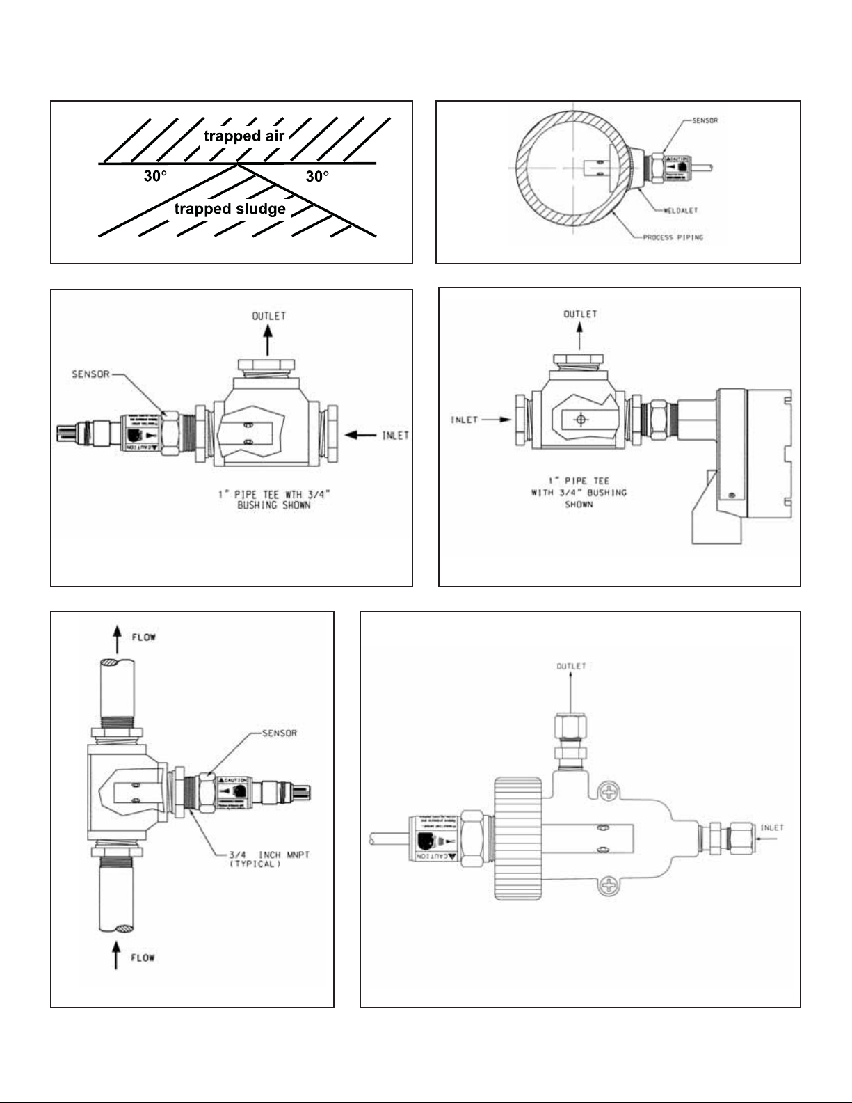
Keep 1/4 in. (6 mm) clearance between electrodes and piping. The electrodes must be completely submerged in the
process liquid, i.e., to the level of the threaded connection. See Figures 1 - 6 for recommended orientation and installation. Models 400 and 400VP sensors with 0.1 and 1.0/cm cell constants can be installed in 3/4-inch pipe tees. All Model
400 and 400VP sensors can be installed in 1-inch tees with a 3/4-inch bushing.
If the sensor is installed in a pipe tee or flow cell with the sample draining to open atmosphere, bubbles may accumulate
on the electrodes. Trapped bubbles will cause errors. As bubbles accumulate, the conductivity reading normally drifts
down. In the plastic flow cell, bubbles are readily visible. To control bubble formation, apply a small amount of back pressure to the flow cell or pipe tee.
-60: 32-392°F (0-200°C)
(requires sensor-mounted
junction box)
The wetted sensor materials may not be compatible
with process com position and operating conditions.
Application compat ibility is entirely the
responsi-
bility of the user.
CAUTION
SENSOR/PROCESS
APPLICATION COMPATIBILITY
WARNING
Before removing the sensor, be absolutely certain
that the process pressure is reduced to 0 psig and
the process temperature is lowered to a safe level!
WARNING
Model 400 and 400 VP
ENDURANCE™Conductivity Sensors
Page 2
2
MODEL 400 and 400VP WIRING
FIGURE 3. Insertion in a Pipe Tee
FIGURE 4. Insertion in a Pipe Tee
FIGURE 5. Insertion in a Pipe Tee
FIGURE 6. Insertion in a Flow Cell (PN 24091-02)
FIGURE 1. Sensor Orientation
FIGURE 2. Direct Insertion in a Pipe
°
°
Page 3
3
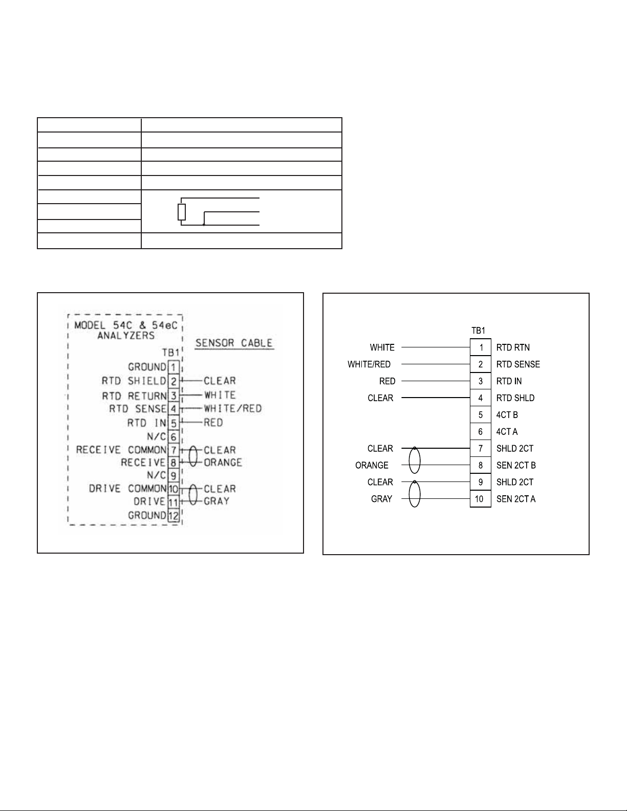
WIRING
MODEL 400 and 400VP WIRING
WIRE COLOR AND CONNECTIONS IN SENSOR
COLOR FUNCTION
Gray Connects to outer electrode
Clear Coaxial shield for gray wire
Orange Connects to inner electrode
Clear Coaxial shield for orange wire
Red
White with red stripe
White
Clear Shield for all RTD lead wires
RTD
RTD in
RTD sense
RTD return
FIGURE 7. Model 54eC Wiring
FIGURE 8. Model 56 and 1056 Wiring
WIRING DIAGRAMS
Page 4

4
FIGURE 12. Model 5081C Wiring
MODEL 400 and 400VP WIRING
RCV B
RCV A
RSHLD
DRVB
RTN
SENSE
RTD IN
SHLD
CLEAR
WHITE/RED
RED
DRVA
DSHLD
WHITE
CLEAR
GRAY
ORANGE
CLEAR
TB1TB2
FIGURE 9. Model 1066 Wiring
FIGURE 13. Model 6081-C Wiring
FIGURE 10. Model Xmt-C-10 Wiring (Panel)
FIGURE 11. Model Xmt-C-11 Wiring (Pipe or Wall)
Page 5

5
MODEL 400 and 400VP WIRING
WIRING THROUGH A JUNCTION BOX
Model 400-60 sensors have a junction box mounted on the end of the sensor. See Figure 14 for wiring instructions.
If wiring connections are made through a remote junction box (PN 23550-00), wire point-to-point. Use cable 23747-00
(factory-terminated) or 9200275 (raw cable).
FIGURE 14. Sensor-Mounted Junction Box Wiring
NOTES:
1. THE GRAY SENSOR WIRE IS CONNECTED TO THE JUNCTION BOX,
WHICH MAKES ELECTRICAL CONTACT WITH THE OUTER ELECTRODE.
2. TERMINALS IN JUNCTION BOX ARE NOT NUMBERED. REFER TO
ANALYZER WIRING DIAGRAM FOR CONNECTIONS AT ANALYZER.
FIGURE 15. VP pin-out (viewed from connector end of
sensor, looking down)
PIN OUT DIAGRAM FOR 400VP
CLEANING THE SENSOR
Use a warm detergent solution and a soft brush or pipe cleaner to remove oil and scale. Isopropyl alcohol (rubbing
alcohol) can also be used to remove oily films. Avoid using strong mineral acids to clean conductivity sensors.
CALIBRATION
ENDURANCE conductivity sensors are calibrated at the factory and do not need calibration when first placed in
service. Simply enter the cell constant printed on the label into the analyzer.
After a period of service, the sensor may require calibration. The sensor can be calibrated against a solution having
known conductivity or against a referee meter and sensor. If using a standard solution, choose one having conductivity in the recommended operating for the sensor cell constant. Refer to the analyzer manual or product data sheet
for recommended ranges. Do not use standard solutions having conductivity less than about 100 uS/cm. They are
susceptible to contamination by atmospheric carbon dioxide, which can alter the conductivity by a variable amount
as great as 1.2 uS/cm (at 25°C). Because 0.01/cm sensors must be calibrated in low conductivity solutions, they are
best calibrated against a referee meter and sensor in a closed system.
For more information about calibrating contacting conductivity sensors, refer to application sheet ADS 43-024, available
on the Rosemount Analytical website.
Page 6
6
TROUBLESHOOTING
PROBLEM PROBABLE CAUSE SOLUTION
Off-scale reading Wiring is wrong. Verify wiring.
Temperature element is open or shorted. Check temperature element for open or
short circuits. See Figure 16.
Sensor is not in process stream. Be sure sensor is completely submerged in
process stream.
Variopol cable is not properly seated. Loosen connector and reseat.
Sensor has failed. Perform isolation checks. See Figure 17.
Noisy reading Sensor is improperly installed in process Be sure sensor is completely submerged
stream. in process stream.
Variopol cable is not properly seated. Loosen connector and reseat.
Reading seems wrong (lower Bubbles trapped in sensor. Be sure sensor is properly oriented in
or higher than expected) pipe or flow cell. See Figure 1.
Apply back pressure to flow cell.
Wrong temperature correction algorithm. Check that temperature correction is
appropriate for the sample. See analyzer
manual for more information.
Wrong cell constant. Verify that the correct cell constant has
been entered in the analyzer and that the
cell constant is appropriate for the conductivity
of the sample. See analyzer manual.
Sluggish response Electrodes are fouled. Clean electrodes.
Sensor is installed in dead area in piping. Move sensor to a location more
representative of the process liquid.
MODEL 400 and 400VP WIRING
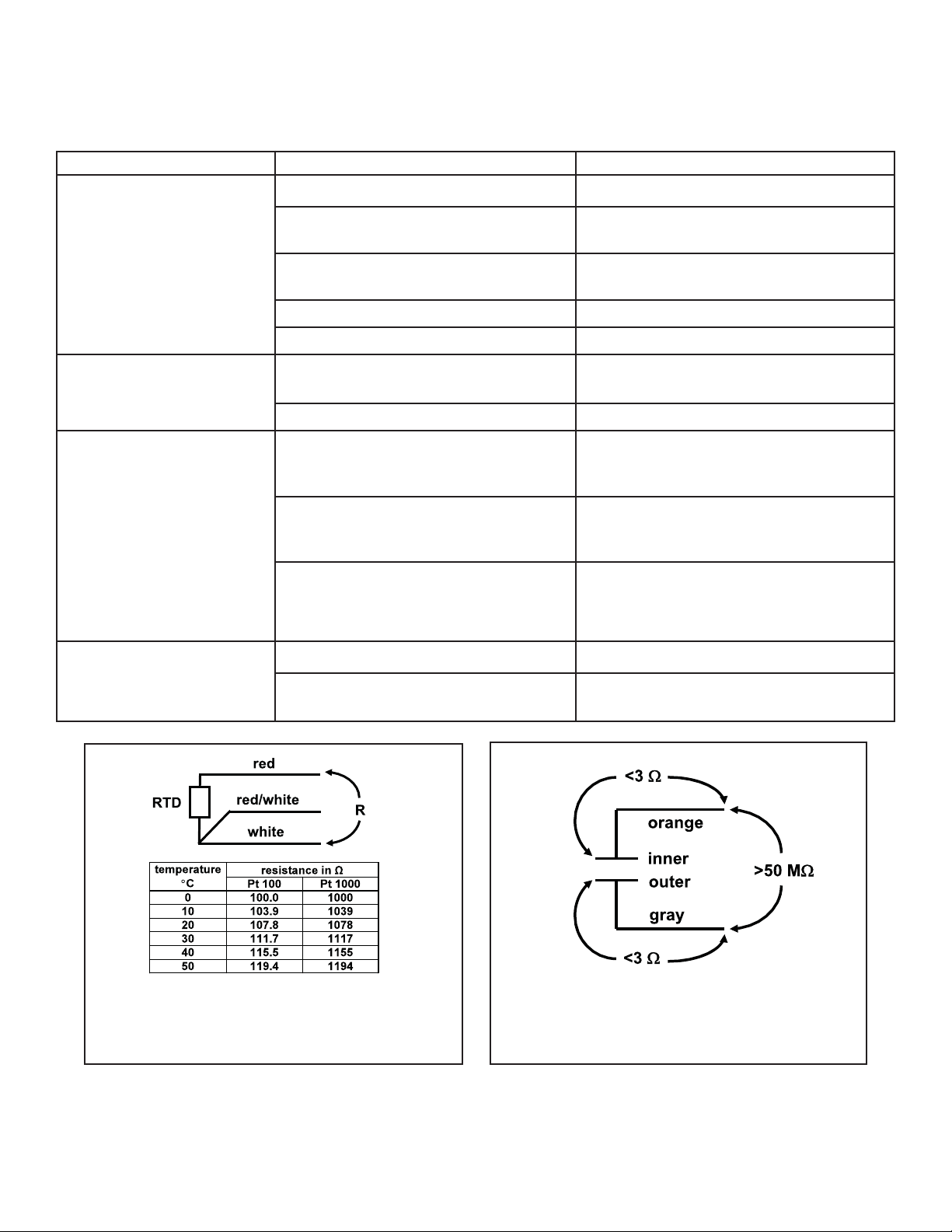
FIGURE 16. Checking Temperature Element
Disconnect leads and measure resistance shown. The measured resistance should be close to the value in the table.
FIGURE 17. Checking Continuity and Leakage
Disconnect electrode leads and measure resistance and
continuity as shown. Sensor must be dry when checking
resistance between electrode leads.
Page 7

7
NOTES
Page 8

Credit Cards for U.S. Purchases Only.
The right people,
the right answers,
right now.
ON-LINE ORDERING NOW AVAILABLE ON OUR WEB SITE
http://www.raihome.com
Specifications subject to change without notice.
Emerson Process Management
2400 Barranca Parkway
Irvine, CA 92606 USA
Tel: (949) 757-8500
Fax: (949) 474-7250
http://www.raihome.com
© Rosemount Analytical Inc. 2010
8
 Loading...