

Specifications and Main Features
- It is a VILTER MultiCylinder Compressor 400 VMC series.
- Of said above model/series, the operating voltage is 400V.
- Positive Displacement, specifically developed for superheated vapor pumping, is the type of the compressor.
- The range of parameters:
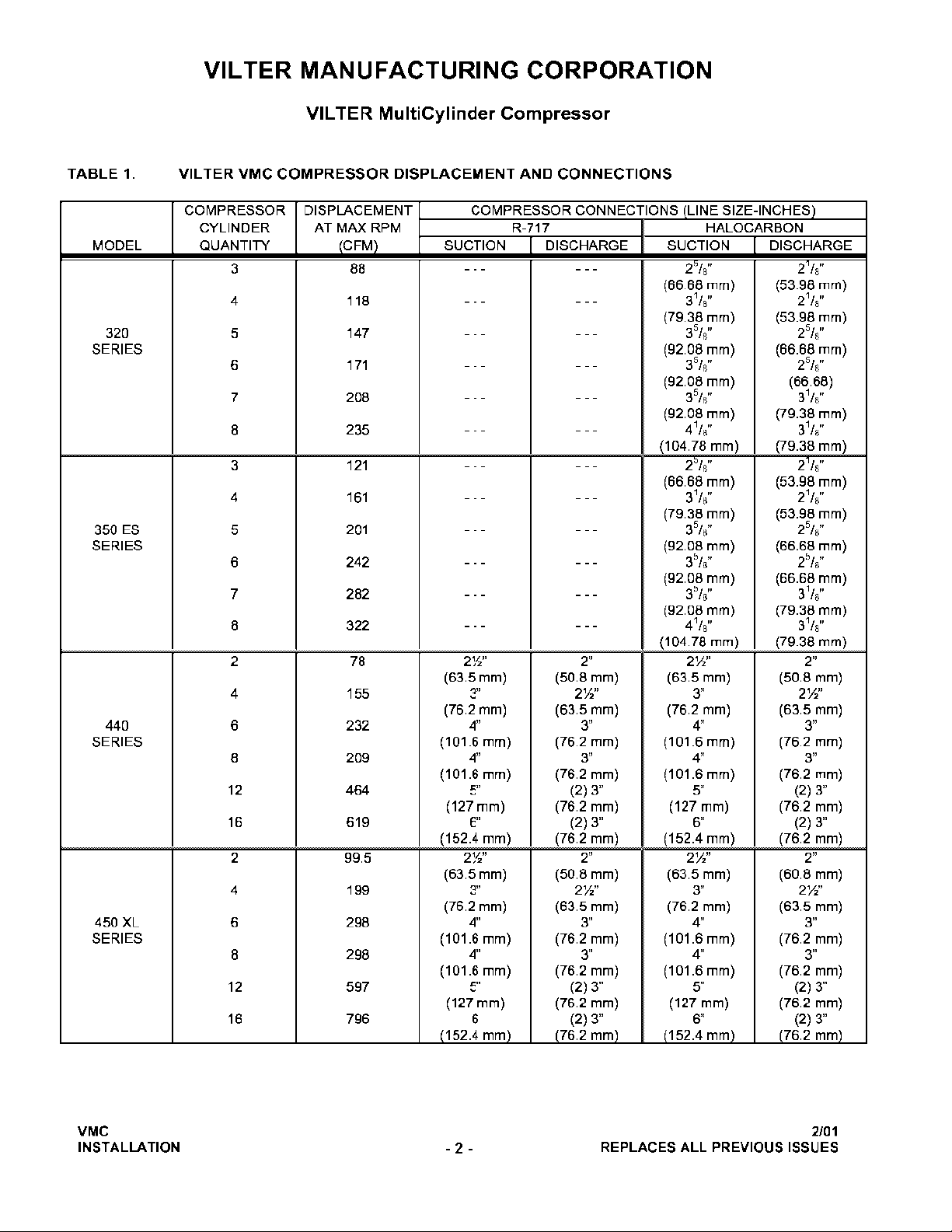
- 88 CFM is the maximum for 3 cylinders.
- 418 CFM is the maximum for 4 cylinders.
- 147 CFM is the maximum for 5 cylinders.
- 171 CFM is the maximum for 6 cylinders.
- 208 CFM is the maximum for 7 cylinders.
- 235 CFM is the maximum for 8 cylinders.
- And further than the above mentioned models with several other capacities
- Sizes of Connection:
- Connection of CIRCULATING water inlet and outlet pipe varies in kind, such as 3’’ up to 4’’ connection for large models.
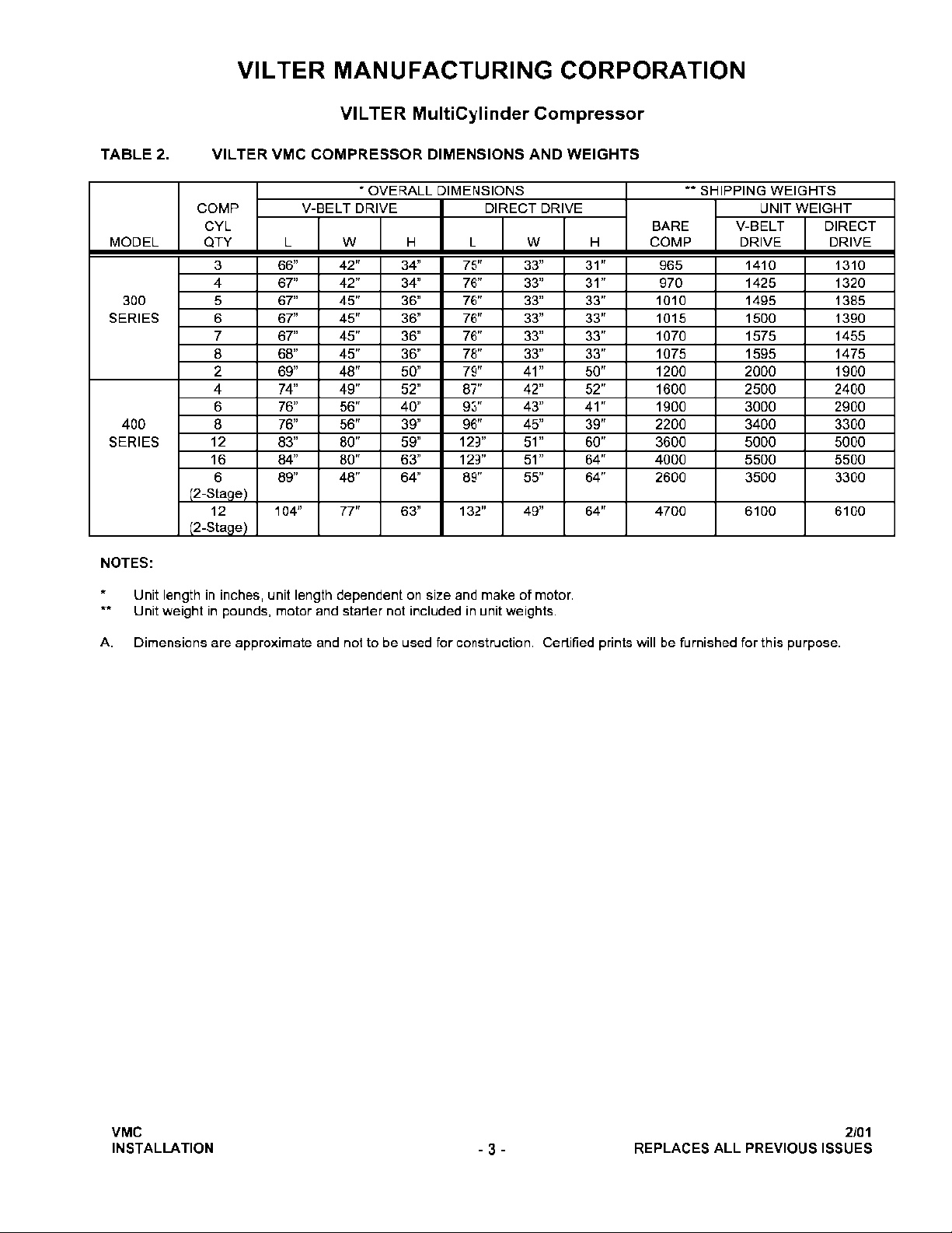
- Weight and Size:
- Sizes are provided in the installation section based on model.
- Depending on the model and configuration it weighs between 965 to 4000 lbs .
- Type of oil system:
- It allows to heat the crankcase.
- It assists in oil cooling for regulating temperature.
- Safety Devices: Local safety regulations should be followed; It incorporates the above appliances and the electric equipment's safety controls.
- Maintenance Recommendations: In order to allow the model to operate as required, a daily, weekly, monthly and yearly schedule for servicing is set.
Frequently Asked Questions
- Which vapor can the VILTER compressor magnitude withstand?
- The magnitude of the compressor can only withstand vapor which is superheated.
- What is the Capacity of the Compressor?
- The compressor’s maximum capacity depends on the model with the larger configurations rated for a maximum of 619 CFM.
- What electrical specifications are necessary?
- The compressor needs an electrical power supply of 400 volts.
- Does the compressor come with any safety features?
- Yes, Safety devices are designed especially for the locality standards which includes electrical interlocks and full guards for moving parts.
- What Kind of oil Should be Used to the Compressor?
- Vilter recommends using only Vilter-approved lubricants for the VMC Compressors in order to protect warranty coverage.
- How often should a Maintenance be Required?
- Various checks should be done regularly on a daily, weekly, monthly and yearly basis alongside a lubricating program and systematic maintenance for the latter is recommended.
- Is It Possible For the Outdoor Stored VMC to function Outside?
- Although Yes, it can be stored outdoors, but it needs to be in an area with sufficient drainage which helps avoid accumulation of water and also requiring application of suitable rust inhibitors on the metal surfaces.
- Is There a Manual Which Explains the Installation Process?
- There is a manual which roughly outlines the parameters on devoiring details while following the parameters closely is greatly essential.
User Manual
Page 1
400 VMC series compressor
Operation and service manual
Page 2

Page 3

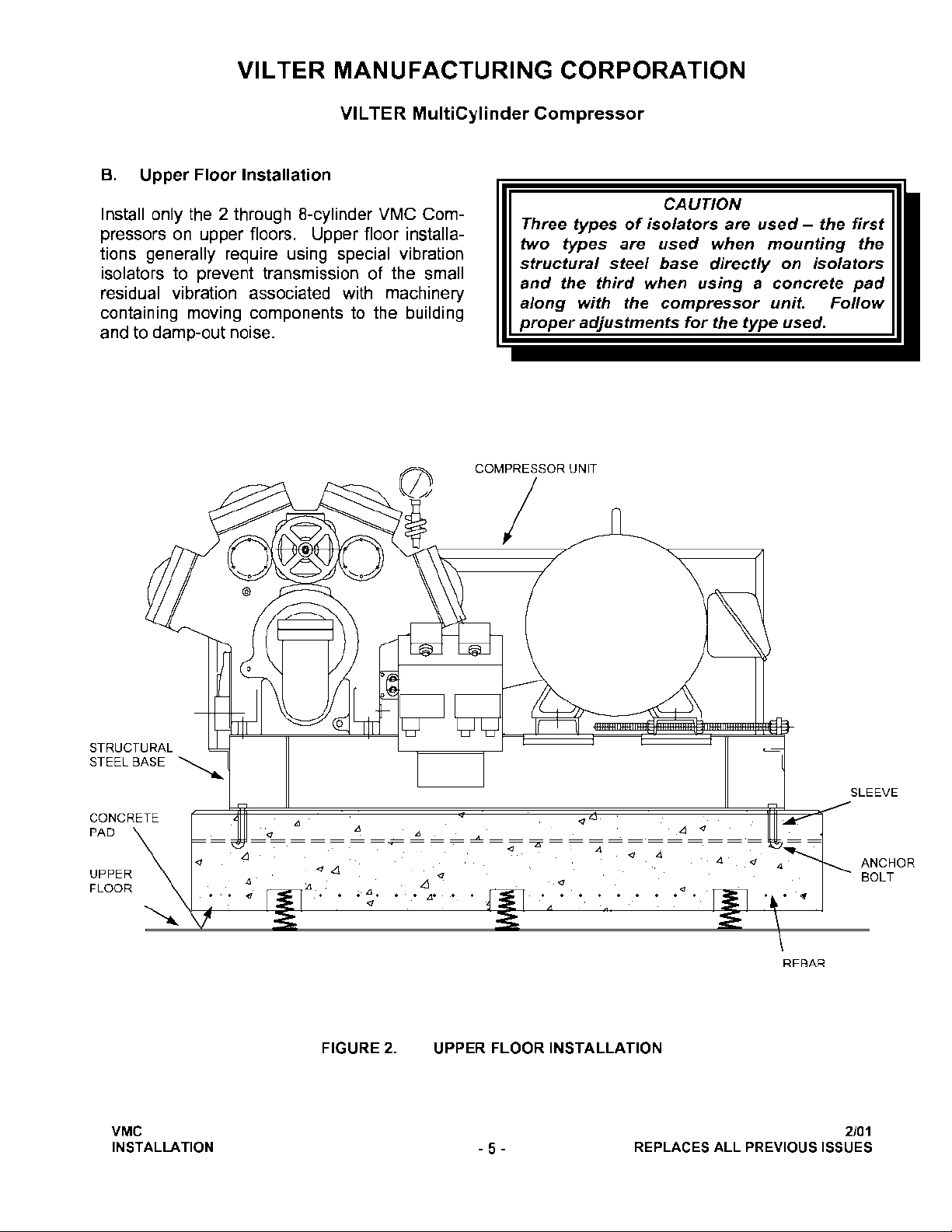
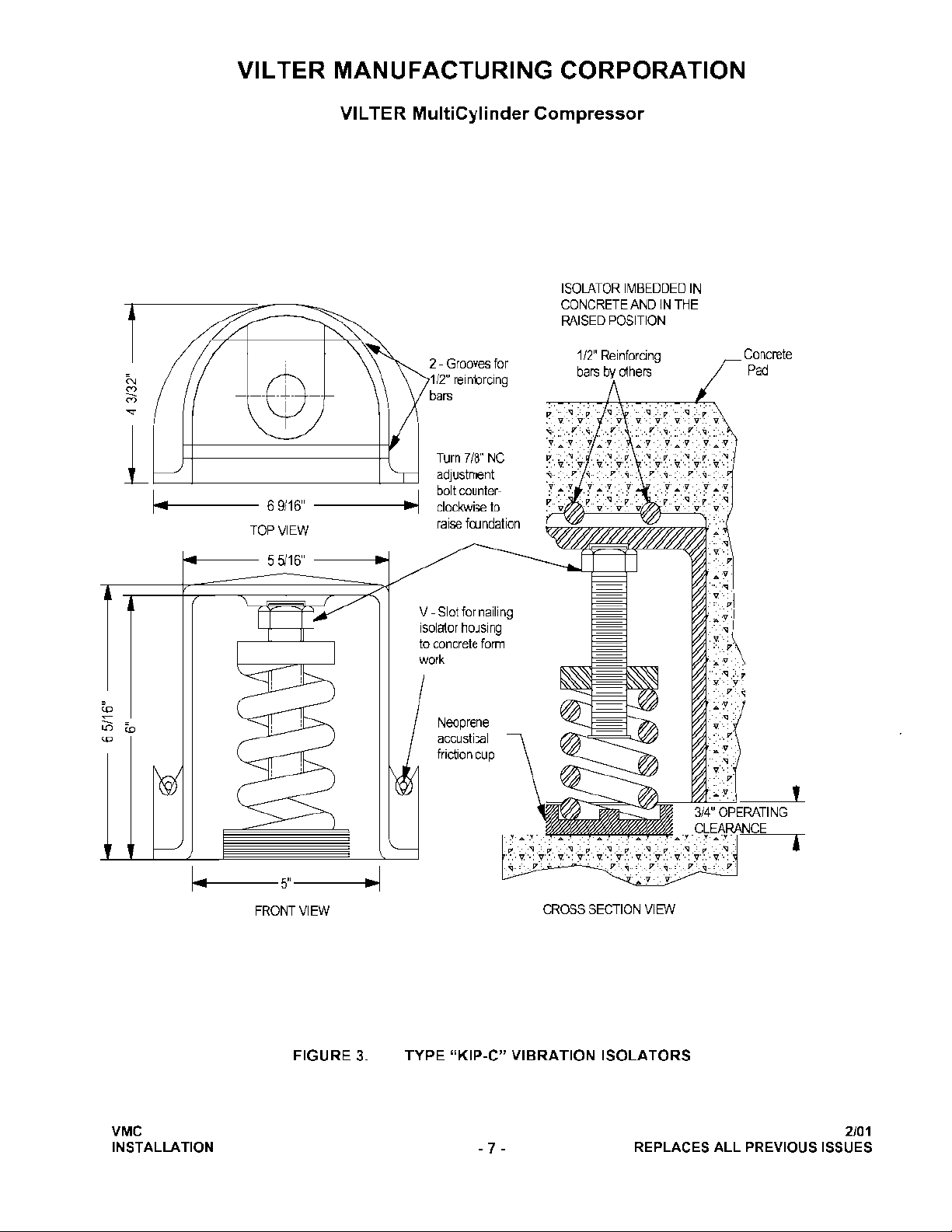
VILTER MANUFACTURING CORPORATION
VILTER Multicylinder Compressor
OPERATING INSTRUCTION MANUAL
400 SERIES COMPRESSORS
READ CAREFULLY BEFORE INSTALLING AND STARTING YOUR COMPRESSOR.
The entire manual should be reviewed before attempting to install, service or repair the compressor.
A refrigeration compressor is a positive displacement machine. It is designed to pump superheated
vapor. The compressor must not be subjected to liquid carry over. Care must be exercised in properly
designing and maintaining the system to prevent conditions that could lead to liquid carry over. Vilter
Manufacturing Corporation is not responsible for the system or the controls needed to prevent liquid
carry over and as such Vilter Manufacturing Corporation cannot warrant equipment damaged by improperly protected or operating systems.
Vilter screw compressor components are thoroughly inspected at the factory, assuring the shipment of a
mechanically perfect piece of equipment. Damage can occur in shipment, however. For this reason, the
units should be thoroughly inspected upon arrival. Any damage noted should be reported immediately to
the Transportation Company. This way , an authorized agent can examine the unit, determine the extent
of damage and take necessary steps to rectify the claim with no serious or costly delays. At the same
time, the local Vilter representative or the home office should be notified of any claim made.
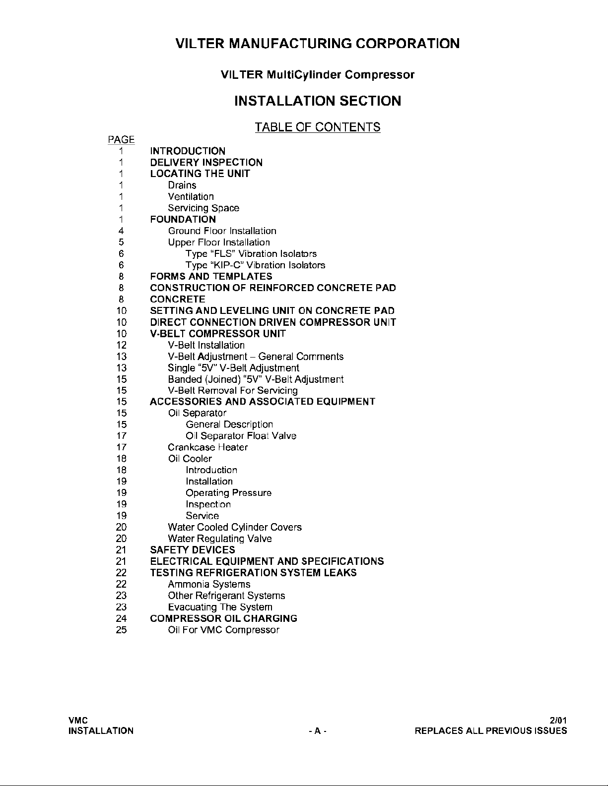
TABLE OF CONTENTS
This manual consists of the following sections:
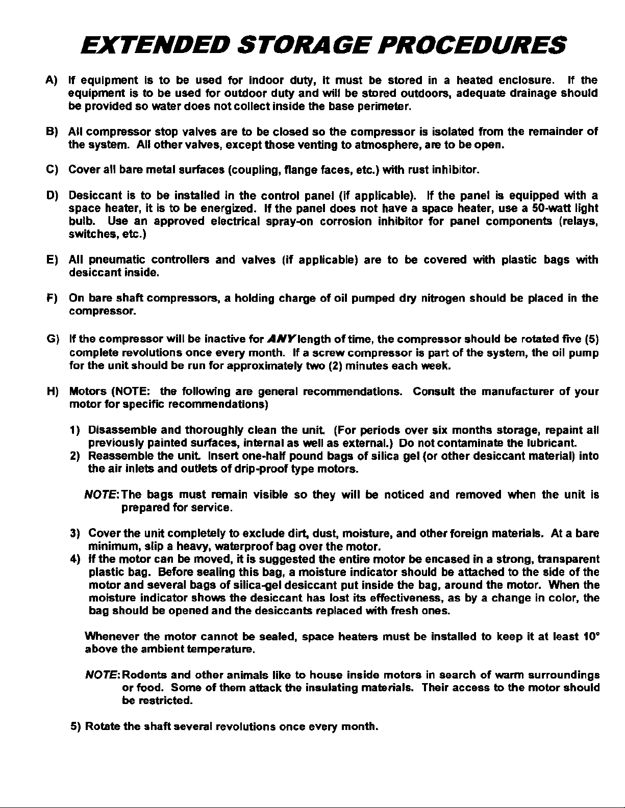
EXTENDED STORAGE PROCEDURES
INSTALLATION INSTRUCTION SECTION
This section should be read thoroughly before attempting to install a VMC
Compressor. IMPORTANT: Local codes and ordinances should be
checked beforehand so that violations do not occur, especially concerning
devices for control and safety.
COMPRESSOR OPERATION SECTION
COMPRESSOR SERVICE SECTION
COMPRESSOR REPLACEMENT PARTS SECTION
Section 100R
Section 102R
Section 105R
Section 105X
Page 4
Page 5
Page 6
Page 7
Page 8
Page 9
Page 10
Page 11
Page 12
Page 13
Page 14
Page 15
Page 16
Page 17
Page 18
Page 19
Page 20
Page 21
Page 22
Page 23
Page 24
Page 25
Page 26
Page 27
Page 28
Page 29
Page 30
Page 31

Page 32

Page 33

Page 34

Page 35

Page 36

Page 37

Page 38

Page 39

Page 40

Page 41

Page 42

Page 43

Page 44

Page 45

Page 46

Page 47

Page 48

Page 49

Vilter Stop/Check-Valve General Information
AUTO
In the “Auto Position”, the stop valve is operating as a check valve,
allowing flow in the directions of the arrows.
To set the valve to the automatic position, fully close the valve, and
turn the stem out as indicated by the chart below.
CLOSED
In the manually “Closed Postion”, the stop check is operating as a
convientional stop valve, not allowing flow in either direction.
OPEN
In the manually ” Open Position”, with the valve stem fully back seated,
the valve disc is lifted slightly, allowing flow in either direction.
Page 50

Verify the location of Spring and note the direction of the Vilter name
Installation: The new design will apply only to the 2” thru 4” stop valves.
Retrofitting a field installation will require replacing the bonnet
assembly.
The bonnet must be installed with the spring towards the bottom (see
illustrations above). The drill fixture is designed so that the hole for the spring
will always be drilled on the opposite side from the cast in Vilter name on the
bonnet. From the outside of the valve, the casting numbers must always be
towards the top of the valve.
Page 51

Page 52

Page 53

Page 54

Page 55

Page 56

Page 57

Page 58

Page 59

Page 60

Page 61

Page 62

Page 63

Page 64

Page 65

Page 66

Page 67

Page 68

Page 69

Page 70

Page 71

Page 72

Page 73

Page 74

Page 75

Page 76

Page 77

Page 78

Page 79

Page 80

Page 81

Page 82

Page 83

Page 84

Page 85

Page 86

Page 87

P28 and P128 Series Lube Oil Controls
with Built-in Time Delay Relay
The P28 and P128 Series Lube Oil Controls provide
dependable and economical oil pressure cut-out for
pressure-lubricated refrigeration compressors. The
field-adjustable pressure differential of these controls
provides compressor operation according to the
manufacturer’s specifications. The P28 and P128
controls operate by measuring the net lube oil pressure
and de-energizing the compressor if the pressure falls
below the differential setpoint.
Manual or automatic reset models are available with
factory set and sealed time delays of 30, 45, 60, 90,
or 120 seconds (all time delays may not be available
on all models). The P128 is the same control as the
P28 but with 1/4 inch male flare pressure connections.
Master Catalog 125
Pressure Controls Section P
Product/Technical Bulletin P28
Issue Date 0498
Figure 1: P128AA
Features and Benefits
Built-in Time Delay Relay
with Ambient Compensation
Trip-free Manual Reset Provides manual reset that cannot be overridden
Replaceable Time Delay
Relay Assembly
Available with Runlight and
Alarm Terminals
Minimizes timing fluctuations due to temperature
variations
by pressing and holding the reset button
Allows easy field replacement of the time delay
relay and terminal board
Allows the control to be wired for normal oil
pressure runlight signals and shutdown alarm
circuits for remote monitoring of oil pressure
status
© 1998 Johnson Controls, Inc.
Part No. 24-7664-605, Rev. A
Code No. LIT-125420
1
Page 88

ntroduction
I
!
WARNING: Personal injury hazard. All
P28 and P128 controls are
designed as lubrication
protection controls. Failure of
the P28 or P128 could allow
the refrigeration compressor
to be damaged in a way that
may not be apparent upon
visual inspection. Follow
proper procedures and the
compressor manufacturer’s
instructions, as well as any
warning signs on or around
the equipment, when
discharging and
disassembling the
compressor.
Environmental damage
hazard. If leakage of sensed
media (such as refrigerant or
oil) can be harmful to the
environment, or hazardous in
any way, user must provide
for proper containment.
The P28 and P128 controls measure the net oil
pressure available to circulate oil throughout a
pressure-lubricated refrigeration system. The net oil
pressure is the difference between the oil pressure at
the pump discharge and the refrigerant pressure in
the compressor crankcase.
Example: If the oil pressure pump discharge reading
is 90 psi (621 kPa) and the crankcase
pressure is 70 psi (483 kPa), the net oil
pressure is 20 psi (138 kPa).
The P28 and P128 have a built-in time delay relay.
This relay allows the oil pressure to build up for the
time delay period before the compressor trips. This
also prevents nuisance lockouts due to intermittent
loss of oil pressure. The time delay relay is a
“trip free” device. The manual reset cannot be
overridden by pressing and holding the reset button.
Manual reset models are available with time delays
of 30, 45, 60, 90, or 120 seconds. Automatic reset
models are available with a 90-second time delay.
The time delay relay is compensated to minimize the
effect of ambient temperature variations. However,
the time delay relay will be affected by voltage
variations.
Dimensions
Figure 2: P28 or P128 Dimensions (in./mm)
peration
O
When the compressor starts, the timer is energized
because the ne t oil pressure of the system is zero.
During normal operation, the net oil pressure should
build up to the pressure switch’s cut-out setting
(scale setting) plus the switch differential (3 to 5 psi
[21 to 34 kPa]) within the required time delay,
causing the time delay relay to de-energize.
If the net oil pressure does not rise to the cut-out
pressure setting plus the switch differential within the
required time delay, the time delay relay trips and
stops the compressor.
If the net oil pressure drops below the cut-out
pressure setting during the compressor’s run cycle,
the time delay relay energizes. If the net oil pressure
returns within the time delay, the time delay relay deenergizes and the compressor continues to operate
normally. If the net oil pressure does not return
within the time delay, the control shuts down and
locks out the compressor.
2 P—P28 and P128 Series Lube Oil Controls with Built-in Time Delay Relay Product/Technical Bulletin
Page 89

Example: Net oil pressure (oil pump pressure minus
crankcase pressure) required to the
bearings is 9 psi (62 kPa). The control
scale setting should be 9 psi (62 kPa).
The switch differential is 5 psi (34 kPa).
Upon initial start of the compressor, the
time delay relay energizes. If the net oil
pressure does not build up to 14 psi
(97 kPa), or the scale setting (9 psi) plus
the switch differential (5 psi), during the
time delay, the control breaks the circuit to
the compressor. If the pressure of 14 psi
(97 kPa) is reached during the time delay,
the time delay relay de-energizes and the
compressor continues to operate normally.
nstallation
I
Mounting
Pressure Connections
!
CAUTION: Equipment damage hazard.
●
Avoid sharp bends or kinks in the
capillary or tubing to avoid damage to
the capillary.
●
Coil and secure excess capillary or
tubing. Because harmonic vibration
can break the capillary or tubing, some
slack must be provided.
●
Do not allow the capillary or tubing to
rub against metal surfaces where
friction can cause damage.
●
When using a control with
1/4 in. / 6.4 mm tubing, a pulsation
damper must be used. Pulsation can
cause excessive wear and damage
the control.
!
CAUTION: Equipment damage hazard.
●
A P28AN or P28DN control used for
ammonia service must be mounted
separately from the electrical cabinet.
An ammonia leak could damage the
electrical circuitry.
●
Do not use Johnson Controls/Penn
Ecosafe® hose tubing in applications
with ammonia or other corrosive
refrigerants. Corrosion could cause
tube breakage and refrigerant
leakage.
●
Use only the mounting screws
supplied with the control. Damage to
internal components may occur if
other screws are used.
The P28 and P128 controls are not position sensitive
and can be mounted in any position.
Use the two mounting screw holes located on the
back of the control case to mount the control directly
to a wall or panel board. Mount the control so that
the pressure connections on the bellows are above
the crankcase liquid level of the equipment being
controlled.
Note: When mounting the control to a
compressor is required, a mounting bracket
(Part No. 271-51) is available.
1. Purge all tubing and lines before connecting the
pressure control.
2. Connect the oil pressure line pump discharge to
the pressure connector labeled “OIL.”
3. Connect the crankcase pressure line to the
pressure connector labeled “LOW.”
4. Coil and secure excess capillary or tubing to
avoid vibration.
Wiring
!
WARNING:
●
Make all wiring connections using copper
conductors only.
●
Wire in accordance with National Electric Code
and local regulations. For maximum electrical
rating of the control, see the label inside the
control cover.
●
Use the terminal screws furnished (8-32 x 1/4 in.
binder head). Substitution of other screws may
cause faulty connections.
Shock hazard.
Disconnect all
power supplies before making
wiring connections to avoid
electrical shock or damage to
the equipment.
P—P28 and P128 Series Lube Oil Controls with Built-in Time Delay Relay Product/Technical Bulletin 3
Page 90

See Figures 3 through 10 for typical wiring diagrams
y
y
y
g
y
g
g
y
g
or refer to the compressor manufacturer’s
specifications.
When the P28 or P128 control is supplied with a
Terminal 3, it may be wired to operate a runlight for
indicating when there is sufficient net oil pressure.
When the control is supplied with a Terminal A, it can
be wired to operate a shutdown alarm or signal for
indicating when the compressor has tripped.
For applications using a 208V control circuit, it is
suggested that one leg of the 208V circuit and a
neutral or ground wire be used as a 120V source to
power the time delay relay.
When a P28 or P128 is installed on a 440 or 550
VAC system, use an external step-down transformer
to provide either 120 or 240V to the pilot and time
delay relay circuits. The transformer must be of
sufficient volt ampere capacity to operate the motor
starter and the time delay relay. Table 1 presents
the power requirements for the P28 or P128 time
delay relay. Table 2 presents the electrical ratings.
Table 1: Electrical Power Required for
Time Delay Relay
Voltage
Timing in Se conds 12, 24, or 120V 240V
30, 45, 60, 90, or 120
Table 2: Electrical Ratings--Pilot Duty
Time Delay Relay
Circuit
120/240 VAC 750 VA, 120/240 VAC 10W Tungsten, 120/240 VAC 10 Ampere, 120 VAC
24 VAC/VDC
12 VAC/VDC
* Must be the same voltage as the pilot circuit.
** Must be the same voltage as the time delay relay circuit.
Low
Pilot Circuit Alarm Circuit* Crankcase Heater**
(Terminal 1)
5 Ampere, 240 VAC
125 VA, 24 VAC
57.5 VA, 24 VDC
PC
2
Oil
120/240 M odels
240
3
1
PC
TD
1
2
2
H
120
DR
L
TD
M
A
125 VA, 24 VAC
57.5 VA, 24 VDC
1
Low
Oil
Low Volta
3
1
PC
PC
2
1
2
H
*12 volt also available.
e Models
TD
2
24*
L
TD
M
A
15 VA 30 VA
Runlight**
(Terminal 3)
10W Tungsten
-- 10W Tungsten
1
-
Pressure actuated contacts. Open on increase in pressure difference between oil and low pressure conntectors. Makes
PC
1
and breaks tim e dela
-
Contacts close simultaneousl
PC
2
-
Time dela
TD
1
is not established or maintained.
-
TD
Contacts close simultaneousl
2
DR--Volta
-
H
H eater f o r time dela
Connect Terminals L and M as a sin
Connect Terminals 2 and 240 or 120 to ener
relay. Conta c t s o pe n afte r time d e l ay interval if pressure dfference between oil and low pressure connectors
e dropping resistor used in dual voltage models.
heater circuit.
when PC contacts open (runlight circuit).
when TD contacts open (alarm circuit).
relay.
le p ole s witch.
1
1
ize circuit only when motor starter is closed.
Figure 3: P28 or P128 Internal Wiring Circuit, Showing Alarm Circuit and Runlight Terminals
4 P—P28 and P128 Series Lube Oil Controls with Built-in Time Delay Relay Product/Technical Bulletin
Page 91

y
g
Crankcase
g
g
y
y
g
g
g
y
g
Heater
When Used*
Add itional c ont ro l s in th is lin e onl
Operatin
Control
240
1
L
2
M
A
120
P28 or P 12 8
240V 3-phase
.
L
1L2L3
T1T
Motor
2T3
Ground
120 or 24 0V
Suppl
Hot
Crankcase
Heater
When Used*
Alarm
if Used
Runli
if Used
240
3
L
1
M
2
*
A
120
P28 or P12 8
ht
240 or
120V
Operatin
Control
Any Voltage
C
2
L1L2L
C
4
C
3
T
1T2T3
Motor
Additional controls
in this line o nl
3
.
*Crankc ase heater cannot be cycled with this hookup. See Figure 5.
Figure 4: P28 or P128 Used on a 240V System with
240V Magnetic Starter Coil
Add itional c ont ro l s in th is lin e only.
Crankcase
Heater
When Used*
Runli
if Used
ht
Operatin
Control
240
3
L
1
2
*
Alarm
if Used
M
A
120
P28 or P 12 8
*When crankcase heater is used, disconnect jumper fr o m 2 to M
and reconnect from 2 to L.
240V 3-phase
L1L2L
T
1T2T3
Motor
3
Figure 5: P28 or P128 Wired for 3-wire Control
(Jumper between 2 and M [or L] must be field
installed.)
*Wh e n crank cas e heater is use d, disconnec t jump er from 2 to M
and reconnect from 2 to L.
Figure 6: P28 or P128 Where Separate Supply is
Provided for Control Circuit (Jumper between
2 and M [or L] must be field installed.)
440V
3-phase
Crankcase
Heater
When Used*
240V 440V
Runli
ht
if Used
C
C
L1L2L
2
3
240
3
T
1T2T3
Motor
Additional controls
in this line onl
.
Alarm
if Used
L
1
M
2
*
A
120
P28 or P 12 8
Operatin
Control
*When crankcase heater is used, disconnect jumper 2 to M
and reco nn ect 2 to L . Also, m ake su re that control circuit
transformer has sufficient output for addition al load.
Figure 7: P28 or P128 Wired for 440V Supply
and 240V Magnetic Start Coil (Also for 550V
Using Proper Transformer) (Jumper between
2 and M [or L] must be field installed.)
3
P—P28 and P128 Series Lube Oil Controls with Built-in Time Delay Relay Product/Technical Bulletin 5
Page 92

240V
g
y
g
y
y
g
3-phase
L1L2L
2
3
Crankcase
Heater
When Used*
Runli
if Used
ht
Start
C
C
Stop
240
3
Alarm
if Used
L
1
2
*
M
A
T1T2T
Motor
Additional controls
120
in this line o nl
.
P28 or P12 8
*When crankcase heater is used, disconnect jumper from 2 to M
and reconnect 2 to L.
Compressor
3
Low
Oil
3
P74AA
Motor
Low
P28/P128
Oil
Junction Box
Operatin
Control
1
240
L
2
M
240 V
L
1
T
1
L
2
L
3
T
2
T
3
Note:This system would provide shutdown on low
lube oil pressure in either of two com pres sors
operated b
the common motor.
Figure 10: P28 or P128 and P74AA Wired for an
Oil Pressure Control System Where One Motor
Operates Two Compressors
Figure 8: P28 or P128 Where Manual “Start-Stop”
Pushbutton Station is Used (Jumper between
2 and M [or L] must be field installed.)
240V
3-phase
L
1L2L3
T1T2T
Motor
.
3
Alarm
if Used
3
L
1
2
M
A
24*
P28 or P 12 8
Transform er
Starter Coil
Operatin
Control
Additional controls
in this line onl
*12 volt also available.
Figure 9: P28 or P128 Where 24V Control Circuit
Power is from a Step-down Transformer (Jumper
between 2 and M must be field installed.)
Adjustments
The P28 and P128 controls are shipped with a cut-out
pressure differential of 9 psi (62 kPa). However, the
controls can be adjusted according to the compressor
manufacturer’s specifications.
Note: When the controls are shipped as an
accessory to the compressor unit, time delay
and cut-out pressure are set to manufacturer’s
specifications. Replacement controls should
duplicate the manufacturer’s specifications.
!
CAUTION: Equipment damage hazard.
To avoid damage to the
compressor, obtain the
compressor manufacturer’s net
oil bearing pressure
specifications as soon as
possible. If necessary, reset the
cut-out pressure difference to the
manufacturer’s specifications.
When the manufacturer’s specifications are not known,
proceed as follows to set the cut-out pressure
differential:
1. With the compressor running, read the oil pressure
and the crankcase pressure.
2. Subtract the crankcase pressure reading from the
oil pressure pump discharge reading. This is the
net oil pressure to the bearings.
6 P—P28 and P128 Series Lube Oil Controls with Built-in Time Delay Relay Product/Technical Bulletin
Page 93

3. Set the cut-out pointer 6 to 8 psi (41 to 55 kPa)
below the established running net oil pressure with
the Adjusting Disk using a standard screwdriver.
3. Apply power to start the compressor. The time
delay relay should trip after the time interval and
stop the compressor.
To increase the cut-out pressure, turn the
Adjusting Disk counterclockwise. To decrease,
turn clockwise.
To raise the pressure differential, turn the
Adjusting Disk (see Figure 2) to the left when
viewing the front of the control. Turn the adjusting
disk to the right to lower the pressure differential.
est for Shutdown
T
Immediately after installing, and at regular intervals
thereafter, the time delay relay should be tested to
verify that all circuits are operating correctly.
!
WARNING: Shock hazard. Disconnect
power from the control before
testing for shutdown to avoid
electrical shock or damage to
the equipment.
To test for shutdown:
1. Remove power from the control and remove the
control cover.
2. Connect a jumper between Terminals 1 and 2.
See Figure 3 for terminal locations.
4. Remove power from the control and remove the
jumper between Terminals 1 and 2.
5. Replace the cover on the control and apply power.
6. Manually reset the time delay relay if required.
heckout Procedure
C
Before leaving the installation, observe at least
three complete operating cycles to be sure that all
components are functioning correctly.
ungus Proofing
F
Fungus proofing can be supplied at extra cost when
specified. Conforms to government specifications
MIL-V-173A.
epairs and Replacement
R
Field repairs must not be made, except for
replacement of the time delay relay assembly. For a
replacement control or time delay relay assembly,
contact the nearest Johnson Controls representative or
Refrigeration Application Engineering at 414-274-5535.
Note: If the control is mounted on a condensing
unit where air from auxiliary equipment
(blowers or fans) may strike the control,
the control cover should be replaced
before proceeding to Step 3.
Table 3: Replacement Time Delay Relay Assemblies
Part Number Voltage Reset Type Timing in Seconds Alarm Circuit
RLY13A-600R
RLY13A-602R
RLY13A-603R
RLY13A-608R
RLY13A-609R
RLY13A-610R
RLY13A-616R
RLY13A-617R
P—P28 and P128 Series Lube Oil Controls with Built-in Time Delay Relay Product/Technical Bulletin 7
120/240 VAC Manual 60 No
120/240 VAC Manual 90 No
120/240 VAC Manual 90 Yes
120/240 VAC Automatic 90 No
24 VAC/VDC Manual 120 No
120/240 VAC Manual 30 No
120/240 VAC Manual 120 No
120/240 VAC Manual 45 No
Page 94

rdering Information
O
Table 4: Ordering Information
Series Part
Number
P28AA
P128AA
P28AN
P28DA
P28DN
P28GA
P28NA
P28PA
* Style 5 connections are 1/4 in. / 6.4 mm SAE male flare connectors (no capillary tubing). Style 13 connections are 36 in. / 914 mm
capillary tubing and 1/4 in. / 6.4 mm flare nut. Style 15 connections are 1/4 in. / 6.4 mm female National Pipe Thread connectors.
pecifications
S
Power Requirements
Pressure Specifications
Pressure Switch Units
Ambient Operating Conditions
Dimensions (H x W x D)
The performance specifications are nominal and conform to acceptable industry standards. For application at conditions beyond these specifications,
consult the local Johnson Controls Refrigeration Application Engineering at (414) 274-5535. Johnson Controls, Inc. shall not be liable for damages
resulting from misapplication or misuse of its products.
Pressure
Connections*
Style 13, Style 5,
or Style 15
Style 5 Manual Non-corrosive
Style 15 Manual Ammonia 120/240 VAC No No
Style 13 Manual Non-corrosive
Style 15 Manual Ammonia 120/240 VAC Yes Yes
Style 13 Automatic Non-corrosive
Style 13 or Style 5 Manual Non-corrosive
Style 5 Manual Non-corrosive
Product
Material
Mounting
Wiring Terminal
Agency Listings
Shipping Weight
Reset Type Refrigerant Time Delay
Relay Voltage
Manual Non-corrosive
All-range
All-range
All-range
All-range
All-range
All-range
P28 and P128 Series Lube Oil Controls with Built-in Time Delay Relay
See Tables 1 and 2.
Adjustable Cut-out Pressure Difference: 8 to 70 psi (55 to 483 kPa)*
Maximum Differential: 70 psi (483 kPa)
Maximum Working Pressure: 250 psig (1724 kPa) on the high side
Maximum Overpressure: 325 psi (2240 kPa) oil and low side pressure
*The time delay relay is de-energized 3 to 5 psi (21 to 34 kPa) above the cut-out scale setting.
Enclosed Dust-protected Pennswitch
32 to 104°F / 0 to 40°C
Case: 0.062 in. / 1.6 mm Galvanized Steel
Cover: 0.028 in. / 0.7 mm Cold Rolled Steel (plated and painted)
Flat Surface or with a Universal Mounting Bracket (Part No. 271-51)
Large 8-32 x 1/4 in. Binder Head Screws
UL Guide No. SDFY; File SA516**
CSA Class No. 1222 01; File LR948**
*
*Most models. Contact Johnson Controls for a complete listing.
5.66 x 5.32 x 2.09 in. / 144 x 135 x 53 mm
3.0 lb / 1.36 kg
120/240 VAC No No
120/240 VAC No No
120/240 VAC Yes Yes
120/240 VAC No No
24 VAC/VDC No No
24 VAC/VDC No No
Alarm
Terminal
Runlight
Terminal
Controls Group FAN 125
507 E. Michigan Street Master Catalog
P.O. Box 423 Printed in U.S.A.
Milwaukee, WI 53201
8 P—P28 and P128 Series Lube Oil Controls with Built-in Time Delay Relay Product/Technical Bulletin
Page 95

Master Catalog 125
Temperature Controls Section A
Product Bulletin A70, A72
A70, A72 Series Temperature Controls
for Refrigeration and Heating
Issue Date 0996
Applic ation
The A70 single-pole and A72
two-pole controls are supplied in a
wide selection of ranges to meet
most application needs. See
“Temperature Ranges.”
Models may be supplied to open
a circuit on temperature increase
or close a circuit on temperature
increase as required. An A70
single-pole control may optionally
include a separate reverse-acting
auxiliary contact. Models are
available with a SPDT enclosed
Pennswitch.
All Series A70, A72 controls are
designed for use
operating controls. Where an
operating control failure would
result in personal injury and/or
loss of property, it is the
responsibility of the installer to
add devices (safety, limit
controls) or systems (alarm,
supervisory systems) that
protect against, or warn of,
control failure.
only
as
Specifications
Features
•
Long life contact structure with
high contact force right up to
break -- no bounce on make.
•
Make reset models are
“trip-free”.
•
Ranges available to cover
most applications.
•
Auxiliary contact can be used
to actuate an alarm circuit
when the main contact opens.
•
Two-pole construction
provides a number of
application advantages (see
“General Description”).
•
Heavy gauge “low profile”
stainless steel element cup to
protect against mechanical
damage.
Fig. 1 -- Single function
temperature control, Style 1.
General Description
The A70 controls provide
dependability and quality at
attractive prices. The A72 DPST
controls provide a number of
application advantages such as:
• Control of polyphase motors
without use of magnetic
starters where protection
against overloading and single
phasing is otherwise provided.
• Provides two separate control
circuits necessary for the
control of multiple systems.
• One set of contacts breaks the
“hot” line when wired as a twopole switch in single-phase
circuits.
• Permits control of two
separate load circuits.
• Automatic control of heavy
electrical loads.
• All A70, A72 controls have a
single calibrated scale which
shows directly both cut-in and
cutout settings. Adjustments
can be made readily without
removing the cover.
© 1996 Johnson Controls, Inc.
Code No. LIT-125155
1
Page 96

Optional Constructions
Adjusting Knobs
May be supplied on differential or
range adjusting screw for limited
adjustment within specified limits.
Adjustment Cutout Stops
Cutout stops, factory set as
specified.
Bulb and Capillary
Standard bulb and capillary are
copper. Stainless steel, monel
and steel bulbs are available, if
required. Bulb and capillary with
neoprene coating to military
specifications MIL-R-3065, Grade
SB-515-ABFF may be supplied at
additional cost. Capillary length
6 ft (1.8 m) only.
Covers
Standard finish is gray enamel.
Stainless steel covers available at
slight additional cost for exposed
installations.
Fungus Proofing
Supplied at extra cost, when
specified. Conforms to
government specifications
MIL-V-173A.
Manual Reset
Provides lockout which requires
manual reset before a restart is
possible. Manual reset is “tripfree” and cannot be blocked or
tied down. Button must be
pressed and released before
operation will resume.
Metric Scale Plates
Temperature models are available
with Celsius plates.
Mounting Brackets
Controls are supplied less bracket
unless specified. Controls may
be supplied with mounting
brackets at additional cost. Part
No. 271-350 is standard.
Fig. 2 -- Standard mounting
bracket
Bulb Wells
Supplied at extra cost, when
specified.
Capillary Tubing
Standard temperature elements
supplied with 6 ft (1.8 m) capillary.
Extra length tube available at
additional cost. Longer capillary
tube supplied up to 10 feet (3 m)
in 2 foot (0.6 m) increments; over
10 feet (3 m) in 5 foot (1.5 m)
increments.
Contact Action
Open on rise or close on rise as
specified.
Type
Number
Single-Pole
A70AA
A70AQ
A70BA
A70DA
A70GA
A70HA
A70JA
A70KA
Two-Pole
A72AA
A72AC
A72AE
A72AP
A72CA
A72CE
Temperature Elements
Standard temperature element
styles are shown on Page 5. For
styles other than shown, please
check with the nearest Johnson
Controls district office or
Customer Service.
Type Number Selection
Main
Contact
Action
Open Low 1 No No 1/2 in.
Open Low 1 No Yes 1/2 in. Manual Start
Open Low 1 Yes No 1/2 in.
Open High 1 Yes No 1/2 in.
Open Low 1 No No 1/2 in. Reverse Acting
Open Low 1 Yes No 1/2 in. Reverse Acting
Open High 1 No No 1/2 in. Reverse Acting
Open High 1 Yes No 1/2 in. Reverse Acting
Open Low 2 No No 3/4 in.
Open Low 2 No No 3/4 in. No Cover
Open Low 2 No No 3/4 in. Outdoor Case
Open Low 2 No No 3/4 in. Manual Start
Open High 2 No No 3/4 in.
Open High 2 No No 3/4 in. Outdoor Case
No.
of
Poles
Lockout
with
Manual
Reset
Knob Conduit
Opening
Misc.
Aux. Contact
Aux. Contact
Aux. Contact
Aux. Contact
2 A70, A72 Product Bulletin
Page 97

Master Catalog 125
Pressure Controls Section P
Product Bulletin P74
Issue Date 0204
P74 Series
Differential Pressure Controls
Application
These differential pressure
controls are for use as operating
controls and/or indicating system
functions through display lights or
panels. They measure the
difference in pressure exerted
upon its two sensing elements.
The controls are available for
applications sensing air, oil or
liquid. Typical applications are
proof of flow across a chiller or
water cooled condenser, proof of
flow in a heating or cooling coil
and lube oil pressure sensing on
refrigeration compressors. On a
proof of flow application the
control measures pressure drop
across two different points in
either a closed water circulating
system or a city water to supply
system.
Specifications
Fig. 1: P74 Differential Pressure
Control with
Style 13 elements.
On a proof of flow application in a
water chiller system the control
activates a light or signal to
indicate a loss of water.
The control may also be applied
as a lube oil pressure sensing
control on refrigeration
compressors. They may be used
in combination with P28 and/or
P45 oil pressure cutout controls
on two compressor, single motor
units to reduce the oil system
cost. (See Fig. 4.) Special low
pressure models are available for
variable speed and screw
compressor oil pressure
applications.
All Series P74 differential
pressure controls are designed
for use only as operating
controls. Where an operating
control failure would result in
personal injury and/or loss of
property, it is the responsibility
of the installer to add devices
(safety, limit controls) or
systems (alarm, supervisory
systems) that protect against,
or warn of, control failure.
© 2004 Johnson Controls, Inc. 1
Part No. 997-545, Rev. C
Code No. LIT-125490
Page 98

Features
• Heavy duty, low profile
elements withstand unduly
high overrun pressures that
may be encountered in
shipment or in some machine
rooms.
• Lockout models have a
“trip-free” manual reset.
• Long life contact structure with
high contact force -- no
contact bounce.
• Single unit mounting and
wiring -- saves installation time
and material.
Range and Differential Specifications
Electrical Ratings
General Description
Single and double pole models
are available with contacts that
open on a pressure differential
increase or close on a pressure
differential increase. Also
available are models with singlepole, double-throw enclosed
contacts or with main and
separate reverse-acting auxiliary
contacts. Controls with lockout
feature require manual reset to
reclose circuit after lockout. The
“trip-free” reset will not permit
restart until reset button is pushed
and released.
The operation point of the control
is readily adjusted by rotating the
adjusting disk. The control set
points are easily read on a
calibrated scale.
2 P74 Product Bulletin
Page 99

Optional Constructions
Pressure Elements
Regularly supplied for noncorrosive refrigerants (fluorinated
hydrocarbons). Available for
ammonia service with 1/4 in. -
18 FNPT connector (See Style
Chart, Fig. 2.)
Pressure Connectors
Standard controls supplied with 36
in. capillary tubing with 1/4 in. flare
nut (Style 13). Controls with 1/4
in. SAE male flare connector (no
capillary tubing, Style 5),
36 in. capillary tubing with 1/4 in.
sweat section (Style 34), or 1/4 in.
FNPT connector (Style 15) may
be supplied on quantity orders
(see Pressure Element Styles).
Repairs and Replacement
Field repairs must not be made.
For a replacement control, contact
the nearest Johnson Controls
distributor.
Ordering Information
To order, specify:
1. Quantity required.
Fig. 3: Typical proof of flow hookup.
2. Complete Product Number, if
available.
3. If complete Product Number
is not available, specify Type
Number (see Specifications
table) and the following.
4. Type of refrigerant or fluid.
a. Non-corrosive.
b. Ammonia.
5. Style of pressure connector.
6. Optional constructions.
7. Setting -- contacts close at
____ and open at ____.
Fig. 2: Pressure element styles
available on the P74. Style 13 is
standard. Other styles shown above
can be supplied on quantity orders.
Fig. 4: Typical wiring diagram showing the P74AA and a P28
on a motor operating two compressors.
P74 Product Bulletin 3
Page 100

Performance specifications appearing herein are nominal and are subject to
accepted manufacturing tolerances and application variables.
Controls Group
507 E. Michigan Street
P.O. Box 423 Printed in U.S.A.
Milwaukee, WI 53202
4 P74 Product Bulletin
 Loading...