

Page 1

525 PROGRAMMABLE
MOTION CONTROLLER
INSTALLATION and
OPERATION MANUAL
P/N 400276-01
Rev.: A2
Date: August 25, 1997
© 1997 EMERSON Motion Control. All Rights Reserved.
Page 2

525 Programmable
Motion Controller
Information furnished by EMERSON Motion Control is believed to be accurate and reliable. However, no
responsibility is assumed by EMERSON Motion Control for its use. EMERSON Motion Control reserves
the right to change the design or operation of the equipment described herein and any associated motion
products without notice. EMERSON Motion Control also assumes no responsibility for any errors that
may appear in this document. Information in document is subject to change without notice.
P/N 400276-01
Rev.: A2
Date: August 25, 1997
© 1997 EMERSON Motion Control. All Rights Reserved.
Page 3

525 Programmable Motion Controller
ii
Page 4

© 1997 EMERSON Motion Control. All Rights Reserved.
Document Number: 400327-00
No part of this manual may be reproduced by any means without the written permission of EMERSON
Motion Control.
EMERSON Motion Control is a registered trademark of EMERSON Motion Control.
Printed in U.S.A.
July 1997, Revision A1
Disclaimer:
The installer is responsible for any damage that may occur when upgrading
FX Drives in the field.
This document has been prepared to conform to the current release version of the FX Positioning Drive
system. Because of our extensive development efforts and our desire to further improve and enhance the
product, inconsistencies may exist between the product and documentation in some instances. Call your
customer support representative if you encounter an inconsistency.
iii
Page 5
Introduction
525 Programmable Mo-
Product Overview
The Emerson Motion Control 525 PMC (Programmable Motion Controller) is a
complete closed-loop position controller for use with external analog or digital servo
drives in positioning applications. The 525 PMC accepts all current PCM
Application Modules and peripherals in the Emerson Motion Control FX product
line.
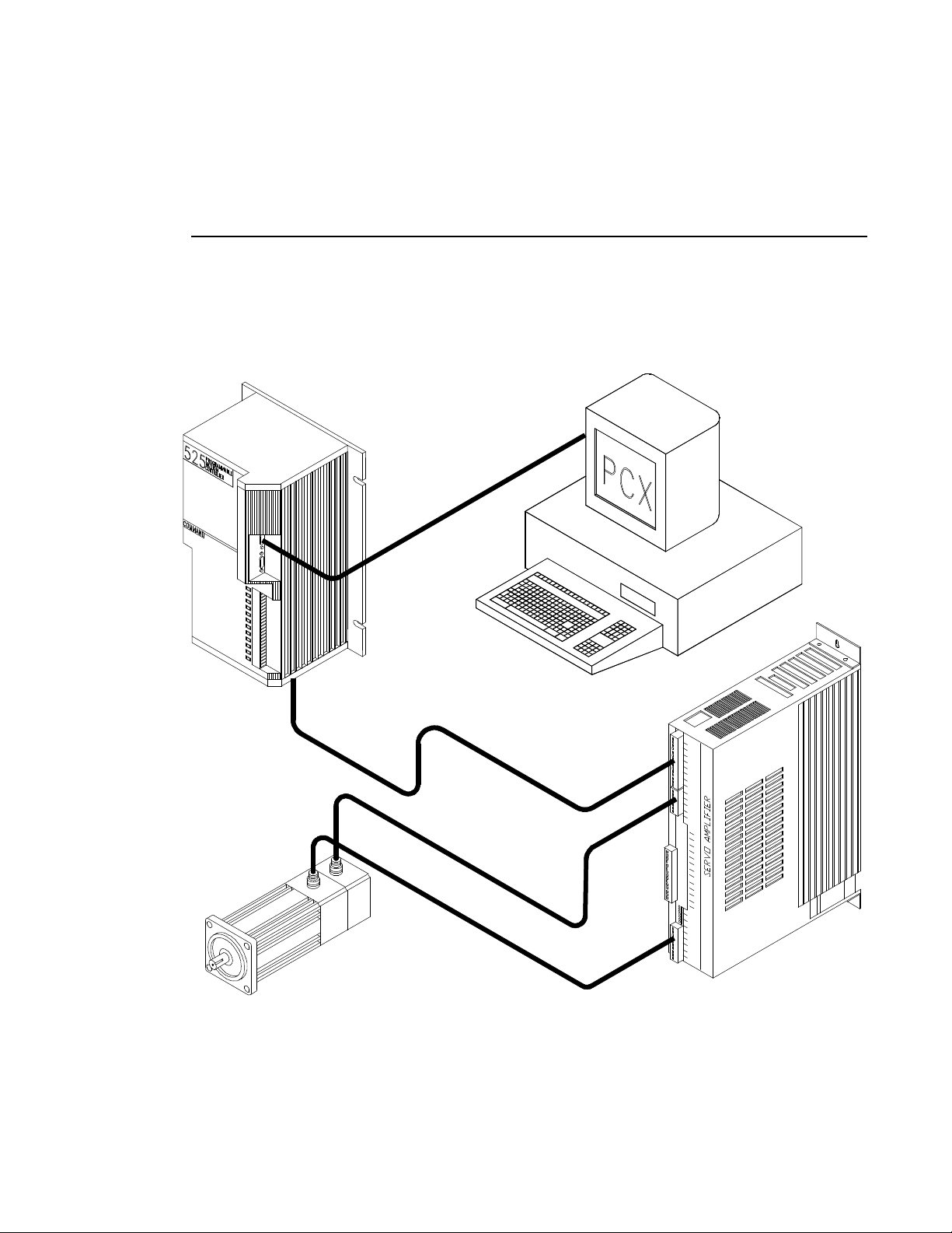
Figure 1 Typical 525 PMC Configuration
The 525 PMC outputs an analog velocity command signal and accepts encoder
feedback signals closing the position loop around an external servo drive.
Page 6

525 Programmable Motion Controller
The 525 PMC uses PCX Version 6.02 or newer for setup, calibration and
programming. A single PCX program can control multiple axes including a mixture
of Positioning Drives and 525 PMC's.
All 525 PMC gain settings are pre-programmed and can be changed from PCX
software (see PCX 6.X Operators Manual P/N 400240-01). A fine position loop
adjustment is provided on the front of the 525 PMC which allows you to fine tune
the system without requiring a personal computer. The servo amplifier and the 525
relationship is determined by a programmable command voltage to RPM ratio with
a default of 10 volts = max RPM of the motor.
The 525 PMC is designed accept a series of application modules called "PCM"
modules. The PCMs are attached by simply plugging them onto the front of the 525
PMC. The PCM modules are designed to share the 525's power supply and include
12 additional optically isolated inputs/outputs (making a total of 24).
The 525 PMC can operate with either 115 or 220 VAC single phase power (switch
selectable). The 525 PMC includes a pulse follower mode (see "Operating Modes"
on page 4).
External Drive Interface
The 525 PMC is designed to be used with common servo drive systems. A perfect
match is a servo drive that has a +/- 10 volt input equalling +/- maximum velocity
and an encoder feedback signal that equates to the actual motor position.
Command Signals
The 525 PMC command signal tells the servo amplifier (by the polarity and level of
the command) how fast and in what direction to move. The feedback position is
compared to the command position to determine whether the motor is doing what
it has been commanded to do. If an error between command and feedback exists,
the error is multiplied by a programmable gain and used to add or subtract the
command to the amplifier.
The input velocity scaling of the external drive must match the 525 PMC command
output scaling. By using the PCX system calibration screens, you can modify the
Calibrated Velocity and the Calibrated Velocity Command Voltage. Using these
values the 525 PMC is able to provide the proper command voltage with minimum
error.
Some drives have little or no speed regulation below 10% to 40% of the command
signal. Although this may be ok for simple velocity control, the 525 PMC must
control the speed from zero to ± full velocity. Without low speed regulation the 525
PMC cannot accelerate to the commanded speed without gross positional errors and
a possible fault condition.
The ability to accelerate or decelerate a load is a function of the external drive. The
525 PMC will linearize the velocity profile through positional feedback control. The
overall performance of the 525 PMC is tied directly to the drive's performance. The
525 PMC's ability to generate a command signal in excess of any particular drive's
capability does not mean that the 525 PMC can improve that drive's capability to
produce torque.
Special compensation of a specific amplifier may be required to accommodate a
specific application or load mismatch. Consult with the amplifier manufacturer for
specific details.
2
Page 7

Operating Modes
The 525 PMC offers three standard modes of operation: Indexing, Pulse and
Analog.
Indexing Mode
The indexing mode allows up to thirty-two different indexes or positions to be preprogrammed and stored in non-volatile memory. These indexes and other
commands such as stop and jog are selected by the drive's input/output (I/O) lines
from devices such as PLCs or operator push buttons. I/O connections can be used
for stand alone operation or in conjunction with one of the two control modes.
Another powerful feature of the indexing mode allows ASCII serial commands to be
received through the standard RS423 serial interface. This interface port allows
you to down-load new positional data such as distance, velocity, position etc.. The
ASCII serial commands work with the RS232C serial interface on an IBM (or
compatible) personal computer (PC) or programmable logic controller (PLC) with
an ASCII or basic module.
Pulse Mode
In the pulse mode the 525 PMC responds to a pulse train representing externally
generated incremental position change commands. These commands are normally
in the form of CW or CCW direction pulses. This mode is commonly used to when
replacing stepper motors.
Introduction
Analog Mode
In the analog mode the 525 PMC responds to a conventional +/- 10 volt signal. Most
variable speed drives and servo amplifiers on the market today receive commands
via analog input.
3
Page 8

525 Programmable Motion Controller
4
Page 9
Installation
525 Programmable Mo-
Installation Overview
The following installation requirements, methods and procedures are provided to
ensure reliable and trouble free installation and operation of your Emerson Motion
Control 525 PMC.
The methods and procedures are outlined on the following pages and include site
requirements, safety, power and fusing requirements, wire and transformer sizing,
noise suppression and I/O wiring.
The installer has the responsibility to comply with the safety requirements of the
system. This includes installing the system with an appropriate master interlock
switch for emergency shut down, using the proper wire and if necessary,
transformer sizes to fit the system. This section will provide you with the
information to complete a trouble free installation.
Safety
The user is responsible for providing emergency interlock switches that will
remove AC power from the system any time the equipment is not running, or
when the emergency stop is activated. This is to eliminate the possibility of
electrocution or unwanted movement of the motor. The safety ground
connections should only be disconnected for servicing, and only after all AC
power has been removed. Even after the removal of AC power, there is a
possibility of stored energy in the drives that must be dissipated before
servicing. Failure to follow proper safety procedures can cause death or
serious injury.
Disconnecting AC power does not immediately remove the stored energy in the bus
capacitance and the external drive may continue to operate until this energy is
dissipated. The time it takes to dissipate the energy in the bus capacitance greatly
depends on the current being drawn out of the capacitors.
Page 10

525 Programmable Motion Controller
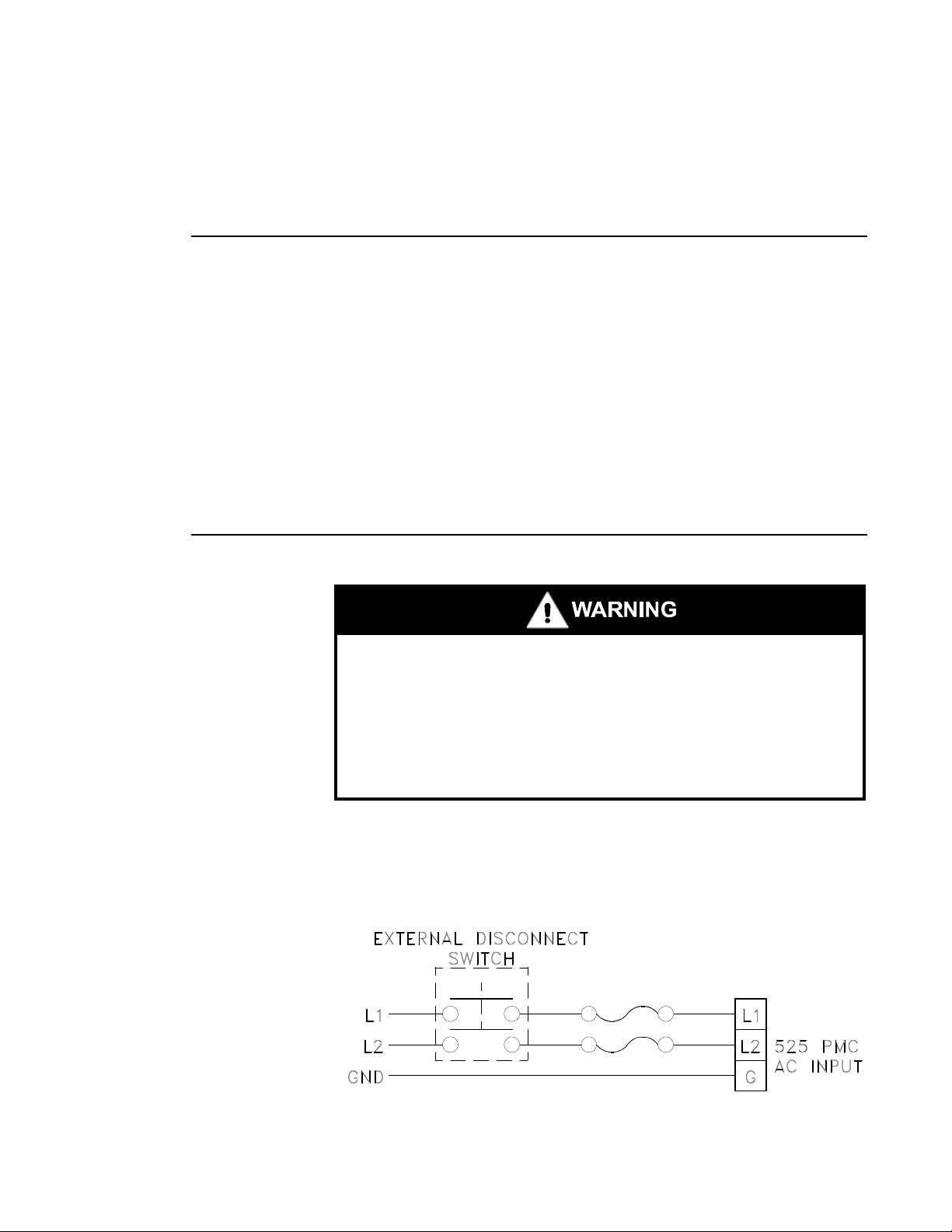
Figure 1 External Disconnect Example
AC Input Line
The AC line voltage of the input power must be within the specified range and free
of voltage transients that exceed this range. If this is not the case, additional AC
line conditioning may be required.
The AC input lines are connected to the 3-position terminal strip (L1, L2, GND)
located on the bottom plate of the 525 PMC. Power to the 525 PMC and the external
drive must be applied at the same time. To ensure proper operation after removing
power, wait a minimum of 10 seconds before re-applying power.
NOTE: The application of AC power to the 525 PMC must be
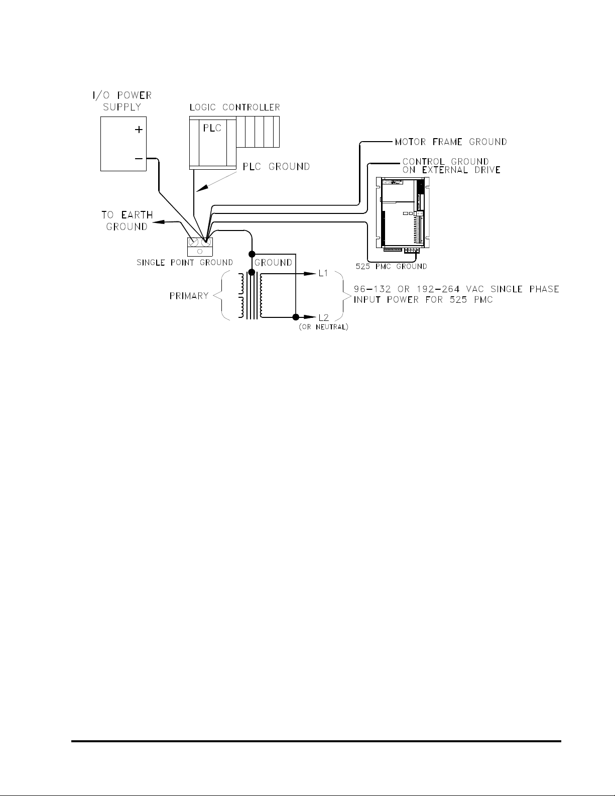
Grounding
The 525 PMC is internally grounded. The primary function of proper chassis
grounding is to ensure that the earth ground is connected to the AC ground input
of the chassis. Ground connections must be made from the chassis ground terminal
on each piece of equipment to a unique single point ground.
simultaneous with application of AC power to the controlled
external drive.
Connections should use the same gauge wire as the power input wire to the device
and not be shared with any other equipment. The motor cable should contain a
motor frame ground wire of at least the same gauge as the armature power
conductors.
All electrical cabinets and machine elements must be ground bonded together. 2
shows a typical grounding arrangement. To ensure proper grounding techniques,
please observe the recommendation of the IEEE Ground Book, ANSI Standards,
and the National Electrical Code.
2
Page 11
Installation
Figure 2 System Grounding illustration
Electrical Noise
If any sensitive electronic equipment (i.e. digital computer, test equipment, etc.) is
operating on the same line as the 525 PMC additional EMI/RFI filtering may be
required to reduce the effects of conducted noise. Effects of electrical noise on the
electronic equipment is greatly reduced when the techniques outlined below are
closely followed.
1. Do not run low power control signals and high power wiring in the
same raceway.
NOTE: If mixing wires cannot be avoided, then the low voltage control
input and output wiring must be shielded. The shield for these
wires should only be connected to ground at the source end of
the cable.
2. Connecting both ends of a shielded cable to ground may cause a
ground loop condition.
3. Keep all wires in the system as short as possible, with consideration
for troubleshooting and repair.
4. Follow the recommended grounding arrangements.
5. Suppression devices should be used on relays and coils as outlined in
the following section.
6. If control signal and high power wiring must cross, make sure they
cross at a 90 angle.
3
Page 12
525 Programmable Motion Controller
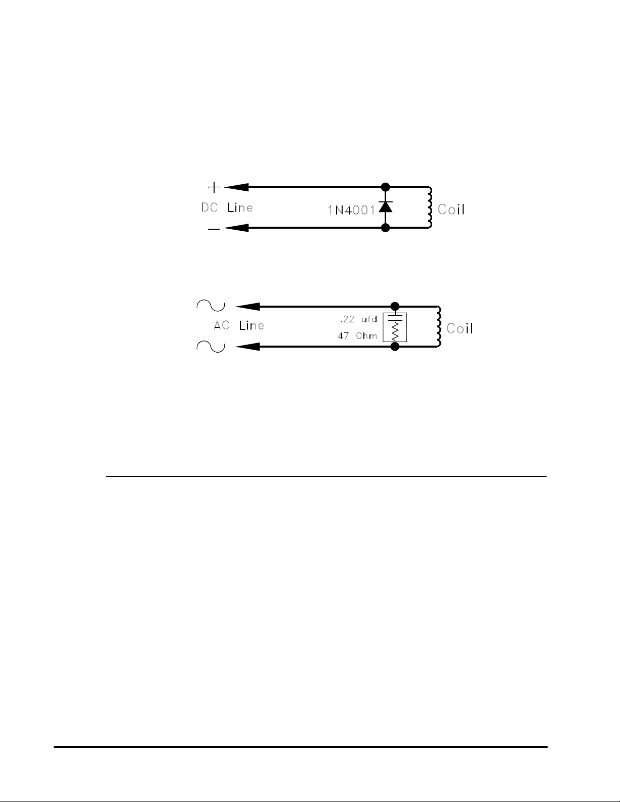
Magnetic Coil Noise
All relay coils, solenoid coils, electrical brakes and similar devices must be
suppressed. The placement of the noise suppressor should be as close to the coil as
possible.
In the case of DC coils, a diode is installed across the coil in a direction that will
cause the voltage transient to be supressed by the diode.
Figure 3 Magnetic Coil Noise (DC Line)
In the case of AC coils a capacitor and resistor are installed across the coil to
suppress the unwanted transient.
Figure 4 Magnetic Coil Noise (AC Line)
The specific values of resistance and capacitance may vary depending on the
inductance of the coil. Consult the relay manufacturer for the proper values to use.
These suppressor networks greatly extend the life of the contacts controlling the
coil because the transient energy, which can easily reach 1000 volts, shunts
through the suppressor rather than arcing across the controlling contacts as they
open.
I/O Wiring Layout
All signals to and from the 525 PMC must be connected with an electrical grade
insulated wire to withstand the application environment. Although each signal
input and output was designed for high noise immunity, careful wire routing within
the enclosure will help cut down electrical noise between I/O lines and noise
emitting conductors.
High voltage (>50V) must be separated from low voltage wiring in order to
minimize cross talk. High voltage signals should be run in a separate conduit
physically separated from the low voltage signals. In addition, any high current
carrying conductors should be twisted to minimize noise emission.
Conductor lengths should be as short as possible to reduce noise and losses in the
system. Input/output wiring can be safeguarded against noise by a shielded cable.
Brake leads should be treated as power conductors and run within the armature
conduit or raceway.
Shielding
When shielding cable it is important to know the difference between the types of
shielding available. A braid shield is the most effective way to minimize the effects
4
Page 13

of Electro-Magnetic Interference (EMI). A foil shield is the most effective way to
minimize Radio Frequency Interference (RFI).
A cable that provides both types of shielding is preferred, however, a braided shield
alone will usually provide adequate protection. To reduce chances of ground loops,
shields should be grounded only on one end, preferably at the signal source.
Selecting An Enclosure
The Emerson Motion Control 525 PMC is designed for the industrial environment.
However, no sophisticated electronic system can tolerate certain atmospheric
contaminants such as moisture, oils, conductive dust, chemical contaminants and
metallic particles. Therefore, if the 525 PMC is going to be subjected to this type of
environment, it must be back mounted verticality in a metal NEMA type 12
enclosure. Proper ventilation and filtering must also be provided. If the equipment
environment is above 80 F, cooling should be considered.
Enclosure Size
The size of the enclosure will determine how long it takes the temperature inside to
rise. It will also affect the thermal transfer of the enclosure. Normally, the larger
the enclosure the better the thermal transfer. Thermal transfer is also affected by
venting, forced air cooling, and the enclosure material.
Installation
5
Page 14
525 Programmable Motion Controller
Encoder Feedback
The 525 PMC utilizes an xe "ENCODERS:Incremental Encoder" incremental
encoder as the feedback device from the motor. The type of encoder used must have
two complimentary channels electrically spaced 90 from each other. These encoder
channels are usually designated as CHA and CHB. To fully utilize the motion
controller, the encoder must have a third complimentary channel that has a once
per revolution output called Mark, or Index.
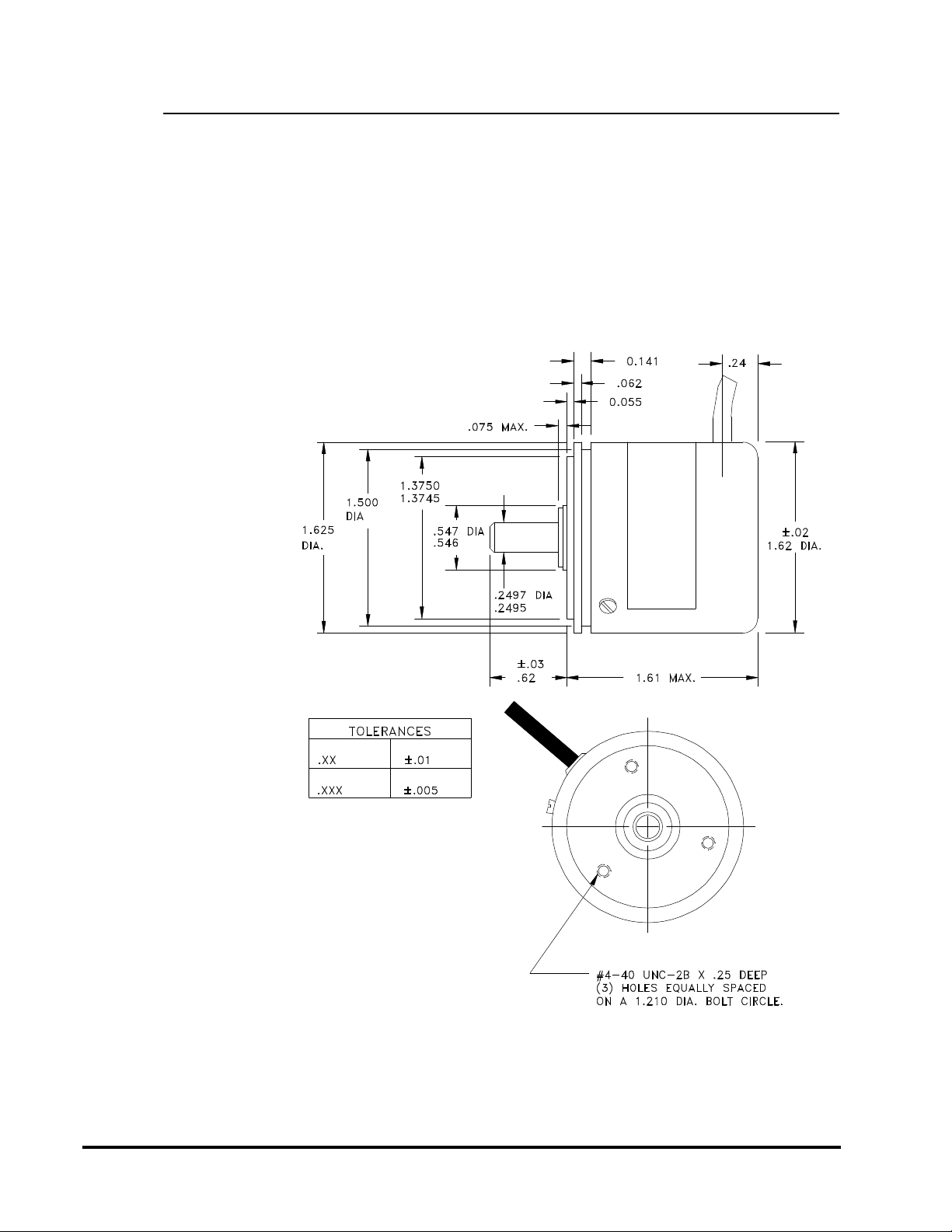
Emerson Motion Control can provide two encoder configurations for use with the
525 PMC.
Figure 5 Encoder Model SDC-15-1, 1024 Line Density
6
Page 15
Installation
NOTE: The use of a flexible coupling is required between the encoder
and the motor shaft.
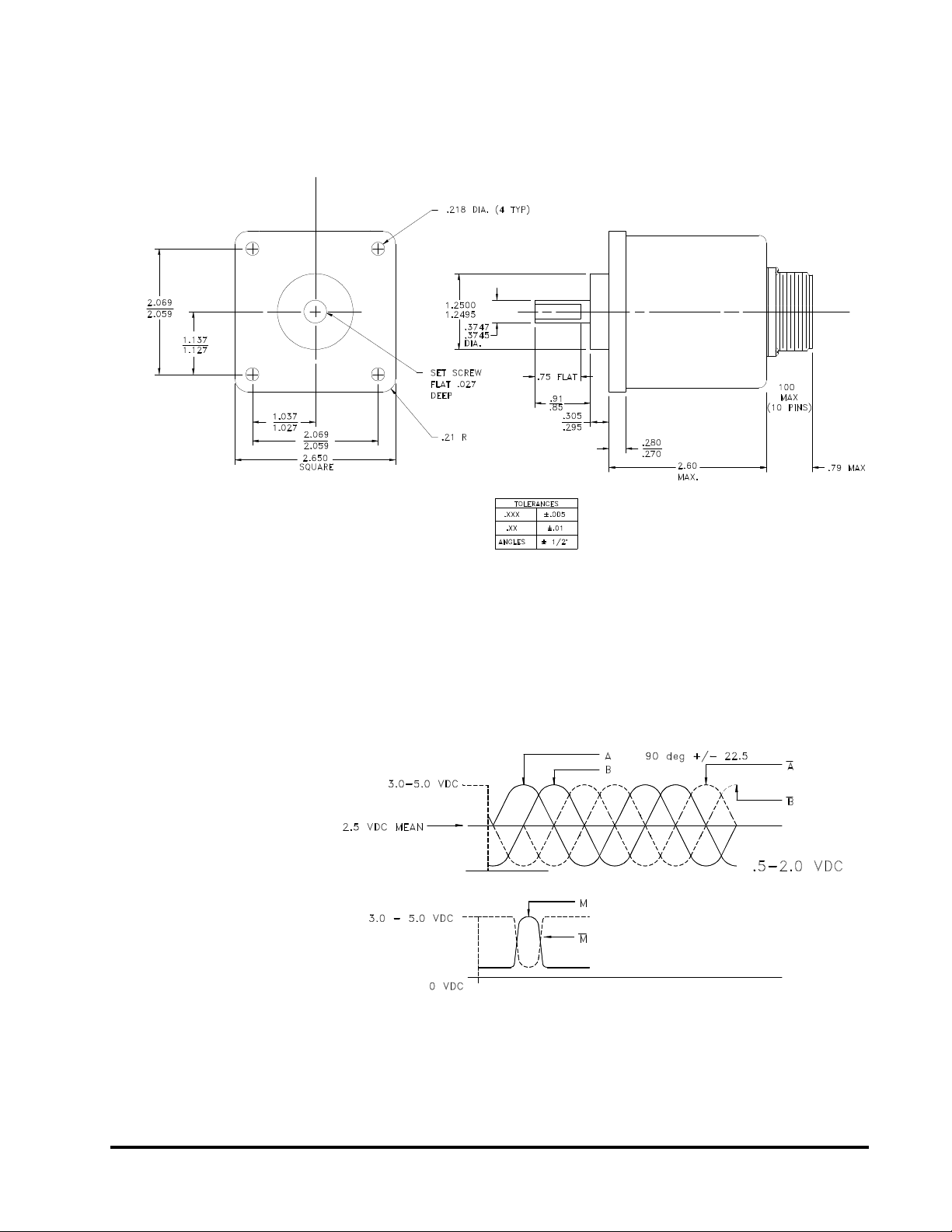
Figure 6 Encoder, Model SDC-25-1, 1024 Line Density
NOTE: The use of a flexible coupling is required between the encoder
and the motor shaft.
Encoder Sine Wave Signals
A graphic illustration of the encoder signals from either the SDC-15-1 or SDC-25-1
is shown below.
Figure 7 Typical Encoder Signals - Sine Wave Output
A line on an encoder would be 360° of signal change of either A or B.
7
Page 16

525 Programmable Motion Controller
Encoder Square Wave Signals
Sine wave signals are recommended because they are least affected by long cable
lengths so that signal deterioration is negligible. TTL style encoders can also be
connected to the 525 PMC. The signal levels for TTL encoders are similar to the
desired amplified sine wave signals.
Figure 8 Typical Encoder Signals - Square Wave Output
Encoder Signal Quality
Any distributed capacitance in the interface cabling reacts to this frequency as an
impedance to couple unwanted signals on the adjacent lead. Extreme care must be
taken to minimize these unwanted effects. If care is not taken the resultant signal
to the 525 PMC could look like this:
Figure 9 Encoder Signals As A Result Of Noise
The 525 PMC can not decode this properly. These signals are deteriorated because
of cross coupling through the cabling. The signals have to be as shown in figure 8.
8
Page 17

Encoder Feedback Cables
The encoder must be connected to the motor so a clockwise rotation of the motor
shaft, as viewed from the shaft end of the motor, will cause a count up condition.
The cable drawings below (for the two types of encoders EMC supplies) assume that
CW motor rotation will cause CW encoder shaft rotation. This is the case if the
encoder is mounted on the rear of the motor.
Figure 10 Model SDC-15-1 Encoder Connections
Installation
Figure 11 Model SDC-25-1 Encoder Connections
9
Page 18

525 Programmable Motion Controller
External Drive Connections To The 525 PMC
The 525 PMC has two keyed, detachable terminal blocks on the bottom of the unit
for connecting the external drive and encoder. The terminal blocks are divided into
two sections of 13 (1-13 & 14-26). Connections should be made using wire no larger
than 18ga. The following is a breakdown of the signals available at the terminal
blocks.
Connector Pin#Signal Description
1 Encoder signal input A
2 Encoder signal input A not
3 Encoder signal input B
4 Encoder signal input B not
5 Encoder signal input M
6 Encoder signal input M not
7 Encoder +5VDC Supply
8 Encoder Shield & Command Shield
9 Encoder Ground
10 Command (+)
11 Command (-)
12 Feedback current (+)
13 Feedback current (-)
14 Input 1 (+)
15 Input 1 (-)
16 Input 2 (+)
17 Input 2 (-)
18 Reserved for future use
19 Reserved for future use
20 Shield
21 Drive enable NORMALLY ON (-) EMITTER
22 Drive enable NORMALLY OFF (-) EMITTER
23 Drive enable (+) Common Collector (dirve enable only)
24 Drive reset NORMALLY ON (-) EMITTER
25 Drive reset NORMALLY OFF (-) EMITTER
26 Drive reset (+) Common Collector (drive reset only)
10
Signal Discriptions
Encoder input signals
The encoder input signals - A, A not, B, B not, M, M not are directly connected to
the motor encoder. The signals should have a minimum 2.5 V and a maximum 5.0
VDC peak to peak voltage with a 2.5 VDC reference. Sine wave encoders are
recommended due to their inherent noise immunity. Square wave encoders can also
be used if care in cable selection is taken.
Encoder +5VDC supply
+5VDC and ground is provided to power the encoder. Maximum current output is
150 ma. If the encoder to be used exceeds this limit an external power supply will
have to be provided and grounded to the encoder ground on the terminal block.
Page 19

Installation
Shield
Two shield terminals are provided as a connection point for cable shields. These two
terminals are connected internally to the input power ground terminal on the unit.
Shields should be connected on one end only, preferably at the 525 PMC.
Command (+) and Command (-) Output
Command (+) and Command (-) is the analog output signal from the 525 PMC to
the external drive's velocity command input. This signal can be scalable from +/-5
volts = maximum velocity to +/-12 volts = maximum velocity at a minimum load
impedance of 4.7K. The Command (-) signal has a ground reference to the input
power ground of the 525 PMC.
NOTE: It is important that the control ground on the amplifier is
connected to the input power ground on the 525 PMC.
Command Output Polarity
A positive voltage out of the command output must cause a clockwise rotation of the
motor shaft as viewed from the shaft end. The encoder should turn clockwise as
viewed from the shaft. This will ensure a positive count within the 525 PMC.
Signal Path
The command (-) output is internally connected to ground within the 525 PMC.
Consequently, the (-) input to the external drive must have a ground reference. The
figures below show the two most typical connections to an external drive.
Figure 12 Single Ended Input Configuration
11
Page 20

525 Programmable Motion Controller
Figure 13 Differential Input Configuration
Feedback Current
Feedback current (+) and Feedback current (-) are inputs to allow the 525 PMC to
monitor the motor current via the voltage proportional to current output on the
external drive amplifier. This analog input is scaled at +/-5VDC = continuous
current and +/-10VDC = peak current. Fault times range from 4-10 seconds at
slightly greater than continuous current to 2-4 seconds at peak current. This is a
high impedance input which is referenced to logic ground. Scaling of this input is
programmable.
Inputs 1 & 2:
Inputs 1 & 2 allow for external drive's fault indications to be sent to the 525 PMC.
A fault on Input 1 will produce a "9" on the display of the 525 PMC and a fault on
Input 2 will produce a "11". Polarity of these inputs is programmable. If one or both
of these inputs are not used they should have their polarity set at (-) with the "Setup
Menu" of PCX (see PCX 6.X manual) or with serial commands. Typical input
configuration is shown in 14.
Figure 14 Input Polarity
Drive Enable Outputs
The drive enable outputs allow the 525 PMC to disable the external drive during
power up, a bridge inhibit or a fault condition. The output is provided with both
normally on and normally off outputs. To utilize the normally on output connect
between drive enable (+) and normally on drive enable (-). Consequently, to utilize
the normally off output connect between drive enable (+) and normally off drive
enable (-). The (+) indicates the collector of an optical isolator while the (-) indicates
the emitter.
12
Page 21

Installation
Figure 15 Drive Enable Outputs
During a reset, bridge inhibit or a fault the normally on output is off and the
normally off output is on. During operation the normally on output is on and the
normally off output is off.
Drive Reset Outputs
The drive reset outputs allow the 525 PMC to reset the external drive after a fault.
The output is provided with both normally on and normally off outputs. To utilize
the normally on output connect between drive reset (+) and normally on drive reset
(-). Consequently, to utilize the normally off output connect between drive reset (+)
and normally off drive reset (-). The (+) indicates the collector of an optical isolator,
while the (-) indicates the emitter as shown below.
Figure 16 Drive Reset Outputs
During a reset the normally on output is on and the normally off output is off. After
completion of the reset and during operation, the normally on output is off and the
normally off output is on.
13
Page 22

525 Programmable Motion Controller
Minimum System Configuration
The following diagram illustrates the minimum 525 PMC system configuration.
14
Figure 17 Minimum System Configuration
A positive command voltage to the external drive must cause CW motion of the
motor as viewed from the shaft end of the motor. This is a minimum interface with
no optional I/O shown (i.e., thermal fault, drive fault and brake output). Ensure
that the fault input polarities are set normally off to prevent unwanted faults.
Page 23

Operating Modes
The primary operating mode is the indexing mode. The indexing mode is available
at all times and is independent of any alternative operating mode switch settings.
The two variations of the indexing mode are shown in 0. Switches 3 and 4 of the
four position dip switch are used to configure the alternative operating modes.
Table 1 Indexing Modes
Mode Control Interface Command Device
Indexing Index, Home, Jog Inputs/Outputs
Indexing Index, Home, Jog
In addition to the indexing mode, four alternative operating modes are also
available (see 2). These modes are called Pulse/Pulse, Pulse Direction Analog
Velocity and Analog Torque.
& Motion
Programming
10 to +30VDC
Optically Isolated
(sink or source)
RS423/422/232C
Serial Interface
XMIT/REC ASCII
Installation
Relay logic,
Operator Control
Panel or PLC
Personal Computer
ASCII Unit on PLC
ASCII Terminal
Table 2 Alternative Modes
Mode Control Interface Command Device
Pulse/
Direction
Pulse/Pulse Position
Analog Velocity Zero to ±10 VDC Velocity Controller
Analog Torque Zero to ±10 VDC Velocity Controller
Position
Increments
Increments
Pulse & Direction
TTL Logic Levels
CW & CCW Pulses
TTL Logic Levels
Motion Generator,
Indexer, CNC
Motion Generator,
Indexer, CNC
NOTE: Indexing operations may be performed in all modes under
serial control.
15
Page 24

525 Programmable Motion Controller
Mode Selection
18 defines the switch settings for the four alternative modes of operation.
16
Figure 18 Dip Switches/Mode Selection (Factory Defaults Shown)
Page 25

Pulse Mode
In the Pulse mode the 525 PMC responds to a serial pulse train representing
externally generated incremental position change commands. This mode is
commonly used to control DC stepper motors or numeric controlled (CNC)
machinery. The Pulse/Pulse or Pulse/ Direction operation are provided so that
pulse inputs are converted to velocity and distance.
With the Pulse/Pulse option two inputs are configured for clockwise and counter
clockwise pulses. Pulses on the CW pulse input line cause the motor shaft to rotate
CW and pulses on the CCW pulse input line cause CCW rotation of the motor shaft.
In the Pulse/Direction option the same input lines are used. However, one input line
is configured for the control pulses and the other input line is used to control the
direction. If there is no current flowing in the direction input, pulses on the pulse
input line will cause CCW rotation.
In either pulse mode, once motion is initiated with these inputs, motion in the
opposite directions can not be achieved until motion in the initiated direction has
been stopped by stopping the incoming pulses.
Installation
Figure 19 Pulse Mode
In a pulse train application the pulses are fed into the CW and CCW inputs on the
15 pin DB style command connector (pins 4, 2 and 5, 3 respectively). The inputs can
be used for sinking or sourcing current; this requires two connections per input. In
either case (sinking or sourcing), the noise immunity is improved when the normal
state of the input does not cause current to flow in the optical coupler.
17
Page 26

525 Programmable Motion Controller
Figure 20 Command Connector Circuit
Current should only flow when a motion pulse is applied by the external pulse
generator and each voltage pulse must be at least 1.5 micro seconds wide and
between 2.4 and 5.5 VDC (TTL compatible) to be accepted as a valid pulse. The
user's signal driver must be able to supply 25mA (either sinking or sourcing). If
open collector logic devices are used in a sinking connection, pull-up resistors may
be necessary.
The speed of the system is based on the pulse frequency and can be changed by
changing the value of "Steps Per Revolution" in the PCX Parameters screen (see
PCX manual). the maximum pulse frequency is 210 KHz.
NOTE: CW rotation of the motor is established with the operator facing
the shaft end of the motor.
18
Page 27

Installation
Figure 21 Example Of Sinking/Sourcing Connections
Any connections between the customer supplied interface (stepper controller, etc.)
and the command connector should be made through a shielded cable. The shield
of this cable should be connected to the customer interface ground (source end). If
no shield connection is available at the source end, then the shield connection on
the command connector (15 pin) may be used. Keep in mind that this shield
connection is connected internally to chassis ground of the drive.
The "STOP" I/O function must be held "Active" to prevent motion. if the
"Stop" I/O function is not held "Active", the operator must stop incoming
command voltage to avoid motion. Failure to follow proper safety procedures
can cause death or serious injury.
19
Page 28

525 Programmable Motion Controller
Analog Mode (Velocity or Torque)
In the Analog mode (torque or velocity) the servo amplifier responds to a
conventional ±10 volt DC signal. Most variable speed drives and servo amplifiers on
the market today receive commands via this type of signal.
When the DIP switches are set to enable the analog mode the display character of
the 525 PMC will be an (A). In analog mode a 0 to 10 volt command signal is
equated to 0 to maximum velocity or peak torque.
The 525 PMC can receive external input commands and serial commands while in
analog mode. For example: When in analog mode and you initiate an index, home
or jog command via an input the (A) on the diagnostic display will be replaced with
an (E) and the requested motion occurs. Upon completion of the requested motion
the 525's operating mode will automatically change back to analog mode (A).
You can also temporally change the operating mode by sending an SC=1 (serial
command) to the 525 PMC. This would disable analog control and enable serial
control displaying an (E.) on the diagnostic display at which time the 525 PMC
would be able to receive motion commands via serial commands or inputs. Upon
completion of the requested motion the 525's operating mode will automatically
change back to analog mode (A). To change the 525's operating mode serially, use
the SC=0 command.
In either of the two analog modes of operation a ±10 VDC signal is equated to either
(CW) or (CCW) maximum programmed velocity in the velocity mode or CW or CCW
full peak torque rating in the torque mode. The mode of operation can be selected
via the mode select switches on the front of the 525 PMC.
NOTE: CW rotation is defined while facing the shaft end of the motor.
20
Figure 22 Analog Velocity/Torque Mode
Page 29

Installation
In velocity mode the ±10 VDC command signal is connected through the 15 pin DB
style command connector. The input circuit of the 525 is a differential input
amplifier with the following characteristics:
• Application of a + voltage to pin 7 with respect to pin 13 (GND) will
produce either a CW motion or torque in the CW direction as viewed
from the shaft end of the motor.
• Application of a - (negative) voltage to pin 7 with respect to pin 13
(GND) will produce a CCW motion or CCW torque. The opposite
conditions are true if the analog voltage is applied to pin 6 with
respect to pin 13. The analog voltage can also be applied between pins
6 and 7 for a true differential input.
Figure 23 Command Input Circuit
Voltages on pins 6 or 7 must not exceed ±12 VDC with respect to pin 13,
analog ground
Figure 24 15 Pin Command Connector
21
Page 30

525 Programmable Motion Controller
NOTE: Both the hardware and software position travel limits are active
The "STOP" I/O function must be held "Active" to prevent motion. if the
"Stop" I/O function is not held "Active", the operator must stop incoming
command voltage to avoid motion. Failure to follow proper safety procedures
can cause death or serious injury.
Serial Interface
All 525 PMC's are equipped with two RS423 serial interface connectors which are
RS232C/RS422 signal compatible. The serial interface has a DIP switch selectable
baud rate ranging from 110 to 19200 bps and is connected using a simple three wire
hook-up; transmit, receive and signal ground. Transmission is accomplished using
standard printable ASCII characters. This means that the 525 PMC can also
communicate over the serial interface with a remote terminal.
Serial A
All programming is done through the "Serial A" connector. The serial cable should
be shorter than 50ft in order to comply with RS232 specifications. However, longer
cable lengths can be possible at slower baud rates. (Less than 4800 bps).
if they are set up.
Serial B
The 525 PMC also includes a second 9 pin RS423 serial connector designated as
"Serial B", which is used for a multi-drop networking scheme to other drives. This
second connector cannot be used for programming other than in a multi-drop set up.
Multi-Drop Configuration
When using multi-drop configuration, the 525 PMC can automatically detect when
there are other units "down the line" and redirect its serial signals to the
appropriate drives or 525's. The serial commands are sent to the appropriate unit
based on the axis identifier dip switch settings. Each 525 PMC in a multi-drop
configuration must have a unique axis identifier code and must be set up for full
duplex mode.
22
Page 31

Figure 25 Multi-Drop Connection
Figure 26 Serial Signal Flow Diagrams
Dip Switch Settings
The DIP switch numbers and their corresponding functions are shown below.
Installation
23
Page 32

525 Programmable Motion Controller
24
Figure 27 Dip Switches (Factory Defaults Shown)
Page 33

Dip Switch Function Descriptions
Baud rate switches
Switches 1, 2 and 3 of the eight position DIP switch are used to match the baud rate
of the drive to the baud rate of the programming device. If the two baud rates are
not the same, serial communication will not be possible.
Axis identifier switches
Switches 4, 5, 6, 7 and 8 are used to distinguish between drives in a multi-axis
application. This allows each axis to be programmed individually over the same
multi-drop serial cable.
Duplex switch
Switch 1 of the four position DIP switch sets either half or full duplex mode. In half
duplex mode the serial data is not echoed back to the programming device for
conformation or display. In full duplex mode the data is echoed back to the
programming device, allowing the data to be verified. In most cases full duplex is
the preferred mode of operation.
Installation
NOTE: All drives in a multi-drop configuration must be set to full
Auto line feed
Switch 2 is used to determine if a line feed character should be echoed back to the
programming device when a carriage return is received. This will alter the line
spacing on the programming monitor.
Framing information
When using serial communication, the data must be sent as a string of continuous
bits. This string of data bits must be "framed" by start and stop bits so that valid
data can be recognized. The framework which the drive will recognize is as follows:
1 start bit
8 data bits
1 stop bit
The high order data bit is ignored by the drive. A parity bit may therefore be sent
to the drive along with only seven data bits. When transmitting, the drive will
always send a zero for the eighth data bit.
Serial Cables
The maximum allowable length of serial cable used with the 525 PMC is 50 feet.
This limitation is a result of the following statement from the EIA RS-232C
specification:
duplex mode.
"The use of short cables (each less than approximately 50 feet or 15 meters) is
recommended; however, longer cables are permissible, provided that the resulting
load capacitance measured at the interface point and including the signal
terminator, does not exceed 2500 picofarads".
25
Page 34

525 Programmable Motion Controller
In 525's, the signal terminator capacitance is approximately 1000pf and a typical
cable capacitance runs about 30pf/ft. Therefore, the cable length should be limited
to 50 feet. Longer serial interface cables are not recommended.
In multi-drop configurations, the ground reference (earth ground) for each
communicating device must be at the same potential. The further apart the
communicating devices, the more difficult this is to achieve. Therefore, it is a good
idea to keep the multi-drop loop as short as possible. This condition is not as critical
if all of the communicating devices are optically isolated.
It is very important that the serial cables are not altered in the field. It is also
important to follow any recommendations given in the product manuals on how to
connect or terminate these cables.
NOTE: As a general rule, the minimum cable bend radius is ten times
TIX-25 CABLE
COMPUTER/TERMINAL
TYPICAL IBM 25F PIN RS232 STYLE
XMIT REC
TIX-25 CABLE
COMPUTER/TERMINAL
TYPICAL IBM 9F PIN STYLE
XMIT REC
GND
GND
the cable outer diameter.
2
3REC
7
3
2REC
5
SHIELD
SHIELD
FX DRIVE
SERIAL A
2
3 RX
5
GND
1
SHLD
9 PIN MALE
"D" TYPE
FX DRIVE
SERIAL A
2
3 RX
5
GND
1
SHLD
9 PIN MALE
"D" TYPE
26
Figure 28 TIX-XXX & TIA-XXX Wiring Diagrams (525 PMC To IBM
Serial Port)
FX DRIVE 1
SERIAL B
SHLD
TX
MEN
GND
RXM
TXM
N/C
N/C
9 PIN MALE
"D" TYPE
1
2RX
3
4
5
6
7
8
9
FX DRIVE 2
SERIAL A
1
2 RX
3
TX
4
MEN
5
GND
6
RXM
7
TXM
8
N/C
9
N/C
9 PIN MALE
"D" TYPE
Figure 29 DD-XXX Wiring Diagram ( Multi-Drop Cable)
NOTE: For wiring diagrams of Emerson Motion Control T-60 (NMA-
XXX), T-61 (NMB-XXX) or T-21 refer to the operators manual that
accompanied that device.
Page 35

Input Output Interface
The 525 is equipped with 8 inputs and 4 outputs which operate on +10 to +30 vdc.
Each input and output has 2 screw terminals associated with it to provide for either
sinking or sourcing operation. The first 8 pairs of designated terminals are inputs
and the last 4 pairs of terminals are outputs (see 30). The outputs are capable of
sinking or sourcing 200 mA. It is the operators responsibility to limit the output
current to less than or equal to 200 mA.
These inputs and outputs allow for proper timing and coordination between the
525's motion and other machine control functions. The inputs and outputs typically
are connected to the machine's programmable logic controller (PLC) or external
drive. These inputs and outputs can also be connected to limit switches, and/or
switches and indicators on an operator's control panel.
A wide range of input/output control functions are provided. The functions used are
assigned to any of the input/output lines. This is accomplished through either
serial interface commands or by using the PCX software provided with the 525.
Inputs may be programmed as normally off or normally on. In addition, more than
one function may be assigned to the same input line.
Inputs and outputs for control and status are wired to a detachable terminal strip
which makes servicing easy. All I/O wiring must be done with 18 to 24 gauge wire
and must be industrial grade insulated wire that will withstand the environment
of the application. The use of larger gauge wire will cause the I/O terminals to
prematurely fatigue.
Installation
NOTE: To improve noise immunity, Emerson Motion Control
recommends using twisted pair wire for the I/O wiring. In
extremely electrically noisy environments, shielded, twisted
pairs should be used with the shield connected to the safety
ground via a low impedance conductor.
Each input and output to the control unit is designed to have high noise immunity.
However, this does not mean that high voltage, noise emitting wiring on the rest of
the application can be run adjacent to the control inputs. Precautions outlined in
the "ELECTRICAL NOISE" section (page 2-4) should be followed.
An LED indicator is associated with each input and output. The input and output
indicators are on if current is flowing in the associated line.
Figure 30 I/O Nomenclature
27
Page 36

525 Programmable Motion Controller
Input and Output Functions
The basic drive can be configured from a list of 21 input functions and 10 output
functions. When a IOM/PCM module is added the number of available I/O functions
is increased.
NOTE: For detailed description of I/O functions see PCX
PROGRAMMING MANUAL P/N 400240-01.
28
Figure 31 Input and Output Wiring, Sinking and Sourcing
NOTE: 18 to 24 gauge wire should be used for I/O wiring. The use of
larger gauge wire will cause the I/O terminals to prematurely
fatigue. DC common should be grounded to the single point
ground.
NOTE: The DC Common of the I/O power supply must be grounded to
the safety ground.
Page 37

Installation of Application Modules
The IOM-1 and PCM application modules allow for memory expansion, I/O
expansion and more complex motion programming capability. The IOM-1 and PCM
application modules (Programmable Control Module) attach to the front of the drive
amplifier with two locking arms. All electrical connections (except I/O) are made via
the 48 pin connector.
NOTE: For programming and operation of the PCM Modules, see "PCX
VERSION 6.X OPERATORS" Manual P/N 400240-01.
Installation
Figure 32 IOM/PCM Module Connection
PCM Modules I/O Connections
All PCM application modules are equipped with 8 inputs and 4 outputs which are
optically isolated for +10 to +30 vdc operation. Each input and output has 2 screw
terminals associated with it to provide for either sinking or sourcing operation. The
first 8 pairs of designated terminals are inputs and the last 4 pairs of terminals are
outputs. The outputs are capable of sinking or sourcing 200 mA. It is the users
responsibility to limit the output current to less then or equal to 200 mA.
Adding a IOM-1 or a PCM module will double the I/O capabilities of the 525 PMC.
The number of input lines are increased from 8 to 16 and the number of output lines
is increased from 4 to 8.
The inputs and outputs allow for proper timing and coordination between the
drive's motion and other machine control functions. The inputs and outputs
typically are connected to the machine's programmable logic controller (PLC) or
29
Page 38

525 Programmable Motion Controller
relay logic system, however, these inputs and outputs can also be connected to limit
switches, and/or switches and indicators on an operator's control panel.
30
Figure 33 I/O Connections (IOM-1 And PCM Modules)
NOTE: 18 to 24 gauge wire must be used for I/O wiring. The use of
larger gauge wire will cause the I/O terminals to prematurely
fatigue.
Page 39

Fault Polarity and
525 Programmable Mo-
Overview
Fault Polarity
Calibration
The PCX 4.5 software package provided with each 520 PMC allows setting the
polarity of the inputs on the drive interface terminal strips. It also allows for system
calibration.
The Fault Input polarity feature allows the user to adapt the 520 PMC to various
fault output schemes. The polarity can either be set to the "+" condition (normally
on) or to the "-" condition (normally off). Normally on indicates that current through
the input electronics is the operating condition and that interruption of that current
will yield a fault. Normally off indicates that the absence of current through the
input electronics is the operating condition and that the addition of current will
yield a fault. A fault on Input 1 will produce a "9" on the display and a fault on Input
2 will produce a "11" on the display. If the application does not use the fault inputs,
both must be set to the "-" condition.
Setting the Fault Input Polarity
The 520 PMC Fault Polarity can be setup by moving through PCX to the fault input
setup screen. follow the sequence below to arrive at the proper screen.
select: On-line Operations (COM1 or COM2), Drive Setup, Drive Configuration 520
PMC Setup, Fault Input Setup
Page 40

525 Programmable Motion Controller
Figure 1 Fault Input Setup (Fault 9)
The cursor is then located on the polarity of either Input. Use the UP/DOWN arrows
to position the cursor on the desired input to be changed. Use the LEFT/RIGHT
arrows to toggle the polarity to "+" and "-". Once the desired polarity is shown, enter
a carriage return to enter the polarity.
Figure 2 Fault Input Setup (Fault 11)
System Calibration
The System Calibration feature allows you to setup the calibration and loop gain of
the 520 PMC/external drive combination to maximize system performance. Enter
the Calibrate Velocity (maximum drive velocity) and the Calibrate Velocity
Command Voltage (command voltage required to produce maximum velocity). With
these two parametersyou, the 520 PMC calculates the proper command voltage
needed to produce the desired motion profile. The Encoder Lines Per Revolution is
currently fixed at 1024.
You can jog the motor at various velocities through the Calibrate Jog Velocity
selection. By monitoring the Following Error when jogging at various velocities, you
can "fine tune" the system so a perfect match between the 520 and the external
drive is achieved. "Fine tuning" may consist of slightly altering the Calibrate
Velocity or Calibrate Velocity Command Voltage on the 520 or by altering the
command scaling or the offset adjustments on the external drive.
In addition, pre-programmed indexes may be executed to allow monitoring and
adjustment of Position Loop Gain. Position Loop Gain should be set as low as
possible to permit satisfactory operation while not creating an instability in the
system. In some circumstances, modification of the external drive may be required
to allow for proper operation.
Lastly, the Position Loop Gain Adjustment Range is setup. This parameter limits
the amount of Loop Gain adjustment from the UP/DOWN switch located on the
front of the 520 PMC. By setting this parameter to 0%, the UP/DOWN switch has
no effect on Position Loop Gain. By setting this parameter to 100%, the UP/DOWN
switch has full Position Loop Gain adjustment capabilities.
2
Page 41

Setting the System Calibration
After following the examples in the "Setting the Fault Input Polarity" section,
proceed to the 520 PMC Setup Options menu. By moving the cursor to the System
Calibration position and entering a carriage return, the user enters the System
Calibration menu as shown below.
Fault Polarity and Calibration
Figure 3 System Calibration (Calibrate Velocity)
Position the cursor on the Calibrate Velocity selection. Enter the maximum velocity
of the external drive at the maximum velocity command voltage followed by a
carriage return. The cursor will now be positioned on the Calibrate Velocity
Command Voltage as shown below.
Figure 4 System Calibration (Command Voltage)
Enter the command voltage necessary to produce the Calibrate Velocity just
entered in volts followed by a carriage return. If unsure about these two
parameters, consult the owners manual of the external drive. The cursor will now
be positioned on the Encoder Lines Per Revolution.
3
Page 42

525 Programmable Motion Controller
Figure 5 System Calibration (Encoder Lines)
This default value is fixed at 1024 lines per revolution and may be altered. Enter a
carriage return and the cursor will now be positioned on the Calibrate Jog Velocity
selection.
Figure 6 System Calibration (Jog Velocity)
In this position the user can jog the motor at any velocity while being able to
monitor the following error scaled in encoder lines of error. It is also at this point
that the offset of the external drive can be adjusted. By leaving the motor at rest,
monitor the following error while adjusting the offset adjustment of the external
drive. Adjust this offset to minimize the following error,preferably as close to 0 as
possible. After completion of the offset adjustment, a running adjustment to "fine
tune" the system is performed.
NOTE: The motor shaft must be free to rotate indefinitely during this
test or else machine damage may occur. The space bar is used
to start and stop motion. If unable to allow indefinite rotation,
care must be taken to prevent reaching travel limits.
4
Page 43

Fault Polarity and Calibration
Enter a "Calibrate Jog Velocity" of a very low value (e.g., 30 RPM) and enter a
carriage return. Ensure that the shaft of the motor is free to rotate and depress the
space bar to begin motion. Observe the "Following Error". If the following error is
above 2 or 3 counts, one of two things should be done. Either a small adjustment of
the command scaling of the external drive is required or the "Calibrate Velocity
Command Voltage" will have to be changed slightly to reduce the following error.
If using the command scaling adjustment on the external drive,(usually a pot)
slowly turn the pot in one direction. If the Following Error becomes larger, turn the
pot in the opposite direction. Adjust the pot to obtain the lowest Following Error
possible. Increase the "Calibrate Jog Velocity" in 500 RPM increments until the
maximum drive velocity is reached, adjusting the command scaling pot as
necessary at each increment.
If the external drive has a fixed command scaling, the "Calibrate Velocity
Command Voltage" will have to be adjusted. Change this value up or down 0.1 volts
in one direction. If the"Following Error" increases, set the value 0.1 volts in the
opposite direction until the"Following Error" is minimized.
If the "Following Error decreases, continue in the same direction until it is
minimized. Again, step up the "Calibrate Jog Velocity" in 500 RPM increments
until the maximum drive velocity is reached, adjusting the "Calibrate Velocity
Command Voltage" as necessary at each increment. After completion of the
"Following Error" adjustment, depress the space bar to stop the motor. Enter a
carriage return to position the cursor on the "Index Number" selection. See Figure 48.
Figure 7 System Calibration (Index Number)
It is at this point that the motor should be connected to the load. Ensure that the
power is removed from the external drive and connect the motor. Reapply power to
the external drive. This section assumes that an index has been programmed in the
"Index Setup" section of the program. This index represents the motion in the
application. The purpose of running an index is to optimize the "Position Loop
Gain" adjustment of the 520 PMC.
5
Page 44

525 Programmable Motion Controller
Figure 8 System Calibration (Position Loop Gain)
Refer to the appropriate section of this manual for instructions. Enter the desired
index to run followed by a carriage return. Depress the space bar to begin the index.
Observe the motion of the motor and the load particularly at the beginning and end
of the motion.
If the motion is crisp (ie stops abruptly with little or no over shoot and not spongy),
the "Position Loop Gain" is probably acceptable. If the motion is not acceptable
increase the value slightly and observe the motion.
If the motor begins to oscillate, "Position Loop Gain" is too high and must be
reduced. If the loop gain is left set too high, the oscillation could cause damage to
the external drive or the load. To change "Position Loop Gain", enter the proper
number followed by a carriage return. This may be set while the index is in motion.
In certain applications where a significant inertial mismatch exists, modifications
to the external drive may be necessary to match the drive to the load. When the
Position Loop Gain adjustment is complete, depress the space bar to stop motion. A
carriage return continues to the next section "Position Loop Gain Adjustment
Range".
The "Position Loop Gain Adjustment Range" allows you to program the amount of
"Position Loop Gain" that the "Loop Gain UP/DOWN" toggle switch has on the
"Loop Gain" setting. The purpose of the switch is to allow small adjustments to the
"Position Loop Gain" without the need of a computer or dumb terminal. The default
setting for "Position Loop Gain Range" is 100%. This means that the "UP/DOWN"
toggle switch can alter the "Position Loop Gain" through the full adjustment range.
Setting the value to 50% limits the adjustment to +/- 50% of the complete range.
Setting the value to 0% will not allow the "UP/DOWN" toggle to have any effect on
"Position Loop Gain". To set the value, enter the desired number followed by a
carriage return. See figure 43.
6
Page 45

Fault Polarity and Calibration
Figure 9 System Calibration (Adjustment Range)
7
Page 46

525 Programmable Motion Controller
8
Page 47

Specifications
525 Programmable Mo-
Environmental Characteristics
Operating Temperature
Relative Humidity
Input Power
AC Voltage and Current 96-132 VAC or 192-264 VAC, 47-63 Hz (switch selectable)
Control Modes 1. Indexing (I/O or serial)
Signal Inputs
Velocity
Torque
Engineering Unit
Programming
User Units/Rev programmable range (200-25000)
Programming Methods RS423 serial ASCII terminal (RS232 & RS422 compatible).
Programmable Motion
Functions
Input Output Lines 12 DC lines (8 input, 4 output) requires an external 10 to 30
Input Output Functions Standard I/O functions can be assigned to any I/O line.
Command Connector
Pulse Mode Input TTL compatible, 500 nsec minimum pulse width, 210 kHz
Serial Interface
Baud Rates
Axis Identifier
Serial Commands
Encoder Interface Capability
Angular Resolution
0 to 45 (32 to 113 F)
0% to 95%, non-condensing
single phase (Note: Factory default is 192 - 264 VAC). 1 amp @
115 VAC, 0. 5 amp @ 230 VAC
2. Pulse follower
3. Analog
± 10 VDC typical (10 bit resolution speed selection)
± 10 VDC typical (10 bit resolution speed selection)
yes
Emerson Motion Control, PCX software (Via an IBM or
compatible PC).
Non-volatile storage for thirty-two indexes, (incremental,
absolute, feed sensor or registration), jog, home, stop and hold
functions. Addition programming functions are available when
using a PCM module.
VDC power supply. Configurable for current sinking or current
sourcing by point.
Additional I/O functions available when using a PCM module.
maximum frequency.
Two RS423 ports (serial A or B) RS232/RS422 compatible.
110 to 19,200 (see DIP Switches)
32 identifiers (see DIP Switches)
Two or three character ASCII commands include all setup,
status and execution commands.
No analog lock
+5 volt sine wave or square wave (TTL) 2 channels & mark A,
A/, B, B/ and M, M/ Requires double-ended (complimentary)
input from encoder
Encoder and mounting dependent.
Angular Accuracy
Encoder Input Frequency
Weight 9.5 lbs. 525 only, add 2 lbs for PCM module.
Encoder and mounting dependent.
51.2 KHz/channel max.
Page 48

525 Programmable Motion Controller
Mounting Information
Figure 1 Mounting Information
2
 Loading...