

Page 1
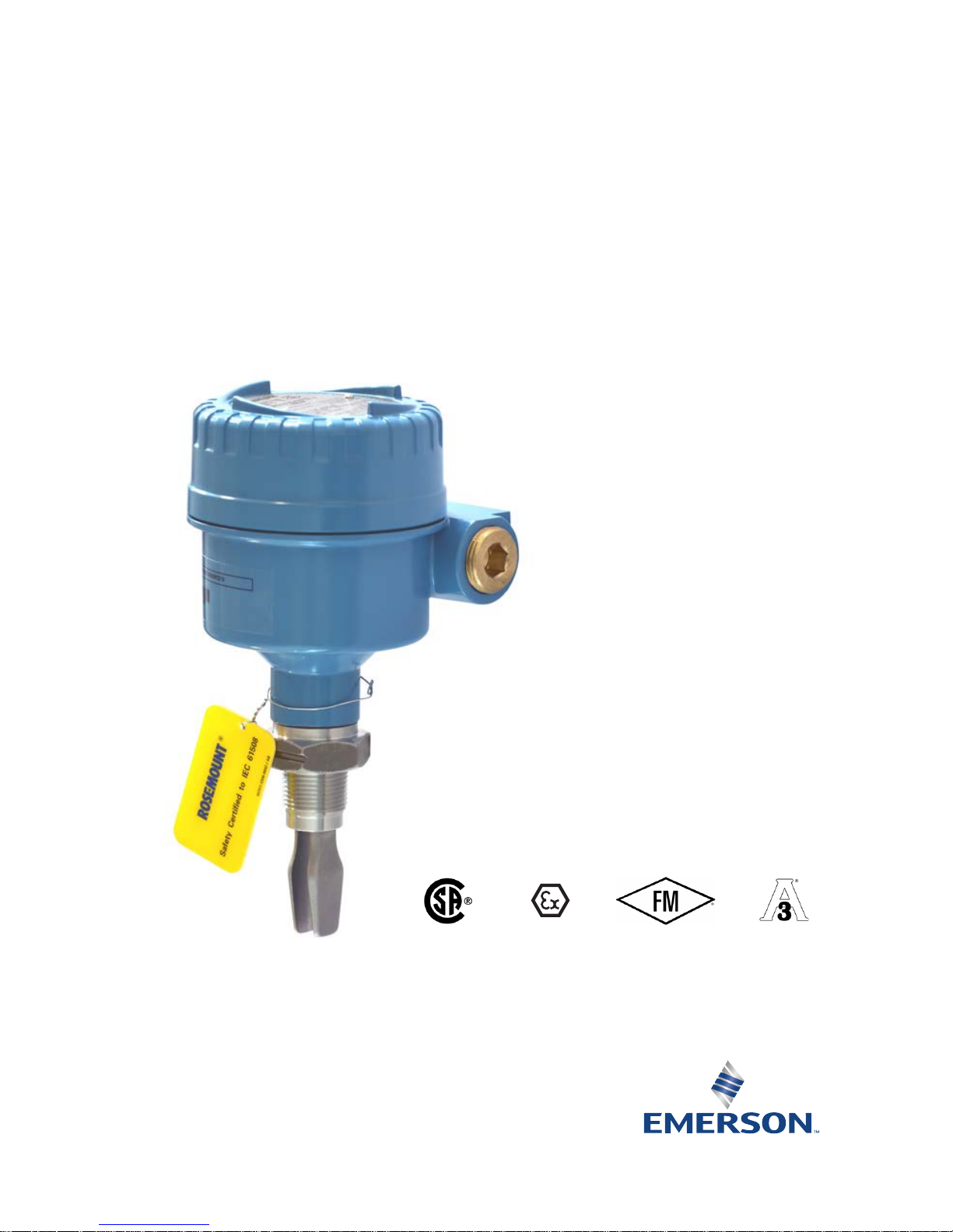
Quick Start Guide
00825-0100-4030, Rev FA
December 2016
Rosemount™ 2120 Level Switch
Vibrating Fork
Page 2

December 2016
2
Quick Start Guide
NOTICE
This guide provides basic guidelines for Rosemount 2120 Level Switch. It does not provide instructions for
configuration, diagnostics, maintenance, service, troubleshooting, or intrinsically safe (I.S.) installations.
Refer to the Rosemount 2120 Reference Manual
for more instruction. The manual and this guide are also
available electronically on Emerson.com/Rosemount
.
Failure to follow these installation guidelines could result in death or serious injury.
The Rosemount 2120 Level Switch (“level switch”) must be installed, connected, commissioned,
operated, and maintained by suitably qualified personnel only, observing any national and local
requirements that may apply.
Ensure the wiring is suitable for the electrical current and the insulation is suitable for the voltage,
temperature, and environment.
Use equipment only as specified. Failure to do so may impair the protection provided by the equipment.
Any substitution of non-recognized parts may jeopardize safety and is under no circumstances allowed.
The weight of the level switch with a heavy flange and extended fork length may exceed 37 lb (18 kg).
A risk assessment is required to be done before carrying, lifting, and installing the level switch.
Explosions could result in death or serious injury.
Installation of the level switch in a hazardous environment must be in accordance with the appropriate
local, national, and international standards, codes, and practices. Please review Product Certifications for
any restrictions associated with a safe installation.
Verify that the operating atmosphere of the level switch is consistent with the appropriate hazardous
locations certifications.
External surface may be hot.
Care must be taken to avoid possible burns.
Process leaks could result in death or serious injury.
Install and tighten process connectors before applying pressure.
Do not attempt to loosen or remove process connectors while the level switch is in service.
Electrical shock could cause death or serious injury.
If the liquid level switch is installed in a high voltage environment and a fault condition or installation error
occurs, high voltage may be present on leads and terminals.
Use extreme caution when making contact with the leads and terminals.
Make sure that power to the level switch is off while making connections.
Page 3
Quick Start Guide
3
December 2016
1.0 Introduction
1.1 Rosemount 2120 overview
The Rosemount 2120 Level Switch (“level switch”) uses vibrating short fork
technology, and is suitable for virtually all liquid applications.
The level switch is designed to use the principle of a tuning fork. A piezo-electric
crystal oscillates the forks at their natural frequency (~1400 Hz). Changes to this
frequency are continuously monitored. The frequency of the vibrating fork sensor
changes depending on the medium in which it is immersed. The denser the
liquid, the lower the frequency.
When used as a low level alarm, the liquid in the tank or pipe drains down past the
fork, causing a change of natural frequency that is detected by the electronics
and switches the output state to a dry condition. When the level switch is used as
a high level alarm, the liquid rises in the tank or pipe, making contact with the fork
which then causes the output state to switch to a wet condition.
The level switch has a ‘heartbeat’ LED that indicates its operating state. The LED
flashes when the switch output is ‘off’ and is constantly lit when 'on'.
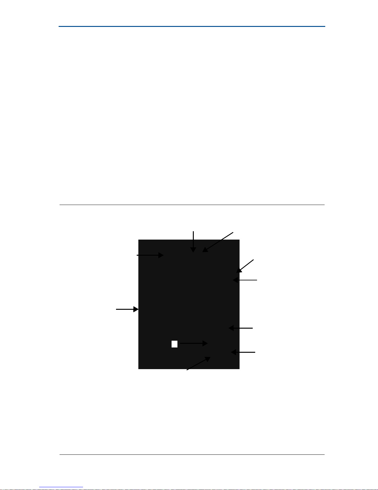
Figure 1. Rosemount 2120 Features
A. Visible ‘heartbeat’ LED G. Wetted material in 316/316L SST, solid
B. Mode switch and adjustable time delay Alloy C and Alloy C-276, or
C. Housings in glass-filled nylon, ECTFE-coated 316/316L SST
aluminum, or 316 SST H. Short fork length or extensions up to
D. Magnetic test point 157.5-in. (4 m)
E. Threaded, flanged, or hygienic connections. I. Two cable/conduit entries
F. ‘Fast drip’ fork design J. Direct Load, Relay DPCO, PLC/PNP,
NAMUR, or 8/16 mA electronics
F
B
A
G
H
C
I
J
E
D
Page 4
December 2016
4
Quick Start Guide
2.0 Before installation
2.1 General considerations
The level switch is available as intrinsically safe or explosion-proof/flameproof
versions. There are also ordinary location versions of the level switch for
unclassified, safe areas, and hygienic versions. See “Product Certifications” on
page 15 for hazardous area and hygienic installation requirements.
The weight of the Rosemount 2120 Level Switch (“level switch”) with a heavy
flange and extended fork length may exceed 37 lb. (18 kg). A risk assessment
is required to be done before carrying, lifting, and installing the level switch.
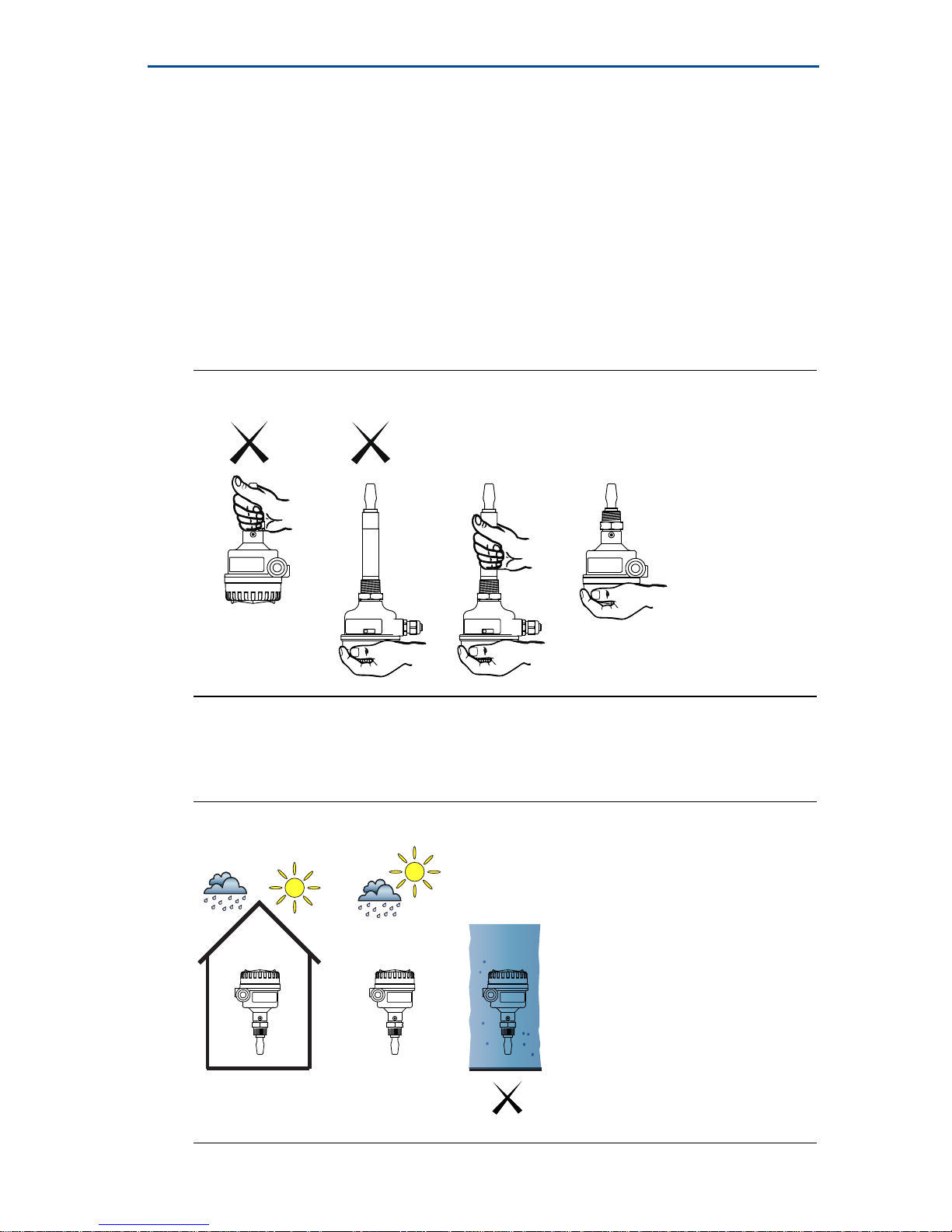
Handle the Rosemount 2120 with great care (Figure 2).
Figure 2. Handling the Rosemount 2120
This liquid level switch is designed for open or closed tanks, and pipe
installation. It is weatherproof and protected against the ingress of dust,
but must be protected from flooding (Figure 3).
Figure 3. Environmental Considerations
OK OK
OKOK
Page 5
Quick Start Guide
5
December 2016
Ensure there is adequate space outside the tank or pipe. A clearance of 1.2 in.
(30 mm) is required for the cover to be removed.
Always ensure a proper seal by installing the metal housing cover so that metal
contacts metal, or plastic contacts plastic. Use Rosemount O-rings.
Always ground the housing in accordance with national and local electrical
codes. The most effective grounding method is a direct connection to earth
(ground) with minimal impedance. Use the fork earth for metal housings with
NPT conduit entries.
2.2 Installation recommendations
Avoid installing near liquid entering the tank at the fill point.
Avoid heavy splashing on the forks.
Increasing the time delay reduces accidental switching.
Avoid installing near heat sources.
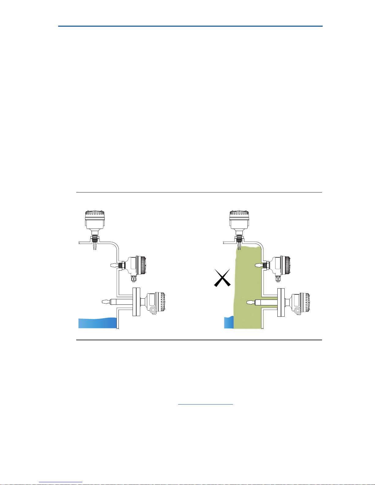
Ensure the fork does not come into contact with a tank/pipe wall or fittings.
There must be no risk of ‘bridging’ the forks (Figure 4).
Figure 4. Avoid Product Build-up
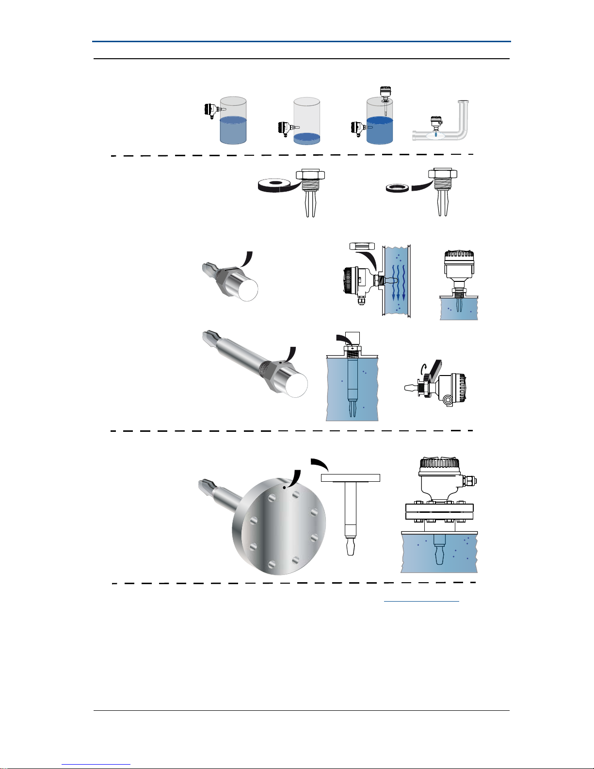
3.0 Physical installation
1. Install the level switch according to standard installation practices, making
sure to correctly align the fork using the alignment notch or groove (Figure 5).
2. Use supports for extended fork lengths greater than 3.2 ft. (1 m).
Refer to the Rosemount 2120 Reference Manual
for guidance.
3. Close the housing cover and tighten to safety specification. Always ensure a
proper seal so that metal touches metal or plastic touches plastic, but do not
over tighten.
4. Insulate the level switch with ROCKWOOL
®
. Allow 3.9 in. (100 mm) of clearance all
around the housing.
OK
Page 6
December 2016
6
Quick Start Guide
Figure 5. Example Installations
A. PTFE for NPT and BSPT (R) thread D. Fork alignment notch
B. Gasket for BSPP (G) thread E. Fork alignment notch
C. Fork alignment groove
A
E
C
B
D
Threaded
installation
Flanged
installation
D
Tri Clamp
installation
See the Rosemount 2120 Quick Release Kit Quick Start Guide
for
general Tri Clamp installation instructions.
See also “Instructions for hygienic installations” on page 26 for
hygienic installation requirements.
Page 7
Quick Start Guide
7
December 2016
4.0 Electrical installation
Before use, check that suitable cable glands and blanking plugs are fitted
and fully tightened.
Isolate supply before connecting the switch or removing the electronics.
The functional earth terminal must be connected to an external
earthing system.
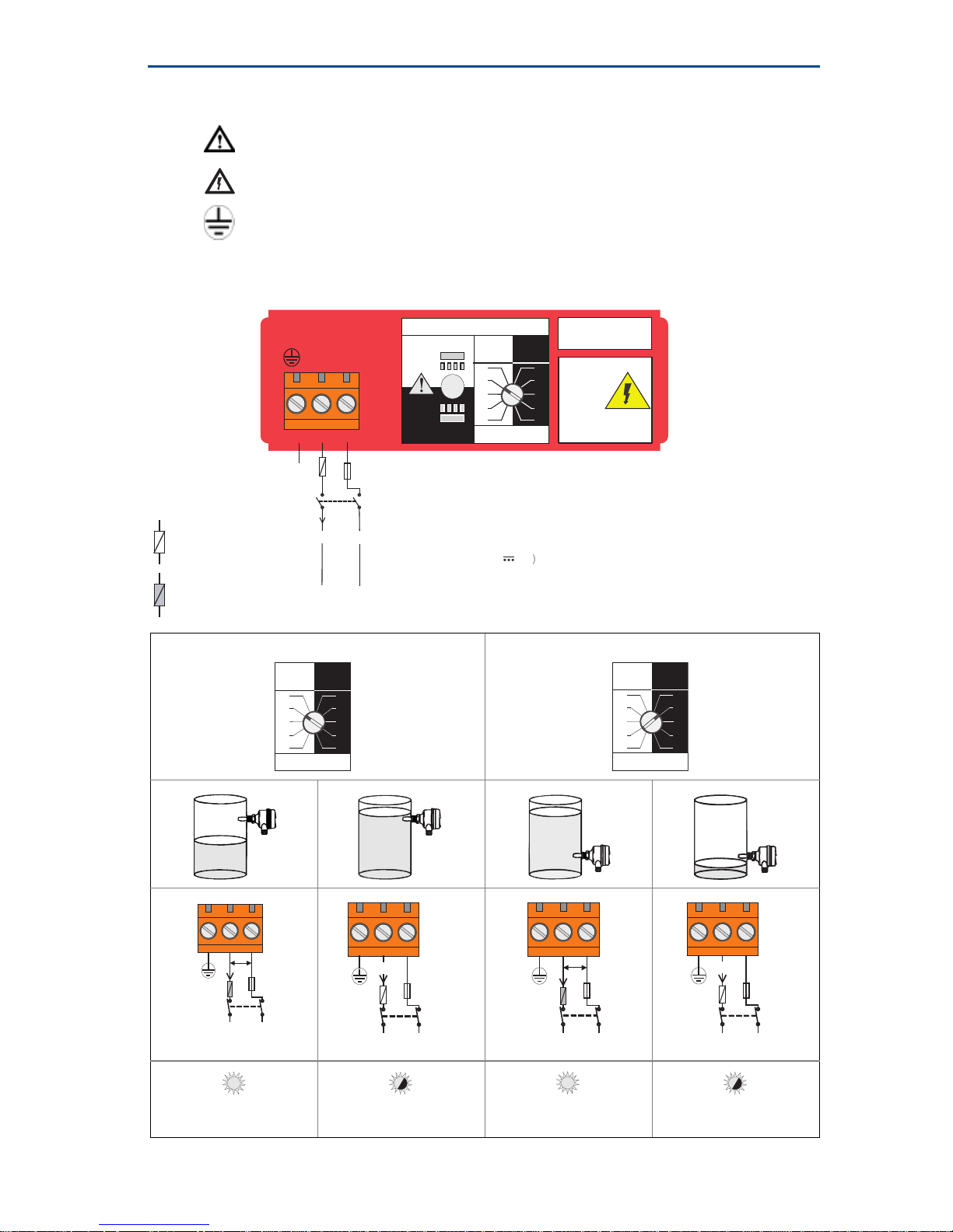
4.1 Direct load switching electronics (two-wire, red label)
High level, dry = on Low level, wet = on
LED on continuously
LED flashes each
second
LED on continuously
LED flashes each
second
Direct Load
Switching
WARNING
Isolate Supply
Before Removing
OPERATION MODE
Dry On Mode
Dry
Wet
Wet On Mode
Dry
Wet
Dry On WetOn
Seconds Delay
0.3 0.3
3
30
10
1
3
30
10
1
123
LINE
LOAD
PE
(Ground)
Neutral
Live
0V
Fuse 2A(T)
R
I
L
R = External load (must be fitted)
U = 20 - 264 V ~ (ac) (50/60Hz)
I
OFF
< 4
mA
I
L
=
20 - 500
mA
U = 20 - 60 V (dc))
I
OFF
< 4 mA
IL =
20 - 500 mA
DPST
+V
= 5 A, 40 ms (inrush)
I
PK
= 5 A, 40 ms (inrush)
I
PK
= Load On
= Load Off
Dry On Wet On
Seconds Delay
0.3 0.3
3
30
10
1
3
30
10
1
Dry On Wet On
Seconds Delay
0.3 0.3
30
10
3
30
10
1
3
1
U
N L
0V
+V
Fuse
2A(T)
I
L
12V
DPST
Fuse
2A(T)
N L
0V
+V
I
L
<4mA
DPST
U
N L
0V
+V
Fuse
2A(T)
I
L
12V
DPST
Fuse
2A(T)
N L
0V
+V
I
L
<4mA
DPST
Page 8
December 2016
8
Quick Start Guide
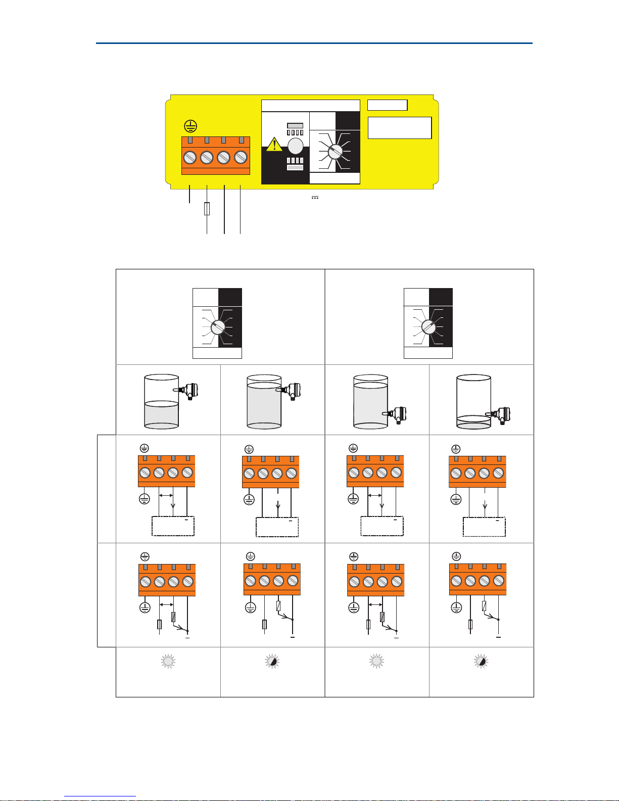
4.2 PNP/PLC switching electronics (yellow label)
High level, dry = on Low level, wet = on
PLC (positive input)PNP dc
LED on continuously
LED flashes each
second
LED on continuously
LED flashes each
second
OPERATION MODE
Dry On Mode
Dry
Wet
Wet On Mode
Dry
Wet
Dry On Wet On
Seconds Delay
0.3 0.3
3
30
10
1
3
30
10
1
12
3
OUT
+
-
4
PLC/PNP
Isolate Supply
Before Removing
PE
(Ground)
0VO/P
U = 20 - 60 V (dc)
I < 4 mA + I
L
I
L (MAX)
= 0 - 500mA
U
OUT(ON)
= U -
2.5 V
I
L (OFF)
< 100A
+V
Fuse 2A(T)
= 5 A, 40 ms (inrush)
I
PK
Dry On Wet On
Seconds Delay
0.3 0.3
3
30
10
1
3
30
10
1
Dry On Wet On
Seconds Delay
0.3 0.3
30
10
3
30
10
1
3
1
OUT
-
+
PLC
+
I/P
U
<3V
I
L
OUT
-
+
PLC
+
I/P
I
L
<100 A
OUT
-
+
PLC
+
I/P
U
<3V
I
L
OUT
-
+
PLC
+
I/P
I
L
<100 A
OUT
-
+
+
U
<3V
I
L
Fuse
1A(T)
R
OUT
-
+
+
I
L
Fuse
1A(T)
R
< 100 A
OUT
-
+
+
U
<3V
I
L
Fuse
1A(T)
R
OUT
-
+
+
I
L
Fuse
1A(T)
R
< 100 A
Page 9
Quick Start Guide
9
December 2016
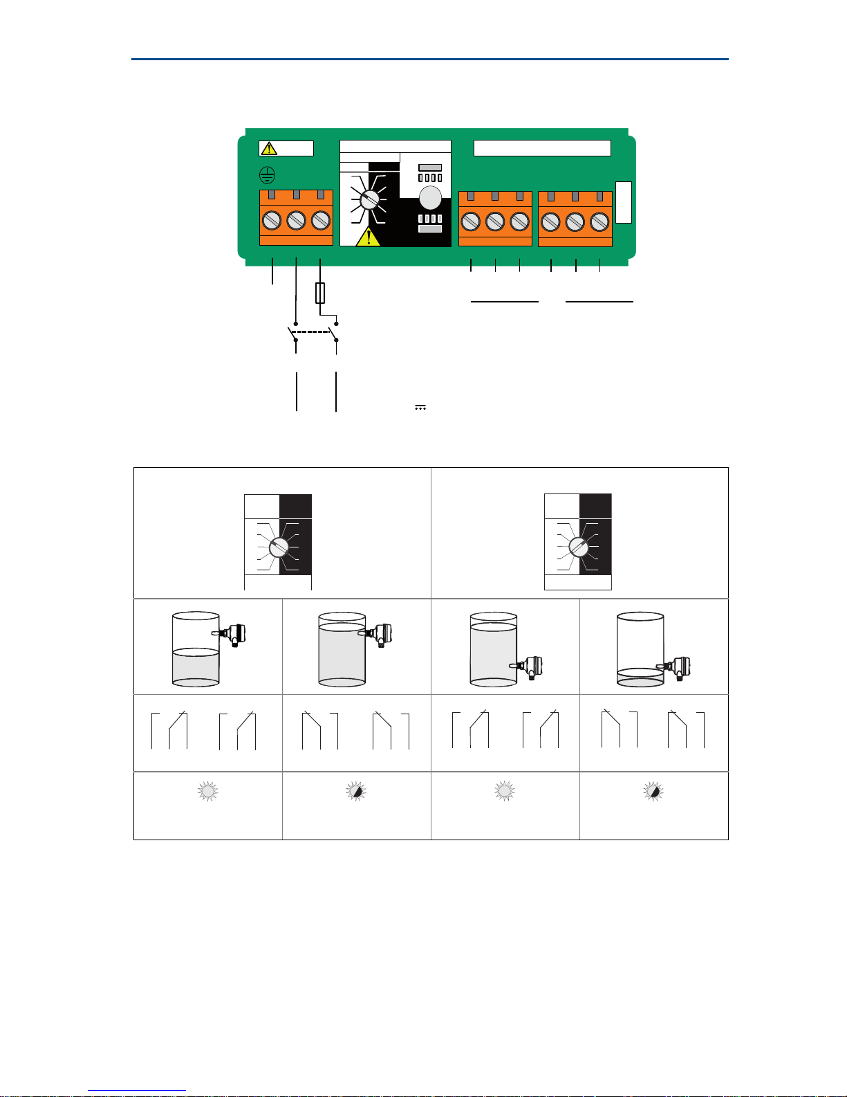
4.3 DPCO relay output electronics
(green label, standard version)
High level, dry = on Low level, wet = on
LED on continuously
LED flashes each
second
LED on continuously
LED flashes each
second
NC
C
NO
NC NO
789
NOCNC
RELAY
123
LN
45
6
NOCNC
OPERATION MODE
Dry On
Dry
Wet
Wet On
Dry
Wet
Dry On
Wet On
Second s D el ay
30
10
3
1
0.3 0.3
30
10
3
1
Isolate Supply Be fore Rem oving
Warning
C
Resistive Load
cos φ = 1 ;
L/R = 0 ms
ac
dc
Inductive Load
Fuse 0.5 (T)PE
(Ground)
DPST
N
0V +V
Live
U = 20...264 V ~ (ac)
(50/60 Hz)
U = 20...60 V (dc)
I < 6 mA
I < 6 mA
I
MAX
= 5 A
U
MAX
= 250 V
P
MAX
= 1250 VA
U
MAX
= 30 V
P
MAX
= 240 W
cos φ = 0.4 ;
L/R = 7 ms
ac
dc
I
MAX
= 3.5 A
U
MAX
= 250 V
P
MAX
= 875 VA
U
MAX
= 30 V
P
MAX
= 170 W
Dry On Wet On
Seconds Delay
0.3 0.3
3
30
10
1
3
30
10
1
Dry On Wet On
Seconds Delay
0.3 0.3
30
10
3
30
10
1
3
1
NC NOC
NC NOC
NC NOC
NC NOC
NC NOC
NC NOC
NC NOC
NC NOC
Page 10
December 2016
10
Quick Start Guide
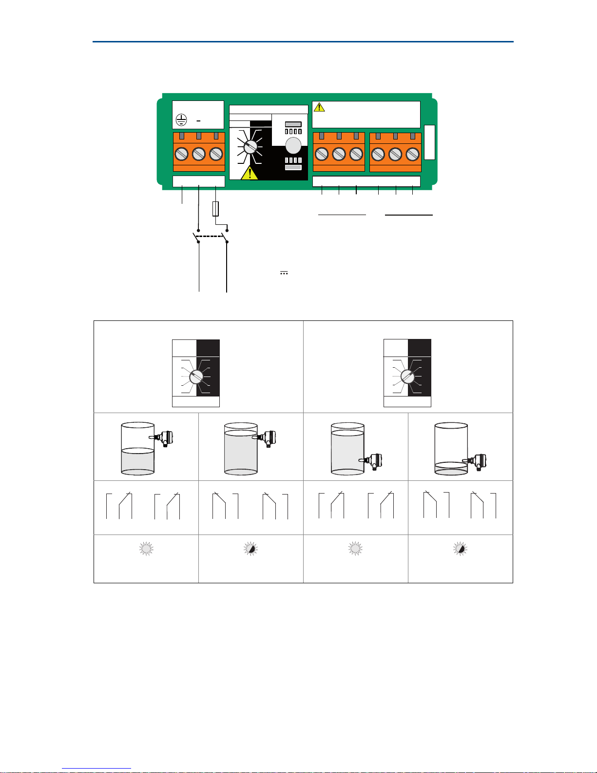
4.4 DPCO relay output electronics
(green label, 12 Vdc nominal version)
High level Dry = ON Low level wet = ON
LED on continuously
LED flashes each
second
LED on continuously
LED flashes each
second
NC
C
NO
NC NO
789
NOCNC
RELAY
123
+
45
6
NOCNC
OPERATION MODE
Dry On
Dry
Wet
Wet On
Dry
Wet
Dry On
Wet On
Second s D el ay
30
10
3
1
0.3 0.3
30
10
3
1
Isolate Supply Be fore Removing12 VDC NOM.
C
Resistive Load
cos φ = 1 ;
L/R = 0 ms
ac:
dc:
Inductive Load
Fuse 0.5 (T)PE
(Ground)
DPST
0V +V
U = 9...30 V (dc)
I < 4 mA
I
MAX
= 2 A
U
MAX
= 125 V
P
MAX
= 62.5 VA
U
MAX
= 30 V
P
MAX
= 60 W
cos φ = 0.4 ;
L/R = 7 ms
ac:
dc:
I
MAX
= 1 A
U
MAX
= 125 V
P
MAX
= 37.5 VA
U
MAX
= 30 V
P
MAX
= 30 W
Dry On Wet On
Seconds Delay
0.3 0.3
3
30
10
1
3
30
10
1
Dry On Wet On
Seconds Delay
0.3 0.3
30
10
3
30
10
1
3
1
NC NOC
NC NOC
NC NOC
NC NOC
NC NOC
NC NOC
NC NOC
NC NOC
Page 11
Quick Start Guide
11
December 2016
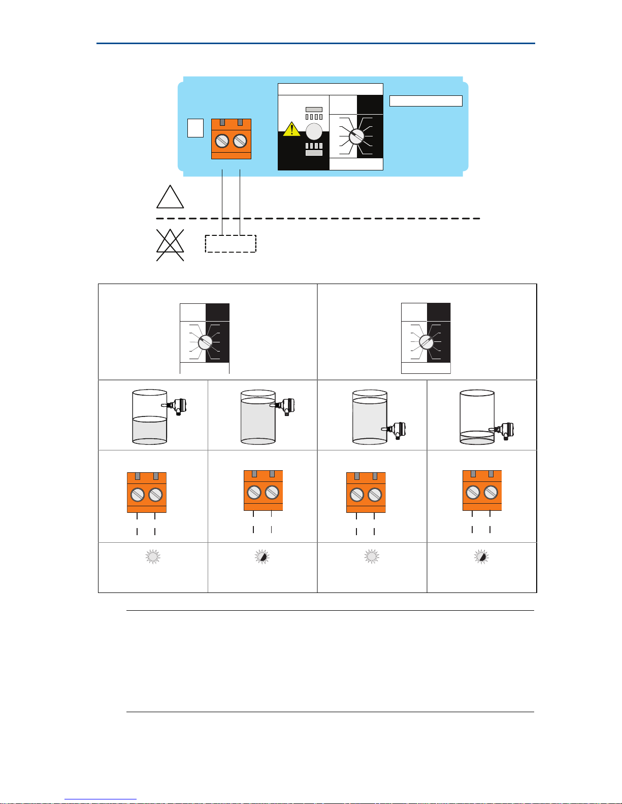
4.5 NAMUR electronics (light blue label)
Note
This cassette is suitable for Intrinsically Safe applications and requires an isolating
barrier. See “Product Certifications” on page 15 for Intrinsically Safe approvals.
This electronics cassette is also suitable for non-hazardous (safe) area
applications. It can only be interchanged with the 8/16 mA cassette.
Do not exceed 8 Vdc.
High level, dry = on Low level, wet = on
LED on continuously
LED flashes each
second
LED on continuously
LED flashes each
second
OPERATION MODE
Dry On Mode
Dry
Wet
Wet O n Mo d e
Dry
Wet
Dry On Wet On
Seconds Delay
0.3 0.3
3
30
10
1
3
30
10
1
12
+-
EN 50227 / NAMUR
ION= 2.2 ... 2.5 mA
I
OFF
I
FAULT
= 0.8 .. . 1.0 mA
+
-
A certified intrinsically safe
isolat ing am plifier to IEC 60947-5-6
Ex
Ex
8V
dc
< 1.0 mA
Dry On Wet On
Seconds Delay
0.3 0.3
3
30
10
1
3
30
10
1
Dry On Wet On
Seconds Delay
0.3 0.3
30
10
3
30
10
1
3
1
+
-
>2.2 mA
+
-
<1.0 mA
+
-
>2.2 mA
+
-
<1.0 mA
Page 12
December 2016
12
Quick Start Guide
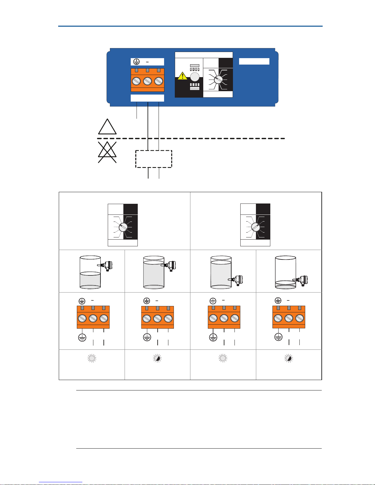
4.6 8/16 mA electronics cassette (dark blue label)
Note
This cassette is suitable for Intrinsically Safe applications and requires an isolating
barrier.
See “Product Certifications” on page 15 for Intrinsically Safe approvals.
This cassette is also suitable for non-hazardous (safe) area applications. It can only
be interchanged with a NAMUR cassette.
High level, dry = on Low level, wet = on
LED on continuously
LED flashes each
second
LED on continuously
LED flashes each
second
OPERATION MODE
Dry On Mode
Dry
Wet
Wet On Mode
Dry
Wet
Dry On Wet On
Seconds Delay
0.3 0.3
3
30
10
1
3
30
10
1
8/16 mA
12
3
+
Drives 4-20 mA Analog Input
I
ON
=
I
OFF
=
+
-
+
A certified intrinsically safe barrier
must be used to meet IS requirements
Ex
Ex
15 ... 17 mA
7.5 ... 8.5 mA
-
PE
(Ground)
U
=
24 Vdc Nominal
I
FAULT
< 3.7 mA
Dry On Wet On
Seconds Delay
0.3 0.3
3
30
10
1
3
30
10
1
Dry On Wet On
Seconds Delay
0.3 0.3
30
10
3
30
10
1
3
1
+
> 15 mA
+
< 8.5 mA
+
> 15 mA
+
< 8.5 mA
Page 13
Quick Start Guide
13
December 2016
5.0 Configuration
Note
Recommended installation for a high level alarm is “Dry on” and for a low level
alarm it is “Wet on”. Do not install in the normally ‘off’ state.
Set mode switch and switching time delay
1. Select “Dry on” or “Wet on” mode.
2. Select 0.3, 1, 3, 10, or 30 seconds for the delay before switching output state.
(There is an initial five second delay when changing mode or time delay).
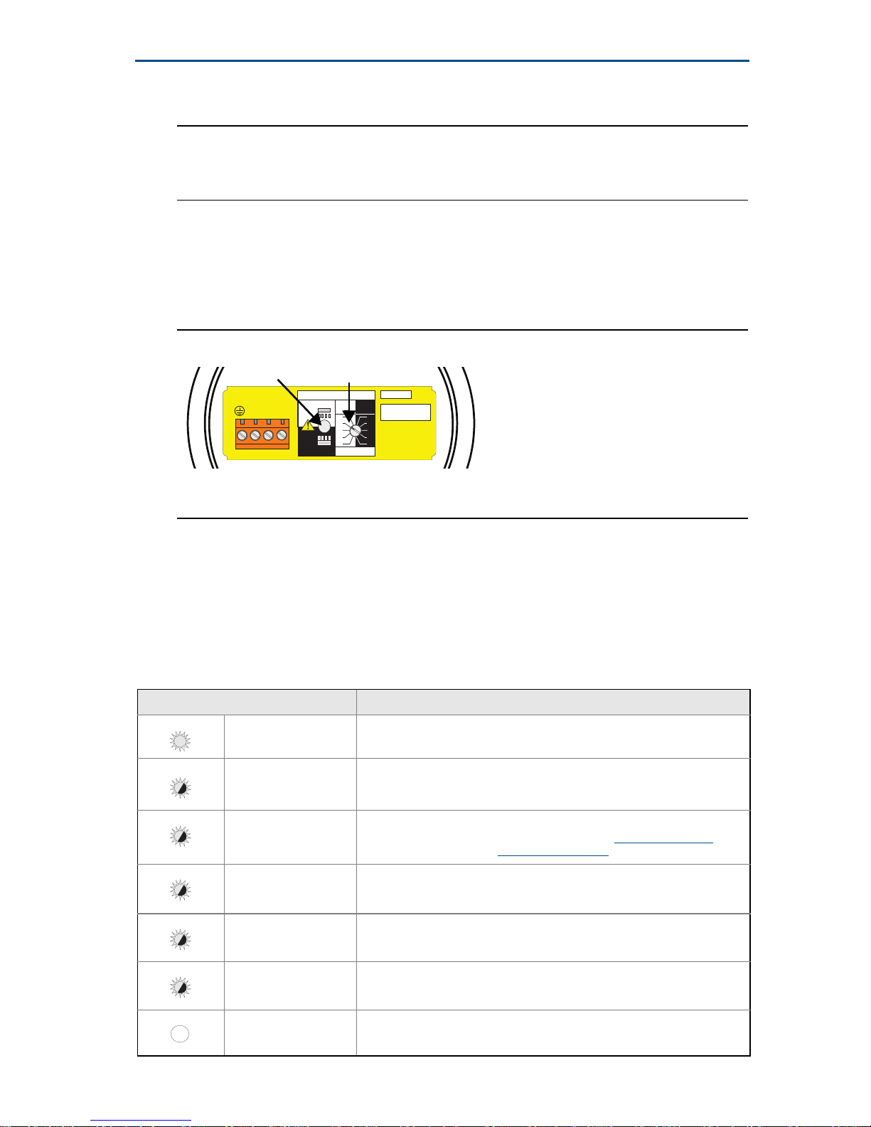
Figure 6. Top-down View of Example Cassette Inside Housing
A. LED
B. Mode Switch and Time Delay
6.0 Verify operation
6.1 LED indication
See Table 1 for the LED indications.
Table 1. LED Flash Rate
LED flash rate Switch status
Continuous Output state is on
1 every second Output state is off
1 every 2 seconds
Uncalibrated: Refer to the “Replacement and Calibration of Electronic
Cassettes” section in the Rosemount 2120 Reference Manual
or
Manual Supplement
1 every 4 seconds Load fault; load current too high; load short circuit
2 times every second Indication of successful calibration
3 times every second Internal PCB fault (microprocessor, ROM, or RAM)
Off Problem (e.g. supply)
OPERATION MODE
Dry On Mode
Dry
Wet
Wet On Mode
Dry
Wet
Dry On Wet On
Seconds Delay
0.3 0.3
3
30
10
1
3
30
10
1
12
3
OUT
+
-
4
PLC/PNP
Isolate Supply
Before Removing
B
A
Page 14
December 2016
14
Quick Start Guide
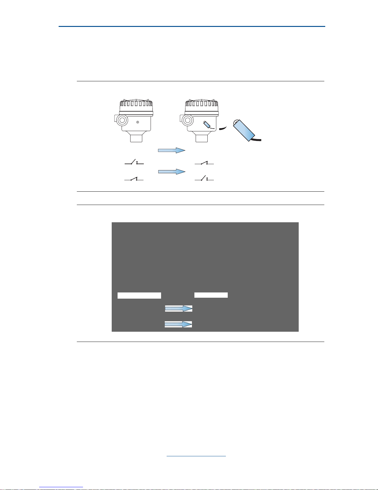
6.2 Magnetic test point
The magnetic test-point is on the side of the housing, allowing a functional test of
the level switch. By touching a magnet on the target, the output will change state
for as long as the magnet is held there.
Figure 7. Magnetic Test Point (Metal Housing)
Figure 8. Magnetic Test Point (Glass-filled Nylon Housing)
7.0 Maintenance and inspection
Only use a damp cloth for cleaning.
Visually examine the level switch for damage. If it is damaged, do not use.
Ensure the housing cover, cable glands, and blanking plugs are fitted securely.
Ensure the LED flash rate is 1 Hz or continually on.
(See “LED indication” on page 13).
8.0 Spare parts
See the Rosemount 2120 Product Data Sheet for spares and accessories.
TP
TP
TP
S
N
S
N
(Output on)
(Output on)
(Output off)
(Output off)
No Magnet
Magnet
(Output on)
(Output on)
(Output off)
(Output off)
No Magnet
Magnet
Page 15
Quick Start Guide
15
December 2016
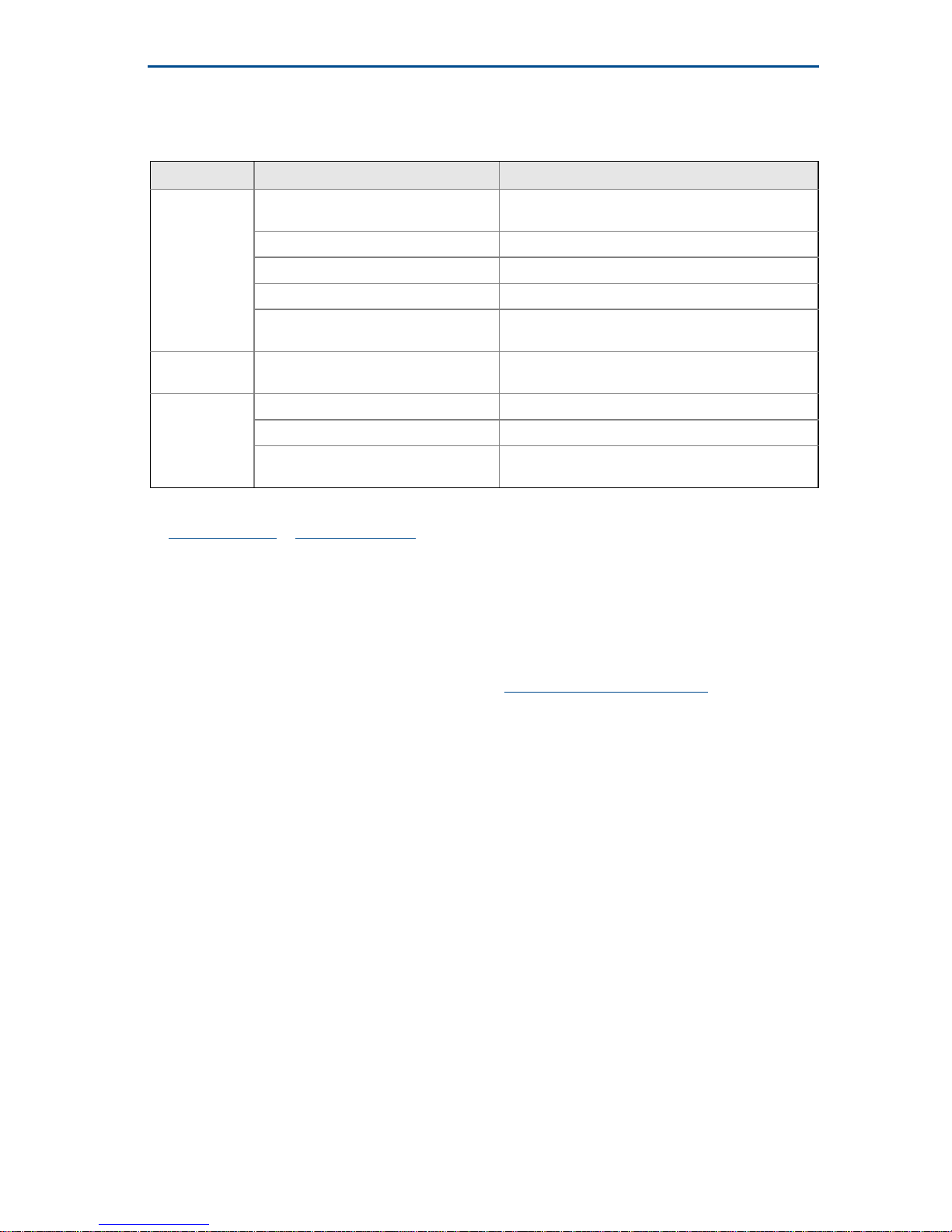
9.0 Troubleshooting
Table 2. Troubleshooting Chart
10.0 Product Certifications
10.1 European Union directive information
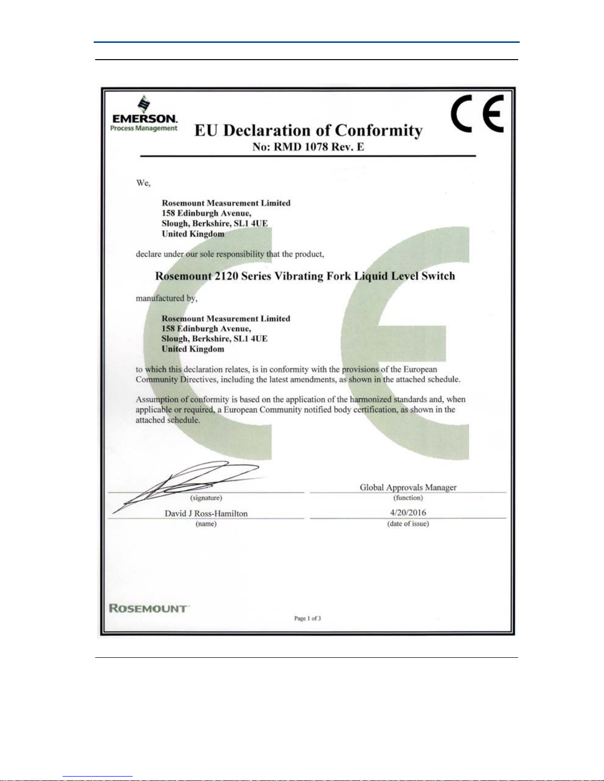
The EC declaration of conformity for all applicable European directives for this
product can be found on page 28 and at Emerson.com/Rosemount.
10.2 Hygienic approvals and compliance
3-A® (authorization 3496), and EHEDG (certificate: 102016)
ASME-BPE and FDA compliant
(See “Instructions for hygienic installations” on page 26)
10.3 Overfill approval
Certificate number: Z-65.11-522.
TÜV-tested and approved for overfill protection according to the German
DIBt/WHG regulations. Certified under safety devices for tanks and piping related
to water pollution control.
10.4 Marine approvals
ABS – American Bureau of Shipping
GL – Germanischer Lloyd
SRS – Russian Maritime Registered Shipping (RMRS)
10.5 NAMUR approval
NAMUR NE95 type test is available upon request. Complies with NAMUR NE21.
Fault Symptom and indication Action and solution
Does not
switch
No LED; no power
Check the power supply; (check load on direct load
switching electronics model)
LED flashing See “LED indication” on page 13
Fork is damaged Replace the Rosemount 2120
Thick encrustation on the forks Clean the fork with care
5 second delay when changing
mode/delay
This is normal – wait 5 seconds
Incorrect
switching
Dry = On, Wet = On set correctly Set the correct mode on the electronics cassette
Faulty
switching
Turbulence Set a longer switching time delay
Excessive electrical noise Suppress the cause of the interference
Cassette has been fitted from another
Rosemount 2120
Fit the factory supplied cassette and then
calibrate
(1)
1. Refer to the “Replacement and Calibration of Electronic Cassettes” section in the Rosemount 2120
Reference Manual
or Manual Supplement.
Page 16

December 2016
16
Quick Start Guide
10.6 Drinking water approval
Rosemount Measurement Limited, Slough, UK confirms that the wetted parts of
the Rosemount 2120 Vibrating Liquid Level Switches are suitable and approved
for use in potable water.
The wetted parts of the vibrating level switches executed in:
Stainless steel (option code D) and Alloy C / Alloy C-276 (option code C) with
Flanged, NPT thread, BSPT(R) thread, or Tri Clamp process connections, are in
accordance with the requirements of DVGW - Worksheet W270.The materials
used are classified as toxicologically and microbiologically safe.
10.7 Ordinary location certifications
Ordinary location certification for FM
G5 Project ID: 3021776
The switch has been examined and tested to determine that the design meets
basic electrical, mechanical, and fire protection requirements by FM, a
nationally recognized testing laboratory (NRTL) as accredited by the Federal
Occupational Safety and Health Administration (OSHA).
Ordinary location certification for CSA
G6 Certificate Number: 06 CSA 1805769
The switch has been examined and tested to determine that the design meets
basic electrical, mechanical, and fire protection requirements by CSA, a
nationally recognized testing laboratory as accredited by the Standards
Council of Canada (SCC). Single seal.
10.8 Canadian Registration Number
Certificate number: CRN 0F04227.2C
The requirements of CRN are met when a Rosemount 2120 CSA-approved
vibrating fork level switch model is configured with 316/316L stainless steel
(1.4401/1.4404) process-wetted parts and either NPT threaded or 2 to 8-in.
ASME B16.5 flanged process connections.
10.9 Safety Integrity Level (SIL) certification
The Rosemount 2120 has been independently certified to IEC 61508 as required
by IEC 61511. Certification was conducted by Exida.
The Rosemount 2120 is SIL2-certified, and is SIL3 capable.
10.10 Hazardous locations certifications
Note
A certified isolating amplifier to IEC 60947-5-6 is required for intrinsic safety if the
NAMUR electronics is used in a hazardous area installation
A certified intrinsically safe barrier is required for intrinsic safety if the 8/16 mA
electronics is used in a hazardous area installation
Page 17

Quick Start Guide
17
December 2016
North American and Canadian approvals
Factory Mutual (FM) explosion-proof approval
(See “Instructions for hazardous area installations (E5 and E6)” on page 18)
E5 Project ID: 3012658
Explosion-proof for Class I, Div. 1, Groups A, B, C, and D
Temperature Class: T6 (T
amb
–40 to 75 °C)
Enclosure: Type 4X
Factory Mutual (FM) intrinsically safe and non-incendive approvals
(See “Instructions for hazardous area installations (I5 and I6)” on page 20)
I5 Project ID: 3011456
Intrinsically safe for:
Class I, Div. 1, Groups A, B, C, and D; Class I, Zone 0, AEx ia IIC
Nonincendive for: Class I, Div. 2, Groups A, B, C and D; Class I, Zone 2, IIC
Temperature Code: T5 (T
amb
–40 to 80 °C, T
proc
< 80 °C)
Control Drawing: 71097/1154 (with NAMUR electronics)
Control Drawing: 71097/1314 (with 8/16 mA electronics)
Canadian Standards Association (CSA) explosion-proof approval
(See “Instructions for hazardous area installations (E5 and E6)” on page 18)
E6 Project ID: 1786345
Explosion-proof for Class I, Div. 1, Groups A, B, C, and D
Temperature Class: T6 (T
amb
–40 to 75 °C)
Enclosure: Type 4X
Single process seal
Canadian Standards Association (CSA)
intrinsically safe and non-incendive approvals
(See “Instructions for hazardous area installations (I5 and I6)” on page 20)
I6 Certificate Number: 06 CSA 1786345
Intrinsically safe for:
Class I, Div. 1, Groups A, B, C, and D; Class I, Zone 0, Ex ia IIC
Non-Incendive for: Class I, Div. 2, Groups A, B, C, and D
Temperature Code: T5 (T
amb
–40 to 80 °C, T
proc
< 80 °C)
Control Drawing: 71097/1179 (with NAMUR electronics)
Control Drawing: 71097/1315 (with 8/16 mA electronics)
Single process seal
European approvals
ATEX approvals
E1 Certificate: Sira 05ATEX1129X
Flameproof and dust-proof:
ATEX Marking II 1/2 GD
Ex db IIC T6...T2 Ga/Gb, Ex tb IIIC T85 °C...T265 °C Db
(See “Instructions for hazardous area installations (E1 and E7)” on page 22)
Page 18

December 2016
18
Quick Start Guide
I1 Certificate: Sira 05ATEX2130X
Intrinsically Safe for gas and dust environments:
ATEX Marking II 1 G D
Ex ia IIC T5...T2 Ga, Ex ia IIIC T85 °C...T265 °C Da
(See “Instructions for hazardous area installations (I1 and I7)” on page 24)
International approvals
International Electrotechnical Commission (IEC) approvals
E7 Certificate: IECEx SIR 06.0051X
Flameproof and dust-proof:
Ex db IIC T6...T2 Ga/Gb, Ex tb IIIC T85 °C...T265 °C Db
(See “Instructions for hazardous area installations (E1 and E7)” on page 22)
I7 Certificate: IECEx SIR 06.0070X
Intrinsically safe for gas and dust environments:
Ex ia IIC T5...T2 Ga, Ex ia IIIC T85 °C...T265 °C Da
(See “Instructions for hazardous area installations (I1 and I7)” on page 24)
Technical Regulation Customs Union (EAC) approvals
EM Certificate: TC RU C-GB.BH02.B.00175
Flameproof:
1Exd IIC T6...T3 X
Ta (see table in the certificate)
IM Certificate: TC RU C-GB.BH02.B.00175
Intrinsic Safety:
0Exia IIC T5...T3 X
Ta (see table in the certificate)
10.11 Instructions for hazardous area installations (E5 and E6)
Model numbers covered:
2120*****E5Y**, 2120*****E5T**, 2120*****E6Y**, 2120*****E6T**
(“*” indicates options in construction, function and materials).
The following instructions apply to equipment covered by CSA and FM
explosion-proof approvals:
1. The equipment may be used with flammable gases and vapors with apparatus
Class 1, Div 1, Groups A, B, C and D.
2. CSA and FM Explosion Proof approved versions of the 2120 are certified for
use in ambient temperatures of –40 °F to 176 °F (–40 °C to 80 °C), and with a
maximum process temperature of 302 °F (150 °C).
3. Installation of this equipment shall be carried out by suitably trained
personnel, in accordance with the applicable code of practice.
4. Inspection and maintenance of this equipment shall be carried out by suitably
trained personnel, in accordance with the applicable code of practice.
5. The user should not repair this equipment.
6. The certification of this equipment relies upon the following materials used in
its construction:
Body: Aluminum Alloy (ASTM B85 360.0) or 316 SST
Page 19

Quick Start Guide
19
December 2016
Lid: Aluminum Alloy (ASTM B85 360.0) or 316 SST
Probe:
316 Stainless Steel, or Alloy C276 (UNS N10276) and Alloy C (UNS N10002)
Probe filling: Perlite
Lid seal: Silicone
If the equipment is likely to come into contact with aggressive substances, it is
the responsibility of the user to take suitable precautions that prevent it from
being adversely affected, thus ensuring that the type of protection is not
compromised.
Aggressive substances – e.g. acidic liquids or gases that may attack metals or
solvents that may affect polymeric materials.
Suitable precautions – e.g. regular checks as part of routine inspections or
establishing from the material’s data sheet that it is resistant to specific
chemicals.
The metallic alloy used for the enclosure material may be at the accessible
surface of this equipment; in the event of rare accidents, ignition sources due
to impact and friction sparks could occur. This shall be considered when the
level switch is installed in locations that specifically require Class 1, Div 1
equipment.
7. It is the responsibility of the user to ensure:
a. The voltage and current limits for this equipment are not exceeded.
b. That the joint requirements between the switch and the vessel tank are
compatible with the process media.
c. That the joint tightness is correct for the joint material used.
d. That only certified cable entry devices will be used when connecting this
equipment.
e. That any unused cable entries are sealed with suitably certified stopping
plugs.
8. The switch fork is subjected to small vibration stresses as part of its normal
function. As this provides a partition wall, it is recommended that the fork
should be inspected every 2 years for signs of defects.
9. Technical data:
a. Coding: Class 1, Div 1, Groups A, B, C, and D
b. Temperature:
2120*****E5Y**, 2120*****E5T**, 2120*****E6Y**, 2120*****E6T**:
Minimum ambient air temperature (Ta) = –40 °C
Minimum process temperature (Tp) = –40 °C
Temperature
classes
Maximum ambient air
temperature (Ta)
Maximum process
temperature (Tp)
T6, T5, T4, T3, T2, T1 75 °C 75 °C
T5, T4, T3, T2, T1 70 °C 95 °C
T4, T3, T2, T1 65 °C 125 °C
T3, T2, T1 50 °C 150 °C
Page 20
December 2016
20
Quick Start Guide
c. Pressure: Must not exceed the rating of the coupling/flange fitted.
d. For electrical details and pressure ratings, see the Rosemount 2120
Product Data Sheet or Reference Manual.
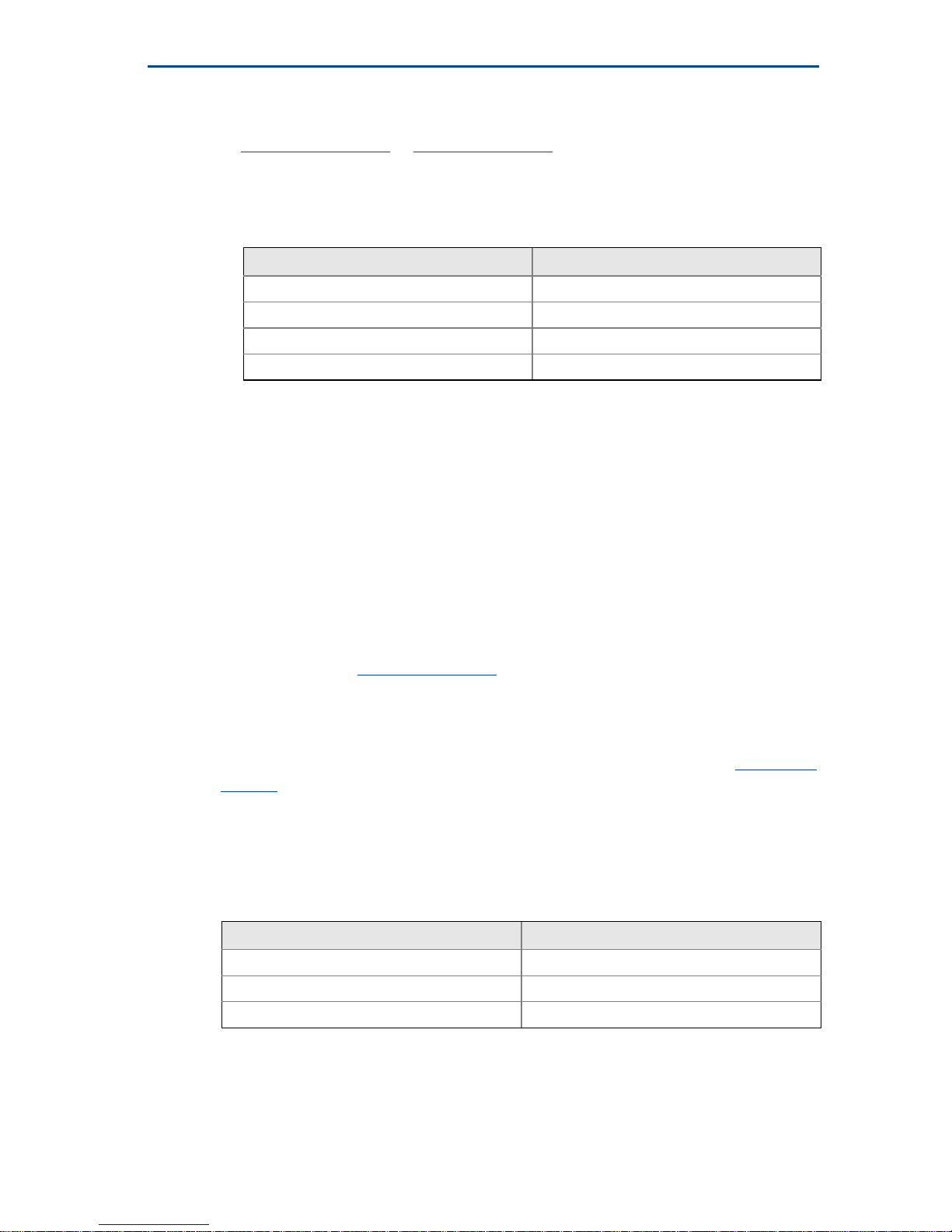
10. Cable selection:
a. It is the responsibility of the user to ensure that suitably temperature rated
cable is used. The table below is a guide to selection:
10.12 Instructions for hazardous area installations (I5 and I6)
Model numbers covered:
2120***H*I5A*, 2120***K*I5D*,
2120***H*I6A*, 2120***K*I6D*
(“*” indicates options in construction, function and materials.)
The following instructions apply to equipment covered by FM and CSA approvals:
1. The intrinsically safe approved Rosemount 2120 may be used in hazardous
locations with flammable gases and vapors Class 1 Division 1 Groups A, B, C,
and D, and Class 1 Zone 0 Group IIC when installed in accordance with control
drawings 71097/1154, 71097/1314, 71097/1179, or 71097/1315 in the
Rosemount 2120 Reference Manual
.
2. The non-incendive approved Rosemount 2120 may be used in hazardous
locations with flammable gases and vapors Class 1 Division 2 Groups A, B, C,
and D when installed in accordance with control drawings 71097/1154,
71097/1314, 71097/1179, or 71097/1315 in the Rosemount 2120 Reference
Manual.
3. The apparatus electronics is only certified for use in ambient temperatures in
the range of -40 °C to +80 °C. It should not be used outside this range.
However, the switch may be located in the process medium which may be at a
higher temperature than the electronics but must not be higher than the
Temperature Class for the respective process gas/medium.
It is a condition of the approval that the temperature of the electronics
housing is in the range of -40 °F to +176 °F (-40 to +80 °C). It must not be used
outside this range. It will be necessary to limit the external ambient
temperature if the process temperature is high. (See “Technical data” below.)
T class Cable temperature rating
T6 Above 185 °F (85 °C)
T5 Above 212 °F (100 °C)
T4 Above 275 °F (135 °C)
T3 Above 320 °F (160 °C)
Process Temperature Temperature classes
176 °F (80 °C) T1, T2, T3, T4, T5
239 °F (115 °C) T1, T2, T3, T4
302 °F (150 °C) T1, T2, T3
Page 21

Quick Start Guide
21
December 2016
4. Suitably trained personnel shall carry out installation in accordance with the
applicable code of practice.
5. The user should not repair this equipment.
6. If the equipment is likely to come into contact with aggressive substances, it is
the responsibility of the user to take suitable precautions that prevent it from
being adversely affected, thus ensuring that the type of protection is not
compromised.
Aggressive substances – e.g. acidic liquids or gases that may attack metals or
solvents that may affect polymeric materials.
Suitable precautions – e.g. regular checks as part of routine inspections or
establishing from the material’s data sheet that it is resistant to specific
chemicals
7. If the enclosure is made of an alloy or plastic material, the following
precautions must be observed:
a. The metallic alloy used for the enclosure material may be at the accessible
surface of this equipment; in the event of rare accidents, ignition sources
due to impact and friction sparks could occur
b. Under certain extreme circumstances, the non-metallic parts incorporated
in the enclosure of the Rosemount 2120 may generate an ignition-capable
level of electrostatic charge. Therefore, when they are used for applications
that specifically require group II equipment, the Rosemount 2120 shall not
be installed in a location where the external conditions are conducive to the
build-up of electrostatic charge on such surfaces. Additionally, the
Rosemount 2120 shall only be cleaned with a damp cloth.
8. Technical data:
a. I.S. approval: Class 1 Division 1 Groups ABC and D, Class 1 Zone 0 AEx ia IIC
Non-Incendive Approval: Class 1 Division 2 Groups ABC and D
T5 (Ta = -40 °F to +176 °F [-40 °C to +80 °C])
T4 (Ta = -40 °F to +239 °F [-40 °C to +115 °C])
T3 (Ta = -40 °F to +302 °F [-40 °C to +150 °C])
Ta = the higher of the process or ambient temperature.
b. Input parameters:
Rosemount 2120 with NAMUR electronics:
Vmax=15 V, Imax=32 mA, Pi=0.1 W, Ci=211 nF, Li=0.06 mH
Rosemount 2120 with 8/16 mA electronics:
Vmax=30 V, Imax=93 mA, Pi=0.65 W, Ci=12 nF, Li=0.035 mH
c. Temperature:
Process (Tp) -40 °C to 150 °C
External (Ta) -40 °C to +80 °C
(up to Tp=80 °C, reducing linearly to 50 °C at Tp=150 °C)
d. Materials:
See the Rosemount 2120 Product Data Sheet
or Reference Manual.
Page 22

December 2016
22
Quick Start Guide
10.13 Instructions for hazardous area installations (E1 and E7)
Model numbers covered:
2120*****E1X**, 2120*****E1S**, 2120*****E7X**, 2120*****E7S**
(“*” indicates options in construction, function and materials.)
The following instructions apply to the equipment covered by certificates
numbered
Sira 05ATEX1129X and IECEx SIR 06.0051X:
1. The equipment may be used with flammable gases and vapors with apparatus
groups IIA, IIB, and IIC, and with temperature classes T1, T2, T3, T4, T5, and
T6. The temperature class of the installation will be determined from the
higher of the process or ambient temperature.
2. The equipment may be used in a hazardous area with explosive dusts with
apparatus groups IIIC, IIIB, and IIIA. The maximum surface temperature of the
installation will be determined from the higher of the process or ambient
temperature.
3. The equipment is suitable for installation across the boundary between an
area that specifically requires Equipment Protection Level Ga (Zone 0) and an
area that specifically requires Equipment Protection Level Gb or Db (Zone 1 or
21). The probe forks (and extension tube) only to be installed in Zone 0.
4. The equipment has not been assessed as a safety related device (as referred to
by Directive 94/9/EC (2014/34/EU) Annex II, clause 1.5).
5. Installation of this equipment shall be carried out by suitably trained
personnel, in accordance with the applicable code of practice.
6. Inspection and maintenance of this equipment shall be carried out by suitably
trained personnel, in accordance with the applicable code of practice.
7. The user should not repair this equipment. Repair or modification of
flame-paths is not permitted.
8. The certification of this equipment relies upon the following materials used in
its construction:
Housing and cover:
Aluminum alloy (ASTM B85 360.0) or stainless steel 316C12
Probe (partition wall): Stainless steel 316L or 316/316L, or
Alloy C276 (UNS N10276) and Alloy C (UNS N10002 or N30002)
Probe filling: Perlite
Lid seal: Silicone
If the equipment is likely to come into contact with aggressive substances, it is
the responsibility of the user to take suitable precautions that prevent it from
being adversely affected, thus ensuring that the type of protection is not
compromised.
Aggressive substances: e.g. acidic liquids or gases that may attack metals, or
solvents that may affect polymeric materials.
Suitable precautions: e.g. regular checks as part of routine inspections or
establishing from the material’s data sheet that it is resistant to specific
chemicals.
Page 23
Quick Start Guide
23
December 2016
9. It is the responsibility of the user to ensure:
a. The voltage and current limits for this equipment are not exceeded.
b. That the joint requirements between the probe and the vessel tank are
compatible with the process media.
c. That the joint tightness is correct for the joint material used.
d. That only suitably certified cable entry devices will be utilized when
connecting this equipment.
e. That any unused cable entries are sealed with suitably certified stopping
plugs.
10. The probe fork is subjected to small vibration stresses as part of its normal
function. As this provides a partition wall, it is recommended that the fork
should be inspected every 2 years for signs of defects.
11. Technical data:
a. Coding:
ATEX: II 1/2 G D, Ex db IIC T6...T2 Ga/Gb, Ex tb IIIC T85°C...T 265°C Db
IECEx: Ex db IIC T6...T2 Ga/Gb, Ex tb IIIC T85°C...T 265°C Db
b. Temperature:
2120*****E1X**, 2120*****E1S**; 2120*****E7X**, 2120*****E7S**:
Minimum ambient air temperature (Ta) = –40°C
Minimum process temperature (Tp) = –40°C
c. Pressure: Must not exceed the rating of the coupling/flange fitted.
d. For electrical details and pressure ratings, see the Rosemount 2120
Product Data Sheet
or Reference Manual.
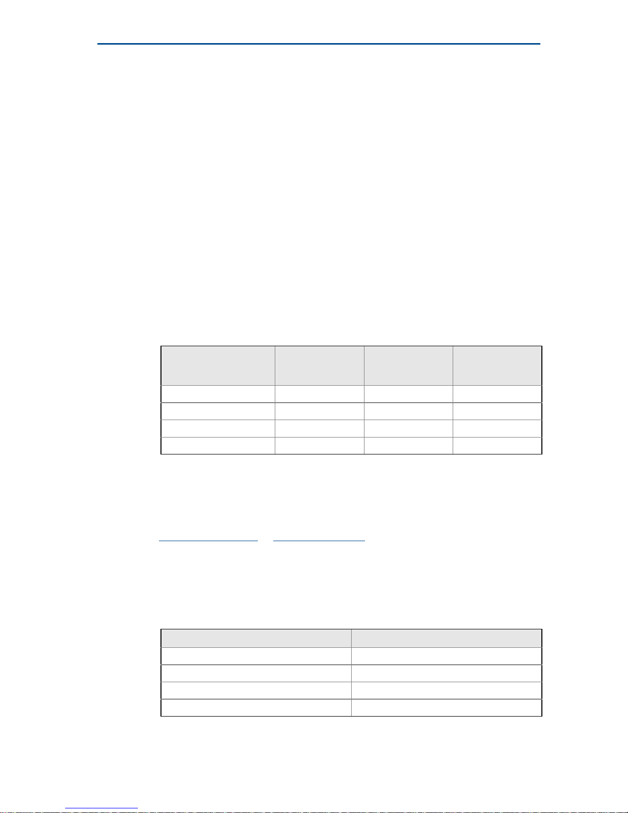
e. Year of manufacture: marked on the product label
12. Cable selection
a. It is the responsibility of the user to ensure that suitably temperature rated
cable is used. Note that the cable entry temperature may exceed 70 °C.
The table below is a guide to selection:
Temperature
classes
Maximum surface
temperature (T)
Maximum
ambient air
temperature (Ta)
Maximum process
temperature (Tp)
T6, T5, T4, T3, T2, T1 T85 °C 75 °C 75 °C
T5, T4, T3, T2, T1 T100 °C 70 °C 90 °C
T4, T3, T2, T1 T135 °C 65 °C 125 °C
T3, T2, T1 T160 °C 50 °C 150 °C
T class Cable temperature rating
T6 Above 85 °C
T5 Above 100 °C
T4 Above 135 °C
T3 Above 160 °C
Page 24

December 2016
24
Quick Start Guide
13. Special conditions of use
a. The user is to ensure the probe assembly is installed in such a way to
prevent any damage due to impact or ignition source due to friction.
b. Under certain extreme circumstances, a non-standard paint on the
enclosure of the Rosemount 2120 may generate an ignition-capable level of
electrostatic charge. Therefore, the Rosemount 2120 shall not be installed
in a location where the external conditions are conducive to the build-up of
electrostatic charge on such surfaces. Additionally, the Rosemount 2120
shall only be cleaned with a damp cloth.
c. The user is to ensure the ambient air temperature (Ta) and the process
temperature (Tp) are within the range detailed above for the T class of the
specific flammable gases or vapors present.
d. The user is to ensure the ambient air temperature (Ta) and the process
temperature (Tp) are within the range detailed above for the maximum
surface temperature of the specific flammable dusts present.
10.14 Instructions for hazardous area installations (I1 and I7)
Model numbers covered:
2120***H*I1**, 2120***K*I1**
2120***H*I7**, 2120***K*I7*
(“*” indicates options in construction, function and materials)
The following instructions apply to the equipment covered by certificates
numbered
Sira 05ATEX2130X and IECEx Sir 06.0070X:
1. The Intrinsically Safe approved versions of the 2120 may be used in a
hazardous area with explosive gases and vapors with apparatus groups IIC, IIB,
and IIA, and with temperature classes T1, T2, T3, T4, and T5 [IECEx: in Zones 0,
1, and 2].
The temperature class of the installation will be determined from the higher of
the process or ambient temperature.
2. The equipment may be used in a hazardous area with explosive dusts with
apparatus groups IIIC, IIIB, and IIIA [
IECEx: in Zones 20, 21, and 22].
The maximum surface temperature of the installation will be determined from
the higher of the process or ambient temperature.
3. It is a special condition of the certification that the temperature of the
electronics housing is in the range of –50 to +80 °C.
It must not be used outside this range. It will be necessary to limit the external
ambient temperature if the process temperature is high.
See also “Technical data” below.
4. Suitably trained personnel shall carry out installation in accordance with the
applicable code of practice.
5. The user should not repair this equipment.
6. If the equipment is likely to come into contact with
aggressive substances, it is
the responsibility of the user to take
suitable precautions that prevent it from
being adversely affected, thus ensuring that the type of protection is not
compromised.
Page 25
Quick Start Guide
25
December 2016
Aggressive substances – e.g. acidic liquids or gases that may attack metals or
solvents that may affect polymeric materials.
Suitable precautions – e.g. regular checks as part of routine inspections or
establishing from the material’s data sheet that it is resistant to specific
chemicals.
7. The Rosemount 2120 meets the requirements of clause 6.3.12 (Isolation of
circuits from earth or frame) in EN 60079-11 (IEC 60079-11).
8. Technical data:
a. Coding:
ATEX: II 1 G D, Ex ia IIC T5...T2 Ga, Ex ia IIIC T85 °C...T265 °C Da
IECEx: Ex ia IIC T5...T2 Ga, Ex ia IIIC T85 °C...T265 °C Da
b. Temperature:
2120***H*I1**, 2120***H*I7**:
Minimum ambient air temperature (Ta) = –40 °C
Minimum process temperature (Tp) = –40 °C
2120***K*I1**, 2120***K*I7**:
Minimum ambient air temperature (Ta) = –40 °C
Minimum process temperature (Tp) = –40 °C
c. Input parameters:
NAMUR electronics:
Ui =15 V, Ii = 32 mA, Pi = 0.1 W, Ci = 12 nF, Li = 0.06 mH
8/16 mA electronics:
Ui = 30 V, Ii = 93 mA, Pi = 0.65 W, Ci = 12 nF, Li = 0.035 mH
d. Materials:
See the Rosemount 2120 Product Data Sheet
or Reference Manual.
e. Year of manufacture: printed on product label
Gas (Ga) and Dust (Da)
Temperature
classes
Maximum surface
temperature (T)
Maximum ambient air
temperature (Ta)
Maximum process
temperature (Tp)
T5, T4, T3, T2, T1 T85 °C 80 °C 60 °C
T4, T3, T2, T1 T120 °C 60 °C 115 °C
T3, T2, T1 T155 °C 50 °C 150 °C
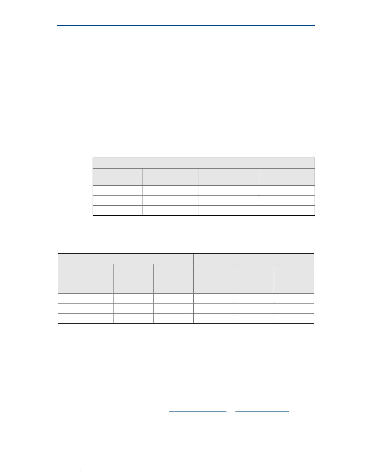
Gas (Ga) Dust (Da)
Temperature
classes
Maximum
ambient air
temperature
(Ta)
Maximum
process
temperature
(Tp)
Maximum
surface
temperature
(T)
Maximum
ambient air
temperature
(Ta)
Maximum
process
temperature
(Tp)
T5, T4, T3, T2, T1 80 °C 60 °C T85 70 °C 60 °C
T4, T3, T2, T1 60 °C 115 °C T120 60 °C 115 °C
T3, T2, T1 50 °C 150 °C T155 50 °C 150 °C
Page 26
December 2016
26
Quick Start Guide
9. Special conditions of use
a. If the enclosure is made of an alloy or plastic material, the following
precautions must be observed:
(i) The metallic alloy used for the enclosure material may be at the
accessible surface of this equipment; in the event of rare accidents, ignition
sources due to impact and friction sparks could occur. This shall be
considered when the Rosemount 2120 is being installed in locations that
specifically require Equipment Protection Level Ga or Da [ATEX: group II,
category 1G equipment] [
IECEx: in Zone 0 and 20 locations].
(ii) Under certain extreme circumstances, the non-metallic parts
incorporated in the enclosure of the Rosemount 2120 may generate an
ignition-capable level of electrostatic charge. Therefore, when they are
used for applications that specifically require Equipment Protection Level
Ga or Da [ATEX: group II, category 1G equipment] [IECEx: in Zone 0 and 20
locations], the Rosemount 2120 shall not be installed in a location where
the external conditions are conducive to the build-up of electrostatic
charge on such surfaces. Additionally, the Rosemount 2120 shall only be
cleaned with a damp cloth.
b. Ensure the ambient air temperature (Ta) and the process temperature (Tp)
are within the range detailed above for the T class of the specific explosive
gases or vapors present.
c. Ensure the ambient air temperature (Ta) and the process temperature (Tp)
are within the range detailed above for the maximum surface temperature
of the specific explosive dusts present.
10.15 Instructions for hygienic installations
The following instructions are for a Rosemount 2120 Level Switch (“level switch”)
with 38 mm or 51 mm Tri Clamp fitting covered by 3-A authorization 3496 and
EHEDG certificate 102016, and ASME-BPE and FDA compliance:
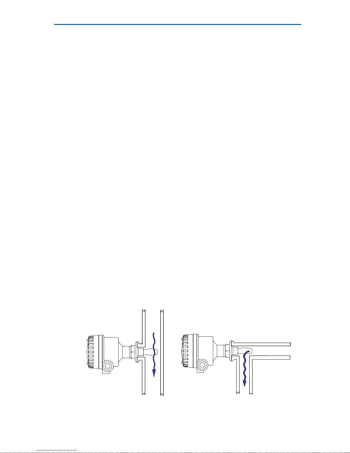
1. The level switch is suitable for installation on pipeline (with fork gap in line
with the flow) and on closed vessels (with the fork gap vertical).
EHEDG only recommend horizontal stub mounting in pipelines:
2. Installation of the level switch shall be carried out by suitably trained
personnel, in accordance with the applicable standards and code of practice.
O
K
OK
Page 27
Quick Start Guide
27
December 2016
3. Inspection and maintenance of the level switch shall be carried out by suitably
trained personnel, in accordance with the applicable standards and code of
practice.
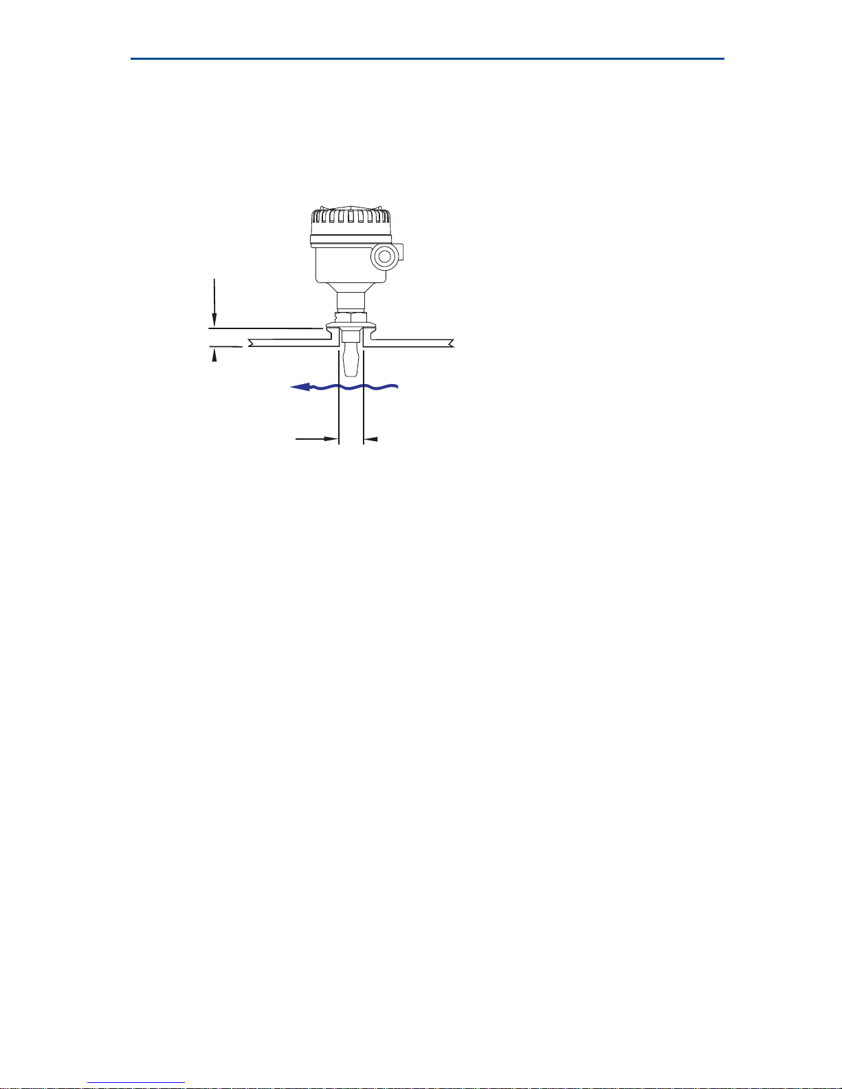
4. If the level switch is installed in a stub then, to ensure clean-ability, the length
(L) must not exceed the diameter (D) with a minimum diameter of 46 mm.
If the stub diameter is < 46 mm then L < 2 * (D - 23).
5. The certification of the level switch relies upon the following materials used in
its construction:
Product contact surfaces
Probe: Stainless steel 316/316L
d. Non-product contact surfaces:
Enclosure (Metal): Aluminum alloy ASTM B85 360.0 or ANSI AA360.0
Enclosure (plastic): Glass-filled (30%) nylon 66
Seals: Silicone, Nitrile rubber and polyethylene
Cable entry devices: Nylon (PA6)
6. It is the responsibility of the user to ensure:
a. The materials listed in instruction 5 are suitable for the media and cleaning
(sanitizing) processes.
b. The level switch installation is drainable and cleanable.
c. That the joint requirements between the probe and the vessel/pipe are
compatible with the process media, applicable standards and code of
practice.
In EHEDG applications, the seals (gaskets) used shall be defined as in the
EHEDG position paper “Easy cleanable pipe couplings and process
connections”.
d. That only suitable cable entry devices will be utilized when connecting the
level switch to maintain IP66.
e. That any unused cable entries are sealed with suitable stopping plugs to
maintain IP66.
7. The level switch is suitable for Cleaning-In-Place (CIP) up to 160 °F (71 °C).
8. The level switch is suitable for Steaming-In-Place (SIP) up to 275 °F (135 °C).
D
L
Page 28
December 2016
28
Quick Start Guide
Figure 9. EC Declaration of Conformity for Rosemount 2120 (Page 1)
Page 29

Quick Start Guide
29
December 2016
Figure 10. EC Declaration of Conformity for Rosemount 2120 (Page 2)
Page 30
December 2016
30
Quick Start Guide
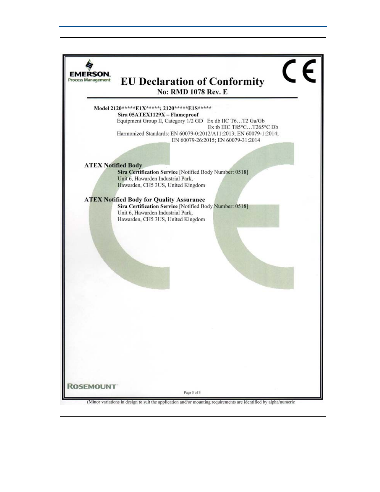
Figure 11. EC Declaration of Conformity for Rosemount 2120 (Page 3)
Page 31

Quick Start Guide
31
December 2016
ᴹ
China RoHS
㇑᧗⢙䍘䎵䗷ᴰབྷ⎃ᓖ䲀٬Ⲵ䜘Ԧරࡇ㺘
Rosemount 2120
List of
Rosemount 2120
Parts with China RoHS Concentration above MCVs
䜘Ԧ〠
Part Name
ᴹᇣ⢙䍘䍘
/ Hazardous Substances
䫵
Lead
(Pb)
⊎
Mercury
(Hg)
䭹
Cadmium
(Cd)
ޝԧ䬜䬜
Hexavalent
Chromium
(Cr +6)
ཊⓤ㚄㚄㤟
Polybrominated
biphenyls
(PBB)
ཊⓤ㚄㚄㤟䟊
Polybrominated
diphenyl ethers
(PBDE)
⭥ᆀ㓴Ԧ
Electronics
Assembly
XO O O O O
༣փ㓴Ԧ
Housing
Assembly
OO O X O O
Րᝏಘ㓴Ԧ
Sensor
Assembly
XO O O O O
ᵜ㺘Ṭ㌫ᦞ
SJ/T11364
Ⲵ㿴ᇊ㘼ࡦ
This table is proposed in accordance with the provision of SJ/T11364.
O:
Ѫ䈕䜘ԦⲴᡰᴹ൷䍘ᶀᯉѝ䈕ᴹᇣ⢙䍘Ⲵ䟿൷վҾ
GB/T 26572
ᡰ㿴ᇊⲴ䲀䟿㾱≲
O: Indicate that said hazardous substance in all of the homogeneous materials for this part is below the limit requirement of
GB/T 26572.
X:
Ѫ൘䈕䜘Ԧᡰ֯⭘Ⲵᡰᴹ൷䍘ᶀᯉ䟼ˈ㠣ቁᴹа㊫൷䍘ᶀᯉѝ䈕ᴹᇣ⢙䍘Ⲵ䟿儈Ҿ
GB/T 26572
ᡰ㿴ᇊⲴ䲀䟿㾱≲
X: Indicate that said hazardous substance contained in at least one of the homogeneous materials used for this part is above
the limit requirement of GB/T 26572.
Page 32

Global Headquarters
Emerson Automation Solutions
6021 Innovation Blvd.
Shakopee, MN 55379, USA
+1 800 999 9307 or +1 952 906 8888
+1 952 949 7001
[email protected]
North America Regional Office
Emerson Automation Solutions
8200 Market Blvd.
Chanhassen, MN 55317, USA
+1 800 999 9307 or +1 952 906 8888
+1 952 949 7001
[email protected]
Latin America Regional Office
Emerson Automation Solutions
1300 Concord Terrace, Suite 400
Sunrise, FL 33323, USA
+1 954 846 5030
+1 954 846 5121
[email protected]
Linkedin.com/company/Emerson-Automation-Solutions
Twitter.com/Rosemount_News
Facebook.com/Rosemount
Youtube.com/user/RosemountMeasurement
Google.com/+RosemountMeasurement
Standard Terms and Conditions of Sale can be found at
www.Emerson.com/en-us/Terms-of-Use
The Emerson logo is a trademark and service mark of Emerson
Electric Co.
Rosemount and Rosemount logotype are trademarks of Emerson .
ROCKWOOL is a registered trademark of ROCKWOOL International
A/S and/or its affiliates.
3-A is a trademark of 3-A Sanitary Standards, Inc.
All other marks are the property of their respective owners.
© 2016 Emerson. All rights reserved.
Europe Regional Office
Emerson Automation Solutions Europe GmbH
Neuhofstrasse 19a P.O. Box 1046
CH 6340 Baar
Switzerland
+41 (0) 41 768 6111
+41 (0) 41 768 6300
[email protected]
Asia Pacific Regional Office
Emerson Automation Solutions Asia Pacific Pte Ltd
1 Pandan Crescent
Singapore 128461
+65 6777 8211
+65 6777 0947
Middle East and Africa Regional Office
Emerson Automation Solutions
Emerson FZE P.O. Box 17033,
Jebel Ali Free Zone - South 2
Dubai, United Arab Emirates
+971 4 8118100
+971 4 8865465
Quick Start Guide
00825-0100-4030, Rev FA
December 2016
*00825-0100-4030*
 Loading...