

Page 1

Reference Manual
00809-0100-4102, Rev AA
May 2013
Rosemount 2051 Wireless Pressure Transmitters
Pressure, Level, and Flow Solutions with WirelessHART™
Protocol
Page 2

Page 3

Reference Manual
00809-0100-4102, Rev AA
Rosemount 2051 Wireless Pressure, Flow,
and Level Solutions
Read this manual before working with the product. For personal and system safety, and for
optimum product performance, make sure you thoroughly understand the contents before
installing, using, or maintaining this product.
For technical assistance, contacts are listed below:
Customer Central
Technical support, quoting, and order-related questions.
United States - 1-800-999-9307 (7:00 am to 7:00 pm CST)
Asia Pacific- 65 777 8211
Europe/ Middle East/ Africa - 49 (8153) 9390
North American Response Center
Equipment service needs.
1-800-654-7768 (24 hours—includes Canada)
Outside of these areas, contact your local Emerson Process Management representative.
The products described in this document are NOT designed for nuclear-qualified
applications. Using non-nuclear qualified products in applications that require
nuclear-qualified hardware or products may cause inaccurate readings.
For information on Emerson Process Management nuclear-qualified products, contact your
local Rosemount Sales Representative.
i
Page 4

Reference Manual
00809-0100-4102, Rev AA
Explosions could result in death or serious injury:
Installation of this transmitter in an explosive environment must be in accordance with the
appropriate local, national, and international standards, codes, and practices. Please review
the approvals section of the 2051 reference manual for any restrictions associated with a
safe installation.
Before connecting a HART-based communicator in an explosive atmosphere, make
sure the instruments in the loop are installed in accordance with intrinsically safe or
non-incendive field wiring practices.
This device complies with Part 15 of the FCC Rules. Operation is subject to the following
conditions.
This device may not cause harmful interference. This device must accept any interference
received, including interference that may cause undesired operation.
This device must be installed to ensure a minimum antenna separation distance of 8 in.
(20cm) from all persons.
Process leaks may cause harm or result in death.
To avoid process leaks, only use the o-ring designed to seal with the corresponding
flange adapter.
Electrical shock can result in death or serious injury.
Avoid contact with the leads and the terminals. High voltage that may be present on
leads can cause electrical shock.
The Rosemount 2051 and all other wireless devices should be installed only after the Smart
Wireless Gateway has been installed and is functioning properly. Wireless devices should
also be powered up in order of proximity from the Smart Wireless Gateway, beginning with
the closest. This will result in a simpler and faster network installation.
ii
Page 5
Reference Manual
00809-0100-4102, Rev AA
Shipping considerations for wireless products (Lithium Batteries: Green Power Module,
model number 701PGNKF):
The unit was shipped to you without the Power Module installed. Please remove the
Power Module from the unit prior to shipping.
Each power module contains one “D” size primary lithium-thionyl chloride battery.
Primary lithium batteries are regulated in transportation by the U.S. Department of
Transportation, and are also covered by IATA (International Air Transport Association),
ICAO (International Civil Aviation Organization), and ARD (European Ground
Transportation of Dangerous Goods). It is the responsibility of the shipper to ensure
compliance with these or any other local requirements. Please consult current
regulations and requirements before shipping.
The power module with the wireless unit contains one “D” size primary lithium-thionyl
chloride battery (Green Power Module, model number 701PGNKF). Each battery contains
approximately 5.0 grams of lithium. Under normal conditions, the battery materials are
self-contained and are not reactive as long as the battery and the pack integrity are
maintained. Care should be taken to prevent thermal, electrical or mechanical damage.
Contacts should be protected to prevent premature discharge.
Battery hazards remain when cells are discharged.
Power modules should be stored in a clean and dry area. For maximum battery life, storage
temperature should not exceed 30 °C (86 °F).
The Power Module may be replaced in a hazardous area. The Power Module has surface
resistivity greater than one gigaohm and must be properly installed in the wireless device
enclosure. Care must be taken during transportation to and from the point of installation to
prevent electrostatic charge build-up.
Using the Rosemount 2051 Wireless Pressure Transmitter in a manner other than what is
specified by the manufacturer may impair the protection provided by the equipment.
iii
Page 6

Reference Manual
00809-0100-4102, Rev AA
iv
Page 7

Reference Manual
00809-0100-4102, Rev AA
Contents
1Section 1: Introduction
Table of Contents
May 2013
1.1 Using this manual. . . . . . . . . . . . . . . . . . . . . . . . . . . . . . . . . . . . . . . . . . . . . . . . . . . . . . . 1
1.2 Models covered . . . . . . . . . . . . . . . . . . . . . . . . . . . . . . . . . . . . . . . . . . . . . . . . . . . . . . . . 1
1.2.1 Rosemount 2051C Coplanar
1.2.2 Rosemount 2051T in-line Pressure Transmitter . . . . . . . . . . . . . . . . . . . . . . .1
1.2.3 Rosemount 2051L Level Transmitter . . . . . . . . . . . . . . . . . . . . . . . . . . . . . . . .2
1.2.4 Rosemount 2051CF Flowmeters . . . . . . . . . . . . . . . . . . . . . . . . . . . . . . . . . . . .2
1.3 WirelessHART installation flowchart . . . . . . . . . . . . . . . . . . . . . . . . . . . . . . . . . . . . . . 3
1.4 Transmitter overview . . . . . . . . . . . . . . . . . . . . . . . . . . . . . . . . . . . . . . . . . . . . . . . . . . . 4
1.5 Considerations before transmitter installation. . . . . . . . . . . . . . . . . . . . . . . . . . . . . .5
1.5.1 Wireless considerations . . . . . . . . . . . . . . . . . . . . . . . . . . . . . . . . . . . . . . . . . . . . 5
1.5.2 Mechanical . . . . . . . . . . . . . . . . . . . . . . . . . . . . . . . . . . . . . . . . . . . . . . . . . . . . . . .6
1.5.3 Electrical . . . . . . . . . . . . . . . . . . . . . . . . . . . . . . . . . . . . . . . . . . . . . . . . . . . . . . . . .6
™
Pressure Transmitter . . . . . . . . . . . . . . . . . . . 1
1.5.4 Environmental . . . . . . . . . . . . . . . . . . . . . . . . . . . . . . . . . . . . . . . . . . . . . . . . . . . .7
1.6 Service support. . . . . . . . . . . . . . . . . . . . . . . . . . . . . . . . . . . . . . . . . . . . . . . . . . . . . . . . .7
1.7 Product Recycling/Disposal . . . . . . . . . . . . . . . . . . . . . . . . . . . . . . . . . . . . . . . . . . . . . .8
2Section 2: Configuration
2.1 Overview . . . . . . . . . . . . . . . . . . . . . . . . . . . . . . . . . . . . . . . . . . . . . . . . . . . . . . . . . . . . . . 9
2.2 Safety messages. . . . . . . . . . . . . . . . . . . . . . . . . . . . . . . . . . . . . . . . . . . . . . . . . . . . . . . . 9
2.3 Required bench top configuration . . . . . . . . . . . . . . . . . . . . . . . . . . . . . . . . . . . . . . .10
2.3.1 Connection diagrams. . . . . . . . . . . . . . . . . . . . . . . . . . . . . . . . . . . . . . . . . . . . .11
2.4 Basic setup. . . . . . . . . . . . . . . . . . . . . . . . . . . . . . . . . . . . . . . . . . . . . . . . . . . . . . . . . . . .11
2.4.1 Set device tag . . . . . . . . . . . . . . . . . . . . . . . . . . . . . . . . . . . . . . . . . . . . . . . . . . .11
2.4.2 Join device to network . . . . . . . . . . . . . . . . . . . . . . . . . . . . . . . . . . . . . . . . . . . .12
2.4.3 Configure update rate . . . . . . . . . . . . . . . . . . . . . . . . . . . . . . . . . . . . . . . . . . . .12
2.4.4 Set process variable units . . . . . . . . . . . . . . . . . . . . . . . . . . . . . . . . . . . . . . . . .13
2.4.5 Remove Power Module . . . . . . . . . . . . . . . . . . . . . . . . . . . . . . . . . . . . . . . . . . .13
2.5 Configure for Pressure. . . . . . . . . . . . . . . . . . . . . . . . . . . . . . . . . . . . . . . . . . . . . . . . . .13
2.5.1 Re-Mapping device variables . . . . . . . . . . . . . . . . . . . . . . . . . . . . . . . . . . . . . .13
2.5.2 Set range points . . . . . . . . . . . . . . . . . . . . . . . . . . . . . . . . . . . . . . . . . . . . . . . . .14
2.5.3 Set transmitter percent of range (transfer function) . . . . . . . . . . . . . . . . . .15
2.6 Configure for Level and Flow . . . . . . . . . . . . . . . . . . . . . . . . . . . . . . . . . . . . . . . . . . . .16
Tab le of Cont ents
2.6.1 Configuring scaled variable. . . . . . . . . . . . . . . . . . . . . . . . . . . . . . . . . . . . . . . .16
i
Page 8

Table of Contents
May 2013
Reference Manual
00809-0100-4102, Rev AA
2.6.2 Re-Mapping device variables . . . . . . . . . . . . . . . . . . . . . . . . . . . . . . . . . . . . . .18
2.6.3 Set range points . . . . . . . . . . . . . . . . . . . . . . . . . . . . . . . . . . . . . . . . . . . . . . . . .19
2.7 Review configuration data . . . . . . . . . . . . . . . . . . . . . . . . . . . . . . . . . . . . . . . . . . . . . .20
2.7.1 Review pressure information . . . . . . . . . . . . . . . . . . . . . . . . . . . . . . . . . . . . . .20
2.7.2 Review device information . . . . . . . . . . . . . . . . . . . . . . . . . . . . . . . . . . . . . . . .20
2.7.3 Review radio information . . . . . . . . . . . . . . . . . . . . . . . . . . . . . . . . . . . . . . . . .21
2.7.4 Review operating parameters . . . . . . . . . . . . . . . . . . . . . . . . . . . . . . . . . . . . .21
2.8 Configuring the LCD display. . . . . . . . . . . . . . . . . . . . . . . . . . . . . . . . . . . . . . . . . . . . .22
2.9 Detailed transmitter setup . . . . . . . . . . . . . . . . . . . . . . . . . . . . . . . . . . . . . . . . . . . . . .23
2.9.1 Configure process alerts . . . . . . . . . . . . . . . . . . . . . . . . . . . . . . . . . . . . . . . . . .23
2.9.2 Damping. . . . . . . . . . . . . . . . . . . . . . . . . . . . . . . . . . . . . . . . . . . . . . . . . . . . . . . .23
2.9.3 Write protect . . . . . . . . . . . . . . . . . . . . . . . . . . . . . . . . . . . . . . . . . . . . . . . . . . . .24
2.10Diagnostics and service . . . . . . . . . . . . . . . . . . . . . . . . . . . . . . . . . . . . . . . . . . . . . . . .24
2.10.1Device reset. . . . . . . . . . . . . . . . . . . . . . . . . . . . . . . . . . . . . . . . . . . . . . . . . . . . .25
2.10.2Join status. . . . . . . . . . . . . . . . . . . . . . . . . . . . . . . . . . . . . . . . . . . . . . . . . . . . . . .25
2.10.3Number of available neighbors . . . . . . . . . . . . . . . . . . . . . . . . . . . . . . . . . . . .26
2.11Advanced Functions for HART Protocol. . . . . . . . . . . . . . . . . . . . . . . . . . . . . . . . . . .27
2.11.1Saving, Recalling, and Cloning Configuration Data . . . . . . . . . . . . . . . . . . .27
3Section 3: Installation
3.1 Overview . . . . . . . . . . . . . . . . . . . . . . . . . . . . . . . . . . . . . . . . . . . . . . . . . . . . . . . . . . . . .29
3.2 Safety messages. . . . . . . . . . . . . . . . . . . . . . . . . . . . . . . . . . . . . . . . . . . . . . . . . . . . . . .29
3.2.1 Warnings (). . . . . . . . . . . . . . . . . . . . . . . . . . . . . . . . . . . . . . . . . . . . . . . . . . . . . .30
3.3 Considerations . . . . . . . . . . . . . . . . . . . . . . . . . . . . . . . . . . . . . . . . . . . . . . . . . . . . . . . .31
3.3.1 Installation considerations . . . . . . . . . . . . . . . . . . . . . . . . . . . . . . . . . . . . . . . .31
3.3.2 Wireless considerations . . . . . . . . . . . . . . . . . . . . . . . . . . . . . . . . . . . . . . . . . . .31
3.3.3 Mechanical considerations . . . . . . . . . . . . . . . . . . . . . . . . . . . . . . . . . . . . . . . .32
3.3.4 Environmental considerations . . . . . . . . . . . . . . . . . . . . . . . . . . . . . . . . . . . . .32
3.3.5 Draft range considerations . . . . . . . . . . . . . . . . . . . . . . . . . . . . . . . . . . . . . . . .33
3.4 Installation procedures . . . . . . . . . . . . . . . . . . . . . . . . . . . . . . . . . . . . . . . . . . . . . . . . .35
3.4.1 Mount the transmitter . . . . . . . . . . . . . . . . . . . . . . . . . . . . . . . . . . . . . . . . . . . .36
3.4.2 Impulse piping. . . . . . . . . . . . . . . . . . . . . . . . . . . . . . . . . . . . . . . . . . . . . . . . . . .41
3.4.3 Process connections. . . . . . . . . . . . . . . . . . . . . . . . . . . . . . . . . . . . . . . . . . . . . .43
3.4.4 Inline process connection . . . . . . . . . . . . . . . . . . . . . . . . . . . . . . . . . . . . . . . . .44
3.4.5 Power Module installation. . . . . . . . . . . . . . . . . . . . . . . . . . . . . . . . . . . . . . . . .45
3.4.6 Installing the LCD display . . . . . . . . . . . . . . . . . . . . . . . . . . . . . . . . . . . . . . . . .46
3.5 Rosemount 304, 305 and 306 integral manifolds . . . . . . . . . . . . . . . . . . . . . . . . . .47
ii
Table of Contents
Page 9

Reference Manual
00809-0100-4102, Rev AA
4Section 4: Commissioning
Table of Contents
May 2013
3.5.1 Rosemount 305 Integral Manifold installation procedure . . . . . . . . . . . . .48
3.5.2 Rosemount 306 Integral Manifold installation procedure . . . . . . . . . . . . .49
3.5.3 Rosemount 304 Conventional Manifold installation procedure . . . . . . . .50
3.5.4 Manifold operation . . . . . . . . . . . . . . . . . . . . . . . . . . . . . . . . . . . . . . . . . . . . . . .50
4.1 Overview . . . . . . . . . . . . . . . . . . . . . . . . . . . . . . . . . . . . . . . . . . . . . . . . . . . . . . . . . . . . .55
4.2 Safety messages. . . . . . . . . . . . . . . . . . . . . . . . . . . . . . . . . . . . . . . . . . . . . . . . . . . . . . .55
4.2.1 Warnings (). . . . . . . . . . . . . . . . . . . . . . . . . . . . . . . . . . . . . . . . . . . . . . . . . . . . . .56
4.3 Viewing network status . . . . . . . . . . . . . . . . . . . . . . . . . . . . . . . . . . . . . . . . . . . . . . . .57
4.4 Verifying operation . . . . . . . . . . . . . . . . . . . . . . . . . . . . . . . . . . . . . . . . . . . . . . . . . . . .57
4.4.1 Using the Field Communicator. . . . . . . . . . . . . . . . . . . . . . . . . . . . . . . . . . . . .60
4.5 Configuring transmitter security. . . . . . . . . . . . . . . . . . . . . . . . . . . . . . . . . . . . . . . . .61
5Section 5: Operation and maintenance
5.1 Overview . . . . . . . . . . . . . . . . . . . . . . . . . . . . . . . . . . . . . . . . . . . . . . . . . . . . . . . . . . . . .63
5.2 Safety messages. . . . . . . . . . . . . . . . . . . . . . . . . . . . . . . . . . . . . . . . . . . . . . . . . . . . . . .63
5.3 Calibration overview . . . . . . . . . . . . . . . . . . . . . . . . . . . . . . . . . . . . . . . . . . . . . . . . . . .63
5.3.1 Determining necessary Sensor Trims . . . . . . . . . . . . . . . . . . . . . . . . . . . . . . .64
5.3.2 Determining calibration frequency . . . . . . . . . . . . . . . . . . . . . . . . . . . . . . . . .65
5.3.3 Compensating for Span line pressure effects (range 4 and range 5). . . . .66
5.4 Trim the pressure signal . . . . . . . . . . . . . . . . . . . . . . . . . . . . . . . . . . . . . . . . . . . . . . . .67
5.4.1 Sensor Trim Overview . . . . . . . . . . . . . . . . . . . . . . . . . . . . . . . . . . . . . . . . . . . .67
5.4.2 Sensor Trim . . . . . . . . . . . . . . . . . . . . . . . . . . . . . . . . . . . . . . . . . . . . . . . . . . . . .68
5.4.3 Recall Factory Trim—Sensor Trim. . . . . . . . . . . . . . . . . . . . . . . . . . . . . . . . . . .70
5.4.4 Line Pressure Effect (Range 2 and Range 3) . . . . . . . . . . . . . . . . . . . . . . . . . .70
5.4.5 Compensating for Line Pressure (Range 4 and Range 5) . . . . . . . . . . . . . . .70
5.5 LCD Screen Messages . . . . . . . . . . . . . . . . . . . . . . . . . . . . . . . . . . . . . . . . . . . . . . . . . .73
5.5.1 Startup Screen Sequence . . . . . . . . . . . . . . . . . . . . . . . . . . . . . . . . . . . . . . . . .73
5.5.2 Diagnostic Button Screen Sequence . . . . . . . . . . . . . . . . . . . . . . . . . . . . . . . .75
5.5.3 Network Diagnostic Status Screens. . . . . . . . . . . . . . . . . . . . . . . . . . . . . . . . .76
Tab le of Cont ents
5.5.4 Device Diagnostic Screens . . . . . . . . . . . . . . . . . . . . . . . . . . . . . . . . . . . . . . . .79
6Section 6: Troubleshooting
6.1 Overview . . . . . . . . . . . . . . . . . . . . . . . . . . . . . . . . . . . . . . . . . . . . . . . . . . . . . . . . . . . . .83
6.2 Safety messages. . . . . . . . . . . . . . . . . . . . . . . . . . . . . . . . . . . . . . . . . . . . . . . . . . . . . . .83
6.2.1 Warnings (). . . . . . . . . . . . . . . . . . . . . . . . . . . . . . . . . . . . . . . . . . . . . . . . . . . . . .84
6.3 Removing from service . . . . . . . . . . . . . . . . . . . . . . . . . . . . . . . . . . . . . . . . . . . . . . . . .88
iii
Page 10

Table of Contents
May 2013
AAppendix A: Specifications and
Reference Data
Reference Manual
00809-0100-4102, Rev AA
A.1 Performance Specifications . . . . . . . . . . . . . . . . . . . . . . . . . . . . . . . . . . . . . . . . . . . . .89
A.1.1 Conformance to specification (±3s (Sigma)) . . . . . . . . . . . . . . . . . . . . . . . . .89
A.1.2 Digital output . . . . . . . . . . . . . . . . . . . . . . . . . . . . . . . . . . . . . . . . . . . . . . . . . . .89
A.2 Functional Specifications . . . . . . . . . . . . . . . . . . . . . . . . . . . . . . . . . . . . . . . . . . . . . . .92
A.2.1 Service. . . . . . . . . . . . . . . . . . . . . . . . . . . . . . . . . . . . . . . . . . . . . . . . . . . . . . . . . .92
A.2.2 Range and Sensor Limits . . . . . . . . . . . . . . . . . . . . . . . . . . . . . . . . . . . . . . . . . .93
A.3 Wireless Self-Organizing Networks. . . . . . . . . . . . . . . . . . . . . . . . . . . . . . . . . . . . . . .93
A.3.1 Overpressure limits . . . . . . . . . . . . . . . . . . . . . . . . . . . . . . . . . . . . . . . . . . . . . .94
A.3.2 Static pressure limit . . . . . . . . . . . . . . . . . . . . . . . . . . . . . . . . . . . . . . . . . . . . . .95
A.3.3 Burst pressure limits . . . . . . . . . . . . . . . . . . . . . . . . . . . . . . . . . . . . . . . . . . . . . .95
A.3.4 Temperature limits. . . . . . . . . . . . . . . . . . . . . . . . . . . . . . . . . . . . . . . . . . . . . . .95
A.3.5 Humidity Limits. . . . . . . . . . . . . . . . . . . . . . . . . . . . . . . . . . . . . . . . . . . . . . . . . .96
A.3.6 Volumetric Displacement . . . . . . . . . . . . . . . . . . . . . . . . . . . . . . . . . . . . . . . . .96
A.3.7 Damping. . . . . . . . . . . . . . . . . . . . . . . . . . . . . . . . . . . . . . . . . . . . . . . . . . . . . . . .96
A.4 Physical specifications. . . . . . . . . . . . . . . . . . . . . . . . . . . . . . . . . . . . . . . . . . . . . . . . . .97
A.4.1 Electrical connections . . . . . . . . . . . . . . . . . . . . . . . . . . . . . . . . . . . . . . . . . . . .97
A.4.2 Process connections. . . . . . . . . . . . . . . . . . . . . . . . . . . . . . . . . . . . . . . . . . . . . .97
A.4.3 Process-Wetted parts. . . . . . . . . . . . . . . . . . . . . . . . . . . . . . . . . . . . . . . . . . . . .97
A.4.4 Rosemount 2051L Process Wetted Parts . . . . . . . . . . . . . . . . . . . . . . . . . . . .98
A.4.5 Non-Wetted Parts . . . . . . . . . . . . . . . . . . . . . . . . . . . . . . . . . . . . . . . . . . . . . . . .98
A.4.6 Shipping Weights for 2051 Wireless Pressure Transmitter. . . . . . . . . . . 100
A.5 Dimensional Drawings . . . . . . . . . . . . . . . . . . . . . . . . . . . . . . . . . . . . . . . . . . . . . . . 101
A.6 Ordering Information . . . . . . . . . . . . . . . . . . . . . . . . . . . . . . . . . . . . . . . . . . . . . . . . 103
A.7 Options . . . . . . . . . . . . . . . . . . . . . . . . . . . . . . . . . . . . . . . . . . . . . . . . . . . . . . . . . . . . 127
A.8 Spare parts. . . . . . . . . . . . . . . . . . . . . . . . . . . . . . . . . . . . . . . . . . . . . . . . . . . . . . . . . . 130
BAppendix B: Product Certifications
B.1 Wireless Certifications. . . . . . . . . . . . . . . . . . . . . . . . . . . . . . . . . . . . . . . . . . . . . . . . 131
B.1.1 Approved manufacturing locations. . . . . . . . . . . . . . . . . . . . . . . . . . . . . . . 131
B.1.2 European directive information . . . . . . . . . . . . . . . . . . . . . . . . . . . . . . . . . . 131
B.1.3 Telecommunication compliance . . . . . . . . . . . . . . . . . . . . . . . . . . . . . . . . . 131
B.1.4 FCC and IC . . . . . . . . . . . . . . . . . . . . . . . . . . . . . . . . . . . . . . . . . . . . . . . . . . . . 131
B.1.5 Ordinary location certification for FM . . . . . . . . . . . . . . . . . . . . . . . . . . . . . 132
B.1.6 North American certifications . . . . . . . . . . . . . . . . . . . . . . . . . . . . . . . . . . . 132
B.1.7 CSA - Canadian Standards Association . . . . . . . . . . . . . . . . . . . . . . . . . . . . 132
B.1.8 European certifications . . . . . . . . . . . . . . . . . . . . . . . . . . . . . . . . . . . . . . . . . 132
iv
Table of Contents
Page 11

Reference Manual
00809-0100-4102, Rev AA
CAppendix C: Field Communicator Menu Trees and Fast Keys
DAppendix D: Network design best practices
Table of Contents
May 2013
C.1 Field Communicator menu trees. . . . . . . . . . . . . . . . . . . . . . . . . . . . . . . . . . . . . . . 135
D.1 Effective range . . . . . . . . . . . . . . . . . . . . . . . . . . . . . . . . . . . . . . . . . . . . . . . . . . . . . . 139
Tab le of Cont ents
v
Page 12

Table of Contents
May 2013
Reference Manual
00809-0100-4102, Rev AA
vi
Table of Contents
Page 13

Reference Manual
00809-0100-4102, Rev AA
Section 1 Introduction
Using this manual . . . . . . . . . . . . . . . . . . . . . . . . . . . . . . . . . . . . . . . . . . . . . . . . . . . . . . . .page 1
Models covered . . . . . . . . . . . . . . . . . . . . . . . . . . . . . . . . . . . . . . . . . . . . . . . . . . . . . . . . . . page 1
Service support . . . . . . . . . . . . . . . . . . . . . . . . . . . . . . . . . . . . . . . . . . . . . . . . . . . . . . . . . . page 7
Product Recycling/Disposal . . . . . . . . . . . . . . . . . . . . . . . . . . . . . . . . . . . . . . . . . . . . . . . page 8
1.1 Using this manual
The sections in this manual provide information on installing, operating, and maintaining the
Rosemount 2051 Wireless pressure transmitter with WirelessHART
organized as follows:
Section 2: Configuration provides instruction on commissioning and operating 2051
Wireless transmitters. Information on software functions, configuration parameters,
and online variables is also included.
Section 3: Installation contains mechanical and electrical installation instructions.
Section 4: Commissioning contains techniques for properly commissioning the device.
Section 1: Introduction
May 2013
™
protocol. The sections are
Section 5: Operation and maintenance contains operation and maintenance
techniques.
Section 6: Troubleshooting provides troubleshooting techniques for the most common
operating problems.
Appendix A: Specifications and Reference Data supplies reference and specification
data, as well as ordering information.
Appendix B: Product Certifications contains approval information.
Appendix C: Field Communicator Menu Trees and Fast Keys provides full menu trees
and abbreviated fast key sequences for commissioning tasks.
Appendix D: Network design best practices provides information on how to optimize
network reliability and performance.
1.2 Models covered
The following Rosemount 2051 Pressure Transmitters are covered by this manual:
1.2.1 Rosemount 2051C Coplanar™ Pressure Transmitter
Measures differential and gage pressure up to 2000 psi (137,9 bar).
Measures absolute pressure up to 4000 psi (275,8 bar)
1.2.2 Rosemount 2051T in-line Pressure Transmitter
Measures gage/absolute pressure up to 10000 psi (689,5 bar).
Introduction
1
Page 14

Section 1: Introduction
May 2013
1.2.3 Rosemount 2051L Level Transmitter
Measures level and specific gravity up to 300 psi (20,7 bar)
1.2.4 Rosemount 2051CF Flowmeters
Measures flow in line sizes from
1
/2 in. (15 mm) to 96 in. (2400 mm)
Reference Manual
00809-0100-4102, Rev AA
2
Introduction
Page 15
Reference Manual
Yes
START HERE
Bench
Configuration
and Calibration
Field Install
No
Set Pressure to
PV
(
page 13)
Set Range
Points
(page 14)
Select Transfer
Function for
Percent of Range
(
page 15)
Ver ify
Apply Pressure
Yes
Within
Specifications?
No
Refer to
Section 5:
Operation and
maintenance
Mount
Tra ns mit te r
(
page 36)
Install Power
Module
(
page 13)
Trim th e
Tra ns mit te r
(page 67)
Done
Review
Tra ns mi tt er
Configuration
(
page 20)
Confirm
Tra ns mit te r
Configuration
(
page 20)
Configure for
Pressure
Configure
Scaled Variable
(
page 16)
Set Scaled
Variab le to PV
(page 13)
Configure for
Level
Configure for
Flow
Configure
Scaled Variable
(
page 16)
Set Scaled
Variab le to PV
(page 13)
Check Process
Connection
(
page 43)
Join Device to
Network by
Setting Network
ID and Join Key
(
page 12)
Configure
Update Rate
(page 12)
Set Device Tag
(
page 11)
Set Process
Variable Units
(page 13)
Set Range Points
(page 14)
Set Range Points
(page 14)
00809-0100-4102, Rev AA
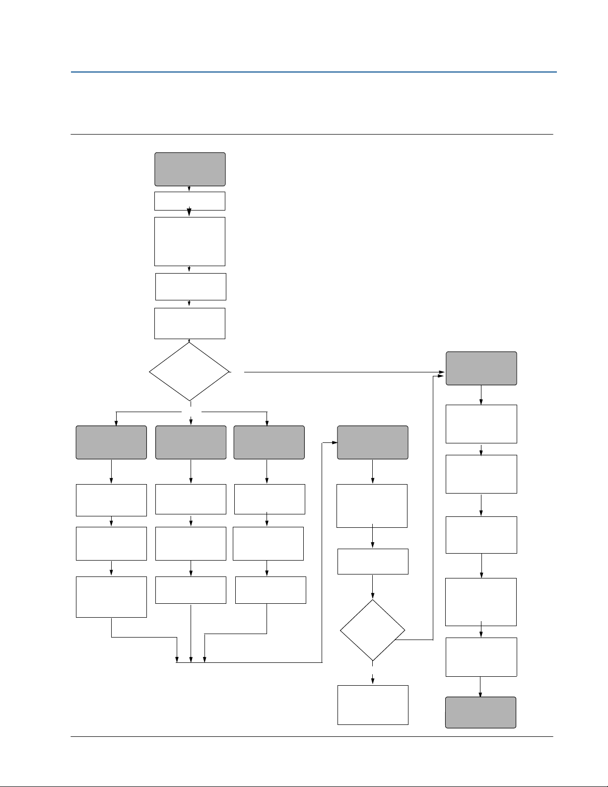
1.3 WirelessHART installation flowchart
Figure 1-1. WirelessHART installation flowchart
Section 1: Introduction
May 2013
Introduction
3
Page 16
Section 1: Introduction
May 2013
1.4 Transmitter overview
The Rosemount 2051C Coplanar design is offered for Differential Pressure (DP), Gage Pressure
(GP) and Absolute Pressure (AP) measurements. The Rosemount 2051C utilizes capacitance
sensor technology for DP and GP measurements. The Rosemount 2051T and 2051CA utilize
piezo-resistive sensor technology for AP and GP measurements.
The major components of the Rosemount 2051 Wireless transmitter are the sensor module and
the electronics housing. The sensor module contains the oil filled sensor system (isolating
diaphragms, oil fill system, and sensor) and the sensor electronics. The sensor electronics are
installed within the sensor module and include a temperature sensor, a memory module, and
the analog to digital signal converter (A/D converter). The electrical signals from the sensor
module are transmitted to the output electronics in the electronics housing. The electronics
housing contains the output electronics board, the antenna, and the battery. The basic block
diagram of the Rosemount 2051CD Wireless device is illustrated in Figure 1-3 on page 5.
For the Rosemount 2051, pressure is applied to the isolating diaphragm(s). The oil deflects the
sensor which then changes its capacitance or voltage signal. This signal is then changed to a
digital signal by the Signal Processing Module. The microprocessor then takes the signals from
the Signal Processing Module and calculates the correct output of the transmitter. This signal is
then sent via wireless communication to the Gateway.
Reference Manual
00809-0100-4102, Rev AA
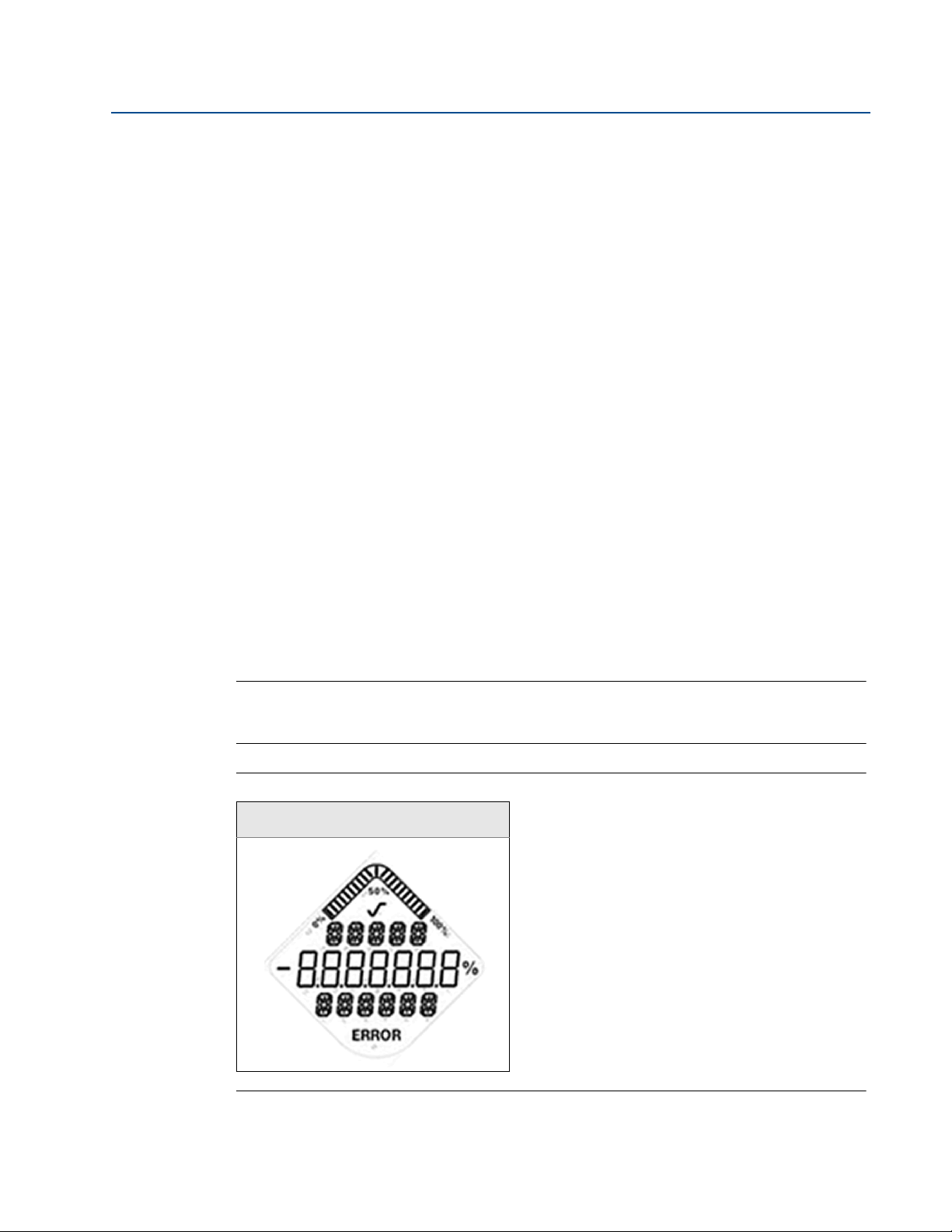
An optional LCD can be ordered that connects directly to the output electronics board which
maintains direct access to the signal terminals. The display indicates output and abbreviated
diagnostic messages. A clear display cover is provided. For WirelessHART output, the LCD
Display features a three-line display. The first line describes the process variable measured, the
second line displays the measured value, and the third line displays engineering units. The LCD
can also display diagnostics messages.
Note
LCD Display utilizes a 3-line, 7-digit character display and can display output and diagnostic
messages. See Figure 1-2.
Figure 1-2. LCD Display
LCD Display
4
Introduction
Page 17
Reference Manual
ABC
D
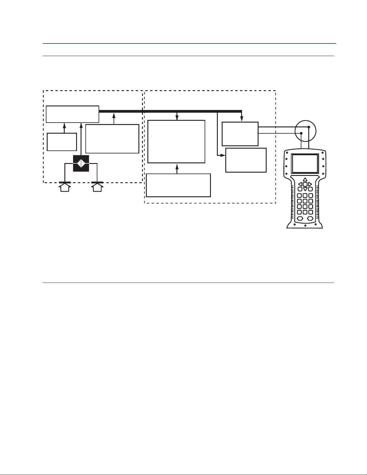
Signal Processing
Tem p.
Sensor
Sensor Module
Memory
Microprocessor
Sensor linearization
Rerange
Diagnostics
Engineering units
Communication
Memory
Configuration
Local HART
Handheld
Communicator
WirelessHART
Communication
00809-0100-4102, Rev AA
Figure 1-3. Block diagram of operation
Section 1: Introduction
May 2013
A. Sensor Module
B. Electronics Board
C. WirelessHART Signal to Control System
D. Field Communicator
1.5 Considerations before transmitter installation
1.5.1 Wireless considerations
Power up sequence
The Power Module should not be installed on any wireless device until the Smart Wireless
Gateway is installed and functioning properly. This transmitter uses the Green Power Module
(order model number 701PGNKF). Wireless devices should also be powered up in order of
proximity from the Smart Wireless Gateway, beginning with the closest. This will result in a
simpler and faster network installation. Enable Active Advertising on the Gateway to ensure that
new devices join the network faster. For more information, see the Smart Wireless Gateway
Manual (Doc. No. 00809-0200-4420).
Antenna position
The internal antenna is designed for multiple mounting orientations. The transmitter should be
mounted according to best practices for your pressure measurement application.
Introduction
5
Page 18
Section 1: Introduction
May 2013
Network design best practices
When mounting the device, recommended practices should be considered to achieve the best
wireless performance. See Appendix D: Network design best practices for more information on
recommended practices.
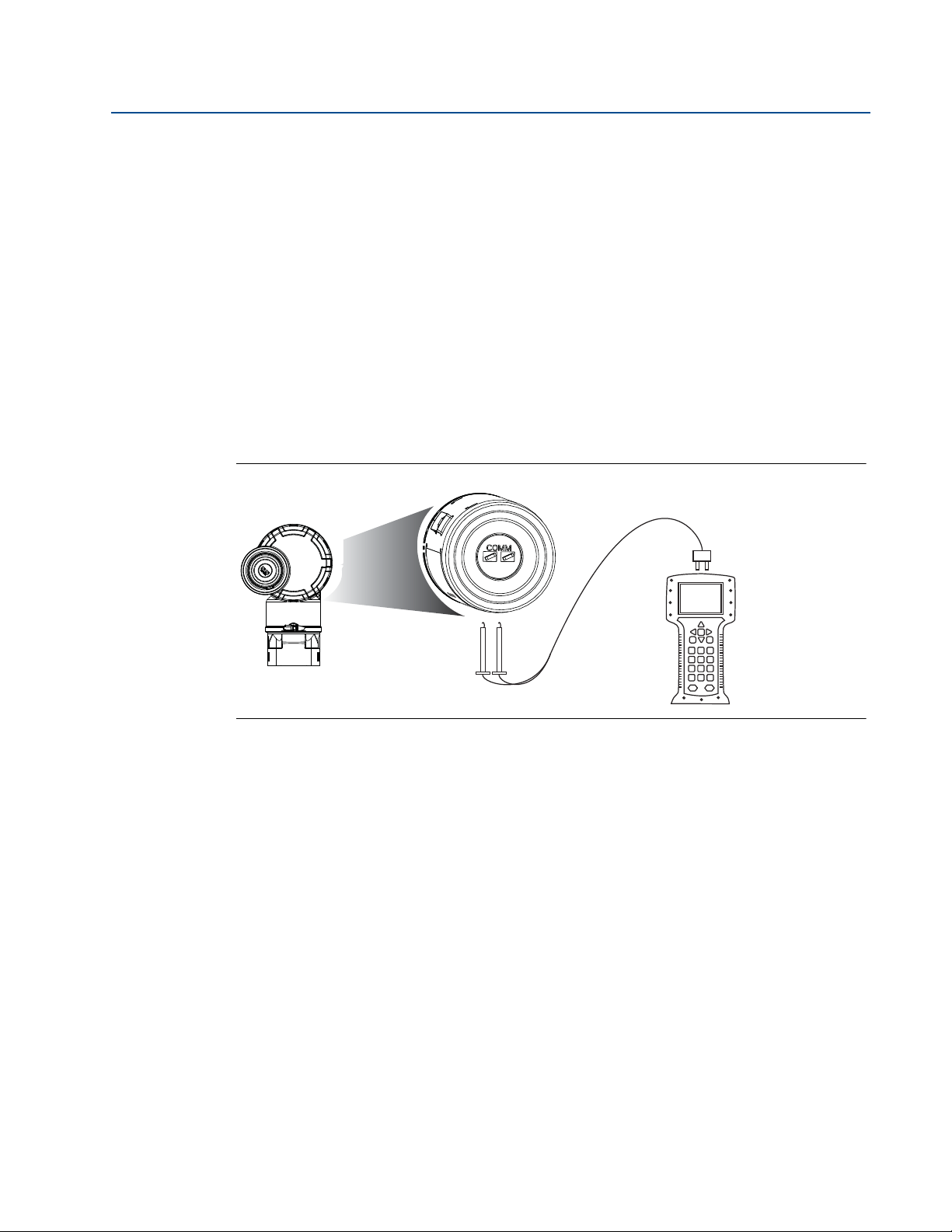
Field communicator connections
The Power Module needs to be installed in the device for the Field Communicator to interface
with the Rosemount 2051. The Field Communicator connections are located on the Power
Module. To communicate to the transmitter, connect the Field Communicator to the COMM
port connections on the Power Module. This transmitter uses the Green Power Module; please
order model number 701PGNKF. Field communication with this device requires a HART-based
Field Communicator using the correct Rosemount 2051 Wireless DD. The Power Module is
keyed and can only be inserted in one orientation. Refer to Figure 1-4 for instructions on
connecting the Field Communicator to the 2051.
Figure 1-4. Field Communicator Connections
Reference Manual
00809-0100-4102, Rev AA
1.5.2 Mechanical
Location
When choosing an installation location and position, take into account access to the power
module compartment for easy power module replacement.
Electronics cover
The electronics cover is tightened so that polymer contacts polymer. When removing the
electronics cover, ensure that there is no damage done to the o-ring. If damaged replace before
reattaching cover, ensuring polymer contacts polymer (i.e. no o-ring visible).
1.5.3 Electrical
Power module
The Rosemount 2051 Wireless Pressure Transmitter is self-powered. The Power Module
contains a primary lithium-thionyl chloride battery (Green Power Module, model number
6
Introduction
Page 19

Reference Manual
00809-0100-4102, Rev AA
701PGNKF). Each battery contains approximately 5 grams of lithium. Under normal conditions,
the battery materials are self-contained and are not reactive as long as the battery and the
Power Module are maintained. Care should be taken to prevent thermal, electrical, or
mechanical damage. Contacts should be protected to prevent premature discharge.
Use caution when handling the Power Module, it may be damaged if dropped from heights in
excess of 6.10 m (20 ft).
1.5.4 Environmental
Verify that the operating atmosphere of the transmitter is consistent with the appropriate
hazardous locations certifications.
Temperature effects
The transmitter will operate within specifications for ambient temperatures between -40 and 85
°C (-40 and 185 °F).
Heat from the process is transferred to the transmitter housing. If the process temperature is
high, the ambient temperature will need to be lower to account for heat transferred to the
transmitter housing. See “Process Temperature Limits” on page 96 for process temperature
derating.
Section 1: Introduction
May 2013
1.6 Service support
Within the United States, call the Emerson Process Management Instrument and Valve
Response Center using the 1-800-654-RSMT (7768) toll-free number. This center, available 24
hours a day, will assist you with any needed information or materials.
The center will ask for product model and serial numbers, and will provide a Return Material
Authorization (RMA) number. The center will also ask for the process material to which the
product was last exposed.
For inquiries outside of the United States, contact the nearest Emerson Process Management
representative for RMA instructions.
To expedite the return process outside of the United States, contact the nearest Emerson
Process Management representative.
Individuals who handle products exposed to a hazardous substance can avoid injury if they
are informed of and understand the hazard. The product being returned will require a copy
of the required Material Safety Data Sheet (MSDS) for each substance must be included
with the returned goods.
Introduction
7
Page 20

Section 1: Introduction
May 2013
Shipping considerations for wireless products (Lithium Batteries: Green Power Module,
model number 701PGNKF):
The unit was shipped to you without the Power Module installed. Please remove the Power
Module from the unit prior to shipping.
Each power module contains a primary lithium-thionyl chloride battery. Primary lithium
batteries are regulated in transportation by the U.S. Department of Transportation, and are
also covered by IATA (International Air Transport Association), ICAO (International Civil
Aviation Organization), and ARD (European Ground Transportation of Dangerous Goods). It
is the responsibility of the shipper to ensure compliance with these or any other local
requirements. Please consult current regulations and requirements before shipping.
The Power Module contains a primary lithium-thionyl chloride battery (Green Power Module,
model number 701PGNKF). Each Power Module contains approximately 5 grams of lithium.
Under normal conditions, the Power Module materials are self-contained and are not reactive as
long as the batteries and the module integrity are maintained. Care should be taken to prevent
thermal, electrical or mechanical damage. Contacts should be protected to prevent premature
discharge. Power Module hazards remain when cells are discharged.
Reference Manual
00809-0100-4102, Rev AA
Power Module should be stored in a clean and dry area. For maximum battery life, storage
temperature should not exceed 86 °F (30 °C).
Emerson Process Management Instrument and Valve Response Center representatives will
explain the additional information and procedures necessary to return goods exposed to
hazardous substances.
1.7 Product Recycling/Disposal
Recycling of equipment and packaging should be taken into consideration and disposed of in
accordance with local and national legislation/regulations.
8
Introduction
Page 21

Reference Manual
00809-0100-4102, Rev AA
Section 2 Configuration
Overview . . . . . . . . . . . . . . . . . . . . . . . . . . . . . . . . . . . . . . . . . . . . . . . . . . . . . . . . . . . . . . . page 9
Safety messages . . . . . . . . . . . . . . . . . . . . . . . . . . . . . . . . . . . . . . . . . . . . . . . . . . . . . . . . . page 9
Required bench top configuration . . . . . . . . . . . . . . . . . . . . . . . . . . . . . . . . . . . . . . . . . page 10
Basic setup . . . . . . . . . . . . . . . . . . . . . . . . . . . . . . . . . . . . . . . . . . . . . . . . . . . . . . . . . . . . . . page 11
Review configuration data . . . . . . . . . . . . . . . . . . . . . . . . . . . . . . . . . . . . . . . . . . . . . . . . page 20
Review operating parameters . . . . . . . . . . . . . . . . . . . . . . . . . . . . . . . . . . . . . . . . . . . . . page 21
Review operating parameters . . . . . . . . . . . . . . . . . . . . . . . . . . . . . . . . . . . . . . . . . . . . . page 21
Configuring the LCD display . . . . . . . . . . . . . . . . . . . . . . . . . . . . . . . . . . . . . . . . . . . . . . . page 22
Configuring the LCD display . . . . . . . . . . . . . . . . . . . . . . . . . . . . . . . . . . . . . . . . . . . . . . . page 22
Detailed transmitter setup . . . . . . . . . . . . . . . . . . . . . . . . . . . . . . . . . . . . . . . . . . . . . . . . page 23
Diagnostics and service . . . . . . . . . . . . . . . . . . . . . . . . . . . . . . . . . . . . . . . . . . . . . . . . . . . page 24
Advanced Functions for HART Protocol . . . . . . . . . . . . . . . . . . . . . . . . . . . . . . . . . . . . . page 27
Section 2: Configuration
May 2013
2.1 Overview
This section contains information on commissioning and tasks that should be performed on the
bench prior to installation.
Field Communicator and AMS Device Manager instructions are given to perform configuration
functions. For convenience, Field Communicator fast key sequences are labeled “Fast Keys” for
each software function below the appropriate headings.
Full Field Communicator menu trees and fast key sequences are available in Appendix C: Field
Communicator Menu Trees and Fast Keys.
2.2 Safety messages
Procedures and instructions in this section may require special precautions to ensure the safety
of the personnel performing the operations. Information that raises potential safety issues is
indicated by a warning symbol ( ). Refer to the following safety messages before performing
an operation preceded by this symbol.
9Configuration
Page 22

Section 2: Configuration
May 2013
Warnings ( )
Failure to follow these installation guidelines could result in death or
serious injury.
Make sure only qualified personnel perform the installation.
Explosions could result in death or serious injury:
Installation of this transmitter in an explosive environment must be in accordance with the
appropriate local, national, and international standards, codes, and practices. Please review
the approvals section of the 2051 Wireless reference manual for any restrictions associated
with a safe installation.
Before connecting a Field Communicator in an explosive atmosphere, make sure the
Verify that the operating atmosphere of the transmitter is consistent with the
Process leaks could result in death or serious injury.
Install and tighten process connectors before applying pressure.
Electrical shock could cause death or serious injury.
Avoid contact with the leads and terminals. High voltage that may be present on leads
This device complies with Part 15 of the FCC Rules. Operation is subject to the following
conditions: This device may not cause harmful interference. This device must accept any
interference received, including interference that may cause undesired operation.
This device must be installed to ensure a minimum antenna separation distance of
Reference Manual
00809-0100-4102, Rev AA
instruments are installed in accordance with intrinsically safe or non-incendive field
wiring practices.
appropriate hazardous locations certifications
can cause electrical shock.
20cm (8 in.) from all persons.
2.3 Required bench top configuration
Bench top configuration requires a Field Communicator, AMS, or any WirelessHART
Communicator. Connect the Field Communicator leads to the terminals labeled “COMM” on the
Power Module. See Figure 2-1 on page 11.
Bench top configuration consists of testing the transmitter and verifying transmitter
configuration data. 2051 Wireless transmitters must be configured before installation.
Configuring the transmitter on the bench before installation using a Field Communicator, AMS,
or any WirelessHART Communicator ensures that all network settings are working correctly.
When using a Field Communicator, any configuration changes made must be sent to the
transmitter by using the “Send” key (F2). AMS configuration changes are implemented when
the “Apply” button is clicked.
AMS Wireless Configurator
AMS is capable of connecting to devices either directly, using a HART modem, or wirelessly via
the Smart Wireless Gateway. When configuring the device, double click the device icon or right
click and select Configure.
10
Configuration
Page 23
Reference Manual
00809-0100-4102, Rev AA
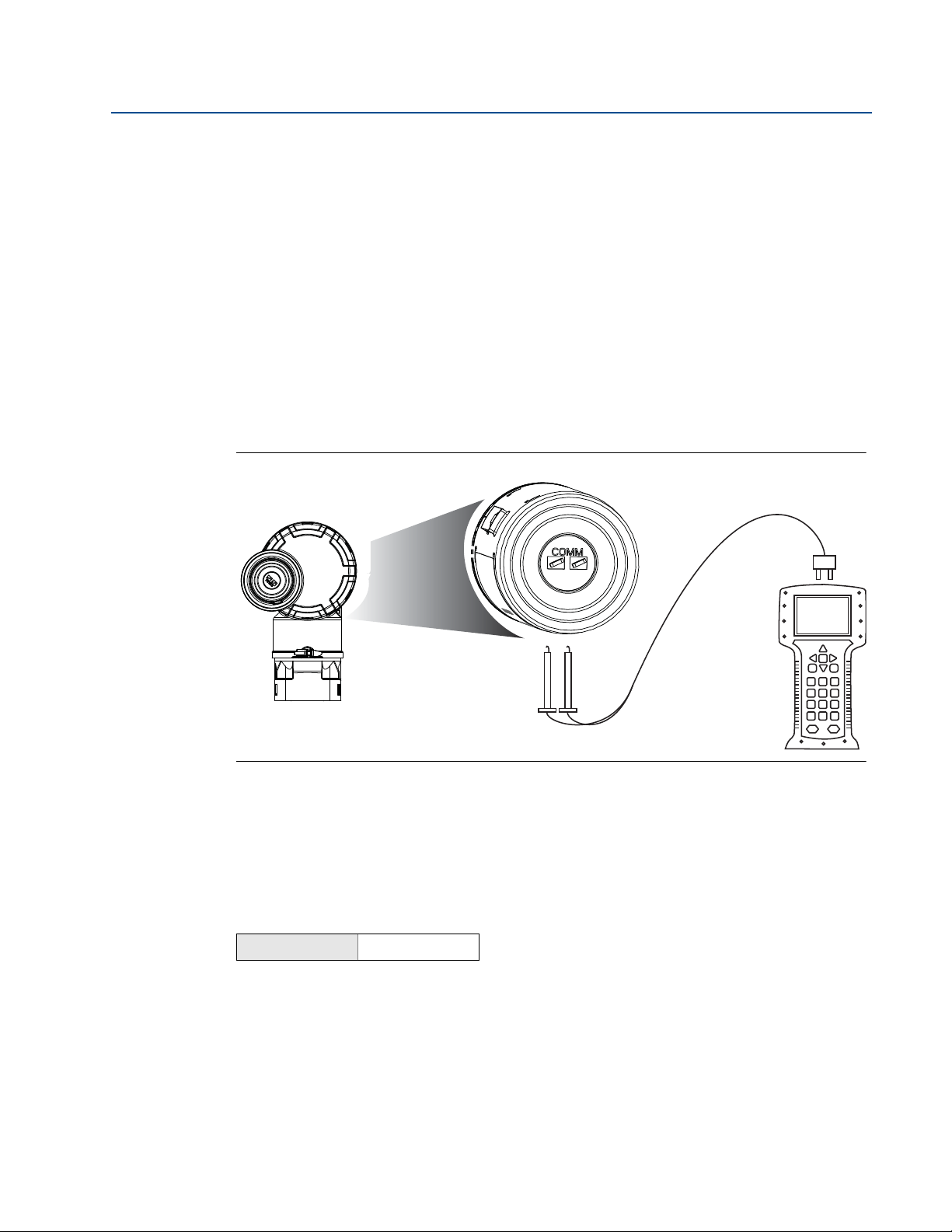
2.3.1 Connection diagrams
Bench hook-up
Connect the bench equipment as shown in Figure 2-1 on page 11, and turn on the Field
Communicator by pressing the ON/OFF key or log into AMS. The Field Communicator or AMS
will search for a HART-compatible device and indicate when the connection is made. If the Field
Communicator or AMS fail to connect, it indicates that no device was found. If this occurs, refer
to Section 6: Troubleshooting.
Field hook-up
Figure 2-1 on page 11 illustrates the wiring for a field hook-up with a Field Communicator or
AMS. The Field Communicator or AMS may be connected at “COMM” on the transmitter Power
Module.
Figure 2-1. Field Communicator Connection
Section 2: Configuration
May 2013
For HART communication, a 2051 WirelessHART DD is required.
2.4 Basic setup
2.4.1 Set device tag
Fast Keys
The tag is used to identify the device. You can use an 8 to 32 character tag.
1. From the Home screen, select 2: Configure
2. Select 2: Manual Setup
3. Select 9: Device Information
4. Select 1: Identification
Configuration
5. Select 1: Tag
2, 2, 9, 1, 1
11
Page 24

Section 2: Configuration
May 2013
2.4.2 Join device to network
Reference Manual
00809-0100-4102, Rev AA
Fast Keys
In order to communicate with the Smart Wireless Gateway, and ultimately the Host System, the
transmitter must be configured to communicate over the wireless network. This step is the
wireless equivalent of connecting wires from a transmitter to the host system.
1. From the Home screen, select 2: Configure.
2. Select 1: Guided Setup.
3. Select 3: Join Device to Network.
Using a Field Communicator or AMS, enter the Network ID and Join Key so that they match the
Network ID and Join Key of the Smart Wireless Gateway and other devices in the network. If the
Network ID and Join Key are not identical to those set in the Gateway, the transmitter will not
communicate with the network. The Network ID and Join Key may be obtained from the Smart
Wireless Gateway on the Setup>Network>Settings page on the web server.
2, 1, 3
2.4.3 Configure update rate
Fast Keys
The Update Rate is the frequency at which a new measurement is taken and transmitted over
the wireless network. This by default is 1 minute. This may be changed at commissioning, or at
any time via AMS Wireless Configurator. The Update Rate is user selectable from 1 second to 60
minutes.
2, 1, 4
1. From the Home screen, select 2: Configure.
2. Select 1: Guided Setup.
3. Select 4: Configure Update Rate.
12
Configuration
Page 25

Reference Manual
00809-0100-4102, Rev AA
2.4.4 Set process variable units
Section 2: Configuration
May 2013
Fast Keys
2, 2, 2, 3
The PV Unit command sets the process variable units to allow you to monitor your process using
the appropriate units of measure.
To select a unit of measure for the PV:
1. From the Home screen, select 2: Configure.
2. Select 2: Manual Setup.
3. Select 2: Pressure.
4. Select 3: Unit to select from the following engineering units:
inH
inH
inH
ftH
O at 4 °C mmH2O at 68 °F mmHg Mpa
2
O at 60 °F cmH2O at 4 °C Psi Bar
2
O at 68 °F mH2O at 4 °C Atm Mbar
2
O at 4 °C inHg at 0 °C To rr g/cm
2
ftH2O at 60 °F mmHg at 0 °C Pascals kg/cm
ftH2O at 68 °F cmHg at 0 °C hectoPascals kg/m
mmH2O at 4 °C mHg at 0 °C Kilopascals
2.4.5 Remove Power Module
2
2
2
After the sensor and network have been configured, remove the Power Module and replace the
housing cover. The Power Module should be inserted only when the device is ready to be
commissioned.
Use caution when handling the Power Module. The Power Module may be damaged if dropped
from heights in excess of 6.10 m (20 ft).
2.5 Configure for Pressure
2.5.1 Re-Mapping device variables
The re-mapping function allows the transmitter primary, secondary, tertiary, and quaternary
variables (PV, SV, TV, and QV) to be configured in one of two configurations. The user may select
either the option of Classic mapping or Scaled Variable Mapping, see Tab l e 2 -1 for what is
mapped to each variable. All variables can be remapped with a Field Communicator or AMS
Device Manager.
Configuration
13
Page 26

Section 2: Configuration
May 2013
Table 2-1. Variable Mapping
PV Pressure Scaled Variable
SV Sensor Temperature Pressure
TV Electronics Temperature Sensor Temperature
QV Supply Voltage Supply Voltage
Note
The variable assigned to the primary variable drives the output. This value can be selected as
Pressure or Scaled Variable.
Re-mapping using a Field Communicator
From the HOME screen, enter the fast key sequence
Fast Keys
Reference Manual
00809-0100-4102, Rev AA
Classic Mapping Scaled Variable Mapping
2, 2, 6, 1
Re-mapping using AMS Device Manager
Right click on the device and select Configure.
1. Select Manual Setup and click on the HART tab.
2. Assign Primary, secondary, tertiary and quaternary variables under Variable Mapping.
3. Click Send.
4. Carefully read the warning and click Yes if it is safe to apply the changes.
2.5.2 Set range points
From the HOME screen, enter the fast key sequence
Fast Keys
The Range Values command sets the lower and upper range values used for the percent of range
measurement.
Note
Transmitters are shipped from Rosemount Inc. fully calibrated per request or by the factory
default of full scale (span = upper range limit).
2, 1, 1, 5
14
1. From the Home screen, select 2: Configure
2. Select 1: Guided Setup
3. Select 1: Basic Setup
4. Select 5: Range Values
Configuration
Page 27
Reference Manual
Sq. Root
Curve
Transition Point
Linear Section
Slope=1
Slope=42
Transitio n Poi nt
Sq. Root Curve
Full Scale
Flow (%)
00809-0100-4102, Rev AA
Section 2: Configuration
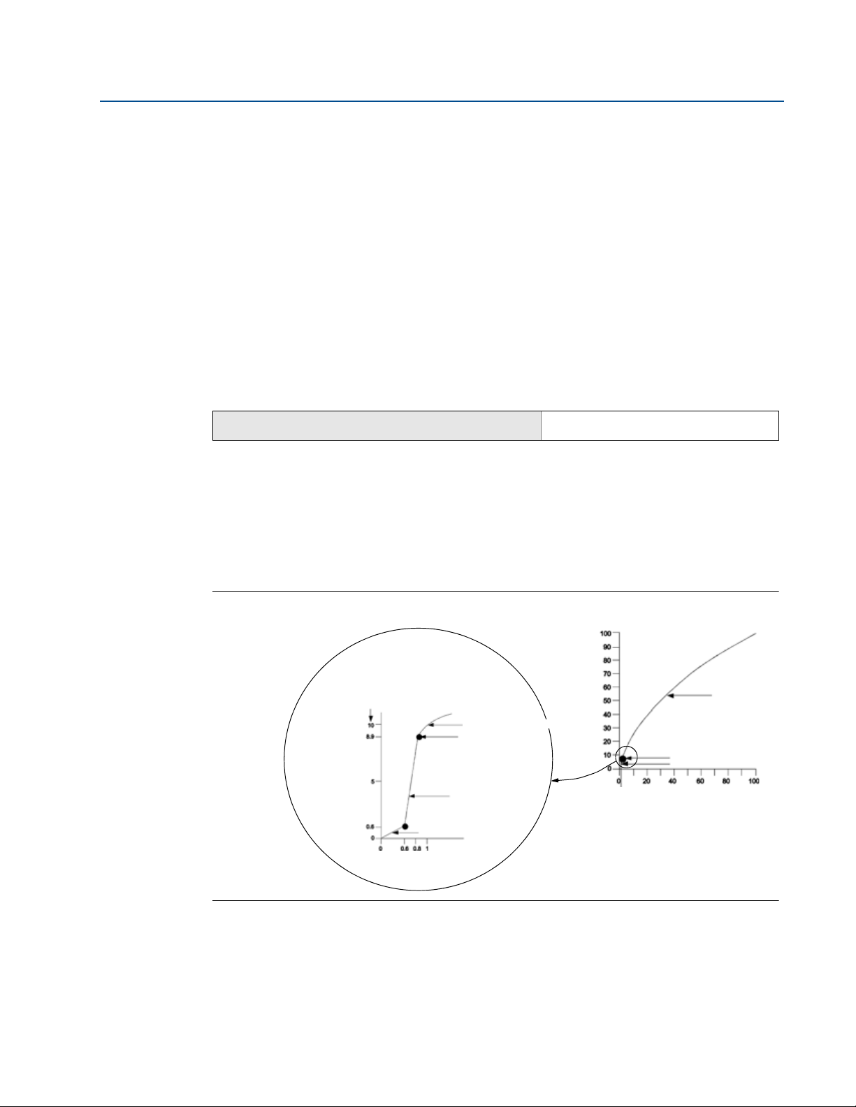
2.5.3 Set transmitter percent of range (transfer function)
The Rosemount 2051 Wireless transmitter has two transfer functions for pressure applications:
Linear and Square Root. As shown in Figure 2-2 on page 15, activating the square root options
the transmitter analog output proportional to flow.
However, for DP Flow and DP Level applications it is recommended to use Scaled Variable. Refer
to “Diagnostics and service” on page 24 for setup instructions.
From 0 to 0.6 percent of the ranged pressure input, the slope of the curve is unity (y = x). This
allows accurate calibration near zero. Greater slopes would cause large changes in output (for
small changes at input). From 0.6 percent to 0.8 percent, curve slope equals 42 (y = 42x) to
achieve continuous transition from linear to square root at the transition point.
Setting transmitter output with a Field Communicator
From the HOME screen, enter the fast key sequence
Fast Keys
2, 2, 4, 2
May 2013
Setting transmitter output with AMS Device Manager
Right click on the device and select Configure.
1. Click Manual Setup and choose output type from Transfer Fu nc tion and click Send.
2. Carefully read the warning and click Yes if it is safe to apply the changes.
Figure 2-2. Square Root Output Transition Point
Configuration
15
Page 28

Section 2: Configuration
May 2013
2.6 Configure for Level and Flow
2.6.1 Configuring scaled variable
The Scaled Variable configuration allows the user to create a relationship/conversion between
the pressure units and user-defined/custom units. There are two use cases for Scaled Variable.
The first use case is to allow custom units to be displayed on the transmitter's LCD Display. The
second use case is to allow custom units to drive the transmitter's PV output.
If the user desires custom units to drive the PV output, Scaled Variable must be re-mapped as
the primary variable. Refer to “Re-Mapping device variables” on page 18.
The Scaled Variable configuration defines the following items:
Scaled Variable units - Custom units to be displayed.
Scaled data options - Defines the transfer function for the application
– Linear
– Square root
Reference Manual
00809-0100-4102, Rev AA
Pressure value position 1 - Lower known value point with consideration of linear offset.
Scaled Variable value position 1 - Custom unit equivalent to the lower known value
point.
Pressure value position 2 - Upper known value point
Scaled Variable value position 2 - Custom unit equivalent to the upper known value
point
Linear offset - The value required to zero out pressures affecting the desired pressure
reading.
Low flow cutoff - Point at which output is driven to zero to prevent problems caused by
process noise. It is highly recommended to use the low flow cutoff function in order to
have a stable output and avoid problems due to process noise at a low flow or no flow
condition. A low flow cutoff value that is practical for the flow element in the
application should be entered.
Configuring Scaled Variable using a Field Communicator
From the HOME screen, enter the fast key sequence
Device Dashboard Fast Keys
1. Follow the screen prompts to configure Scaled Variable.
a. When configuring for level, select Linear under Select Scaled data options.
b. When configuring for flow, select Square Root under Select Scaled data options.
2, 1, 7
16
Configuring Scaled Variable using AMS Device Manager
Right click on the device and, select Configure.
1. Select the Scaled Variable tab and click the Scaled Variable button.
2. Follow screen prompts to configure Scaled Variable
Configuration
Page 29
Reference Manual
H
L
A
B
C
D
00809-0100-4102, Rev AA
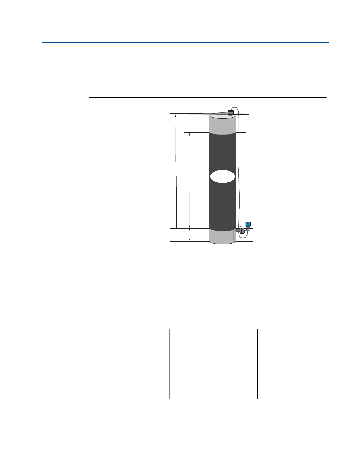
DP Level Example
Figure 2-3. Example tank
Section 2: Configuration
May 2013
a. When configuring for level applications, select Linear under Select Scaled data options.
b. When configuring for flow applications, select Square Root under Select Scaled data
options.
A. 230 in.
B. 200 in.
C. 12 in.
D. 0.94 sg
A differential transmitter is used in a level application. Once installed on an empty tank and taps
vented, the process variable reading is -209.4 inH2O. The process variable reading is the head
pressure created by fill fluid in the capillary. Based on Table 2-2 on page 2-17, the Scaled
Variable configuration would be as follows:
Table 2-2. Scaled Variable Configuration for Tank Application
Scaled Variable units: inch
Scaled data options: linear
Pressure value position 1: 0 inH2O
Scaled Variable position 1: 12 in.
Pressure value position 2: 188 inH2O
Scaled Variable position 2: 212 in.
Linear offset: -209.4 inH2O
DP Flow example
Configuration
A differential pressure transmitter is used in conjunction with an orifice plate in a flow
application where the differential pressure at full scale flow is 125 inH2O. In this particular
application, the flow rate at full scale flow is 20,000 gallons of water per hour. It is highly
17
Page 30

Section 2: Configuration
May 2013
recommended to use the low flow cutoff function in order to have a stable output and avoid
problems due to process noise at a low flow or no flow condition. A low flow cutoff value that is
practical for the flow element in the application should be entered. In this particular example,
the low flow cutoff value is 1000 gallons of water per hour. Based on this information, the Scaled
Variable configuration would be as follows:
Table 2-3. Scaled Variable Configuration for Flow Application
Scaled Variable units: gal/h
Scaled data options: square root
Pressure value position 2: 125 inH2O
Scaled Variable position 2: 20,000 gal/h
Low Flow Cutoff: 1000 gal/h
Note
Pressure value position 1 and Scaled Variable position 1 are always set to zero for a flow
application. No configuration of these values is required.
Reference Manual
00809-0100-4102, Rev AA
2.6.2 Re-Mapping device variables
The re-mapping function allows the transmitter primary, secondary, tertiary, and quaternary
variables (PV, SV, TV, and QV) to be configured in one of two configurations. The user may select
either the option of Classic Mapping or Scaled Variable Mapping, see Ta bl e 2 - 4 for what is
mapped to each variable. All variables can be remapped with a Field Communicator or AMS
Device Manager.
Table 2-4. Variable Mapping
Classic Mapping Scaled Variable Mapping
PV Pressure Scaled Variable
SV Sensor Temperature Pressure
TV Electronics Temperature Sensor Temperature
QV Supply Voltage Supply Voltage
Note
The variable assigned to the primary variable drives the output. This value can be selected as
Pressure or Scaled Variable.
Re-mapping using a Field Communicator
18
From the HOME screen, enter the fast key sequence
Fast Keys
Re-mapping using AMS Device Manager
Right click on the device and select Configure.
2, 2, 6, 1, 1
Configuration
Page 31

Reference Manual
00809-0100-4102, Rev AA
1. Select Manual Setup and click on the HART tab.
2. Assign Primary, secondary, tertiary and quaternary variables under Variable Mapping.
3. Click Send.
4. Carefully read the warning and click Yes if it is safe to apply the changes.
2.6.3 Set range points
From the HOME screen, enter the fast key sequence
Fast Keys
The Range Values command sets the lower and upper range values used for the percent of range
measurement.
Note
Transmitters are shipped from Rosemount Inc. fully calibrated per request or by the factory
default of full scale (span = upper range limit).
Section 2: Configuration
May 2013
2, 1, 1, 5
1. From the Home screen, select 2: Configure
2. Select 1: Guided Setup
3. Select 1: Basic Setup
4. Select 5: Range Values
Configuration
19
Page 32

Section 2: Configuration
May 2013
2.7 Review configuration data
The following is a list of factory default configurations that can be viewed by using the Field
Communicator or AMS. Follow the steps below to review the transmitter configuration
information.
Note
Information and procedures in this section that make use of Field Communicator fast key
sequences and AMS assume that the transmitter and communication equipment are
connected, powered, and operating correctly.
2.7.1 Review pressure information
Reference Manual
00809-0100-4102, Rev AA
Fast Keys
2, 2, 2
To view pressure information:
1. From the Home screen, select 2: Configure.
2. Select 2: Manual Setup.
3. Select 2: Pressure.
4. Select from the corresponding number to view each field:
1 Pressure
2 Pressure Status
3 Units
4 Damping
2.7.2 Review device information
Fast Keys
To view device information:
1. From the Home screen, select 2: Configure.
2, 2, 9
20
2. Select 2: Manual Setup.
3. Select 9: Device Information.
4. Select from the corresponding number to view each field:
1 Identification
2 Revisions
3 Radio
4 Sensor Information
5 Flange Information
6 Remote Seal
Configuration
Page 33

Reference Manual
00809-0100-4102, Rev AA
2.7.3 Review radio information
Section 2: Configuration
May 2013
Fast Keys
1, 7, 3
To vie w r a dio informat ion:
1. From the Home screen, select 1: Overview.
2. Select 7: Device Information.
3. Select 3: Radio.
4. Select from the corresponding number to view each field:
1 Manufacturer
2 Device Type
3 Device Revision
4 Software Revision
5 Hardware Revision
6 Tra nsmi t Po wer Level
7 Minimum Update Rate
2.7.4 Review operating parameters
Fast Keys
3, 2
The pressure output value in both engineering units and percent of range will reflect the applied
pressure even when the applied pressure is outside of the configured range as long as the
applied pressure is between the upper and lower range limit of the transmitter. For example, if a
Range 2 2051T (LRL = 0 psi, URL = 150 psi) is ranged from 0 to 100 psi, an applied pressure of
150 psi will return a % of range output of 150% and an engineering output of 150 psi.
To v i ew the Operating Parameters menu:
1. From the Home screen, select 3: Service Tools.
2. Select 2: Variables.
The Operating Parameters menu displays the following information pertaining to the device:
1. Process
Pressure
Percent of Range
Last Update Time
Scaled Variable
Enter Fast Update Mode
2. Device
Sensor Temperature
Supply Voltage
Configuration
21
Page 34

Section 2: Configuration
May 2013
2.8 Configuring the LCD display
The LCD Display configuration command allows customization of the LCD to suit application
requirements. The LCD will alternate between the selected items.
Pressure Units Sensor Temperature
% of Range Supply Voltage
Scaled Variable
In the following instructions, the LCD can also be configured to display configuration
information during the device startup. Select Review Parameters at Startup to enable or
disable this functionality.
Reference Figure 1-2 on page 4 LCD with Local Operator Interface for image of LCD screen.
Configuring LCD display with a Field Communicator
From the HOME screen, enter the fast key sequence
Device Dashboard Fast Keys
Reference Manual
00809-0100-4102, Rev AA
2, 2, 5
Configuring LCD display with AMS Device Manager
Right click on the device and select Configure.
1. Click Manual Setup, select the Display tab.
2. Select desired display options and click Send.
22
Configuration
Page 35

Reference Manual
Deadband
Assigned Value
Alert Set Point
Alert “OFF” Alert “ON” Alert “OFF”
Units of Measurement
Time
Deadband
Assigned Value
Alert Set Point
Alert “OFF” Alert “ON” Alert “OFF”
Units of Measurement
Time
00809-0100-4102, Rev AA
2.9 Detailed transmitter setup
2.9.1 Configure process alerts
Section 2: Configuration
May 2013
Fast Keys
Process alerts allow the transmitter to indicate when the configured data point is exceeded.
Process alerts can be set for pressure, temperature, or both. An alert will be displayed on a Field
Communicator, AMS Device Manager status screen or in the error section of the LCD Display.
The alert will reset once the value returns within range.
Note
HI alert value must be higher than the LO alert value. Both alert values must be within the
pressure or temperature sensor limits.
Example 1: Rising Alert
Example 2: Falling Alert
2, 1, 6
To configure the process alerts, perform the following procedure:
1. From the Home screen, select 2: Configure.
2. Select 1: Guided Setup.
3. Select 6: Configure Process Alerts and follow the on-screen instructions to complete
configure of process alarms.
2.9.2 Damping
The Damping command introduces a delay in processing which increases the response time of
the transmitter; smoothing variations in output readings caused by rapid input changes. In the
Configuration
23
Page 36

Section 2: Configuration
May 2013
2051 Wireless pressure transmitter, damping only takes effect when the device is placed in high
power refresh mode and during calibration. In normal power mode, the effective damping is 0.
Note that when the device is in high power refresh mode, battery power will be depleted rapidly.
Determine the appropriate damp setting based on the necessary response time, signal stability,
and other requirements of the loop dynamics of your system. The damping value of your device
is user selectable from 0 to 60 seconds.
Damping with a Field Communicator
From the HOME screen, enter the fast key sequence
Device Dashboard Fast Keys
Enter desired Damping Value and select APPLY.
Damping with AMS Device Manager
Right click on the device and select Configure.
1. Select Manual Setup.
Reference Manual
00809-0100-4102, Rev AA
2, 2, 2, 4
2. Within the Pressure Setup box, enter desired damping value and click Send.
3. Carefully read the warning and click Yes if it is safe to apply the changes.
2.9.3 Write protect
The Rosemount 2051 Wireless pressure transmitter has a software write protect security
feature.
Enabling write protect with a Field Communicator
From the HOME screen, enter the fast key sequence
Device Dashboard Fast Keys
Select Write Protect to enable.
Enabling write protect with AMS Device Manager
Right click on device and select Configure.
1. Select Manual Setup.
2. Select the tab labeled Device Information.
2, 2, 7, 1
3. Select Write Protect to enable this feature.
2.10 Diagnostics and service
Diagnostics and service functions listed below are primarily for use after field installation. The
Transmitter Test feature is designed to verify that the transmitter is operating properly, and can
be performed either on the bench or in the field.
24
Configuration
Page 37

Reference Manual
00809-0100-4102, Rev AA
2.10.1 Device reset
The master reset function will reset the device electronics. To perform a device reset:
Performing master reset using a Field Communicator
From the HOME screen, enter the fast key sequence
Section 2: Configuration
May 2013
Device Dashboard Fast Keys
Performing master reset using AMS Device Manager
1. From the Home screen, select 3: Service Tools.
2. Select 5: Maintenance
3. Select 5: Device Reset
2.10.2 Join status
Viewing join status using a Field Communicator
From the HOME screen, enter the fast key sequence
Device Dashboard Fast Keys
Viewing join status using AMS Device Manager
To view the join status of the device, perform the following procedure:
1. From the Home screen, select 3: Service Tools.
3, 5, 5
3, 4, 1
Configuration
2. Select 4: Communications.
3. Select 1: Join Status.
Wireless devices join the secure network through a four step process:
Step 1. Network Found
Step 2. Network Security Clearance Granted
Step 3. Network Bandwidth Allocated
Step 4. Network Join Complete
25
Page 38

Section 2: Configuration
May 2013
2.10.3 Number of available neighbors
Viewing number of available neighbors using a Field
Communicator
From the HOME screen, enter the fast key sequence
Device Dashboard Fast Keys
Viewing number of available neighbors using AMS Device
Manager
In a self-organizing network, the more neighbors a device has, the more robust the network will
be. To view the number of available neighbors for the wireless device, perform the following
procedure:
1. From the Home screen, select 3: Service Tools.
2. Select 4: Routine Maintenance.
Reference Manual
00809-0100-4102, Rev AA
3, 4, 3
3. Select 3: Number of Available Neighbors.
26
Configuration
Page 39

Reference Manual
00809-0100-4102, Rev AA
Section 2: Configuration
2.11 Advanced Functions for HART Protocol
2.11.1 Saving, Recalling, and Cloning Configuration Data
May 2013
Fast Keys
Use the cloning feature of the Field Communicator or the AMS “User Configuration” feature to
configure several 2051 Wireless transmitters similarly. Cloning involves configuring a
transmitter, saving the configuration data, then sending a copy of the data to a separate
transmitter. Several possible procedures exist when saving, recalling, and cloning configuration
data. For complete instructions refer to the Field Communicator manual (publication no.
00809-0100-4276) or AMS Books Online. One common method is as follows:
left arrow, 1, 2
Field Communicator
1. Completely configure the first transmitter.
2. Save the configuration data:
a. Select F2 SAVE from the Field Communicator HOME/ONLINE screen.
b. Ensure that the location to which the data will be saved is set to MODULE. If it is not,
select 1: Location to set the save location to MODULE.
c. Select 2: Name, to name the configuration data. The default is the transmitter tag
number.
d. Ensure that the data type is set to STANDARD. If the data type is NOT
select 3: Data Type to set the data type to STANDARD.
e. Select F2 SAVE.
STANDARD,
3. Connect and power the receiving transmitter and Field Communicator.
4. Select the back arrow from the HOME/ONLINE screen. The Field Communicator menu
appears.
5. Select 1: Offline, 2: Saved Configuration, 1: Module Contents to reach the MODULE
CONTENTS menu.
6. Use the DOWN ARROW to scroll through the list of configurations in the memory
module, and use the RIGHT ARROW to select and retrieve the required configuration.
7. Select 1: Edit.
8. Select 1: Mark All.
9. Select F2 SAVE.
10. Use the DOWN ARROW to scroll through the list of configurations in the memory
module, and use the RIGHT ARROW to select the configuration again.
11. Select 3: Send to download the configuration to the transmitter.
12. Select OK after the control loop is set to manual.
13. After the configuration has been sent, select OK.
Configuration
27
Page 40

Section 2: Configuration
May 2013
When finished, the Field Communicator informs you of the status. Repeat Steps 3 through 13 to
configure another transmitter.
Note
The transmitter receiving cloned data must have the same software version (or later) as the
original transmitter.
AMS creating a Reusable Copy
To create a reusable copy of a configuration perform the following procedure:
1. Completely configure the first transmitter.
2. Select View then User Configuration View from the menu bar (or click the toolbar
3. In the User Configuration window, right click and select New from the context menu.
4. In the New window, select a device from the list of templates shown, and click OK.
Reference Manual
00809-0100-4102, Rev AA
button).
5. The template is copied into the User Configurations window, with the tag name
highlighted; rename it as appropriate and press Enter.
Note
A device icon can also be copied by dragging and dropping a device template or any other
device icon from AMS Explorer or Device Connection View into the User Configurations window.
The “Compare Configurations” window appears, showing the Current values of the copied
device on one side and mostly blank fields on the other (User Configuration) side.
6. Transfer values from the current configuration to the user configuration as appropriate
or enter values by typing them into the available fields.
7. Click Apply to apply the values, or click OK to apply the values and close the window.
AMS Applying a User Configuration
Any amount of user configurations can be created for the application. They can also be saved,
and applied to connected devices or to devices in the Device List or Plant Database.
To apply a user configuration perform the following procedure:
1. Select the desired user configuration in the User Configurations window.
2. Drag the icon onto a like device in AMS Explorer or Device Connection View. The
Compare Configurations window opens, showing the parameters of the target device
on one side and the parameters of the user configuration on the other.
28
3. Transfer parameters from the user configuration to the target device as desired, Click
OK to apply the configuration and close the window.
Configuration
Page 41

Reference Manual
00809-0100-4102, Rev AA
Section 3 Installation
Overview . . . . . . . . . . . . . . . . . . . . . . . . . . . . . . . . . . . . . . . . . . . . . . . . . . . . . . . . . . . . . . . page 29
Safety messages . . . . . . . . . . . . . . . . . . . . . . . . . . . . . . . . . . . . . . . . . . . . . . . . . . . . . . . . . page 29
Considerations . . . . . . . . . . . . . . . . . . . . . . . . . . . . . . . . . . . . . . . . . . . . . . . . . . . . . . . . . . page 31
Installation procedures . . . . . . . . . . . . . . . . . . . . . . . . . . . . . . . . . . . . . . . . . . . . . . . . . . . page 35
Installing the LCD display . . . . . . . . . . . . . . . . . . . . . . . . . . . . . . . . . . . . . . . . . . . . . . . . . page 46
Rosemount 304, 305 and 306 integral manifolds . . . . . . . . . . . . . . . . . . . . . . . . . . . . page 47
3.1 Overview
The information in this section covers installation considerations. A Quick Installation Guide
(document number 00825-0100-4102) is shipped with every transmitter to describe basic
installation and startup procedures. Dimensional drawings for each Rosemount 2051 Wireless
variation and mounting configuration are included in Appendix A: Specifications and Reference
Data.
Section 3: Installation
May 2013
Note
For transmitter disassembly refer to 6.3: Removing from service on page 88.
3.2 Safety messages
Procedures and instructions in this section may require special precautions to ensure the safety
of the personnel performing the operation. Information that raises potential safety issues is
indicated with a warning symbol ( ). Refer to the following safety messages before
performing an operation preceded by this symbol.
Installation
29
Page 42

Section 3: Installation
May 2013
3.2.1 Warnings ( )
Failure to follow these installation guidelines could result in death or
serious injury.
Make sure only qualified personnel perform the installation.
Explosions could result in death or serious injury:
Installation of this transmitter in an explosive environment must be in accordance with the
appropriate local, national, and international standards, codes, and practices. Please review
the approvals section of the 2051 Wireless reference manual for any restrictions associated
with a safe installation.
Before connecting a Field Communicator in an explosive atmosphere, make sure the
instruments are installed in accordance with intrinsically safe or non-incendive field
wiring practices.
Verify that the operating atmosphere of the transmitter is consistent with the
appropriate hazardous locations certifications
Process leaks could result in death or serious injury.
Install and tighten process connectors before applying pressure.
Electrical shock could cause death or serious injury.
Avoid contact with the leads and terminals. High voltage that may be present on leads
can cause electrical shock.
This device complies with Part 15 of the FCC Rules. Operation is subject to the following
conditions: This device may not cause harmful interference. This device must accept any
interference received, including interference that may cause undesired operation.
This device must be installed to ensure a minimum antenna separation distance of 20
cm (8 in.) from all persons.
Reference Manual
00809-0100-4102, Rev AA
30
Installation
Page 43

Reference Manual
00809-0100-4102, Rev AA
Section 3: Installation
May 2013
Electrical shock can result in death or serious injury.
Avoid contact with the leads and terminals.
Process leaks could result in death or serious injury.
Install and tighten all four flange bolts before applying pressure.
Do not attempt to loosen or remove flange bolts while the transmitter is in service.
Replacement equipment or spare parts not approved by Emerson Process Management for
use as spare parts could reduce the pressure retaining capabilities of the transmitter and
may render the instrument dangerous.
Use only bolts supplied or sold by Emerson Process Management as spare parts.
Improper assembly of manifolds to traditional flange can damage sensor module.
For safe assembly of manifold to traditional flange, bolts must break back plane of
flange web (i.e., bolt hole) but must not contact sensor module housing.
The Power Module with the wireless unit contains a primary lithium-thionyl chloride
battery. Each Power Module contains approximately 5.0 grams of lithium. Under normal
conditions, the Power Module materials are self-contained and are not reactive as long as
the batteries and the pack integrity are maintained. Care should be taken to prevent
thermal, electrical or mechanical damage. Contacts should be protected to prevent
premature discharge.
3.3 Considerations
3.3.1 Installation considerations
Measurement performance depends upon proper installation of the transmitter and impulse
piping. Mount the transmitter close to the process and use a minimum of piping to achieve best
performance. Also, consider the need for easy access, personnel safety, practical field
calibration, and a suitable transmitter environment. Install the transmitter to minimize
vibration, shock, and temperature fluctuation.
3.3.2 Wireless considerations
Power up sequence
The Power Module should not be installed on any wireless device until the Smart Wireless
Gateway is installed and functioning properly. This transmitter uses the Green Power Module
(order model number 701PGNKF). Wireless devices should also be powered up in order of
proximity from the Smart Wireless Gateway, beginning with the closest. This will result in a
simpler and faster network installation. Enable Active Advertising on the Gateway to ensure that
new devices join the network faster. For more information, see the Smart Wireless Gateway
Manual (Doc. No. 00809-0200-4420).
Installation
31
Page 44

Section 3: Installation
May 2013
Internal antenna position
The internal antenna is designed for multiple mounting orientations. The transmitter should be
mounted according to measurement best practices for your pressure measurement application.
The antenna should be approximately 3 ft (1 m) from any large structure or building to allow
clear communication to other devices.
Field communicator connections
In order for the Field Communicator to interface with the Rosemount 2051 Wireless
Transmitter, the Power Module must be connected. Refer to Figure 3-1 for a diagram on how to
connect the Field Communicator.
Figure 3-1. Field Communicator Connections
Reference Manual
00809-0100-4102, Rev AA
3.3.3 Mechanical considerations
Steam service
For steam service or for applications with process temperatures greater than the limits of the
transmitter, do not blow down impulse piping through the transmitter. Flush lines with the
blocking valves closed and refill lines with water before resuming measurement. Refer to Figure
3-11 on page 43 for correct mounting orientation.
Side mounted
When the transmitter is mounted on its side, position the Coplanar flange to ensure proper
venting or draining. Mount the flange as shown in Figure 3-11 on page 43, keeping drain/vent
connections on the bottom for gas service and on the top for liquid service.
3.3.4 Environmental considerations
Best practice is to mount the transmitter in an environment that has minimal ambient
temperature change. The transmitter electronics temperature operating limits are –40 to 185 °F
(–40 to 85 °C). Refer to Appendix A: Specifications and Reference Data that lists the sensing
element operating limits. Mount the transmitter so that it is not susceptible to vibration and
mechanical shock and does not have external contact with corrosive materials.
32
Installation
Page 45

Reference Manual
START HERE
Configuration
Field Install
No
Configure
(Section 2)
Set Units
Set Range
Points
Set Network ID
and Join Key
Ver ify
Apply Pressure
Yes
Within
Specifications?
Yes
No
Refer to
Section 4
Operation and
Maintenance
Mount
Tra ns mit te r
(
page 36)
Install Power
Module
(page
45)
Check Process
Connection
(page 43)
Tri m Transmit ter
for Mounting
Effects
(
page 67)
Done
Review
Tra ns mi tt er
Configuration
(
page 20)
Confirm
Tra ns mit te r
Configuration
(
page 20)
00809-0100-4102, Rev AA
Figure 3-2. Installation Flowchart
Section 3: Installation
May 2013
3.3.5 Draft range considerations
Installation
For the Rosemount 2051CD0 draft range pressure transmitter, it is best to mount the
transmitter with the isolators parallel to the ground. See Figure 3-3 on page 34 for a draft range
installation example on a 304 manifold. Installing the transmitter in this way reduces oil head
effect.
Installation
33
Page 46

Section 3: Installation
A
May 2013
Tilting of the transmitter may cause a zero shift in the transmitter output, but can be eliminated
by performing a trim procedure.
Figure 3-3. Draft range installation example
A. Isolators
Reference Manual
00809-0100-4102, Rev AA
Reducing process noise
Rosemount 2051CD0 draft transmitters are sensitive to small pressure changes. Increasing the
damping will decrease output noise, but will further reduce response time. In gage applications,
it is important to minimize pressure fluctuations to the low side isolator.
Output damping
The Damping command introduces a delay in processing which increases the response time of
the transmitter; smoothing variations in output readings caused by rapid input changes. In the
Rosemount 2051 Wireless pressure transmitter, damping only takes effect when the device is
placed in high power refresh mode and during calibration. In normal power mode, the effective
damping is 0. Note that when the device is in high power refresh mode, battery power will be
depleted rapidly. Determine the appropriate damp setting based on the necessary response
time, signal stability, and other requirements of the loop dynamics of your system. The damping
value of your device is user selectable from 0 to 60 seconds.
Reference side filtering
In gage applications it is important to minimize fluctuations in atmospheric pressure to which
the low side isolator is exposed.
One method of reducing fluctuations in atmospheric pressure is to attach a length of tubing to
the reference side of the transmitter to act as a pressure buffer.
34
Installation
Page 47

Reference Manual
5
64
------
A
00809-0100-4102, Rev AA
3.4 Installation procedures
For dimensional drawing information refer to Appendix A: Specifications and Reference Data on
page 89.
Process flange orientation
Mount the process flanges with sufficient clearance for process connections. For safety reasons,
place the drain/vent valves so the process fluid is directed away from possible human contact
when the vents are used. In addition, consider the need for a testing or calibration input.
Note
Most transmitters are calibrated in the horizontal position. Mounting the transmitter in any
other position will shift the zero point to the equivalent amount of liquid head pressure caused
by the varied mounting position. To reset zero point, refer to “Sensor Trim” on page 68.
Consider housing rotation
The electronics housing can be rotated up to 180 degrees in either direction to improve field
access, or to better view the optional LCD Display. To rotate the housing, perform the following
procedure:
Section 3: Installation
May 2013
1. Loosen the housing rotation set screw using a -in. hex wrench.
2. Retighten the housing rotation set screw.
Figure 3-4. Housing rotation
A. Housing Rotation Set Screw (5/64-in.)
Power Module side of electronics housing
Mount the transmitter so the Power Module side is accessible. Clearance of 3.5-in. (89 mm) is
required for cover and Power Module removal.
Circuit side of electronics housing
Provide 1.75 in. (45 mm) of clearance for units without an LCD display. Three inches of clearance
is required for cover removal if a meter is installed.
Installation
35
Page 48

Section 3: Installation
May 2013
Environmental seal for housing
Always ensure a proper seal by installing the electronics housing cover(s) so that polymer
contacts polymer (i.e. no o-ring visible). Use Rosemount O-rings.
3.4.1 Mount the transmitter
Mounting brackets
Rosemount 2051 transmitters may be panel-mounted or pipe-mounted via an optional
mounting bracket. Refer to Ta bl e 3 - 1 for the complete offering and see Figure 3-5 on page 37 for
dimensional and mounting configuration information.
Table 3-1. Mounting brackets
2051 brackets
Process connections Mounting Materials
Reference Manual
00809-0100-4102, Rev AA
Flat
Option
code
B4 X X X X X X X
B1 X X X X
B2 X X X X
B3 X X X X
B7 X X X X
B8 X X X X
B9 X X X X
BA X X X X
BC X X X X
Coplanar In-line Tra di tio na l
Pipe
mount
Panel
mount
panel
mount
CS
bracket
SST
bracket
CS
bolts
SST
bolts
36
Installation
Page 49

Reference Manual
A.
B.
C.
D.
Carbon Steel (CS) Head Markings
B7M
316
B8M
F593_
Stainless Steel (SST) Head Markings
* The last digit in the F593_ head marking may
be any letter between A and M.
F593_
KM
660
CL A
Alloy K-500 Head Marking
00809-0100-4102, Rev AA
Figure 3-5. Mounting bracket option code B4
Section 3: Installation
May 2013
A. 5/16 x 11/2 Bolts for Panel Mounting (Not Supplied)
B. 3.4 (85)
3
/8-16 x 11/4 Bolts for Mounting to Transmitter
C.
D. 2.8 (71)
Note: Dimensions are in inches (millimeters).
Flange bolts
The Rosemount 2051 can be shipped with a Coplanar flange or a Traditional flange installed
with four 1.75-inch flange bolts. Mounting bolts and bolting configurations for the Coplanar and
Traditional flanges can be found in Figure 3-6 on page 38. Stainless steel bolts supplied by
Emerson Process Management are coated with a lubricant to ease installation. Carbon steel
bolts do not require lubrication. No additional lubricant should be applied when installing either
type of bolt. Bolts supplied by Emerson Process Management are identified by their head
markings:
Installation
37
Page 50

Section 3: Installation
AB
C
C
D
C
E
E
FF
Note
Dimensions are in inches
May 2013
Bolt installation
Only use bolts supplied with the Rosemount 2051 or sold by Emerson Process Management as
spare parts. When installing the transmitter to one of the optional mounting brackets, torque
the bolts to 125 in-lb. (0,9 N-m). Use the following bolt installation procedure:
1. Finger-tighten the bolts.
2. Torque the bolts to the initial torque value using a crossing pattern.
3. Torque the bolts to the final torque value using the same crossing pattern.
Torque values for the flange and manifold adapter bolts are as follows:
Table 3-2. Bolt Installation Torque Values
Reference Manual
00809-0100-4102, Rev AA
Bolt Material Initial Torque Value Final Torque Value
CS-ASTM-A445 Standard 300 in.-lb (34 N-m) 650 in.-lb (73 N-m)
316 SST—Option L4 150 in.-lb (17 N-m) 300 in.-lb (34 N-m)
ASTM-A-193-B7M—Option L5 300 in.-lb (34 N-m) 650 in.-lb (73 N-m)
Alloy K-500—Option L6 300 in.-lb (34 N-m) 650 in.-lb (73 N-m)
ASTM-A-453-660—Option L7 150 in.-lb (17 N-m) 300 in.-lb (34 N-m)
ASTM-A-193-B8M—Option L8 150 in.-lb (17 N-m) 300 in.-lb (34 N-m)
Figure 3-6. Traditional flange bolt configurations
A. Differential Transmitter
B. Gage/Absolute Transmitter
C. Drain/Vent
D. Vented fitting
E. 1.75 (44) × 4
F. 1.50 (38) × 4
(1)
(1) For Gage and Absolute Transmitters: 150 (38) x 2
38
Installation
Page 51

Reference Manual
BA
CD
Description Qty
Size
in.
(mm)
Differential Pressure
Flange Bolts 4 1.75
(44)
Flange/Adapter Bolts 4 2.88
(73)
Gage/Absolute Pressure
(1)
(1) Rosemount 2051T transmitters are direct mount and do
not require bolts for process connection.
Flange Bolts 4 1.75
(44)
Flange/Adapter Bolts 2 2.88
(73)
A
B
C
D
E
00809-0100-4102, Rev AA
Figure 3-7. Mounting bolts and bolt configurations for coplanar flange
Section 3: Installation
May 2013
A. Transmitter with flange bolts
B.Transmitter with flange adapters and flange/adapter bolts
C. 1.75 (44) × 4
D. 2.88 (73) × 4
Note: Dimensions are in inches (millimeters).
Figure 3-8. Mounting bracket option codes B1, B7, and BA
A. 3.75 (95)
B. 1.63 (41)
C. 4.09 (104)
D. 2.73 (69)
E. 4.97 (126)
Installation
39
Page 52

Section 3: Installation
A
B
C
D
E
A
B
C
D
May 2013
Figure 3-9. Panel mounting bracket option codes B2 and B8
B
A
Reference Manual
00809-0100-4102, Rev AA
C
D
A. 3.75 (95)
B. 1.63 (41)
C. 4.09 (104)
D. 2.81 (71)
E. 4.5 (114)
A. 1.40 (36)
B. Mounting Holes 0.375 Diameter (10)
C. 1.405 (35,7)
D. 1.405 (35,7)
Figure 3-10. Flat mounting bracket option codes B3 and BC
A. 1.625 (41)
B. 2.125 (54)
C. 2.81 (71)
D. 8.00 (203)
Note: Dimensions are in inches (millimeters).
40
Installation
Page 53

Reference Manual
00809-0100-4102, Rev AA
3.4.2 Impulse piping
Best practices
The piping between the process and the transmitter must accurately transfer the pressure to
obtain accurate measurements. There are five possible sources of error: leaks, friction loss
(particularly if purging is used), trapped gas in a liquid line, liquid in a gas line, and density
variations between the legs.
The best location for the transmitter in relation to the process pipe depends on the process
itself. Use the following guidelines to determine transmitter location and placement of impulse
piping:
Keep impulse piping as short as possible.
For liquid service, slope the impulse piping at least 1 inch per foot (8 cm per m) upward
from the transmitter toward the process connection.
For gas service, slope the impulse piping at least 1 inch per foot (8 cm per m) downward
from the transmitter toward the process connection.
Avoid high points in liquid lines and low points in gas lines.
Make sure both impulse legs are the same temperature.
Use impulse piping large enough to avoid friction effects and blockage.
Section 3: Installation
May 2013
Vent all gas from liquid piping legs.
When using a sealing fluid, fill both piping legs to the same level.
When purging, make the purge connection close to the process taps and purge
through equal lengths of the same size pipe. Avoid purging through the transmitter.
Keep corrosive or hot (above 250 °F [121 °C]) process material out of direct contact
with the sensor module and flanges.
Prevent sediment deposits in the impulse piping.
Keep the liquid head balanced on both legs of the impulse piping.
Avoid conditions that might allow process fluid to freeze within the process flange.
Installation
41
Page 54

Section 3: Installation
May 2013
Mounting Requirements
Refer to Figure 3-11 on page 43 for examples of the following mounting configurations:
Liquid Flow Measurement
Place taps to the side of the line to prevent sediment deposits on the process isolators.
Mount the transmitter beside or below the taps so gases vent into the process line.
Mount drain/vent valve upward to allow gases to vent.
Gas Flow Measurement
Place taps in the top or side of the line.
Mount the transmitter beside or above the taps so to drain liquid into the process line.
Steam Flow Measurement
Place taps to the side of the line.
Mount the transmitter below the taps to ensure that impulse piping will remain filled
Fill impulse lines with water to prevent steam from contacting the transmitter directly
Reference Manual
00809-0100-4102, Rev AA
with condensate.
and to ensure accurate measurement start-up.
Note
For steam or other elevated temperature services, it is important that temperatures at the
Coplanar process flanges must not exceed 250 °F (121 °C) for transmitters with silicone fill, or
185 °F (85 °C) for inert fill. For vacuum service, these temperature limits are reduced to 220 °F
(104 °C) for silicone fill and 160 °F (71 °C) for inert fill.
42
Installation
Page 55

Reference Manual
00809-0100-4102, Rev AA
Figure 3-11. Installation examples
Liquid Service Gas Service Steam Service
A
Section 3: Installation
May 2013
A
A
A. Drain/vent valves
3.4.3 Process connections
Coplanar or traditional process connection
Install and tighten all four flange bolts before applying pressure to avoid leakage. When properly
installed, the flange bolts will protrude through the top of the sensor module housing. Do not
attempt to loosen or remove the flange bolts while the transmitter is in service.
Flange adapters
Rosemount 2051DP and GP process connections on the transmitter flanges are 1/4–18 NPT.
Flange adapters are available with standard
allow users to disconnect from the process by removing the flange adapter bolts. Use
plant-approved lubricant or sealant when making the process connections. Refer to
Dimensional Drawings on page 101 for the distance between pressure connections. This
distance may be varied ±
To install adapters to a Coplanar flange, perform the following procedure:
Installation
1
/4 in. (6.4 mm) by rotating one or both of the flange adapters.
1
/2–14 NPT Class 2 connections. The flange adapters
43
Page 56

Section 3: Installation
Failure to install proper flange adapter o-rings may cause process leaks, which can result in death or
serious injury. The two flange adapters are distinguished by unique o-ring grooves. Only use the
o-ring that is designed for its specific flange adapter, as shown below.
ROSEMOUNT 2051S / 2051 / 2051 / 3001 / 3095
Flange Adapter
O-ring
PTFE Based
Elastomer
May 2013
1. Remove the flange bolts.
2. Leaving the flange in place, move the adapters into position with the O-ring installed.
3. Clamp the adapters and the Coplanar flange to the transmitter module using the longer
4. Tighten the bolts. Refer to “Flange bolts” on page 37 for torque specifications.
Reference Manual
00809-0100-4102, Rev AA
of the bolts supplied.
Note
PTFE O-rings should be replaced if the flange adapter is removed.
Whenever you remove flanges or adapters, visually inspect the PTFE O-rings. Replace them if
there are any signs of damage, such as nicks or cuts. If you replace the O-rings, re-torque the
flange bolts after installation to compensate for cold flow. Refer to the process sensor body
reassembly procedure in Section 6: Troubleshooting on page 83.
3.4.4 Inline process connection
Inline gage transmitter orientation
Interfering or blocking the atmospheric reference port will cause the transmitter to output
erroneous pressure values.
The low side pressure port on the inline gage transmitter is located in the neck of the
transmitter, behind the housing. The vent path is 360 degrees around the transmitter between
the housing and sensor (See Figure 3-12).
Keep the vent path free of any obstruction, such as paint, dust, and lubrication by mounting the
transmitter so that the process can drain away.
44
Installation
Page 57

Reference Manual
Sensor Module
Process Connection
00809-0100-4102, Rev AA
Figure 3-12. Inline gage low side pressure port
A. Low side pressure port (atmospheric reference)
a
Section 3: Installation
May 2013
A
Do not apply torque directly to the sensor module. Rotation between the sensor module
and the process connection can damage the electronics. To avoid damage, apply torque
only to the hex-shaped process connection.
3.4.5 Power Module installation
Installation
Figure 3-13. Power Module
A
A. Power Module (5/64-inch hex wrench required)
45
Page 58

Section 3: Installation
May 2013
To make connections, perform the following procedure:
1. Remove the housing cover on the Power Module compartment side. The Power Module
supplies all power to the transmitter.
2. Connect Power Module 701PGNKF.
3. Replace the Power Module cover and tighten to safety specification (polymer to
polymer).
3.4.6 Installing the LCD display
Transmitters ordered with the LCD display will be shipped with the display installed.
Note
Only use Rosemount Wireless LCD Part Number: 00753-9004-0002
Note
An LCD from a wired device will not function in a wireless device.
Reference Manual
00809-0100-4102, Rev AA
In addition to housing rotation, the optional LCD display can be rotated in 90-degree increments
by squeezing the two tabs, pulling out, rotating and snapping back into place.
If LCD pins are inadvertently removed from the interface board, carefully re-insert the pins
before snapping the LCD display back into place.
Use the following procedure and Figure 3-14 to install the LCD display:
1. Remove the back cover and Power Module.
2. Remove the transmitter cover opposite the field terminal side. Do not remove the
instrument covers in explosive environments when the circuit is live.
3. Engage the four-pin connector into the LCD display and snap into place.
Note the following LCD temperature limits:
Operating:–40 to 175 °F (–40 to 80 °C)
Storage:–40 to 185 °F (–40 to 85 °C)
46
Installation
Page 59

Reference Manual
00809-0100-4102, Rev AA
Figure 3-14. Optional LCD Display
Section 3: Installation
May 2013
3.5 Rosemount 304, 305 and 306 integral manifolds
The Rosemount 305 Integral Manifold mounts directly to the transmitter and is available in two
designs: Traditional and Coplanar. The traditional 305 Integral Manifold can be mounted to
most primary elements with mounting adapters in the market today. The Rosemount 306
Integral Manifold is used with Rosemount 2051T In-line transmitters to provide block-and-bleed
valve capabilities of up to 10000 psi (690 bar). The Rosemount 304 comes in two basic styles:
traditional (flange x flange and flange x pipe) and wafer. The 304 traditional manifold comes in
2, 3, and 5-valve configurations. The 304 wafer manifold comes in 3 and 5 valve configurations.
Installation
47
Page 60

Section 3: Installation
D
C
B
A
May 2013
Figure 3-15. Integral Manifold Designs
Reference Manual
00809-0100-4102, Rev AA
A. 2051C and 304 Conventional
B. 2051C and 305 Integral Coplanar
C. 2051C and 305 Integral Traditional
D. 2051T and 306 In-Line
3.5.1 Rosemount 305 Integral Manifold installation procedure
To install a 305 Integral Manifold to a 2051 Wireless transmitter:
1. Inspect the PTFE sensor module O-rings. If the O-rings are undamaged, reusing them is
recommended. If the O-rings are damaged (if they have nicks or cuts, for example),
replace them with new O-rings.
Important
If replacing the O-rings, take care not to scratch or deface the O-ring grooves or the surface of
the isolating diaphragm while you remove the damaged O-rings.
2. Install the Integral Manifold on the sensor module. Use the four 2.25-in. manifold bolts
for alignment. Finger tighten the bolts, then tighten the bolts incrementally in a cross
pattern as seen in Figure 3-16 on page 49 to final torque value. See “Flange bolts” on
page 37 for complete bolt installation information and torque values. When fully
tightened, the bolts should extend through the top of the module housing.
48
Installation
Page 61

Reference Manual
00809-0100-4102, Rev AA
Figure 3-16. Bolt tightening pattern
3. If the PTFE sensor module O-rings have been replaced, the flange bolts should be
4. If applicable, install flange adapters on the process end of the manifold using the
Section 3: Installation
May 2013
re-tightened after installation to compensate for cold flow of the O-rings.
1.75-in. flange bolts supplied with the transmitter.
Note
Always perform a zero trim on the transmitter/manifold assembly after installation to eliminate
mounting effects. See Section 5: Operation and maintenance, “Sensor Trim” on page 68.
3.5.2 Rosemount 306 Integral Manifold installation procedure
The 306 Manifold is for use only with a 2051T Wireless In-line transmitter.
Assemble the 306 Manifold to the 2051T Wireless In-line transmitter with a thread sealant.
1. Place transmitter into holding fixture.
2. Apply appropriate thread paste or tape to threaded instrument end of the manifold.
3. Count total threads on the manifold before starting assembly.
4. Start turning the manifold by hand into the process connection on the transmitter.
Installation
49
Page 62

Section 3: Installation
May 2013
Note
If using thread tape, be sure the thread tape does not strip when the manifold assembly is
started.
5. Wrench tighten manifold into process connection. (Note: Minimum toque value is 425
in-lbs)
6. Count how many threads are still showing. (Note: Minimum engagement is 3
revolutions)
7. Subtract the number of threads showing (after tightening) from the total threads to
calculate the revolutions engaged. Further tighten until a minimum of 3 rotations is
achieved.
8. For block and bleed manifold, verify the bleed screw is installed and tightened. For
two-valve manifold, verify the vent plug is installed and tightened.
9. Leak-check assembly to maximum pressure range of transmitter.
Reference Manual
00809-0100-4102, Rev AA
3.5.3 Rosemount 304 Conventional Manifold installation
procedure
To install a 304 Conventional Manifold to a 2051 Wireless transmitter:
1. Align the Conventional Manifold with the transmitter flange. Use the four manifold
bolts for alignment.
2. Finger tighten the bolts, then tighten the bolts incrementally in a cross pattern to final
torque value. See “Flange bolts” on page 37 for complete bolt installation information
and torque values. When fully tightened, the bolts should extend through the top of
the sensor module housing.
3. If applicable, install flange adapters on the process end of the manifold using the
1.75-in. flange bolts supplied with the transmitter.
3.5.4 Manifold operation
Improper installation or operation of manifolds may result in process leaks, which may cause
death or serious injury.
Always perform a zero trim on the transmitter/manifold assembly after installation to eliminate
any shift due to mounting effects. See Section 5: Operation and maintenance, “Sensor Trim
Overview” on page 67.
Three and five-valve configurations shown:
50
Installation
Page 63

Reference Manual
Drain/
Vent
Valv e
Drain/
Vent
Valv e
Equalize
(closed)
Process
Isolate
(open)
Isolate
(open)
H
L
In normal operation the two block
valves between the process and
instrument ports will be open and the
equalizing valve will be closed.
Drain/
Ven t
Valv e
Equalize
(closed)
Process
Isolate
(closed)
Isolate
(open)
H
L
1. To zero the 2051, close the
block valve to the low
pressure (downstream) side
of the transmitter first.
Drain/
Vent
Valv e
Drain/
Vent
Valv e
Drain/
Vent
Valv e
Equalize
(open)
Process
Isolate
(closed)
Isolate
(open)
H
L
2. Open the center (equalize)
valve to equalize the pressure
on both sides of the
transmitter. The manifold
valves are now in the proper
configuration for zeroing the
transmitter.
Drain/
Vent
Valv e
Drain/
Vent
Valv e
Equalize
(closed)
Process
Isolate
(closed)
Isolate
(open)
H
L
3. After zeroing the transmitter,
close the equalizing valve.
Drain/
Vent
Valv e
Drain/
Vent
Valv e
Equalize
(closed)
Process
Isolate
(open)
Isolate
(open)
H
L
4. Open the block valve on the
low pressure side of the
transmitter to return the
transmitter to service.
00809-0100-4102, Rev AA
Section 3: Installation
May 2013
Installation
51
Page 64

Section 3: Installation
Tes t
(Plugged)
Tes t
(Plugged)
Equalize
(closed)
Process
Isolate
(open)
Isolate
(open)
H
L
In normal operation, the two block
valves between the process and
instrument ports will be open, and the
equalizing valves will be closed.
Process
Equalize
(closed)
Drain
Ven t
Tes t
(Plugged)
Tes t
(Plugged)
Equalize
(closed)
Process
Isolate
(closed)
Isolate
(open)
H
L
1. To zero the 2051, first close
the block valve on the low
pressure (downstream) side
of the transmitter.
Process
Equalize
(closed)
Drain
Ven t
Tes t
(Plugged)
Tes t
(Plugged)
Equalize
(closed)
Process
Isolate
(closed)
Isolate
(open)
H
L
2. Open the equalize valve on
the high pressure (upstream)
side of the transmitter.
Process
Equalize
(open)
Drain Vent
(closed)
May 2013
Five-valve Natural Gas configurations shown:
Reference Manual
00809-0100-4102, Rev AA
Note
Do not open the low side equalize valve before the high side equalize valve. Doing so will
overpressure the transmitter.
52
Installation
Page 65

Reference Manual
3. Open the equalize valve on
the low pressure
(downstream) side of the
transmitter. The manifold is
now in the proper
configuration for zeroing the
transmitter.
Tes t
(Plugged)
Tes t
(Plugged)
Equalize
(open)
Process
Isolate
(closed)
Isolate
(open)
H
L
Process
Equalize
(open)
Drain Vent
(closed)
Tes t
(Plugged)
Tes t
(Plugged)
Equalize
(closed)
Process
Isolate
(closed)
Isolate
(open)
H
L
4. After zeroing the transmitter,
close the equalize valve on
the low pressure
(downstream) side of the
transmitter.
Process
Equalize
(open)
Drain Vent
(closed)
5. Close the equalize valve on
the high pressure (upstream)
side.
Tes t
(Plugged)
Tes t
(Plugged)
Equalize
(closed)
Process
Isolate
(closed)
Isolate
(open)
H
L
Process
Equalize
(closed)
Drain Vent
(closed)
6. Finally, to return the
transmitter to service, open
the low side isolation valve.
Tes t
(Plugged)
Tes t
(Plugged)
Equalize
(closed)
Process
Isolate
(open)
Isolate
(open)
H
L
Process
Equalize
(closed)
Drain Vent
(closed)
00809-0100-4102, Rev AA
Section 3: Installation
May 2013
Installation
53
Page 66

Section 3: Installation
May 2013
Reference Manual
00809-0100-4102, Rev AA
54
Installation
Page 67

Reference Manual
00809-0100-4102, Rev AA
Section 4 Commissioning
Safety messages . . . . . . . . . . . . . . . . . . . . . . . . . . . . . . . . . . . . . . . . . . . . . . . . . . . . . . . . . page 55
Viewing network status . . . . . . . . . . . . . . . . . . . . . . . . . . . . . . . . . . . . . . . . . . . . . . . . . . page 57
Verifying operation . . . . . . . . . . . . . . . . . . . . . . . . . . . . . . . . . . . . . . . . . . . . . . . . . . . . . . page 57
4.1 Overview
The information in this section covers installation considerations for the Rosemount 2051
Wireless Pressure Transmitter. A Quick Installation Guide is shipped with every transmitter to
describe pipe-fitting, wiring procedures and basic configuration for initial installation.
Note
For transmitter disassembly refer to sections 6.3: Removing from service on page 88.
Section 4: Commissioning
May 2013
4.2 Safety messages
Instructions and procedures in this section may require special precautions to ensure the safety
of the personnel performing the operations. Information that potentially raises safety issues is
indicated by a warning symbol ( ). Please refer to the following safety messages before
performing an operation preceded by this symbol.
Commissioning
55
Page 68

Section 4: Commissioning
May 2013
4.2.1 Warnings ( )
Failure to follow these installation guidelines could result in death or
serious injury.
Make sure only qualified personnel perform the installation.
Explosions could result in death or serious injury:
Installation of this transmitter in an explosive environment must be in accordance with the
appropriate local, national, and international standards, codes, and practices. Please review
the approvals section of the 2051 Wireless reference manual for any restrictions associated
with a safe installation.
Before connecting a Field Communicator in an explosive atmosphere, make sure the
instruments are installed in accordance with intrinsically safe or non-incendive field
wiring practices.
Verify that the operating atmosphere of the transmitter is consistent with the
appropriate hazardous locations certifications
Process leaks could result in death or serious injury.
Install and tighten process connectors before applying pressure.
Electrical shock could cause death or serious injury.
Avoid contact with the leads and terminals. High voltage that may be present on leads
can cause electrical shock.
This device complies with Part 15 of the FCC Rules. Operation is subject to the following
conditions: This device may not cause harmful interference. This device must accept any
interference received, including interference that may cause undesired operation.
This device must be installed to ensure a minimum antenna separation distance of 20
cm (8 in.) from all persons.
Reference Manual
00809-0100-4102, Rev AA
56
Commissioning
Page 69

Reference Manual
00809-0100-4102, Rev AA
4.3 Viewing network status
If the Rosemount 2051 Wireless was configured with the Network ID and Join Key and sufficient
time for network polling has passed, the transmitter should be connected to the network. To
verify connectivity, open the Smart Wireless Gateway’s integral web interface and navigate to
the Explorer page.
Section 4: Commissioning
May 2013
This page will display the transmitter’s HART tag, PV, SV, TV, QV, and Update Rate. A green
status indicator means that the device is working properly. A red indicator means that there is a
problem with either the device or its communication path. For more detail on a specific device,
click on the tag name.
4.4 Verifying operation
Operation can be verified in four locations, at the device via the Local Display, using the Field
Communicator, at the Smart Wireless Gateway’s integrated web interface, or by using AMS
Suite Wireless Configurator or AMS Device Manager.
Local Display
The LCD will display the PV value at the same rate as the configured update rate. Press the
Diagnostic button to display the TAG, Device ID, Network ID, Network Join Status and Device
Status screens.
For Device Status screens, see “LCD Screen Messages” on page 73.
Commissioning
57
Page 70

Section 4: Commissioning
i d - 1 2
3 4 5 6 7 8
n e t w k
13 0 5
I D
N E T w K
S R C H N G
May 2013
Figure 4-1. Diagnostic Screen Sequence
Tag Device ID Network ID
Network Join
Status
Reference Manual
00809-0100-4102, Rev AA
Device Status
A b c d e
f g h
n e t w k
O K
S u p l y
3. 6 0
v o l t s
Figure 4-2. Network Join Status Screens
Connected with
Searching for
Network
Joining Network
n e t w k
N E G O T
Limited
Bandwidth
n e t w k
L I M - O P
Connected
n e t w k
O K
Field Communicator
For HART Wireless transmitter communication, a Rosemount 2051 Wireless DD is required. To
obtain the latest DD, visit the Emerson Process Management Easy Upgrade site at:
http://www2.emersonprocess.com/en-US/documentation/deviceinstallkits.
The communication status may be verified in the wireless device using the following Fast Key
sequence.
58
Function Key Sequence Menu Items
Communications 3, 4 Join Status, Join Mode, Number of
Available Neighbors, Number of
Advertisements Heard, Number of
Join Attempts
Smart Wireless Gateway
Using the Gateway’s web interface, navigate to the Explorer page as shown in Figure 4-3 on
page 59. Locate the device in question and verify all status indicators are good (green).
Commissioning
Page 71

Reference Manual
00809-0100-4102, Rev AA
Figure 4-3. Smart Wireless Gateway Explorer page.
Section 4: Commissioning
May 2013
AMS Suite Wireless Configurator
When the device has joined the network, it will appear in the Device Manager as illustrated in
Figure 4-4. For HART Wireless transmitter communication, a Rosemount 2051 Wireless DD is
required. To obtain the latest DD, visit the Emerson Process Management Easy Upgrade site at:
http://www2.emersonprocess.com/en-US/documentation/deviceinstallkits.
Figure 4-4. Device Manager
Troubleshooting
Commissioning
If the device is not joined to the network after power up, verify the correct configuration of the
Network ID and Join Key, and that Active Advertising has been enabled on the Gateway. The
Network ID and Join Key in the device must match the Network ID and Join Key of the Gateway.
The Network ID and Join Key may be obtained from the Gateway on the Setup>Network>Settings page of the web server (see Figure 4-5 on page 60). The Network ID and Join Key may be
changed in the wireless device by following the Fast Key sequence shown below.
59
Page 72

Section 4: Commissioning
May 2013
Func tion Key Sequence Menu Items
Reference Manual
00809-0100-4102, Rev AA
Join Device to
Network
2, 1, 3 Network ID, Set Join Key
Figure 4-5. Smart Wireless Gateway Network Settings
4.4.1 Using the Field Communicator
Note
In order to communicate with a Field Communicator, power the Rosemount 2051 Wireless
Transmitter by connecting the Power Module. For more information on the Power Module, refer
to the Power Module product data sheet (Document No 00813-0100-4701).
Ta bl e 4 - 1 includes Fast Key sequences frequently used to interrogate and configure the device.
60
Commissioning
Page 73

Reference Manual
00809-0100-4102, Rev AA
Table 4-1. Rosemount 2051 Wireless Fast Key Sequence
Func tion
Key
Sequence
Section 4: Commissioning
May 2013
Menu Items
Device Information 2, 2, 9 Identification, Model Numbers, Flange
Guided Setup 2, 1 Basic Setup, Join Device to Network,
Manual Setup 2, 2 Wireless, Sensor, HART, Security, Device
Wireless 2, 2, 1 Network ID, Join Device to Network,
Information, Remote Seal Information,
Serial Number
Configure Update Rates, Alert Setup
Information, Power
Broadcast Information
Figure 4-6. Field Communicator Connections
4.5 Configuring transmitter security
There are two security methods with the Rosemount 2051 Wireless transmitter.
HART Lock
Configuration Buttons lock
HART lock
The HART Lock prevents changes to the transmitter configuration from all sources; all changes
requested via HART and local configuration buttons will be rejected. The HART Lock can only be
set via HART communication. The HART Lock can be enabled or disabled with a Field
Communicator or AMS Device Manager.
Commissioning
61
Page 74

Section 4: Commissioning
May 2013
Configuring HART Lock using Field Communicator
From the HOME screen, enter the fast key sequence
Reference Manual
00809-0100-4102, Rev AA
Device Dashboard Fast Keys
2, 2, 7, 2
Configuring HART Lock using AMS Device Manager
1. Right click on the device and select Configure.
2. Under Manual Setup select the Security tab.
3. Click Lock/Unlock button under HART Lock (Software) and follow the screen prompts.
Configuration Button lock
The configuration button lock disables all local button functionality. Changes to the transmitter
configuration from the local buttons will be rejected. Local external keys can be locked via HART
communication only.
Configuring configuration button lock using a Field
Communicator
From the HOME screen, enter the fast key sequence
Device Dashboard Fast Keys
2, 2, 7, 4
Configuring configuration button lock using AMS device
Manager
62
1. Right click on the device and select Configure.
2. Under Manual Setup select the Security tab.
3. Within the Configuration Buttons dropdown menu select Disabled to lock external
local keys.
4. Click Send.
5. Confirm service reason and click Yes.
Commissioning
Page 75

Reference Manual
00809-0100-4102, Rev AA
Section 5: Operation and Maintenance
Section 5 Operation and maintenance
Overview . . . . . . . . . . . . . . . . . . . . . . . . . . . . . . . . . . . . . . . . . . . . . . . . . . . . . . . . . . . . . . . page 63
Calibration overview . . . . . . . . . . . . . . . . . . . . . . . . . . . . . . . . . . . . . . . . . . . . . . . . . . . . . page 63
LCD Screen Messages . . . . . . . . . . . . . . . . . . . . . . . . . . . . . . . . . . . . . . . . . . . . . . . . . . . . . page 73
5.1 Overview
This section contains information on commissioning and operating 2051 Wireless Pressure
Tr an sm i tt er s.
Field Communicator and AMS instructions are given to perform configuration functions. For
convenience, Field Communicator fast key sequences are labeled “Fast Keys” for each software
function below the appropriate headings.
May 2013
5.2 Safety messages
Instructions and procedures in this section may require special precautions to ensure the safety
of the personnel performing the operations. Information that potentially raises safety issues is
indicated by a warning symbol ( ). Please refer to the following safety messages before
performing an operation preceded by this symbol.
5.3 Calibration overview
Calibrating a 2051 Wireless transmitter may include the following procedures:
Sensor Trim: Adjusts the position of the factory sensor characterization curve to
optimize performance over a specified pressure range, or to adjust for mounting
effects.
The Rosemount 2051 sensor module contains information about the sensor’s specific characteristics in response to pressure and temperature inputs. A smart transmitter compensates for
these sensor variations. The process of generating the sensor performance profile is called
factory sensor characterization.
Sensor trimming requires an accurate pressure input and adds additional compensation that
adjusts the position of the factory sensor characterization curve to optimize performance over a
specific pressure range.
Note
Sensor trimming adjusts the position of the factory sensor characterization curve. It is possible
to degrade performance of the transmitter if the trim is done improperly or with inaccurate
equipment.
Operation and maintenance
63
Page 76

Section 5: Operation and Maintenance
May 2013
Absolute pressure transmitters (2051CA and 2051TA) are calibrated at the factory.
Trimming adjusts the position of the factory characterization curve. It is possible to
degrade performance of the transmitter if any trim is done improperly or with inaccurate
equipment.
Table 5-1. Recommended Calibration Tasks
Tra ns mitt er Bench Calibration Tasks Field Calibration Tasks
2051CD
2051CG
2051L
2051TG, Range
1-4
1. Set output configuration parameters:
a. Set the range points.
b. Set the output units.
c. Set the output type.
1. Reconfigure parameters if
necessary.
2. Zero trim the transmitter to
compensate for mounting effects
or static pressure effects.
2. Optional: Perform a sensor trim.
(Accurate pressure source required.)
2051CA
2051TA
2051TG, Range 5
1. Set output configuration parameters:
a. Set the range points.
b. Set the output units.
c. Set the output type.
1. Reconfigure parameters if
necessary.
2. Perform low trim value section of
the sensor trim procedure to
correct for mounting position
2. Optional: Perform a sensor trim if
effects.
equipment available (accurate
absolute pressure source required),
otherwise perform the low trim value
section of the sensor trim procedure.
Reference Manual
00809-0100-4102, Rev AA
Note:
For 2051CA, 2051TA range 0 and range 5 devices, an accurate absolute pressure source is
required.
5.3.1 Determining necessary Sensor Trims
Bench calibrations allow for calibrating the instrument for its desired range of operation.
Straight forward connections to pressure source allow for a full calibration at the planned
operating points. Exercising the Transmitter over the desired pressure range allows for
verification of the output value. “Sensor Trim” on page 68 discusses how the trim operations
change the calibration. It is possible to degrade the performance of the transmitter if a trim is
done improperly or with inaccurate equipment. The transmitter can be set back to factory
settings using the Recall Factory Trim command in “Recall Factory Trim—Sensor Trim” on
page 70.
64
Operation and maintenance
Page 77

Reference Manual
00809-0100-4102, Rev AA
For transmitters that are field installed, the manifolds discussed in “Rosemount 304, 305 and
306 integral manifolds” on page 47 allow the differential transmitter to be zeroed using the zero
trim function. Both 3-valve and 5-valve manifolds are discussed. This field calibration will
eliminate any pressure offsets caused by mounting effects (head effect of the oil fill) and static
pressure effects of the process.
Determine the necessary trims with the following steps.
1. Apply Pressure
2. Check digital pressure, if the digital pressure does not match the applied pressure,
Trimming with configuration buttons
Local configuration buttons are buttons located inside the housing of the transmitter. To access
the buttons, remove the housing cover.
Digital Zero Trim (DZ): Used for performing a sensor zero trim. See “Recommended
Section 5: Operation and Maintenance
May 2013
perform a digital zero trim. See “Sensor Trim” on page 68.
Calibration Tasks” on page 64 for trim instructions.
Figure 5-1 shows the location of the digital zero button.
Figure 5-1. Digital zero button location
Trim
Digital Zero
A
A. Digital zero button
5.3.2 Determining calibration frequency
Calibration frequency can vary greatly depending on the application, performance
requirements, and process conditions. Use the following procedure to determine calibration
frequency that meets the needs of your application.
1. Determine the performance required for your application.
2. Determine the operating conditions.
3. Calculate the Total Probable Error (TPE).
4. Calculate the stability per month.
5. Calculate the calibration frequency.
Operation and maintenance
65
Page 78

Section 5: Operation and Maintenance
ReferenceAccuracy
2
TemperatureEffect
2
StaticPressureEffect
2
++
0.0125 URL
Span
------------------------------------------ 0.0625+
% per 50 °F 0.0833 % of span=
0.1% reading per 1000 psi (69 bar) 0.05 % of span at maximum span=
Stability
0.125 URL
Span
---------------------------------------
% of span for 5 years 0.0021 % of URL for 1 month==
Cal. Freq.
Req. Performance TPE–
Stability per Month
---------------------------------------------------------------- -------
0.2% 0.105 %–
0.0021%
--------------------------------------------- 45x months===
May 2013
Sample calculation for 2051
(0.04% accuracy & 5-year stability)
Step 1: Determine the performance required for your application.
Required Performance: 0.20% of span
Step 2: Determine the operating conditions.
Reference Manual
00809-0100-4102, Rev AA
Transmitter: 2051CD, Range 2 [URL=250 inH
Calibrated Span: 150 inH
O (374 mbar)
2
2
Ambient Temperature Change: ± 50 °F (28 °C)
Line Pressure: 500 psig (34,5 bar)
Step 3: Calculate total probable error (TPE).
TPE = = 0.105% of span
Where:
Reference Accuracy = ± 0.04% of span
Ambient Temperature Effect =
(1)
Span Static Pressure Effect
(1)Zero static pressure effect removed by zero trimming at line pressure.
=
Step 4: Calculate the stability per month.
Step 5: Calculate calibration frequency.
O(623 mbar)]
5.3.3 Compensating for Span line pressure effects (range 4 and
range 5)
Rosemount 2051 Range 4 and 5 pressure transmitters require a special calibration procedure
when used in differential pressure applications. The purpose of this procedure is to optimize
transmitter performance by reducing the effect of static line pressure in these applications. The
2051 differential pressure transmitters (ranges 0 through 3) do not require this procedure
because optimization occurs at the sensor.
The systematic span shift caused by the application of static line pressure is -0.95% of reading
per 1000psi (69 bar) for Range 4 transmitters, and -1% of reading per 1000psi (69 bar) for Range
5 transmitters. Using the following procedure, the span effect can be corrected to ±0.2% of
reading per 1000 psi (69 bar) for line pressures from 0 to 3626 psi (0 to 250 bar).
Use the following example to compute correct input values.
66
Operation and maintenance
Page 79

Reference Manual
00809-0100-4102, Rev AA
Example
A range 4 differential pressure HART transmitter (2051CD4...) will be used in an application with
a static line pressure of 1200 psi (83 bar). The transmitter output is ranged with the Lower
Range Value at 500 inH20 (1, 2 bar) and the Upper Range Value at 1500 inH20 (3, 7 bar). To
correct for systematic error caused by high static line pressure, first use the following formulas
to determine the corrected values for the high trim value.
High Trim Value:
HT = (URV - (S/100 x P/1000 x LRV))
In this example:
Section 5: Operation and Maintenance
May 2013
Where: HT = Corrected High Trim Value
URV = Upper Range Value
S = Span shift per specification (as a percent of reading)
P = Static Line Pressure in psi
URV = 1500 inH
S = -0.95%
P = 1200 psi
LT = 1500 - (-0.95%/100 x 1200 psi/1000 psi x 1500 inH
LT = 1517.1 inH
O (3.74 bar)
2
Complete the Upper Sensor Trim procedure as described in “Sensor Trim” on page 68. In the
example above, at step 4, apply the nominal pressure value of 1500 inH
calculated correct upper Sensor Trim value of 1517.1 inH
Note
The Range Values for the upper and lower range points should be at the nominal URV and LRV. In
the example above, the values are 1500 inH
2
on the HOME screen of the Field Communicator. Modify, if needed, by following the steps in
“Set range points” on page 19.
5.4 Trim the pressure signal
5.4.1 Sensor Trim Overview
O)
2
0
2
0. However, enter the
0 with a Field Communicator.
2
2
0 and 500 inH20 respectively. Confirm the values
A Sensor Trim corrects the pressure offset and pressure range to match a pressure standard. The
Upper Sensor Trim corrects the pressure range and the Lower Sensor Trim (Zero Trim) corrects
the pressure offset. An accurate pressure standard is required for full calibration. A zero trim can
be performed if the process is vented, or the high and low side pressure are equal (for
differential pressure transmitters).
Zero trim is a single-point offset adjustment. It is useful for compensating for mounting position
effects and is most effective when performed with the transmitter installed in its final mounting
Operation and maintenance
67
Page 80

Section 5: Operation and Maintenance
A.
B.
B.
A.
May 2013
position. Since this correction maintains the slope of the characterization curve, it should not be
used in place of a sensor trim over the full sensor range.
When performing a zero trim, ensure that the equalizing valve is open and all wet legs are filled
to the correct levels. Line pressure should be applied to the transmitter during a zero trim to
eliminate line pressure errors. Refer to “Manifold operation” on page 50.
Note
Do not perform a zero trim on 2051 Wireless absolute pressure transmitters. Zero trim is zero
based, and absolute pressure transmitters reference absolute zero. To correct mounting
position effects on a 2051 Wireless absolute pressure transmitter, perform a low trim within the
sensor trim function. The low trim function provides an offset correction similar to the zero trim
function, but it does not require zero-based input.
Sensor trim is a two-point sensor calibration where two end-point pressures are applied, and all
output is linearized between them. Always adjust the low trim value first to establish the correct
offset. Adjustment of the high trim value provides a slope correction to the characterization
curve based on the low trim value. The trim values allow you to optimize performance over your
specified measuring range at the calibration temperature.
Reference Manual
00809-0100-4102, Rev AA
During a trim operation, the 2051 Wireless is placed in high power refresh mode, which
provides frequent pressure measurement updates and allows the configured damping to take
effect. This behavior allows for more accurate calibration of the device. When the device is in
high power refresh mode, the battery power supply will be depleted more rapidly.
Figure 5-2. Sensor Trim example
A. Before Trim
B. After Trim
5.4.2 Sensor Trim
When performing a Sensor Trim, both the upper and lower limits can be trimmed. If both upper
68
and lower trims are to be performed, the lower trim must be done prior to the upper trim.
Operation and maintenance
Page 81

Reference Manual
00809-0100-4102, Rev AA
Note
Use a pressure input source that is at least four times more accurate than the transmitter, and
allow the input pressure to stabilize for ten seconds before entering any values.
Performing a Sensor Trim with a Field Communicator
From the Home screen, enter the fast key sequence and follow the steps within the Field
Communicator to complete the Sensor Trim.
Section 5: Operation and Maintenance
May 2013
Fast Keys
To calibrate the transmitter using the sensor trim function:
1. Assemble and power the entire calibration system including the 2051, Field
Communicator/AMS, power supply, pressure input source, and readout device.
2. From the Home screen, select 3: Service Tools.
3. Select 5: Maintenance
4. Select 1: Pressure Calibration.
Note
Select pressure points so that lower and upper values are equal to or outside the expected
process operation range.
5. Follow the on-screen instructions to complete the adjustment of the lower value.
6. Repeat the procedure for the upper value. Select 1: Upper Sensor Trim and follow the
on-screen instructions to complete the adjustment of the upper value.
3, 5, 1
Performing a Sensor Trim with AMS Device Manager
Right click on the device and, under the Method drop down menu, move cursor over Calibrate
and, under Sensor Trim, select Lower Sensor Trim.
1. Follow the screen prompts to perform a Sensor Trim using AMS Device Manager.
2. If desired right click on the device and under the Method drop down menu, move cursor
Performing a Digital Zero Trim (option DZ)
A Digital Zero Trim (option DZ) provides the same function as a zero/lower Sensor Trim, but can
be completed in hazardous areas at any given time by simply pushing the Zero Trim button
when the transmitter is at zero pressure. If the transmitter is not close enough to zero when the
button is pushed, the command may fail due to excess correction. If ordered, a Digital Zero Trim
can be performed by utilizing configuration buttons located inside the housing of the
transmitter, see Figure 5-1 on page 65 for DZ button location.
1. Remove the electronics housing cover.
2. Press and hold the Digital zero button for at least two seconds then release to perform a
Operation and maintenance
over Calibrate and under Sensor Trim and select Upper Sensor Trim
Digital Zero Trim
69
Page 82

Section 5: Operation and Maintenance
May 2013
5.4.3 Recall Factory Trim—Sensor Trim
The Recall Factory Trim—Sensor Trim command allows the restoration of the as-shipped factory
settings of the Sensor Trim. This command can be useful for recovering from an inadvertent zero
trim of an absolute pressure unit or inaccurate pressure source.
Recalling factory trim with AMS
Right click on the device and, under the Method drop down menu, move cursor over Calibrate
and select Restore Factory Calibration.
1. Click Next after setting the control loop to manual.
2. Select Sensor Trim under Trim to recall and click Next.
3. Follow the screen prompts to recall Sensor Trim.
5.4.4 Line Pressure Effect (Range 2 and Range 3)
The following specifications show the static pressure effect for the Rosemount 2051 Range 2
and Range 3 pressure transmitters used in differential pressure applications where line pressure
exceeds 2000 psi (138 bar).
Reference Manual
00809-0100-4102, Rev AA
Zero Effect
± 0.1% of the upper range limit plus an additional ± 0.1% of upper range limit error for each 1000
psi (69 bar) of line pressure above 2000 psi (138 bar).
Example: Line pressure is 3000 psi (207 bar) for Ultra performance transmitter. Zero effect error
calculation:
± {0.05 + 0.1 x [3 kpsi - 2 kpsi]} = ± 0.15% of the upper range limit
Span Effect
Refer to “Line Pressure Effect” on page 91.
5.4.5 Compensating for Line Pressure (Range 4 and Range 5)
The Rosemount 2051 Wireless Range 4 and 5 pressure transmitters require a special calibration
procedure when used in differential pressure applications. The purpose of this procedure is to
optimize transmitter performance by reducing the effect of static line pressure in these
applications. The 2051 Wireless differential pressure transmitters (Ranges 1, 2, and 3) do not
require this procedure because optimization occurs in the sensor.
Applying high static pressure to the 2051 Wireless Range 4 and Range 5 pressure transmitters
causes a systematic shift in the output. This shift is linear with static pressure; correct it by
performing the “Sensor Trim” procedure on page 68.
70
The following specifications show the static pressure effect for the 2051 Wireless Range 4 and
Range 5 transmitters used in differential pressure applications:
Operation and maintenance
Page 83

Reference Manual
00809-0100-4102, Rev AA
Zero Effect:
± 0.1% of the upper range limit per 1000 psi (69 bar) for line pressures from 0 to 2000 psi (0 to
138 bar)
For line pressures above 2000 psi (138 bar), the zero effect error is ± 0.2% of the upper range
limit plus an additional ± 0.2% of upper range limit error for each 1000 psi (69 bar) of line
pressure above 2000 psi (138 bar).
Example: Line pressure is 3000 psi (3 kpsi). Zero effect error calculation:
± {0.2 + 0.2 x [3 kpsi - 2 kpsi]} = ± 0.4% of the upper range limit
Span Effect:
Correctable to ±0.2% of reading per 1000 psi (69 bar) for line pressures from 0 to 3626 psi (0 to
250 bar)
The systematic span shift caused by the application of static line pressure is -1.00% of reading
per 1000 psi (69 bar) for Range 4 transmitters, and -1.25% of reading per 1000 psi (69 bar) for
Range 5 transmitters.
Section 5: Operation and Maintenance
May 2013
Use the following example to compute corrected input values.
Example
A transmitter with model number 2051_CD4 will be used in a differential pressure application
where the static line pressure is 1200 psi (83 bar). The transmitter output is ranged with 4 mA at
500 inH
O (1,2 bar) and 20 mA at 1500 inH2O (3,7 bar).
2
To correct for systematic error caused by high static line pressure, first use the following
formulas to determine corrected values for the low trim and high trim.
LT = LRV + S x (LRV) x P
Where: LT = Corrected Low Trim Value
LRV = Lower Range Value
S = –(Span shift per specification)
P = Static Line Pressure
HT = URV + S x (URV) x P
Where: HT = Corrected High Trim Value
URV = Upper Range Value
S = –(Span shift per specification)
P = Static Line Pressure
In this example:
Operation and maintenance
URV = 1500 inH2O (3.74 bar)
LRV = 500 inH2O (1.25 bar)
P = 1200 psi (82.74 bar)
S = ± 0.01/1000
71
Page 84

Section 5: Operation and Maintenance
May 2013
To calculate the low trim (LT) value:
LT = 500 + (0.01/1000)(500)(1200)
LT = 506 inH
O (1.26 bar)
2
Reference Manual
00809-0100-4102, Rev AA
To calculate the high trim (HT) value:
HT = 1500 + (0.01/1000)(1500)(1200)
HT = 1518 inH
O (3.78 bar)
2
Complete a 2051 Wireless sensor trim and enter the corrected values for low trim (LT) and high
trim (HT), refer to “Sensor Trim” on page 68.
Enter the corrected input values for low trim and high trim through the Field Communicator
keypad after you apply the nominal value of pressure as the transmitter input.
Note
After sensor trimming 2051 Wireless Range 4 and 5 transmitters for high differential pressure
applications, verify that the Lower and Upper Operating points are at nominal values using the
Field Communicator.
72
Operation and maintenance
Page 85

Reference Manual
X X X X X
X X X X x x x
x x x x x x
P R E S S
5 8. 0
P S I
00809-0100-4102, Rev AA
5.5 LCD Screen Messages
5.5.1 Startup Screen Sequence
The following screens will display when the Power Module is first connected to the Rosemount
2051 Wireless.
Section 5: Operation and Maintenance
May 2013
All Segments On: used to visually
determine if there are any bad
segments on the LCD
2 0 5 1
W I r e l s
A b c d e
f g h
Device Identification: used to
determine Device Type.
Device Information - Tag: user
entered tag which is eight
characters long - will not display if
all characters are blank
PV Screen - process pressure
Operation and maintenance
73
Page 86

Section 5: Operation and Maintenance
S N S R
2 5. 0 0
d e g c
D E V
2 5. 2 5
d e g c
P R C N T
7. 2 1
R A N G E
May 2013
Reference Manual
00809-0100-4102, Rev AA
SV Screen - sensor temperature
value
TV Screen - device temperature
value
S u p l y
3. 6 0
v o l t s
a l e r t
p r e s n t
QV Screen - voltage reading at the
power supply terminals
Percent Range Screen - percent
range reading
Alert Screen - at least one alert is
present - this screen will not
display if no alerts are present
74
Operation and maintenance
Page 87

Reference Manual
n e t w k
O K
00809-0100-4102, Rev AA
Section 5: Operation and Maintenance
5.5.2 Diagnostic Button Screen Sequence
The following five screens will display when the device is operating properly and the Diagnostic
Button has been pressed.
May 2013
A b c d e
f g h
i d - 1 2
3 4 5 6 7 8
n e t w k
13 0 5
I D
Device Information - Tag: user
entered tag which is eight
characters long - will not display if
all characters are blank
Device Identification: used to
determine Device ID
Diagnostic Button Screen 3:
assuming the device has the
correct join key, this ID tells the
user what network the device can
connect with
Operation and maintenance
Diagnostic Button Screen 4: the device has joined a
network and has been fully configured and has
multiple parents
75
Page 88

Section 5: Operation and Maintenance
n e t w k
u n k n w n
n e t w k
i d l e
May 2013
Diagnostic Button Screen 5:
S u p l y
3. 6 0
v o l t s
voltage reading at the power
supply terminals
5.5.3 Network Diagnostic Status Screens
These screens display the network status of the device. Only one will be shown during the
startup sequence or diagnostic sequence.
Reference Manual
00809-0100-4102, Rev AA
n e t w k
I N I T
Diagnostic Button Screen 4.1: the device is
attempting to start the radio
Diagnostic Button Screen 4.2: the device has just
restarted
Diagnostic Button Screen 4.3: the device is starting
to join the process
76
Operation and maintenance
Page 89

Reference Manual
n e t w k
D I S C N T
N E T w K
S R C H N G
n e t w k
N E G O T
n e t w k
L I M - O P
00809-0100-4102, Rev AA
Section 5: Operation and Maintenance
May 2013
Diagnostic Button Screen 4.4: the device is in a
disconnected state and requires a “Force Join”
command to join the network
Diagnostic Button Screen 4.5: the device is
searching for the Network
n e t w k
c o n e c t
Diagnostic Button Screen 4.6: the device is
attempting to join a network
Diagnostic Button Screen 4.7: the device is
connected to the Network, but is in a
“Quarantined” state
Diagnostic Button Screen 4.8: the device is joined
and operational, but is running with limited
bandwidth for sending periodic data
Operation and maintenance
77
Page 90

Section 5: Operation and Maintenance
n e t w k
O K
May 2013
Reference Manual
00809-0100-4102, Rev AA
Diagnostic Button Screen 4.9: the device has joined
a network and has been fully configured and has
multiple parents
78
Operation and maintenance
Page 91

Reference Manual
D E V
f A i l u r
P R E S S
5 8. 0
P S I
S N S R
2 5. 0 0
d e g c
D E V
2 5. 2 5
d e g c
00809-0100-4102, Rev AA
5.5.4 Device Diagnostic Screens
The following screens will show the device diagnostics depending on the state of the device.
Section 5: Operation and Maintenance
May 2013
Device Information - Status: there
is a critical error which may
prevent the device from
operating correctly. Check
additional status screens for more
information.
PV Screen - process pressure
value
Operation and maintenance
SV Screen - sensor temperature
value
TV Screen - device temperature
value
79
Page 92

Section 5: Operation and Maintenance
S u p l y
3. 6 0
v o l t s
P R C N T
7. 2 1
R A N G E
May 2013
Reference Manual
00809-0100-4102, Rev AA
QV Screen - voltage reading at the
power supply terminals
Percent Range Screen - percent
range reading
a l e r t
p r e s n t
A b c d e
f g h
i d - 1 2
3 4 5 6 7 8
Alert Screen - at least one alert is
present - this screen will not
display if no alerts are present
Diagnostic Button Screen 1 - Tag:
user entered tag which is eight
characters long - will not display if
all characters are blank
Diagnostic Button Screen 2: the
device’s identifier that is used to
make up the HART long address the Smart Wireless Gateway may
use this to help identify devices if
no unique user tag is available
80
Operation and maintenance
Page 93

Reference Manual
s u p l y
f a i l u r
s u p l y
l o w
r a d i o
f a i l u r
c o n f g
f a i l u r
00809-0100-4102, Rev AA
Section 5: Operation and Maintenance
May 2013
Diagnostic Button Screen 7.1: the
terminal voltage has dropped
below level of operating limit.
Replace the Power Module
(Part Number: 701PGNKF)
Diagnostic Button Screen 7.2: the
terminal voltage is below the
recommended operating range the Power Module should be
replaced
Diagnostic Button Screen 8: the
device may not be able to
communicate with the radio or
the radio has an internal error. In
this state the device may still be
operational and publishing HART
data
Diagnostic Button Screen 9.1:
configuration of the transmitter is
invalid such that critical operation
of the device may be affected check the extended configuration
status to identify which
configuration item(s) need to be
corrected
Operation and maintenance
81
Page 94

Section 5: Operation and Maintenance
s n s r
f a i l u r
s n s r
w a r n
May 2013
c o n f g
w a r n
Reference Manual
00809-0100-4102, Rev AA
Diagnostic Button Screen 9.2:
configuration of the transmitter is
invalid such that non-critical
operation of the device may be
affected - check the extended
configuration status to identify
which configuration item(s) need
to be corrected
Diagnostic Button Screen 10.1: a
sensor attached to the
transmitter has failed, and valid
readings from that sensor are no
longer possible - check the sensor
and sensor wiring connections check additional status for more
detailed information of the failure
source
Diagnostic Button Screen 10.2: a
sensor attached to the
transmitter is degraded, readings
from that sensor may not be
within accuracy specifications check the process, and sensor
wiring connections - check
additional status for more
detailed information of the
warning source
Note
Use the Rosemount Wireless LCD Part Number: 00753-9004-0002.
82
Operation and maintenance
Page 95

Reference Manual
00809-0100-4102, Rev AA
Section 6 Troubleshooting
Overview . . . . . . . . . . . . . . . . . . . . . . . . . . . . . . . . . . . . . . . . . . . . . . . . . . . . . . . . . . . . . . . page 83
Safety messages . . . . . . . . . . . . . . . . . . . . . . . . . . . . . . . . . . . . . . . . . . . . . . . . . . . . . . . . . page 83
Removing from service . . . . . . . . . . . . . . . . . . . . . . . . . . . . . . . . . . . . . . . . . . . . . . . . . . . page 88
6.1 Overview
Ta bl e 6 - 1, Ta bl e 6 - 2 , and Tab l e 6 -3 provide summarized maintenance and troubleshooting
suggestions for the most common operating problems for the transmitter and the wireless
network connection.
6.2 Safety messages
Section 6: Troubleshooting
May 2013
Procedures and instructions in this section may require special precautions to ensure the safety
of the personnel performing the operations. Information that raises potential safety issues is
indicated by a warning symbol ( ). Refer to the following safety messages before performing
an operation preceded by this symbol.
Tro u bl esh o oti ng
83
Page 96

Section 6: Troubleshooting
May 2013
6.2.1 Warnings ( )
Explosions could result in death or serious injury:
Installation of this transmitter in an explosive environment must be in accordance with the
appropriate local, national, and international standards, codes, and practices. Please review
the approvals section of the 2051 reference manual for any restrictions associated with a
safe installation.
Before connecting a HART-based communicator in an explosive atmosphere, make
sure the instruments in the loop are installed in accordance with intrinsically safe or
non-incendive field wiring practices.
This device complies with Part 15 of the FCC Rules. Operation is subject to the following
conditions.
This device may not cause harmful interference. This device must accept any interference
received, including interference that may cause undesired operation.
This device must be installed to ensure a minimum antenna separation distance of 8 in. (20
cm) from all persons.
Process leaks may cause harm or result in death.
To avoid process leaks, only use the o-ring designed to seal with the corresponding
flange adapter.
Electrical shock can result in death or serious injury.
Avoid contact with the leads and the terminals. High voltage that may be present on
leads can cause electrical shock.
Reference Manual
00809-0100-4102, Rev AA
Table 6-1. Rosemount 2051 Wireless Device Status Information
Device Status Description Recommended Action
Electronics Failure An electronics error that could
impact the device measurement
reading has occurred.
1. Reset the device
2. Reconfirm all configuration items in the device
3. If the condition persists, replace the electronics
Radio Failure The wireless radio has detected a
failure or stopped communicating.
1. Reset the device
2. If the condition persists, replace the electronics
Supply Voltage
Failure
Electronics Warning The device has detected an
The supply voltage is too low for
the device to function properly.
electronics error that does not
currently impact the device
measurement reading.
1. Replace the Power Module
1. Reset the device
2. Reconfirm all configuration items in the device
3. If the condition persists, replace the electronics
84
Tro u bl esh o oti ng
Page 97

Reference Manual
00809-0100-4102, Rev AA
Device Status Description Recommended Action
Section 5: Troubleshooting
May 2013
Pressure has
Exceeded Limits
Electronics
Temperature has
Exceeded Limits
Supply Voltage Low The supply voltage is low and may
Database Memory
Warning
The sensor has exceeded the
maximum measurement range.
The electronics temperature has
exceeded the transmitter's
maximum range.
soon affect broadcast updates.
The device has failed to write to
the database memory. Any data
written during this time may have
been lost.
1. Check process for possible saturation condition
2. Verify that the appropriate sensor was chosen for the
application
3. Reconfirm sensor configuration
4. Reset the device
5. Replace the sensor
1. Verify environmental temperature is within the
transmitter’s range
2. Remote mount the transmitter away from process
and environmental conditions
3. Reset the device
4. If the condition persists, replace the electronics
1. Replace the Power Module
1. Reset the device
2. Reconfirm all configuration items in the device
3. If logging dynamic data not needed, this advisory
can be safely ignored
Configuration Error The device has detected a
configuration error based on a
change to the device.
HI HI Alarm The primar y variable has surpassed
the user defined limit.
HI Alarm The primary variable has surpassed
the user defined limit.
4. If the condition persists, replace the electronics
1. Click on details for more information
2. Correct the parameter that has a configuration error
3. Reset the device
4. If the condition persists, replace the electronics
1. Verify that the process variable is within user
specified limits
2. Reconfirm the user defined alarm limit
3. If not needed, disable this alert
1. Verify that the process variable is within user
specified limits
2. Reconfirm the user defined alarm limit
3. If not needed, disable this alert
Tro u bl esh o oti ng
85
Page 98

Section 6: Troubleshooting
May 2013
Device Status Description Recommended Action
Reference Manual
00809-0100-4102, Rev AA
LO Alarm The primary variable has surpassed
the user defined limit.
LO LO Alarm The primary variable has surpassed
the user defined limit.
Button Stuck A buttons on the Electronics Board
is detected as stuck in the active
position.
Simulation Active The device is in simulation mode
and may not be reporting actual
information.
1. Verify that the process variable is within user
specified limits
2. Reconfirm the user defined alarm limit
3. If not needed, disable this alert
1. Verify that the process variable is within user
specified limits
2. Reconfirm the user defined alarm limit
3. If not needed, disable this alert
1. Check the buttons for obstructions
2. Reset the device
3. If the condition persists, replace the electronics
1. Verify that simulation is no longer required
2. Disable Simulation mode in Service Tools
3. Reset the device
86
Tro u bl esh o oti ng
Page 99

Reference Manual
00809-0100-4102, Rev AA
Section 5: Troubleshooting
Table 6-2. Rosemount 2051 Wireless Troubleshooting
Symptom Recommended Actions
Transmitter will not respond to changes in
applied pressure
Digital Pressure Variable reading is low or
high
Digital Pressure Variable reading is erratic Check application for faulty equipment in pressure line
LCD display is not functioning Reseat the LCD according to
Check test equipment
Check impulse piping or manifold for blockage
Verify applied pressure is within sensor limits
Check test equipment (verify accuracy)
Check impulse piping for blockage or low fill in wet leg
Verify transmitter is calibrated properly
Verify pressure calculations for application
Verify transmitter is not reacting directly to equipment turning on/off
“Installing the LCD display” on page 46
Verify that the LCD display is a wireless LCD Meter. An LCD from a wired device will
not function in a wireless device. Rosemount part number: 00753-9004-0002
Verify that the LCD display mode is not disabled.
Table 6-3. Wireless Network Troubleshooting
Symptom Recommended Actions
Device not joining the network Verify network ID and join key
Wait longer (30 min.)
Enable High Speed Operation (Active Advertising) on Smart Wireless Gateway
Check Power Module
Verify device is within range of at least one other device
Verify network is in active network advertise
Power Cycle device to try again
Verify device is configured to join. Send the “Force Join” command to the device
See troubleshooting section of Smart Wireless Gateway for more information
Short battery life Check that “Power Always On” mode is off
Verify device is not installed in extreme temperatures
Verify that device is not a network pinch point
Check for excessive network rejoins due to poor connectivity
Limited Bandwidth Error Reduce the Update Rate on transmitter
Increase communication paths by adding more wireless points
Check that device has been online for at least an hour
Check that device is not routing through a “limited” routing node
Create a new network with an additional Smart Wireless Gateway
May 2013
Tro u bl esh o oti ng
87
Page 100

Section 6: Troubleshooting
May 2013
6.3 Removing from service
Follow these steps:
1. Follow all plant safety rules and procedures.
2. Isolate and vent the process from the transmitter before removing the transmitter from
service.
3. Remove the transmitter from the process connection.
a. The Rosemount 2051C Wireless transmitter is attached to the process connection by
four bolts and two cap screws. Remove the bolts and screws and separate the
transmitter from the process connection. Leave the process connection in place and
ready for re-installation. Reference Figure 3-8 on page 39 for coplanar flange.
b. The Rosemount 2051T Wireless transmitter is attached to the process by a single hex
nut process connection. Loosen the hex nut to separate the transmitter from the
process. Do not wrench on neck of transmitter. See warning in “Inline process
connection' on page 45.
4. Do not scratch, puncture, or depress the isolating diaphragms.
Reference Manual
00809-0100-4102, Rev AA
5. Clean isolating diaphragms with a soft rag and a mild cleaning solution, and rinse with
clear water.
6. Whenever you remove the process flange or flange adapters, visually inspect the PTFE
o-rings. Replace the o-rings if they show any signs of damage, such as nicks or cuts.
Undamaged o-rings may be reused.
88
Tro u bl esh o oti ng
 Loading...