

SVXHZ Series – Exit Sign
)
AC/DC & Self-Powered Models
SVXHZ Series – Exit Sign
IMPORTANT SAFEGUARDS
When using electrical equipment, basic safety precautions should
always be followed including the following:
READ AND FOLLOW ALL SAFETY
INSTRUCTIONS
1. Do not let power supply cords touch hot surfaces.
2. Do not mount near gas or electric heaters.
3. Use caution when handling batteries. Avoid possible shorting.
4. Equipment should be mounted in locations and at heights where it
will not readily be subjected to tampering by unauthorized personnel.
5. The use of accessory equipment not recommended by the manufacturer may cause an unsafe condition.
6. Do not use this equipment for other than intended use.
7. All servicing should be performed by qualified service personnel.
SAVE THESE INSTRUCTIONS
Installation Instructions
1. Turn off unswitched AC power.
Ceiling Mount
a. Remove j-box assembly from carton. Remove j-box cover from j-
box assembly and retain securement screw.
b. Install junction box and route unswitched AC circuit wires into the
junction box and leave 6” of wire length.
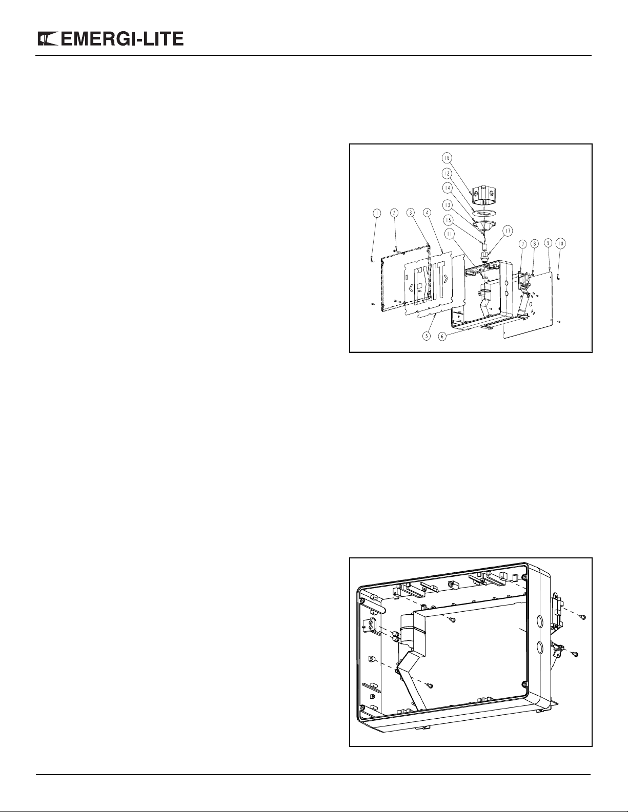
c. Remove lens, exit panel and diffuser panel on the front of the unit
(use the supplied bit to remove the tamper-proof screws).
d. In order to access the knockouts of the frame, remove the 4 elec-
tronic module screw(s) holding the electronic module to the frame
and separate them (see fig.2).
e. Remove knockout on top of the frame. Determine which holes in
the exit frame will be used for mounting (see fig.1). Support frame
by two blocks of wood, maximum one inch apart. Strike knockouts
with a hammer and screwdriver. Clear holes of burrs to allow
proper assembly of nipple/wire assembly.
f. Secure j-box cover to the frame using the provided nut.
g. Reassemble the electronic module inside the frame.
16
12
14
34
2
1
13
15
11
5
6
Figure 1
Part List
1. Tamper-proof screws short
(4 per lens)
2. Tamper-proof screws long
(2 per lens)
3. Lens
4. EXIT panel
5. Diffuser panel
6. Frame
7. Electronic module
8. Electronic module screws
(4)
17
9
10
8
7
9. Backplate (single face sign
10. Backplate tamper-proof
screws (4)
11. Lock-nuts (2)
12. Junction box gasket
13. Junction box screws(2)
14. J-box Cover
15. Nipple
16. Juction box
17. Hub
Figure 2
Emergi-Lite Tel: (888) 552-6467 ext. 547 or 255 Fax: (888) 867-1565 www.emergi-lite.com
06/07 750.1300 Rev. A
1/4
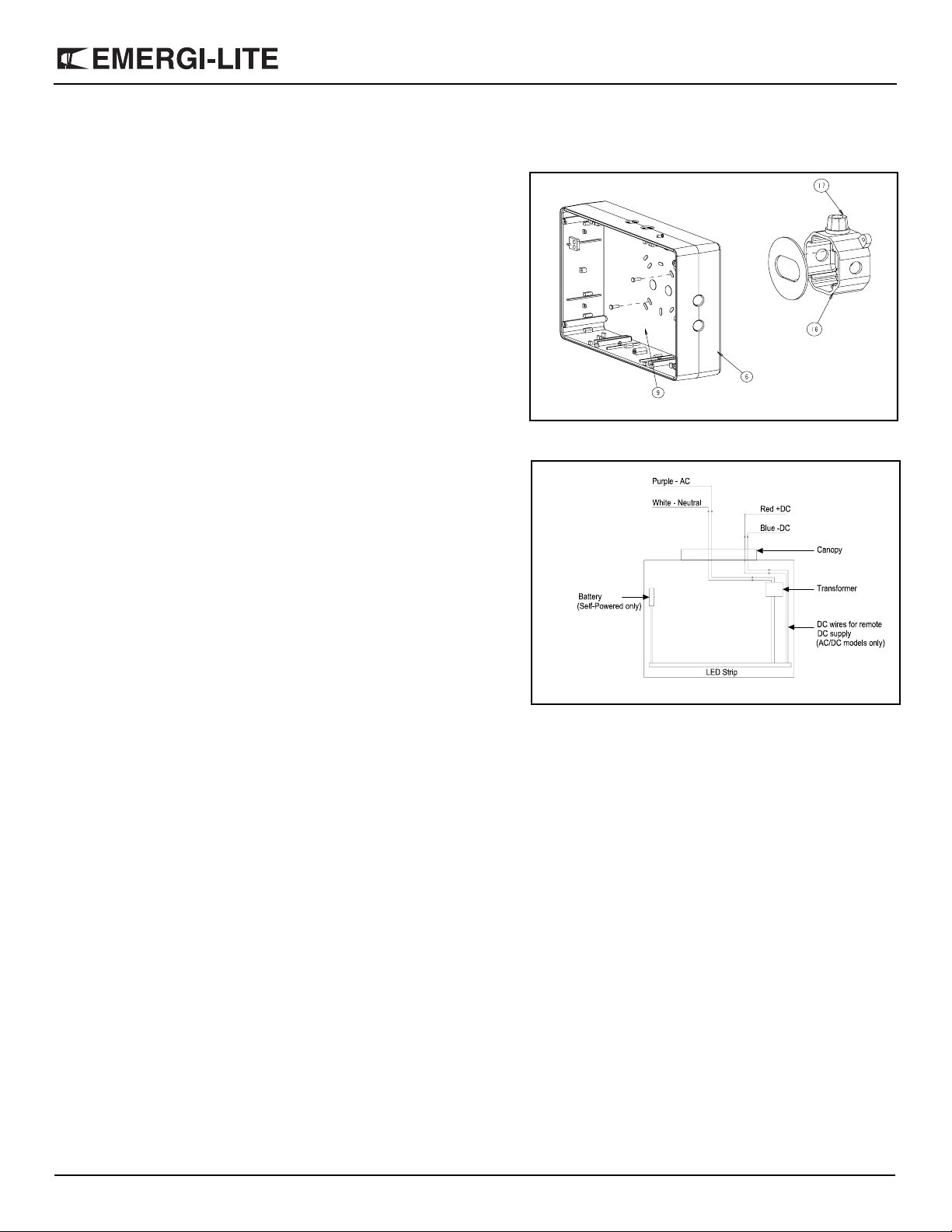
Wall Mount (Single Face Model Only)
a. Remove j-box assembly from carton. Remove j-box cover from j-
box assembly, install Hub on j-box and retain securement screw.
b. Remove the backplate(9) from the packaging. Determine the
proper knockouts to remove for mounting to the junction box (see
fig.3).
c. Support area around knockouts with two blocks of wood. Strike
knockouts from the inside with a hammer and a screwdriver.
d. Reinstall the backplate to the frame using the 6 tamper-proof
screws (use the supplied bit).
SVXHZ Series – Exit Sign
17
16
2. Electrical connections: Connect one end to the transformer leads,
inside the enclosure, and the other end, to AC line voltage inside the
junction box. Connect the white lead to neutral and the purple lead to
AC line voltage (the input is universal 110 to 347 VAC). (See fig. 4).
Connect the ground(green wire) to the junction box.
Optional: For AC models used with DC remote power. One end connects to the LED-STRIP leads, inside the enclosure, and the other
end to DC input inside the junction box. Connect the red lead to positive, and the blue lead to the negative of the remote DC input (See
fig. 4).
3. For ceiling mount: Mount the frame and j-box cover assembly to
junction box by using the provided securement screw.
For wall mount: Attach the frame(6) to the junction box, using the
junction box supplied screws.Install 2 stem washers to ensure bonding.
4. Reinstall the diffuser and the EXIT panel (if required, remove the
appropriate chevron).
5. Install the lens by using the 6 tamper-proof screws.
The tamper-proof screws should be equall y torq ue d to ap proximately 5 lbs-in (0.6 N-m).
6. Energize AC. Sign will illuminate.
Manual Testing (Self-Powered Models)
Operate the magnetic “test switch” by holding the provided magnet
underneath the unit where indicated on the frame. The AC pilot lamp will
go out, the legend will flicker, but remain lit. Remove the magnet. The
AC pilot light will turn on, the legend will flicker but remain lit.
6
9
Figure 3
Figure 4
Automatic Testing (Self-Powered Models)
The unit will perform an automatic self-test of 30 seconds every 30 days,
60 second every 60 days and a 90 minute self-test once a year.
Emergi-Lite Tel: (888) 552-6467 ext. 547 or 255 Fax: (888) 867-1565 www.emergi-lite.com
06/07 750.1300 Rev. A
2/4
 Loading...