

Emergi-Lite HZM User Manual
HZM Series
This equipment is rated for Class 1, Division 2, Groups A, B, C and D
IMPORTANT SAFEGUARDS
When using electrical equipment, basic safety precautions should
always be followed including the following:
READ AND FOLLOW ALL SAFETY
INSTRUCTIONS
1. Do not let power supply cords touch hot surfaces.
2. Do not mount near gas or electric heaters.
3. Use caution when handling batteries. Avoid possible shorting.
4. Equipment should be mounted in locations and at heights where it
will not readily be subjected to tampering by unauthorized personnel.
5. The use of accessory equipment not recommended by the manufacturer may cause an unsafe condition.
6. Caution: If optional Halogen cycle lamp(s), symbol (H—), are used in
this equipment, to avoid shattering: do not operate lamp in excess of
rated voltage, protect lamp against abrasion and scratches and
against liquids when lamp is operating, dispose of lamp with care.
7. Halogen cycle lamps operate at high temperatures. Do not store or
place flammable materials near lamp.
8. Do not use this equipment for other than intended use.
9. All servicing should be performed by qualified service personnel.
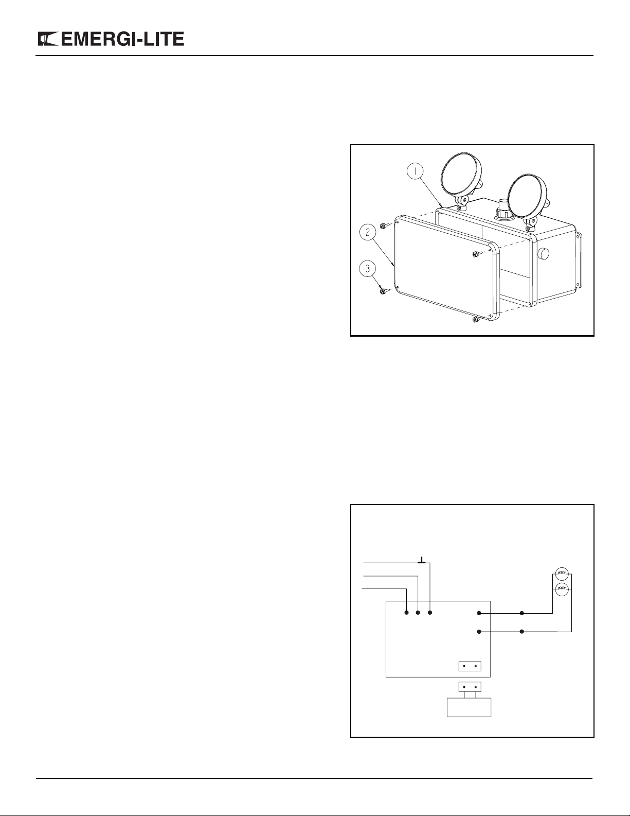
Figure 1
Part List
1. Housing
2. Door
3. Screw (4)
HZM Series
SAVE THESE INSTRUCTIONS
Installation Instructions
1. The unit is to be installed with wiring methods in accordance with the
requirements of NEC Article, 500 and 501.
2. Turn off AC power.
3. Route AC circuit wires to electrical box and leave 12” of wire length.
4. Remove four screw on door. Open door by lifting it away from housing.
5. Securely mount unit in place. Connect AC supply wiring to unit as follows (see fig. 2):
For 120 VAC operation — Black to 120 VAC, white to neutral. Insulate unused wire.
For 277 VAC operation — Orange to 277 VAC, white to neutral.
Insulate unused wire.
6. Extend DC wiring for remote fixtures (if required) to unit. Wiring must
comply with NEC articles 700, 720 and 501-4. Do not exceed rated
wattage of unit, integral and remote lampheads combined.
7. Connect two white lamp wires to black wires from circuit board with
wirenuts provided (see fig. 2). Note: lamp wires are not polarized.
AC Input
White
120 Black
277 Orange
Figure 2
Tes t
switch
+ –
Battery
Black
Black
To DC lamps
White
White
Emergi-Lite Tel: (888) 552-6467 ext. 547 or 255 Fax: (888) 867-1565 www.emergi-lite.com
03/11 750.0299 Rev. C
1/2
8. When ready to energize AC, connect batteries by plugging the red
leads into the positive terminals and the blue leads into the negative
terminals. Lamps will not light at this time.
9. Energize AC. Allow unit to charge for 24 hours before initial testing.
Heater and thermostat control (option)
This option is used in areas where temperature may drop below 0°C.
The thermostat will activate the heating pad at 0°C and will cut at 16°C.
The heating pad is rated at 50 watts. Contact factory for temperature limitations.
Testi ng
To test: depress test switch, DC lamps will illuminate. Release switch and
DC lamps will extinguish.
Maintenance
None required. Unit should be tested in accordance with local codes and
Life Safety Code, NFPA101. This equipment is furnished with a low battery disconnect circuit in the emergency mode. However, if the AC supply
to the unit is to be disconnected for 2 months or more, the battery must
be disconnected. Do not allow battery wires to short circuit.
Diagnostics
HZM Series
Pilot Light
Test
STATUS
Normal Off Off On
Battery Disconnect On Off Flash
* Battery Failure On Off Flash
Load Disconnect Off On Flash
Overload Off On Flash
*Note 1 — Battery failure when the battery voltage is below 80% of nominal 6V or 12V.
Note 2 — This feature is not a complete self-test / self diagnostic circuit
as described by UL924.
BATTERY
FAULT
LOAD
FAULT
PILOT
LIGHT
Batt <Fault> Load
Emergi-Lite Tel: (888) 552-6467 ext. 547 or 255 Fax: (888) 867-1565 www.emergi-lite.com
03/11 750.0299 Rev. C
2/2
 Loading...