

Page 1

H
TEL 888 935 3605:( ) -
FAX 888 867 1565:( ) -
FPDL-32
EMERGILITE BRAND
INSTRUCTION MANUAL
IMPORTANT SAFEGUARDS
When using electrical equipment, basic safety precautions should always be followed, including the following:
READ AND FOLLOW ALL SAFETY INSTRUCTIONS
1. - To prevent electrical shock, do not mate unit connector until installation is complete andCAUTION
power is supplied to the unit.A.C.
2. - This fixture provides more than one power supply output source. To reduce the risk of
CAUTION
electrical shock, disconnect both normal and emergency sources by turning off the A.C. Branch circuit
and by disconnecting the unit connector.
3. The battery is sealed, non-maintenance, and is not replaceable in the field. Please contact manufacturer for information on service. Do not attempt to service the battery please.
4. . The product is for use with grounded, UL Listed, indoor fixtures except in
DO NOT USE OUTDOORS
heated air outlets or hazardous locations.
5. The product requires an unswitched A.C. Power source of either 120 or 277 volts. Properly cap the
unused A.C. Lead.
6. Do not mount near gas or electric heaters.
7. The product should be mounted in locations and at heights where it will not readily be subjected to tampering by unauthorized personnel.
8. The product will cold strike and operate one 2 through 4 (20-40W) instant start, rapid start, U shape
or circline, T8 through T12 fluorescent lamps, T5 28W fluorescent lamps, including energy saving and
long compacts for 90 minutes at reduced light output.
9. The product is compatible with all A.C. magnetic and electronic ballasts including multiple lamp ballasts
with one lamp operating in the emergency mode.
10. The use of accessory equipment not recommended by the manufacturer may cause an unsafe condition.
11. Do not use this equipment for other than intended use.
12. Install in accordance with the National Electrical Code and local regulations.
13. Installation and servicing should be performed by qualified personnel.
14. Lighting fixture manufacturers, electricians and end users need to ensure product system compatibility
before final installation.
15. The battery is sealed,non-maintenance,and is not replaceable in the field. Please contact
manufacturer for information on service. Do not attempt to service the battery please.
16. The rated operating time in the emergency mode with battery is 1-1/2 hours and the recharge
time shall not be less than 24 hours.
′′
SAVE THESE INSTRUCTIONS
CONTAINS NICKEL-CADMIUM
BATTERY.MUST BE RECYCLED
OR DISPOSED OF PROPERLY.
Page 1
Ni - Cd
Page 2
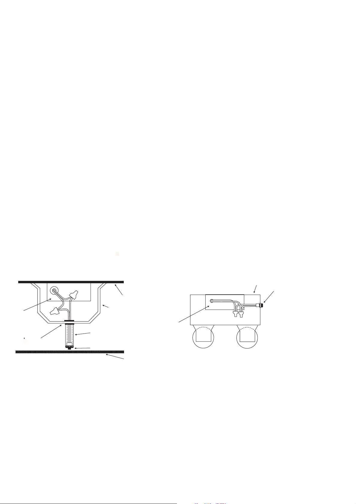
INSTALLATION INSTRUCTIONS
CAUTION: Before installing, make certain the A.C. Power is off and the battery
connector is disconnected.
1. MOUNTING THE FPDL-32
1
Remove the ballast channel cover. Mount the FPDL-32 in the ballast channel at least away from the A.C. Ballast(s).
1
2
When battery packs are remote mounted, the remote distance can not exceed of the distance from ballast to
lamp specified by the A.C. Ballast manufacturer. For example, if the A.C. Ballast manufacturer recommends no
more than 25¡remote distance, then the battery pack should not exceed 12 . Under no circumstances should
/
1
¡
/
2
2"
/
the battery pack exceed a distance of 50¡from the lamp.
2. WIRING
Refer to the wiring diagrams on the back page for the appropriate wiring of lamp(s) and ballast. Install in accordance
with the National Electrical Code and local regulations. For additional wiring diagrams consult Customer Service.
3. INSTALLING THE LIGHTED
Recessed Troffer Fixture
7
punch a / hole ( / knockout). Insert the / bushing into the hole. Push the plastic tube through the bushing.
8"
1
2"
Route the leads of the through the plastic tube. Connect the LED wires from the unit to the
iolet Brown
(V to Red, to White/Red). Push the entire assembly back into the tube until the lens collar rests against the plastic
tube. The plastic tube should be adjusted so that the is within / of the fixture lens. The
must be visible after installation. Refer to
Strip Fixture -
Select a convenient location on the fixture so the can be seen after installation.
Allow for proper clearance inside the fixture and drill or punch a1/2" hole. Remove the nut from the
. Push the housing into the1/2" hole and secure with the nut. Connect the LED wires
from the .
TBTS
TBTS
(Violet to Red, Brown to White/Red)
- Select a convenient location with proper clearance in the ballast cover and drill or
7
8"
INDICATOR LIGHT INDICATOR LIGHT
1
INDICATOR LIGHT INDICATOR LIGHT
4"
Illustration 1.
TBTS
TBTS
Refer to Illustration 2.
Illustration 1
Recessed Troffer Fixture
FPDL-32
PLASTIC TUBE
7/8 BUSHING
TBTS
4. WIRING THE A.C. INPUT
A. The and A.C. Ballast be on the same branch circuit.FPDL-32 must
B. The requires an A.C. Power source of either 120 or 277 volts. Select the proper voltage lead
and cap the unused lead.
C. When the is used with a switched fixture, theA.C. Input to the must be connected ahead of the
FPDL-32 FPDL-32
fixture switch. Refer to for switched and unswitched fixture wiring diagrams.
unswitchedFPDL-32
Illustration 3
FIXTURE
BALLAST CHANNEL COVER
FIXTURE LENS
Illustration 2
Strip Fixture
FIXTURE
TBTS
FPDL-32
OBSERVE PROPER POLARITY
Page 2
Page 3
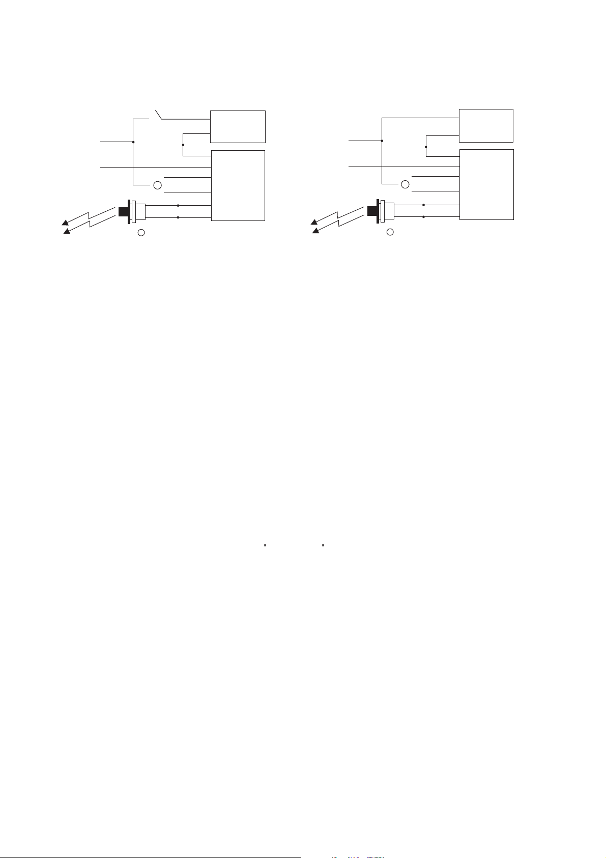
5. BALLAST WIRING BLOCK DIAGRAM
Illustration 3
HOT A.C. LINE
COMMON
TBTS
Switched Fixture
BLACK
A.C. BALLAST
WHITE
WHT/BLK
WHITE
(277V) ORG
1
(120V) BLK
WHT
+RED
1
Select proper voltage lead. Cap unused lead.
WHT/RED
FPDL-32
+RED
HOT A.C. LINE
COMMON
TBTS
Unswitched Fixture
BLACK
WHITE
WHT/BLK
WHITE
(277V) ORG
1
(120V) BLK
WHT
+RED
1
Select proper voltage lead. Cap unused lead.
WHT/RED
+RED
6. LABELS
Attach the appropriate labels adjacent to the .Annotate Re-lamping label for lamp type and wattage. The
Caution and the Re-lamping labels must be on the fixture in a readily visible location to anyone attempting to
service the fixture.
TBTS
7. COMPLETING INSTALLATION
When the installation is complete, switch the A.C. power on and join the unit connector.
FPDL-32
OPERATION
A.C. BALLAST
FPDL-32
Normal Mode - A.C. power is present. TheA.C. ballast operates the fluorescent lamp(s) as intended. The is in the
standby charging mode. The will be lit providing a visual indication that the battery is being charged.
Emergency Mode - The A.C. Power fails. The senses the A.C. Power failure and automatically switches to the
Emergency Mode
restored, the switches the system back to the and resumes battery charging. See page 1 of the
. One lamp is illuminated, at reduced output, for a minimum of 90 minutes. When the A.C. Power is
FPDL-32
TBTS
FPDL-32
Normal Mode
FPDL-32
Instruction Manual.
TESTING & MAINTENANCE
Pressing the red lens on the turns off the light on the and forces the unit into emergency
mode. This interrupts power to the emergency lamps only. The emergency lamp is now being lit by the unit and will be less
bright than the other lamps in the system. To simulate a BLACK OUT use the or circuit breaker to turn off A.C. Power.
Initial Testing - Allow the unit to charge approximately 1 hour, then press the to conduct a short discharge test.
Allow a 24 hour charge before conducting 90 minute test.
FPDL-32
The is a maintenance free unit, however, periodic inspection and testing is required. NFPA 101, Life Safety Code,
outlines the following schedule:
Monthly - Insure that the is illuminated. Conduct a 30 second discharge test by depressing the
. One lamp should operate at reduced output.
Annually - Insure that the is illuminated. Conduct a full 11/2 hour discharge test. The unit should operate as
intended for the duration of the test.
"Written records of testing shall be kept by the owner for inspection by the authority having jurisdiction."
TBTS TBTS
FPDL-32
TBTS
TBTS TBTS
TBTS
SERVICING SHOULD BE PERFORMED BY QUALIFIED PERSONNEL.
Page 3
Page 4
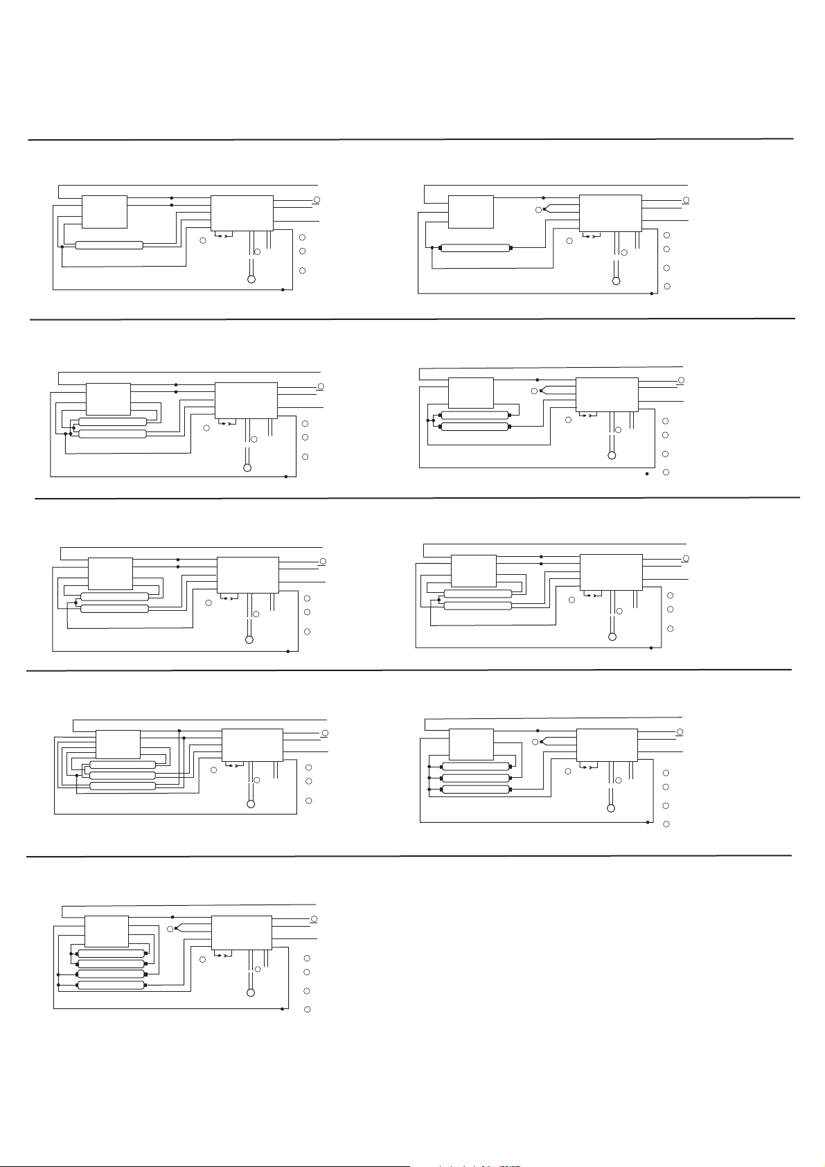
TYPICAL WIRING DIAGRAMS
Typical schematics only may be used other ballast, consult the factory wiring diagram
1. ONE LAMP RAPID START BALLAST
SWITCHED OR
UNSWITCHED
BLACK
WHITE
RED
RED
A.C.
Ballast
*LAMP
*AC/EMERGENCY
BLUE
BLUE
BLUE
BLUE/WHT
YELL/BLK
YELLOW
RED
CONNECTOR
COMMON
2
UNIT
FPDL-32
WHT/RED
3
WHT
RED
RED
TBTS
ORG (277V)
BLK (120V)
WHITE
WHT/BLK
VIOLET
VIOLET
LINE
1
UNSWITCHED
COMMON
1
SELECT PROPER VOLTAGE
LEAD CAP UNUSED LEAD.
2
DO NOT MATECONNECTOR UNTIL
INSTALLATIONIS COMPLETE AND
AC POWER IS SUPPLIED.
3
TESTACCESSORY LEADSREFER TO INSTALLATION
INSTRUCTIONS FOR PROPER
POLARITY WIRING.
3. TWO LAMP RAPID START BALLAST
SWITCHED OR
UNSWITCHED
BLACK
WHITE
YELLOW
YELLOW
A.C.
Ballast
LAMP
*LAMP
*AC/EMERGENCY
BLUE
BLUE
RED
RED
BLUE
BLUE/WHT
YELL/BLK
YELLOW
RED
CONNECTOR
COMMON
2
UNIT
FPDL-32
RED
WHT/RED
3
RED
WHT
TBTS
VIOLET
VIOLET
ORG (277V)
BLK (120V)
WHITE
WHT/BLK
5. TWO LAMP T-5 SERIES YELLOW FILAMENT
BLACK
WHITE
YELLOW
YELLOW
A.C.
Ballast
LAMP
*LAMP
*AC/EMERGENCY
BLUE
BLUE
RED
RED
BLUE
BLUE/WHT
YELL/BLK
YELLOW
RED
CONNECTOR
COMMON
2
UNIT
FPDL-32
RED
WHT/RED
3
RED
WHT
TBTS
VIOLET
VIOLET
ORG (277V)
BLK (120V)
WHITE
WHT/BLK
LINE
1
UNSWITCHED
COMMON
1
SELECT PROPER VOLTAGE
LEAD CAP UNUSED LEAD.
2
DO NOT MATECONNECTOR UNTIL
INSTALLATIONIS COMPLETE AND
AC POWER IS SUPPLIED.
3
TESTACCESSORY LEADSREFER TO INSTALLATION
INSTRUCTIONS FOR PROPER
POLARITY WIRING.
SWITCHED OR
UNSWITCHED
LINE
1
UNSWITCHED
COMMON
1
SELECT PROPER VOLTAGE
LEAD CAP UNUSED LEAD.
2
DO NOT MATECONNECTOR UNTIL
INSTALLATIONIS COMPLETE AND
AC POWER IS SUPPLIED.
3
TESTACCESSORY LEADSREFER TO INSTALLATION
INSTRUCTIONS FOR PROPER
POLARITY WIRING.
2. ONE LAMP INSTANT START BALLAST
SWITCHED OR
UNSWITCHED
BLACK
WHITE
RED
A.C.
Ballast
*LAMP
*AC/EMERGENCY
BLUE BLUE
3
BLUE/WHT
YELL/BLK
YELLOW
RED
CONNECTOR
COMMON
2
UNIT
FPDL-32
RED
WHT/RED
4
RED
WHT
ORG (277V)
BLK (120V)
WHITE
WHT/BLK
VIOLET
VIOLET
LINE
1
UNSWITCHED
COMMON
1
SELECT PROPER VOLTAGE
LEAD CAP UNUSED LEAD.
2
DO NOT MATECONNECTOR UNTIL
INSTALLATIONIS COMPLETE AND
AC POWER IS SUPPLIED.
3
CONNECT BLU/WHTAND YELL/BLK
WIRES TOGETHER.
TESTACCESSORY LEADS-
4
REFER TO INSTALLATION
INSTRUCTIONS FOR PROPER
POLARITY WIRING.
4. TWO LAMP INSTANT START BALLAST
SWITCHED OR
UNSWITCHED
LINE
1
UNSWITCHED
COMMON
1
SELECT PROPER VOLTAGE
LEAD CAP UNUSED LEAD.
2
DO NOT MATECONNECTOR UNTIL
INSTALLATIONIS COMPLETE AND
AC POWER IS SUPPLIED.
3
CONNECT BLU/WHTAND YELL/BLK
WIRES TOGETHER.
TESTACCESSORY LEADS-
4
REFER TO INSTALLATION
INSTRUCTIONS FOR PROPER
POLARITY WIRING.
SWITCHED OR
UNSWITCHED
ORG (277V)
BLK (120V)
WHITE
WHT/BLK
LINE
1
UNSWITCHED
COMMON
1
SELECT PROPER VOLTAGE
LEAD CAP UNUSED LEAD.
2
DO NOT MATECONNECTOR UNTIL
INSTALLATIONIS COMPLETE AND
AC POWER IS SUPPLIED.
3
TESTACCESSORY LEADSREFER TO INSTALLATION
INSTRUCTIONS FOR PROPER
POLARITY WIRING.
BLACK
WHITE
RED
A.C.
Ballast
LAMP
*LAMP
*AC/EMERGENCY
BLUE
BLUE
3
BLUE
BLUE/WHT
YELL/BLK
YELLOW
RED
CONNECTOR
COMMON
2
UNIT
FPDL-32
RED
WHT/RED
4
RED
WHT
TBTS
VIOLET
ORG (277V)
BLK (120V)
WHITE
WHT/BLK
VIOLET
6.TWO LAMP OSRAM SYLVANIA ONLY PROGRAM
RAPIDSTART
BLACK
WHITE
YELLOW
YELLOW
A.C.
Ballast
LAMP
*LAMP
*AC/EMERGENCY
RED
RED
BLUE
BLUE
BLUE
BLUE/WHT
YELL/BLK
YELLOW
RED
CONNECTOR
COMMON
2
UNIT
FPDL-32
RED
WHT/RED
3
RED
WHT
TBTS
VIOLET
VIOLET
7. THREE LAMP RAPID START BALLAST
SWITCHED OR
UNSWITCHED
BLACK
WHITE
BLUE
BLUE
YELLOW
YELLOW
A.C.
Ballast
LAMP
*LAMP
LAMP
*AC/EMERGENCY
BLUE/WHT
BLUE/WHT
RED
RED
BLUE
BLUE/WHT
YELL/BLK
YELLOW
RED
CONNECTOR
COMMON
2
UNIT
FPDL-32
RED
WHT/RED
3
RED
WHT
TBTS
VIOLET
ORG (277V)
BLK (120V)
WHITE
WHT/BLK
VIOLET
LINE
1
UNSWITCHED
COMMON
1
SELECT PROPER VOLTAGE
LEAD CAP UNUSED LEAD.
2
DO NOT MATECONNECTOR UNTIL
INSTALLATIONIS COMPLETE AND
AC POWER IS SUPPLIED.
3
TESTACCESSORY LEADSREFER TO INSTALLATION
INSTRUCTIONS FOR PROPER
POLARITY WIRING.
9. FOUR LAMP INSTANT START BALLAST
SWITCHED OR
UNSWITCHED
BLACK
WHITE
YELLOW
YELLOW
A.C.
Ballast
LAMP
LAMP
LAMP
*LAMP
*AC/EMERGENCY
BLUE
BLUE
RED
RED
3
BLUE
BLUE/WHT
YELL/BLK
YELLOW
RED
CONNECTOR
COMMON
2
UNIT
FPDL-32
WHT/RED
WHT
RED
4
RED
TBTS
VIOLET
VIOLET
ORG (277V)
BLK (120V)
WHITE
WHT/BLK
LINE
1
UNSWITCHED
COMMON
1
SELECT PROPER VOLTAGE
LEAD CAP UNUSED LEAD.
2
DO NOT MATECONNECTOR UNTIL
INSTALLATIONIS COMPLETE AND
AC POWER IS SUPPLIED.
3
CONNECT BLU/WHTAND YELL/BLK
WIRES TOGETHER.
TESTACCESSORY LEADS-
4
REFER TO INSTALLATION
INSTRUCTIONS FOR PROPER
POLARITY WIRING.
NOTE: Use the proper input voltage lead, cap unused lead
8. THREE LAMP INSTANT START BALLAST
SWITCHED OR
UNSWITCHED
BLACK
WHITE
RED
A.C.
Ballast
LAMP
LAMP
*LAMP
*AC/EMERGENCY
BLUE
BLUE
BLUE
3
BLUE
BLUE/WHT
YELL/BLK
YELLOW
RED
CONNECTOR
COMMON
2
UNIT
FPDL-32
RED
WHT/RED
4
RED
WHT
TBTS
VIOLET
ORG (277V)
BLK (120V)
WHITE
WHT/BLK
VIOLET
LINE
1
UNSWITCHED
COMMON
1
SELECT PROPER VOLTAGE
LEAD CAP UNUSED LEAD.
2
DO NOT MATECONNECTOR UNTIL
INSTALLATIONIS COMPLETE AND
AC POWER IS SUPPLIED.
3
CONNECT BLU/WHTAND YELL/BLK
WIRES TOGETHER.
TESTACCESSORY LEADS-
4
REFER TO INSTALLATION
INSTRUCTIONS FOR PROPER
POLARITY WIRING.
Page 4
Page 5

LAMP SELECTOR LEAD INSTRUCTIONS
This unit features Lamp Selector Leads (violet) for optimizing light
output of specified lamps. The unit is shipped from the factory with the
6 leads disconnected and capped.£
SWITCHED OR
UNSWITCHED
LINE
1
UNSWITCHED
COMMON
SELECT PROPER VOLTAGE
LEAD CAP UNUSED LEAD.
DO NOT MATE CONNECTOR UNTIL
INSTALLATION IS COMPLETE AND
AC POWER IS SUPPLIED.
LAMP SELECTOR LEADS-REFER
TO INSTALLATION INSTRUCTIONS,
LAMP OPERATION SECTION FOR
VARIOUS OPTIONS.
CONNECT BLU/WHT AND YELL/BLK
WIRES TOGETHER.
BLACK
WHITE
A.C.
Ballast
LAMP
*LAMP
*AC/EMERGENCY
BLUE
RED
4
BLUE
BLUE/WHT
YELL/BLK
RED
YELLOW
2
CONNECTOR
COMMON
EMERGENCY
BALLAST
UNIT
WHT/RED
TBTS /
CHARGE INDICATOR
RED (+)
VIOLET
ORG (277V)
BLK (120V)
WHITE
WHT/BLK
1
VIOLET
3
2
3
4
This unit can be used with most 2'-4' lamps. Refer to the chart below for the type of
lamp(s) operated and the number of lamps to be operated in emergency mode.
OPTION
1
2
LAMP TYPE
2FTT8-T12
Single, Bipin(up to 20W)
4FT T8-T12
Single, Bipin( 20~40W)
For T5 Lamp MAX,28W
EMERGENCY
OPERATION
One Lamp
One Lamp
*VIOLET LEADS
Connected
Disconnected
WIRING
DIAGRAMS
1,2,3,4,5,6,7,8,9
1,2,3,4,5,6,7,8,9
FPDL-32 Insert
A-0 Rev 0910
Page 5
 Loading...