

Page 1
Electric Installation.
Installation and user instructions for
Eye and Media cable managed desks
BS6396: 2008 Electrical Systems in Office
Furniture & Educational Furniture
Electrical equipment and installations must be designed and
tested to ensure their safety and to comply with statutory
regulations, in particular the “Electricity at Work Regulations”.
Relevant British Standards may be used as a means of
demonstrating safety and compliance with the regulations.
In the case of electrical systems in office furniture and educational
furniture, the relevant standard for systems connected to the
mains supply by means of a 13A plug is BS 6396:2008.
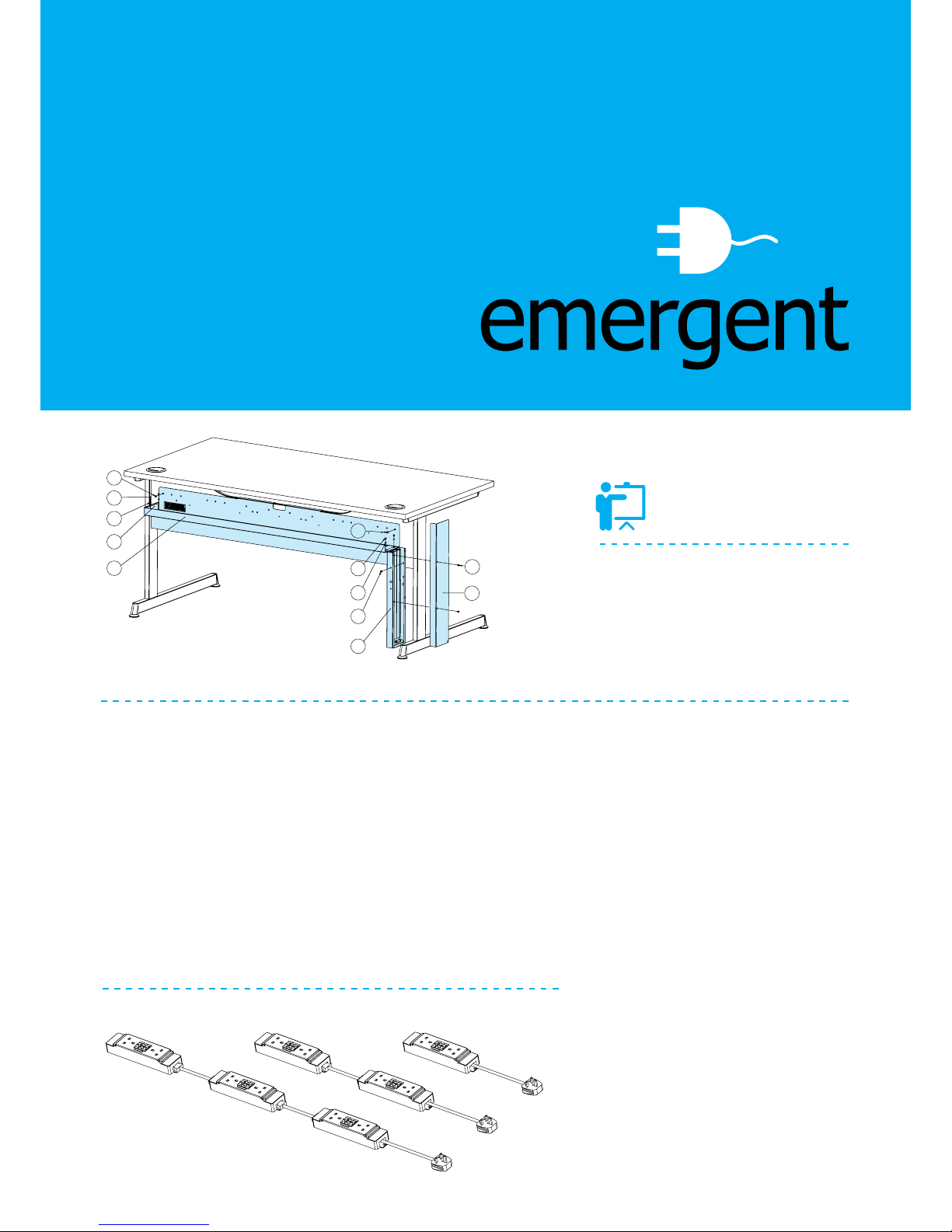
A. Media/Eye Trunking
B. No. 8 x ½” Woodscrew
C. Trunking End Cap
D. M4 Taptite Screw
E. Serrated Washer
F. Media Leg Riser
G. Leg Riser Cover
Sockets installed in office furniture are
intended to supply office equipment with
a rating not exceeding 5A with BS 6396
referring to all office furniture electrical
installations when completed must be tested.
Section 7 of BS 6396 sets out the procedures.
These tests should also be carried out on
reconfigured desks and screens as well
as new installations. Periodic inspections
and tests must be carried out to fulfil the
requirements of BS 6396 and the “Electricity
at Work Regulations” in maintaining a safe
working environment.
Sockets installed in office furniture are
intended to supply office equipment with
a rating not exceeding 5A.
The diagrams on the left indicate the
maximum number of socket outlets that may
be connected from a single power supply
cable fed from a 13 Amp BS 1363 plug and
their relevant fuse ratings.
DIAGRAM B
20mm Ceramic Fuses
DIAGRAM A
Electrical items required
B
D
E
C
A
B
D
E
B
F
D
G
6 Outlets 4 Outlets 2 Outlets
5A Fuse
5A Fuse
3.15A Fuse
3.15A Fuse
3.15A Fuse
13A Plug Fuse
Unfused
Page 2
It is important to bear in mind that there
is always some risk involved in handling
electrical equipment so all reasonable
care must be taken in following these
instructions to minimise the risk.
We recommend that a suitable qualified
electrical engineer is used to install and
test the power accessories and earthing
provision. The cable management is of
earthed construction. Maximum load 50Hz
13 amp. Maximum load per socket 5 amp.
For safety and compliance with
BS.6396:2008 the following socket
configurations and numbers must not be
exceeded. (30Ma R.C.D 13 AMP mains
plug optional) SEE DIAGRAM B.
On completion or re-configuration of
the electrical system within the furniture
the following electrical tests must be
carried out. It is recommended that these
tests are repeated at least annually for
continued safety.
Continuity & Polarity.
A test of all conductors, including the
protective earth conductor, Shall be made
to verify their continuity and correct polarity.
This test shall include the supply cord
and plug. The electrical system shall be
inspected to ensure that any fuses and any
single pole switches fitted are connected
only in the live conductor.
Insulation Resistance.
The insulation resistance of completed
electrical installations shall be tested using
a 500V D.C. test supply. The measured
resistance shall be not less than 1 M ohm.
Tests shall be made between conductors
and also to earth of the supply cable. The
duration of each test shall be not less than
5 seconds.
Note – Neon indicators shall be removed
from the circuit before carrying out this test
between conductors by switching off the
socket outlet. Where luminaries contain
sensitive electronic components, these
shall be disconnected prior to the test (see
713-04-04 of BS 7671)
Earth Continuity.
Earth connections of the installed socket
outlets and the accessible metal parts of
the earthed office furniture shall be tested
by passing a current of not less than 1.5
times the rating of the supply plug fuse
and no greater than 25 A, derived from
an a.c source with a load voltage not
exceeding 12 V. The tests shall include
the supply cord and shall be carried out
between the earth pin of the supply plug,
the earth connections of the installed
socket outlets and where applicable the
accessible metal parts of the earthed
furniture. The duration of the tests shall be
for a period 5 s and 20 s. The resistance
shall not exceed 0.1 Ohm.
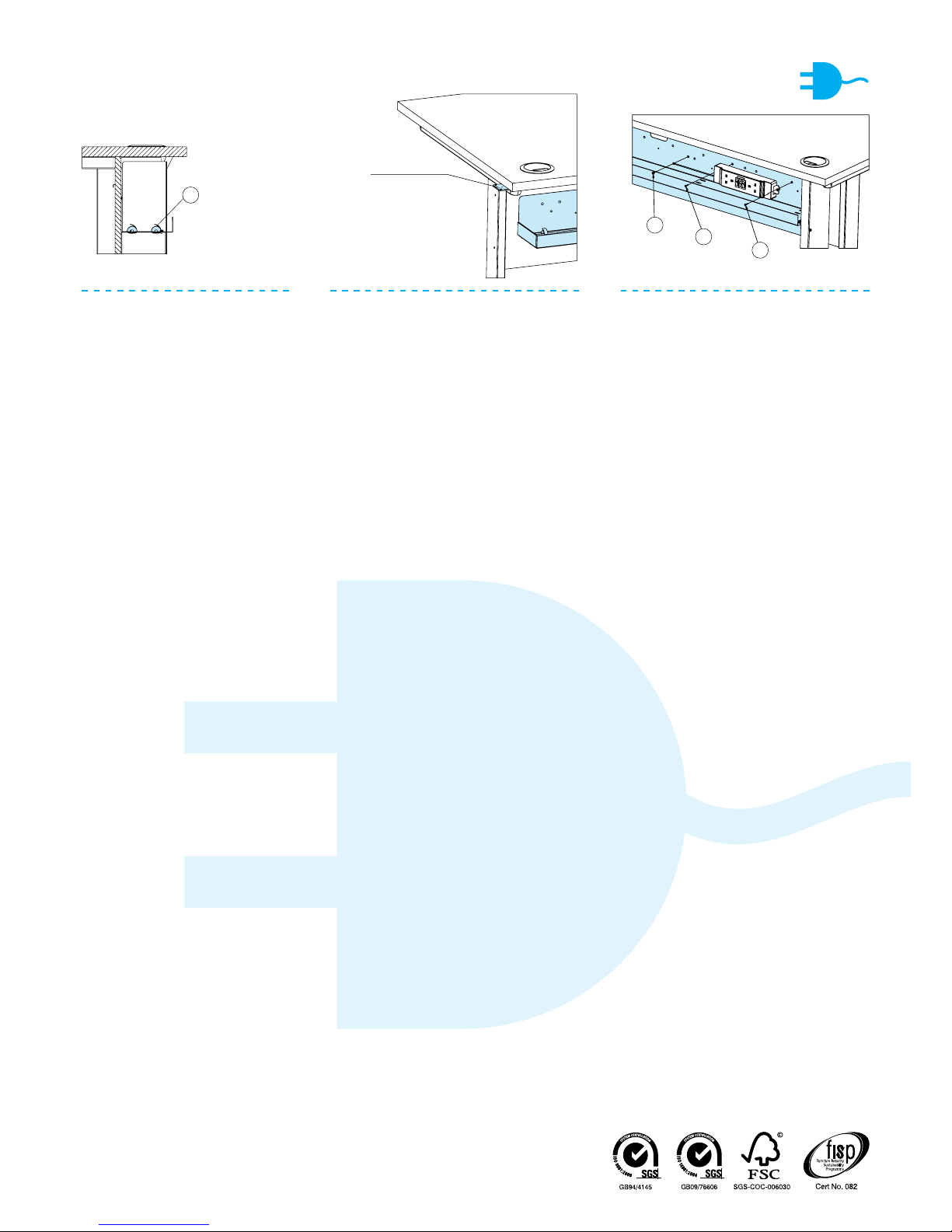
Trunking Assembly
To Desking
SEE DIAGRAM A. Hang the trunking
(A) over the modesty panel. Fasten to
the modesty panel with 2 off No. 8 x ½”
woodscrews (B). Fasten the trunking end
cap (C) to the end of the trunking with 2 off
M4 taptite screws and serrated washers (D
& E). Fasten the leg riser (F) to the trunking
with 2 off M4 taptite screws and serrated
washers (D & E). Fasten the leg riser to
the modesty panel with 1 off No. 8 x ½”
woodscrew (B). Fasten the leg riser cover
(G) to the leg riser with 2 off M4 taptite
screws (D).
Cable Routes.
Where desks are linked together the best
position for cables to enter is either at
the beginning or end of a configuration.
Cables will normally enter desks at the
bottom of the leg riser and be anchored
by the cable clamp provided. Where
cables run from the building out to the
desks, these exposed lengths [from the
plug to the cable entry point or appliance
inlet connector] should be as short as
possible and must not exceed 2 metres.
Cables should be positioned so as not
to be a hazard to people walking by. Use
cable ties (H – SEE DIAGRAM C) in the
trunking slots to segregate power and
data cables. Run power and data cables
in separate channels in the leg riser plastic
channel. Where cables run from desk to
desk, these desks must be securely linked
together using the plates provided.
(SEE DIAGRAM D).
Power Socket
Installation
SEE DIAGRAM E. First decide on the
position of the socket inside the horizontal
face of the trunking, then fasten through
the socket lugs through clearance holes in
trunking into the modesty panel with 2 off
No. 6 x ½” csk woodscrews (J ). Connect
the socket earth lead to a nearby marked
earth point with 1 off No. 8 x ½” selftapping screw (K).
DIAGRAM C
Emergent Crown Ltd, Unit 5, Browmills Industrial Estate,
Brighouse Road, Hipperholme, Halifax HX3 8EF
t.01422 349119 e.sales@emergent-crown.co.uk w.www.emergent-crown.co.uk
H. Cable Ties
K. No. 8 x ½” Self-Tapping Screw
J. No. 6 x ½” Countersunk Woodscrew
DIAGRAM D
Linking Plate
DIAGRAM E
K
J
J
H
 Loading...