

Page 1
EMCS
USER GUIDE
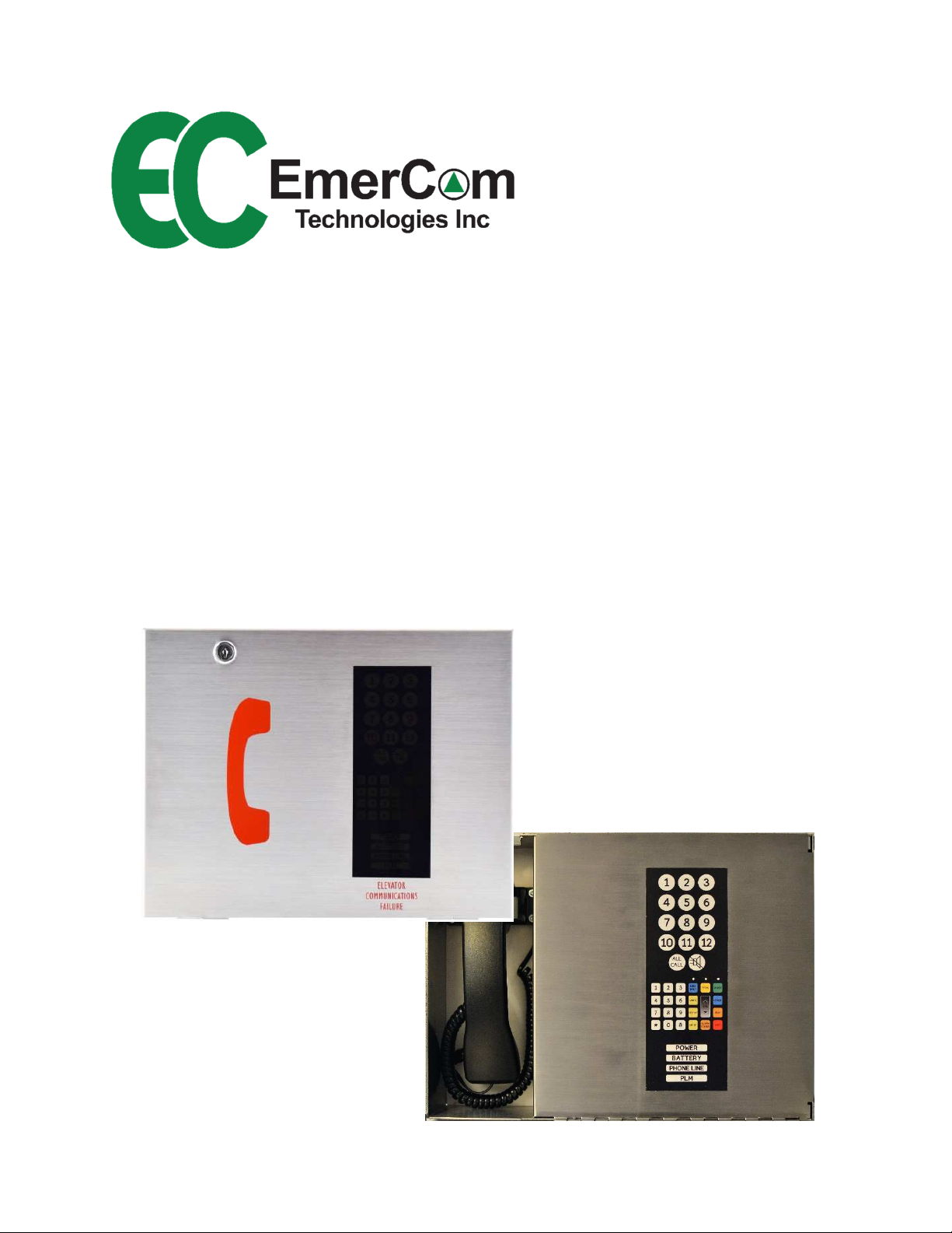
Emergency Master Control Station
Phone Consolidator
Page 2
EMCS User Guide
Other Models
EMCS-MR EMCS-OEM
- 2 -
Page 3
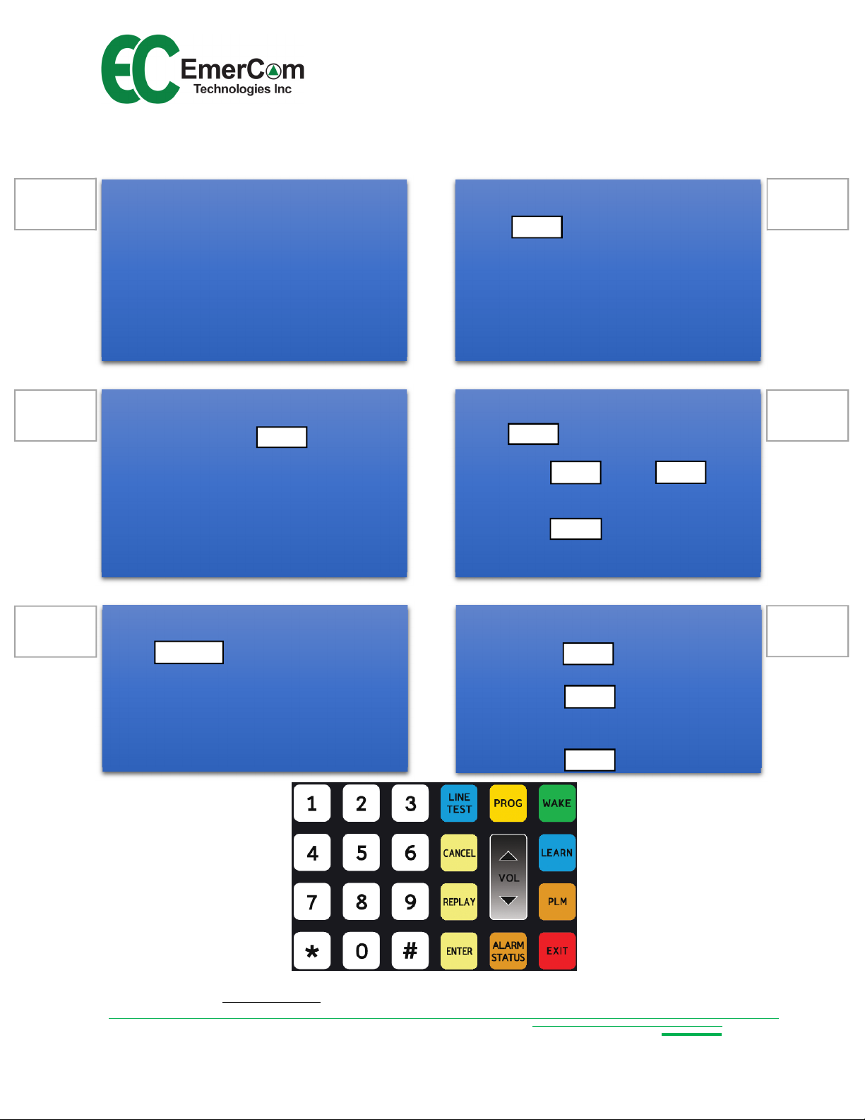
Quick Start Guide
See 6.1 for complete Cmd list
Touch
EMCS User Guide
1
2
Connect wiring:
Cab Phones
Phone lines (TEL 1 and/or 2)
Remote Phones to MR
EMC-ALRMs to lobby alarm boards
Video triggers to I/O device
Power (PWR IN)
NiMH battery (BAT)
Wake unit:
Lift handset and touch to activate
the 24 button keypad
or
Call into the EMCS-MR from a remote phone
and enter remote programming mode
(see 6.3)
WAKE
Learn Mode:
Touch . If a phone line is detected,
respond to prompt for TEL or Intelli-Split
mode. Otherwise, select LOBBY for internal
calling only. Learn Mode searches for:
Program Mode (via keypad):
Touch PROG to enter programming mode.
Change parameters by selecting:
Review parameters by selecting:
LEARN
Cab Phones (Stations)
Phone lines (TEL 1 and/or 2 or None)
PROG
<Cmd #> ENTER <value> ENTER
<Cmd #> REPLAY
ENTER
R
EPLAY
ENTER
4
5
3
Line test:
Touch . The LINE TEST LED will
turn on and the EMCS goes off-hook. Wait
for dial tone then use the keypad to dial a
test number (e.g. a cellphone). Hang-up to
disconnect from the called party ending the
call.
LINE TEST
24 button touch keypad
Customer Care: Call 1-844-EMERCOM (1-844-363-7266) for assistance.
Configure PLM Groups:
Touch
Select Group # on 24 button keypad
Touch
Icons in selected group light up
Touch icon to toggle to default Grp 1
PLM
ENTER
ENTER
6
- 3 -
Page 4

EMCS User Guide
Copyright © 2018 by EmerCom Technologies Inc
EMCS User Guide
ALL RIGHTS RESERVED
NOTICE
The information in this document has been carefully checked and is believed to be accurate. However,
no responsibility is assumed or implied for inaccuracies. Furthermore, EmerCom Technologies Inc
reserves the right to make changes to any products herein described to improve reliability, function or
design. EmerCom Technologies Inc does not assume liability arising from the application or use of any
product or circuit described herein; neither does it convey any license under its patent rights nor the
rights of others.
This manual and all data contained constitute proprietary information of EmerCom Technologies Inc and
shall not be reproduced, copied or disclosed to others, or used as the basis for manufacture without
written consent of EmerCom Technologies Inc.
Changes (1.5 to 1.6)
Cmd 24: CID Update Timer
Cmd 25: Start PLM Test
Cmd 26: PLM check interval – 0=12 hours; 1= 5hours
Cmd 60: EMCS ID (was Cmd 25)
- 4 -
Page 5

EMCS User Guide
Contents
1. About the EMCS Emergency Consolidator..................................................................................... 7
1.1 Key Features ............................................................................................................................ 7
2. Circuit Board Layout & Connections.............................................................................................. 8
3. Description of Operation: ............................................................................................................. 9
4. Diagnostics ................................................................................................................................. 10
4.1 Learn Mode............................................................................................................................ 10
4.2 Self-diagnostics ...................................................................................................................... 10
4.3 PLM (Phone Line Monitoring) ................................................................................................. 11
4.4 Phone LINE TEST .................................................................................................................... 11
5. Additional Features .................................................................................................................... 12
5.1 Overriding an emergency call ................................................................................................. 12
5.2 System-wide paging (ALL CALL) .............................................................................................. 12
5.3 Internal Calling ....................................................................................................................... 12
5.4 Non-emergency off-site calls .................................................................................................. 12
5.5 Video Triggering ..................................................................................................................... 12
6. Programming.............................................................................................................................. 13
6.1 Summary Table ...................................................................................................................... 13
6.2 Programming Details .............................................................................................................. 15
6.2.1 Command # 1: LEARN MODE .......................................................................................... 15
6.2.2 Command # 2: OPERATING MODE .................................................................................. 16
6.2.3 Command # 3: PHONE LINES AVAILABLE ......................................................................... 16
6.2.4 Command # 4: ACTIVE STATIONS .................................................................................... 16
6.2.5 Command # 5: INACTIVE STATIONS ................................................................................ 16
6.2.6 Command # 6: SERIAL NUMBER PLAYBACK ..................................................................... 16
6.2.7 Command # 7: MAIN FIRMWARE VERSION PLAYBACK .................................................... 16
6.2.8 Command # 8: ALARM STATUS PLAYBACK ...................................................................... 17
6.2.9 Command # 9: ACCESS CODE .......................................................................................... 17
6.2.10 Command # 10: LANGUAGE ............................................................................................ 17
6.2.11 Command # 14: AUTO ANSWER...................................................................................... 17
6.2.12 Command # 23: RING PHONE EXTENSION ....................................................................... 18
- 5 -
Page 6

EMCS User Guide
6.2.13 Command # 24: CALLER ID UPDATE TIMER ..................................................................... 18
6.2.14 Command # 25: START PLM TEST.................................................................................... 18
6.2.15 Command # 26: PLM CHECK INTERVAL ........................................................................... 18
6.2.16 Command # 30: HANDSET VOLUME SETTING (not EMCS-MR) ......................................... 19
6.2.17 Command # 31: HANDSET MIC. SENSITIVITY (not EMCS-MR) .......................................... 19
6.2.18 Command # 32 & # 33: PHONE LINE #1 / #2 BOOST ........................................................ 19
6.2.19 Command # 34: REMOTE PHONE ATTENUATION ............................................................ 19
6.2.20 Command # 43: FACTORY RESET ..................................................................................... 19
6.2.21 Command # 44: REMOTE SILENCE BUZZER ..................................................................... 19
6.2.22 Commands # 50 to # 56: PLM GROUP ASSIGNMENT (EMC-MR) ...................................... 20
6.2.23 Command # 60: EMCS ID ................................................................................................ 20
6.3 Remote Programming ............................................................................................................ 21
7. Precautions ................................................................................................................................ 22
8. Mechanical ................................................................................................................................. 23
8.1 Dimensions ............................................................................................................................ 23
9. Keys and Indicators..................................................................................................................... 24
9.1 Keypad ................................................................................................................................... 24
9.2 LEDs and Indicators ................................................................................................................ 25
10. Ordering ..................................................................................................................................... 25
11. Specifications ............................................................................................................................. 26
12. Warranty .................................................................................................................................... 27
13. FCC Notice and Customer Information ........................................................................................ 28
14. Industry Canada Certification ..................................................................................................... 30
- 6 -
Page 7

EMCS User Guide
1. About the EMCS Emergency Consolidator
1.1 Key Features
ASME A17.1/CSA B44 Safety Code for Elevators requires the means to call into
any elevator from within a tall building with elevator travel greater than 60’ (18m).
The EMCS Consolidator manages this operation through its handset and any
connected remote handsets, overriding off-site calls in progress.
Intuitive visual and audible indications for system operation and call routing
- Colour-coded touch-control icons indicate each elevator phone status
- Voice prompts announce current system status to any handset away from
the main display, either on-site or off-site, with on-site CID display
System-wide page (ALL CALL) from on- or off-site to all elevators
2 concurrent calls to reduce wait time in a broad emergency
Ease of setup and operation
- "Learn" mode to automatically configure the system
- Programmable Phone Line Monitoring (PLM) group configuration
- “Line Test” mode to assess the building phone line
- Remote phones can call off-site
- Bilingual voice prompts
- Touch keypad (French overlay available)
Advanced diagnostics
- Built-in Phone Line Monitoring (PLM) from each elevator to the EMCS and
for each connected TEL line as required by Code
- Watchdogs with counters for automatic fault recovery and reporting
- Remotely simulate alarm call
3 PLM group alarm relays for every 6 cabs (fail safe - closed when no alarm)
Built-in Video Trigger relay per elevator (normally open) plus all-clear signal
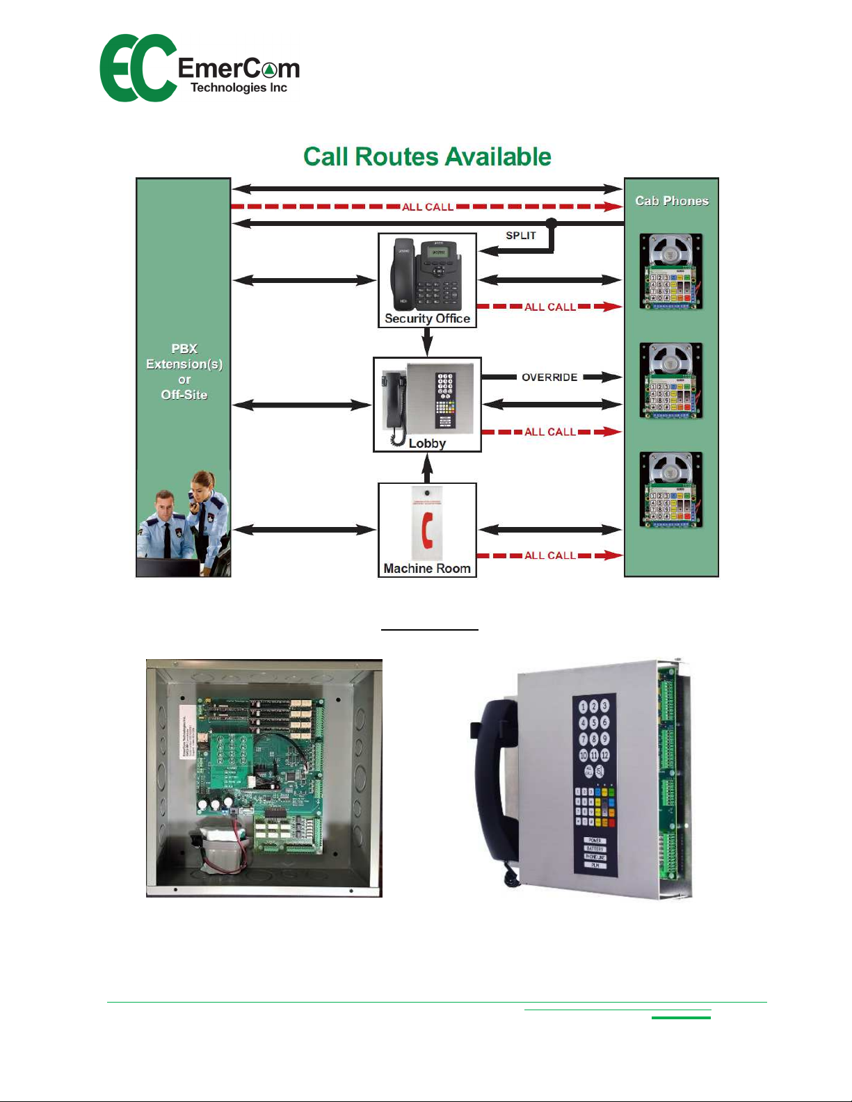
“Call Anywhere” (see Call Routes Available on page 2)
Call off-site, via an available phone line, using any on-site phone
Simple SD card firmware upgrades enable feature flexibility with optional
customization
Digital chip platform
Self-diagnostics continuously monitor its own operation and its environment
Compatible with a wide range of power supply voltages (AC and DC)
Vandal-resistant #16-AWG Brushed Stainless Steel
Box width 14.25" to fit (recess) between wall studs
Status and alarm messages displayed on Remote Phone CID
- 7 -
Page 8
EMCS User Guide
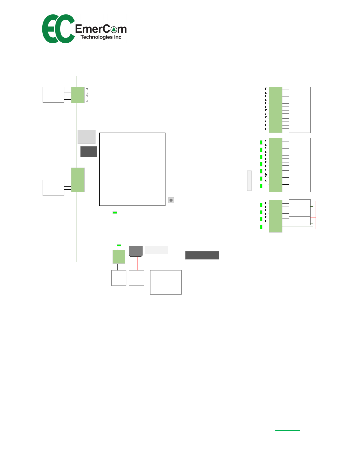
2. Circuit Board Layout & Connections
analog
phone lines
Remote
handset
(EMC-MR)
TEL LINE
SD CARD
HANDSET
EmerCom Technologies Inc.
1 2
DOORHOOK MR
3A FUSE
RESET
TO EMC- EXP
EMCS-PIM R5
Input Voltage Range:
16VDC-32VDC
16VAC- 24VAC
D5
PWR IN
-BAT+
Fast Acting
Battery Specifications:
8.4V NiMH 3800mAh
VIDEO TRIGGER
TO EMCS-CSM
TO EMC- ALRM
TO CABS
1 6 5 4 3 2 1
123+PWR- 6 5 4 3 2RST
elevator
phones
video
triggers to
building
Video
Management
System
PLM-ALRM
group 1
PLM-ALRM
group 2
PLM-ALRM
group 3
16.5Vac
SLA
Battery
Connect
ground wire to
ground lug
- 8 -
Page 9

EMCS User Guide
3. Description of Operation:
In the event of an entrapment or other emergency, an elevator occupant may press
the “phone” button on the elevator control panel, causing the elevator phone to
automatically call for help. In TEL mode the Consolidator routes the call to either of
two phone lines connected or to the Consolidator then a phone line in sequence in
Intelli-Split mode or to the Consolidator in Lobby mode. The applicable elevator icon
will turn green.
If the call is not acknowledged within a reasonable time, the phone is required to
automatically hang up and dial a second phone number. If the phone line is busy,
the Consolidator will notify the parties on the original call that another call is waiting.
The Consolidator can call into any of the elevator phones. The caller selects which
cab by touching the appropriate icon which lights-up as soon as the consolidator
door is opened. If an icon is illuminated green the cab phone is busy on a call which
can be overridden by any of the in-building handsets.
Remote/Machine Room handsets can call into any cab, even overriding emergency
calls or joining another internal call in progress.
ALL CALL (system-wide paging) is available from all internal handsets as well as
from off-site.
Phone Line Monitoring (PLM) verifies the operation of the external phone lines as
well as the lines from each cab. Cabs are assigned to groups using the quick
program keys, with 3 group alarm relays available for every 6 cabs. Each relay
signals the appropriate EMC-ALRM board. Group “0” phones do not activate PLM
alarms.
Video trigger relays indicate whenever an emergency call from a cab is in progress.
- 9 -
Page 10

EMCS User Guide
4. Diagnostics
4.1 Learn Mode
Learn mode automatically validates the wired communications system and configures
the operating mode selected by the user.
Detects the number and position of active cabs wired to the Consolidator
Verifies the operating mode selected (TEL, Lobby or Intelli-Split) by detecting the
number of valid phone lines wired to the system
Automatically configures EMC-60 phones “Consolidator Compatibility” mode
In the case of any elevator phone exhibiting unusual behaviour the
corresponding cab icon illuminates “RED” to flag the phone as “Failing to
Connect”. Note: “Failing to Connect” followed by a second attempt to
communicate will generate a PLM alarm unless the elevator phone is assigned to
PLM group #0.
4.2 Self-diagnostics
The Consolidator continuously monitors the operation of the communications system,
reporting call routing status, phone line availability and any alarm conditions. These
conditions can be observed on the display at the Consolidator or the CID display of an
on-site remote handset or heard by lifting the consolidator handset and touching
<ALARM STATUS>, or remotely through programming mode.
Routing status prompts
o Station #x is in conversation
o No available phone lines
o Phone line #y is unavailable
o Off-site ALL CALL in progress
Alarm conditions:
o Normal
o No mains power
o No battery
o Low battery
o Charging battery
o Fault battery
o Phone line fault
o Station #n fault
o PLM fault
- 10 -
Page 11

EMCS User Guide
No mains power
POWER
FLASHING
Alert
every 0.5 s
Problem Alarm
Battery issue (check ALARM STATUS) BATTERY FLASHING Alert every 0.5 s
No cab phone response in 24hours STATION ICON RED Alert every 30 s
Any of the expected phone lines not operational
(TEL mode)
No cab phone response in 24hours (if phone not
group 0)
All expected phone lines not operational (TEL Mode)
PHONE LINE RED Alert every 0.5 s
PLM RED Alert every 30 s
LED
status
Buzzer
status
4.3 PLM (Phone Line Monitoring)
The Phone Line Monitoring (PLM) feature verifies the operability of the end-to-end
communications link (e.g. for elevator phone connecting to a live phone line) as required
by ASME A17.1/CSA B44 Code. Any fault detected generates an audible and visual
alert in the elevator lobby for the assigned group (elevator phones assigned to group #0
will not generate a PLM alarm). In an alarm state the communication link is re-tried
every five minutes until the failed status is cleared.
4.4 Phone LINE TEST
A phone LINE TEST feature enables on-site personnel who have access to the
consolidator keypad to go off-hook, listen for dial tone and call any number to test the
phone line operability. A similar off-site calling feature is available from any on-site
remote handset.
- 11 -
Page 12

EMCS User Guide
5. Additional Features
5.1 Overriding an emergency call
The Consolidator overrides off-site calls in accordance with ASME A17.1/CSA B44
“Safety Code for Elevators and Escalators”. Lift the handset and touch the icon
corresponding to the active off-site conversation (illuminated in GREEN). The handset
will take over the existing conversation, connecting directly to the elevator phone after
notifying all parties before overriding the off-site connection.
On-site remote phones can also override off-site conversations by following the
selection prompts. If an on-site conversation is in progress, subsequent on-site
handsets will join the active conversation.
5.2 System-wide paging (ALL CALL)
The all system page (ALL CALL) is available by dialing in from off-site or it can originate
from on-site using either the handset and touchpad or by following the voice prompts
using any remote/on-site phone. Once connected, the operator can broadcast to all
elevator phones simultaneously. On-site initiated calls have a higher priority than those
originating from off-site and override (similar to the process described in 5.1).
5.3 Internal Calling
Remote phones can call the Consolidator by following the extended voice selection
prompts – providing a convenient feature when communicating from a machine room
where cellphone service is unavailable to a “helper” in the lobby.
5.4 Non-emergency off-site calls
Any internal phone (the EMCS handset or any remote phone) can be used to call offsite in case of an emergency or for Customer Care (1-844-363-7266) via an available
phone line. Note: The Consolidator considers these calls to have non-emergency
priority which are automatically overridden by calls initiated by entrapment events.
5.5 Video Triggering
The Consolidator has one pair of potential-free, normally open contacts for each cab
phone, which close during an emergency call to signal a video management system to
display/record the video as required. An additional relay contact closes when there are
no emergency calls in progress.
Note: Not activated during “Learn”, “PLM check” or “ALL CALL”.
- 12 -
Page 13

EMCS User Guide
6. Programming
6.1 Summary Table
The following section 6.2 provides more detailed information on each command.
Cmd # Command Range Default
1 Learn Mode
- prompted to select
Operating Mode
2 Operating Mode 0 = Lobby Mode
3 Phone Lines Available 1 digit; values 0,1,2 1
4 Active Stations 0 – 6 (or 1-12 with EMCS-EXP) 1,2
5 Inactive Stations 0 – 6 (or 1-12 with EMCS-EXP) 3,4,5,6
6 Serial Number Playback Replay only Pre-set
7 Main Firmware Version Replay only Pre-set
8 Alarm Status Playback Replay only, one or more of the following
0 = Lobby Mode (automatic if no phone
lines are available)
1 = TEL Mode (if 1 or 2 phone lines)
2 = Intelli-Split (if 1 or 2 phone lines)
1 = TEL Mode
2 = Intelli-Split Mode
“NO MAINS POWER”
“NO BATTERY”
“LOW BATTERY”
“CHARGING BATTERY”
“NORMAL”
“PHONE LINE FAULT”
“STATION NUMBER #n FAULT”
N/A
1
N/A
9 Access Code 5 digits; values 1,2,3,4,5,6,7,8,9,0 12345
10 Language 0 = English
1 = French
14 Auto Answer 0 = OFF (ignore incoming on phone line)
1 = ON
0
1
- 13 -
Page 14

Cmd # Command
EMCS User Guide
Range
Default
23 Ring Phone Extension 0 = OFF (incoming will not ring remote)
0
1 = ON (remote phone rings on incoming
call – required for CID alarm display)
24 Caller ID Update Timer 1-30 minutes (alarm reporting frequency) 1
25 Start PLM Test 1 = CONFIRM N/A
26 PLM Check Interval 0 = 12 hours
0
1 = 5 hours
30 Handset Volume Setting 0 = soft, 9 = loud 5
31 Handset Mic. Sensitivity 0 = least sensitive; 9 = most sensitive 5
32 TEL1 Line boost 0 = min; 9 = max boost 2
33 TEL 2 Line boost 0 = min; 9 = max boost 2
34 Rem. Phone attenuation 0 = min.; 8 = max attenuation 4
43 Factory Reset 1 = CONFIRM N/A
44 Remote Silence Buzzer 1 = CONFIRM N/A
45 PIM Firmware Version Replay only Pre-set
46 CSM Firmware Version Replay only Pre-set
47 CSM Hardware Version Replay only Pre-set
50 PLM Group 0 (OFF) 1-6 (or 1-12 with EMCS-EXP) -
51 PLM Group 1 1-6 (or 1-12 with EMCS-EXP) default All cabs
52 PLM Group 2 1-6 (or 1-12 with EMCS-EXP) -
53 PLM Group 3 1-6 (or 1-12 with EMCS-EXP) -
54 PLM Group 4 (only with EMCS-EXP) 1-12 -
55 PLM Group 5 (only with EMCS-EXP) 1-12 -
56 PLM Group 6 (only with EMCS-EXP) 1-12 -
60 EMCS ID 0-9 (set > 0 if more than one EMCS) 0
- 14 -
Page 15

EMCS User Guide
6.2 Programming Details
Lift the handset and touch <WAKE> to turn on the keypad and illuminate the “WAKE”
LED or call into the Consolidator from a remote location (on- or off-site) (see next
section for remote programming). Touch <PROG> to enter program mode and turn-on
the “PROG” LED. The operator prompt “Program” will be heard.
Touch the key(s) to select the command number required, touch <ENTER> and listen
for the prompt to confirm the command. Input the parameter and touch <ENTER>. The
prompt “Input accepted” will be heard if the parameter qualifies or “Incorrect entry,
please re-enter” if not. To check any entry, touch the command number followed by
<REPLAY>. Touch <CANCEL> to exit a command without changing the parameter.
Touch <EXIT> or hang-up the handset to leave programming mode. An audible alarm
will sound if the handset is off-hook too long without activity.
REPLAY
To check the current value of any parameter, enter the command number followed by
the <REPLAY> key. For example, to hear the main firmware version, press the <7> key
followed by <REPLAY>. One will then hear the message “Firmware version” followed by
the digits representing the firmware version installed on your unit.
6.2.1
Command # 1: LEARN MODE
Learn mode automatically configures and verifies the wired communication system. The
Consolidator first checks the number of valid phone lines wired to the system and
announces the operating modes available for selection. Then the Consolidator searches
for all cab phones connected to the system and displays the status of each phone as a
colour on the corresponding station icons. Cabs which exhibit unacceptable behaviour
are flagged RED for failed and trigger a Phone Line Monitoring (PLM) alarm in their
group.
Enter Learn Mode through the programming menu or by touching the <LEARN>
shortcut key. The voice prompt “Learn Mode” will be heard, followed by a choice of
available operating modes based on the wiring configuration. Touch the digit
corresponding to the desired mode followed by <ENTER> to confirm. The voice prompt
“Configuration complete” will be announced at the end of the process. Hang-up.
Voice Prompt: “Learn mode”
- 15 -
Page 16

EMCS User Guide
6.2.2
Command # 2: OPERATING MODE
The Consolidator routes conversations according to site requirements. In “Lobby mode”,
emergency calls from the cabs are directed to all in-building “authorized personnel”
handset locations. “TEL mode” directs calls off-site via the wired phone line(s). In
“Intelli-split mode”, emergency calls are directed to either in-building or off-site
“authorized personnel” locations, depending on line availability.
Voice Prompt: “Operating mode”
6.2.3
Command # 3: PHONE LINES AVAILABLE
This sets the number of valid phone lines wired to the system. The “Learn mode” autoconfiguration setting can be overridden manually.
Voice Prompt: “Phone lines available”
6.2.4
Command # 4: ACTIVE STATIONS
The station numbers of active cabs are assigned using this command. Input each
station number to be activated followed by <ENTER> or touch <REPLAY> to hear a list
of all cabs currently assigned. The “Learn mode” auto-configuration setting can be
overridden manually.
Voice Prompt: “Active stations”
6.2.5
Command # 5: INACTIVE STATIONS
Use this command to unassign cabs by inputting the station number followed by
<ENTER> or touch <REPLAY> to hear a list of inactive cabs. The “Learn mode” autoconfiguration setting can be overridden manually.
Voice Prompt: “Inactive stations”
6.2.6
Command # 6: SERIAL NUMBER PLAYBACK
Factory set. Use the serial number playback command to report the serial number (as
displayed on the sticker attached to the main circuit board).
Voice Prompt: “Serial number”
6.2.7
Command # 7: MAIN FIRMWARE VERSION PLAYBACK
Replays the Consolidator’s main circuit board firmware version.
Voice Prompt: “Firmware version”
- 16 -
Page 17

EMCS User Guide
6.2.8
Command # 8: ALARM STATUS PLAYBACK
The <ALARM STATUS> touch key and “Alarm Status Playback” command report the
system alarm status (power, battery, TEL line and cab phone condition).
Voice Prompt: “Alarm status”
Note: The battery is a rechargeable NiMH battery and should have a full charge within 1
day of connecting the Consolidator to AC power. Replace with a factory-supplied battery
if the alarm status indicates a dead battery or once every 5 years.
6.2.9
Command # 9: ACCESS CODE
Entry of a 5-digit access code will be required for remote programming. Changing the
access code to a unique number will prevent others calling in and modifying the
settings. Default is 1 2 3 4 5.
Caution: Programming by calling in remotely will not be possible without the access
code.
Voice Prompt: “Access code”
6.2.10
Command # 10: LANGUAGE
The Consolidator has built-in voice prompts to assist emergency personnel when an
emergency call is in progress and to assist during programming. Set to either English
(0) or French (1).
Voice Prompt: “Language”
6.2.11
Command # 14: AUTO ANSWER
The auto answer setting determines whether the Consolidator accepts off-site calls from
either phone line.
Voice Prompt: “Auto answer”
- 17 -
Page 18

EMCS User Guide
6.2.12
Command # 23: RING PHONE EXTENSION
This command enables signaling from the Consolidator to on-site remote locations.
When turned on, remote phones attached to the MR terminal will ring and display
emergency call and alarm status information on the CID screen.
Voice Prompt: “Ring phone extension”
6.2.13
Command # 24: CALLER ID UPDATE TIMER
Alarm status information is displayed on every on-site remote phone CID screen and
updated at intervals defined by this timer (in minutes).
Voice Prompt: “Caller ID update timer”
6.2.14
Command # 25: START PLM TEST
To simulate a cab phone failure, set the PLM test on the EMC-60 cab phone
(Command 24) to 1 - 100s, which de-energize the PLM alarm relay for the time
selected. Start the EMCS PLM test (touch 1 to confirm) to activate the alarm.
The EMCS will check the status every minute until the EMC-60 PLM alarm resets.
Voice Prompt: “PLM test”
6.2.15
Command # 26: PLM CHECK INTERVAL
The ‘PLM Check Interval’ sets the test frequency (Code requires at least once per day)
When PLM Check Interval = 0, the EMCS executes a full PLM check every 12 hours.
When PLM Check Interval = 1, the EMCS executes a full PLM check every 5 hours.
Voice Prompt: “PLM check interval”
- 18 -
Page 19

EMCS User Guide
6.2.16
Command # 30: HANDSET VOLUME SETTING (not EMCS-MR)
The “Volume Setting” command sets the volume of the Consolidator handset speaker.
Voice Prompt: “Volume”
6.2.17
Command # 31: HANDSET MIC. SENSITIVITY (not EMCS-MR)
This sets the Consolidator handset microphone sensitivity. 0 = least sensitive; 9 = most
sensitive.
Voice Prompt: “BEEP”
6.2.18
Command # 32 & # 33: PHONE LINE #1 / #2 BOOST
“Phone Line Boost” will amplify the signal for soft/quiet phone lines.
Contact Customer Care (1-844-363-7266) for additional information.
Voice Prompt: “BEEP”
6.2.19
Command # 34: REMOTE PHONE ATTENUATION
For communication from “noisy” Machine Rooms, “Remote Phone Microphone
Attenuation” reduces the handset microphone path volume to the elevator phone to
reduce “chopping” and improve 2-way communication.
Voice Prompt: “BEEP”
6.2.20
Command # 43: FACTORY RESET
All parameters are reset to factory default. Enter <1> to confirm.
Voice Prompt: “Factory parameters reset”
6.2.21
Command # 44: REMOTE SILENCE BUZZER
“Remote Silence Buzzer” will remotely mute the Consolidator buzzer and the CID
alarms. (or silence the buzzer with the “silence” button on the consolidator)
Voice Prompt: “Silence buzzer”
- 19 -
Page 20

EMCS User Guide
6.2.22
Commands # 50 to # 56: PLM GROUP ASSIGNMENT (EMC-MR)
Command #50 allocates the cab specified (1-12) to group 0 (no alarm).
Command #51 allocates the cab specified (1-12) to group 1 (default).
Command #52 allocates the cab specified (1-12) to group 2.
Command #53 allocates the cab specified (1-12) to group 3.
Command #54 allocates the cab specified (1-12) to group 4.
Command #55 allocates the cab specified (1-12) to group 5.
Command #56 allocates the cab specified (1-12) to group 6.
Examples: To allocate cab #4 to PLM group #2, in programming mode,
touch 52 <ENTER> 4 <ENTER>.
Touch 52 <REPLAY> to list all cabs assigned to group 2.
All cabs are assigned to Group #1 by default and need to be pulled to their new Group.
Cabs assigned to Group #0 are ignored by the daily PLM check.
Voice Prompt: “PLM Group”
6.2.23
Command # 60: EMCS ID
A unique ID must be assigned to each Consolidator if more than one are connected in
the system. Use default ID = 0 for systems with only one Consolidator.
Voice Prompt: “EMCS ID”
- 20 -
Page 21

EMCS User Guide
6.3 Remote Programming
Lift the EMC-MR/Remote Phone handset. If an internal emergency call or an internal
ALL CALL or an internal non-emergency call is already in-progress, the EMC-MR will
join the call; otherwise the Consolidator will answer with one of the following prompts:
“Station number #x is in conversation”
“No available phone lines”
“Phone line number #y is unavailable”
“Off-site ALL CALL in-progress” or
“Select the station number you wish to speak to followed by the star (*) key, or
select star-star (**) for further options”
- Select star-star (**)
“Select nine-star (9*) to call off-site, zero-star (0*) to call the lobby,
select star-star (**) to initiate an all system page or enter the
access code for programming mode” (factory default is 12345)
- Enter the access code, to which the Consolidator will respond “Program”
followed by a confirmation beep unless the access code is incorrect, in
which case the prompt “Incorrect entry, please re-enter” will play.
In remote programming, key sequences exist to replicate the functions found on the
Consolidator keypad. Use the following table to look-up the equivalent remote key
sequence for the different keypad functions:
Keypad Equivalent Remote Sequence
PROGRAM 99* + “Access Code”
CANCEL *1
ENTER **
REPLAY #
EXIT *9
- 21 -
Page 22

EMCS User Guide
7. Precautions
Always follow basic safety precautions when using your telephone equipment to reduce the risk
of fire, electrical shock, and injury.
1. Read and understand all instructions in the User Guide.
2. Read all warnings and follow all instructions.
CAUTION – Do not replace the batteries with alkaline batteries. Use only an
identical rechargeable battery or a battery recommended and supplied by the
manufacturer.
system not used for long periods.
3. Do not use liquid or aerosol cleaners.
4. Do not use the telephone near water, a bathtub, wash bowl, kitchen sink, laundry tub,
swimming pool or in a wet basement.
5. Use only the type of power source supplied by the manufacturer or specified in these
instructions (must be current-limited to class 2). If you are not sure of the type of
substitute power supply, consult your dealer or the manufacturer.
Unplug the battery if the mains power will be disconnected and the
6. Never spill liquid on the telephone equipment.
7. Do not disassemble this product unless qualified to do so. Opening or removing covers
may expose you to dangerous voltages or other risks. Incorrect reassembly can cause
electrical shock.
8. Do not overload outlets and extension cords if connecting the phone to AC power from
an outlet. Overloading the outlets can result in fire or electric shock.
9. Avoid using a telephone during a local thunderstorm due to the potential risk of electrical
shock from lightning.
10. Do not use a telephone to report a gas leak in the vicinity of the leak.
11. Notify a building official if:
• Liquid has been spilled into the telephone equipment
• The telephone equipment has been exposed to rain or water
• The telephone equipment exhibits a distinct change in performance.
CAUTION – Always disconnect the battery, power supply and telephone lines from
the source before servicing this equipment
12. Save these instructions
Customer Care: Call 1-844-EMERCOM (1-844-363-7266) for assistance.
- 22 -
Page 23

EMCS User Guide
8. Mechanical
8.1 Dimensions
EMCS
Backbox: 14.25” (362 mm) wide x 10.50” (268 mm) high x 3.15” (80 mm) deep for
surface mounting or recessing between studs
Overall: 14.50” (368 mm) wide x 11.16” (283 mm) high x 3.50” (89 mm) deep
EMCS-MR
Overall: 12” wide x 12” high x 4” deep
- 23 -
Page 24
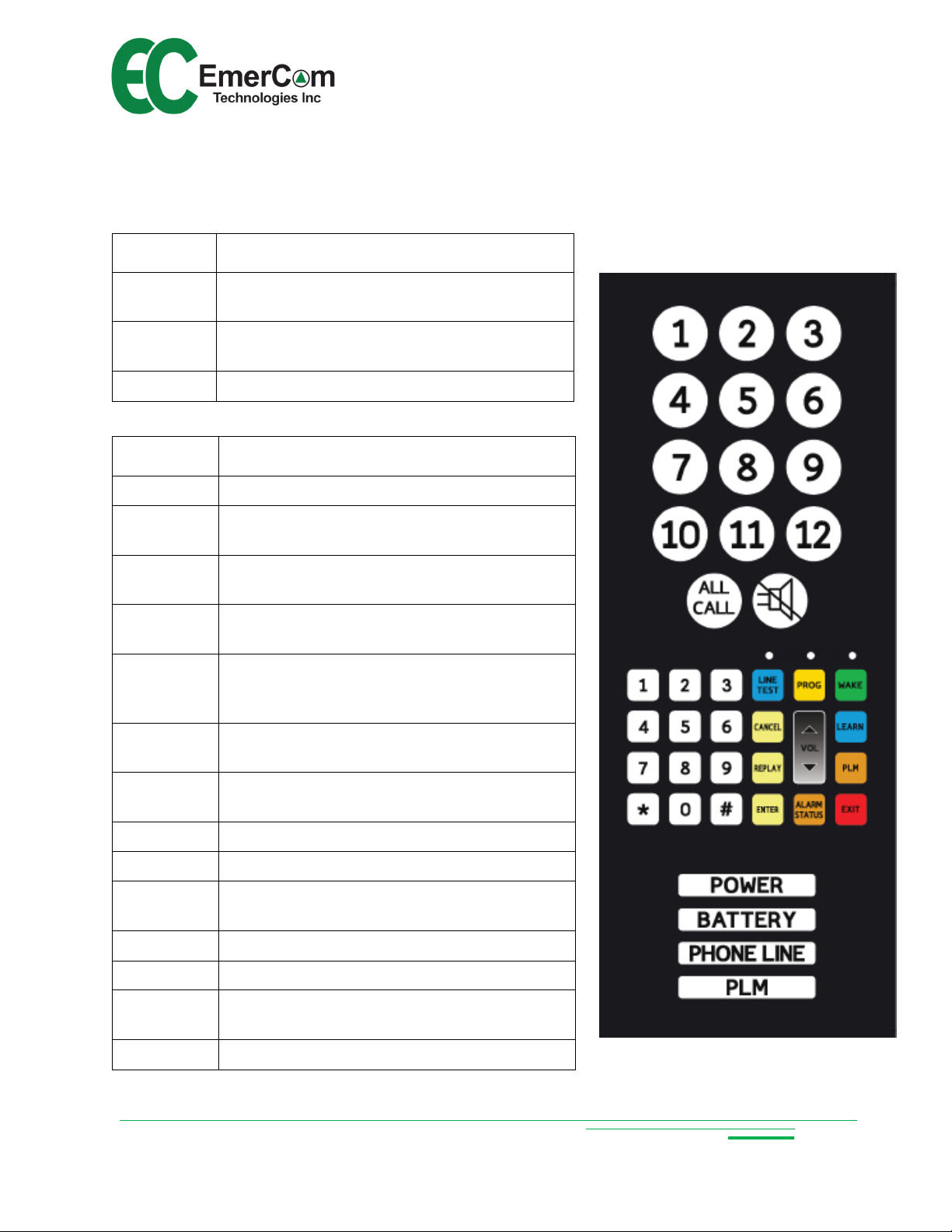
9. Keys and Indicators
9.1 Keypad
Key + Icon Description
EMCS User Guide
1 - 12
ALL CALL
SILENCE Silences alarm buzzer
Key Description
0 - 9 Numeric keys 0 through 9
< * > < # >
<WAKE>
<PROG>
<LINE
TEST>
<CANCEL>
Stations 1 to 12 (illuminated when door is
open if wired-up and configured)
Pages all active cabs, allowing the operator
to broadcast a message
Special characters used in program
command sequences
Wake up keypad from sleep mode when
handset is off-hook (Wake LED turns on)
Enters program mode when handset is offhook and the keypad is awake (LED on)
When keypad awake, enables the handset
to call out to test the phone line (LED turns
on)
Clears/cancels current entry OR returns to
the program menu
<REPLAY>
<ENTER> Accepts current command or entry
<VOL ↑> Increments handset volume by one (up to 9)
<VOL ↓>
<LEARN> Auto-configuration quick key
<PLM> Quick configuration of cabs into PLM groups
<ALARM
STATUS>
<EXIT> Exits out of programming mode
Plays back entry if valid command # is
entered
Decrements handset volume by one (down
to 1)
Plays “NORMAL” or lists active alarms
- 24 -
Page 25

EMCS User Guide
9.2 LEDs and Indicators
The EMCS touchpad attached to the inner door has:
13 cab phone icon indicators (in-conversation = green; pending action = orange;
fault = red; no phone detected = off)
3 programming keypad LEDS
o Wake (programming keypad awake = green)
o Program mode (green)
o Line test (test call in progress = green)
4 alarm status indicators (as described in 4.2)
o POWER (mains off = red)
o BATTERY (alarm pending = red)
o PHONE LINE (fault = red)
o PLM (alarm pending = red)
There are 13 PCB-mounted LEDs present on the main circuit board under the service
panel. These LEDs provide essential diagnostic and status information at a glance:
1. Heartbeat D5 (pulsing green) (located above the large capacitors in the bottom
left quadrant of the main board)
2. Power (input PWR present = green)
3. 3 x PLM (normal = green; fault = off) (located below the silkscreen label “TO
EMC-ALRM”)
4. PLM-PWR (output power present = green)
5. 6 x Video Triggers (idle = off; in-use = green)
6. 1 x Video Reset (idle = on; any cab in-use = off)
10. Ordering
Model and description
EMCS-BASE - High Rise for 6 cabs + 3 PLM groups + 6 video triggers in ss enclosure
with handset
EMCS-MR - EMCS-BASE without handset for machine room mounting
EMCS-OEM - EMCS-BASE without enclosure for mounting in lobby panel
EMCS-FR - EMCS-BASE in ss enclosure with handset and 2 or 3 position Fire Recall
switch
EMCS-EXP - for expansion to 7-12 cabs + 4-6 PLM groups + 7-12 video triggers
- 25 -
Page 26

11. Specifications
EMCS User Guide
Elevator Wiring
Requirements:
Phone Line Requirements:
Number of Phone Lines 2
Number of concurrent calls 2
Capacity (number of elevator
phones)
Integrated Phone Line
Monitoring (PLM)
Integrated Video triggers
Power Supply (supplied)
One shielded pair of communication cable,
minimum 24AWG, with the shield grounded at one
end only, preferably the controller-end of the
traveling cable.
Standard analog loop-start voice grade telephone
line.
6 (six) or 12 (twelve) with EMCS-EXP module
(expandable)
up to 3 groups for 6 phones or
6 groups for 12 phones (with EMCS-EXP module)
Potential free contact per cab (6 or 12)
Potential free contact for video reset (1)
Class 2; 120V AC, 60Hz input; 16.5V AC, 40W
output
Backup Power
(Used if AC power is cut off)
Operating Range 0 – 60°C
Ringer Equivalence (REN) 0.1B
Dimensions
8.4V/3800 mAh rechargeable NiMH battery.
Replace every 5 years or as required (factory
supplied).
EMCS Backbox: 14.25” (362 mm) wide x 10.50”
(268 mm) high x 3.15” (80 mm) deep for surface
mounting or recessing between studs
EMCS Overall: 14.50” (368 mm) wide x 11.16”
(283 mm) high x 3.50” (89 mm) deep
EMCS-MR: 12” wide x 12” high x 4” deep
- 26 -
Page 27

EMCS User Guide
12. Warranty
SHIPPING AND LIABILITY
Please verify that the shipment is received in good order ASAP.
EmerCom Technologies Inc warrants parts and labor on all equipment of its own
manufacture for a period of 24 months from the date of shipment but cannot be held
liable for any loss or damage resulting from causes beyond their reasonable control.
Any abuse, vandalism, alteration or misuse of these products for purposes or in a
manner other than that for which they were manufactured will void the warranty.
Please return defective products prepaid to your nearest service center after first calling
1-604-589-3899 for a Return Authorization (RMA) number. Please provide:
Model and serial number
Problem description
Name of the person requesting the RMA, phone number and shipping address.
Reference the RMA number clearly on all packaging and paperwork.
Note: Statistically, more field problems are caused by wiring, connection, installation or
programming issues rather than the phones themselves. Please have your field staff
call EmerCom from site before concluding that an EmerCom product needs to be
returned, to offer you the assistance to resolve the problem most conveniently over the
phone.
All prices are F.O.B. our warehouse. Our responsibility ceases when the transportation
company receives the material from us in good condition. Please check the shipment for
completeness and for transportation damage upon receipt. If damaged a claim must be
made with the transportation company immediately. We will provide the buyer all
assistance possible to adjust such claims.
EmerCom Technologies Inc shall not be liable for any loss or damage resulting from
causes beyond its reasonable control and in no event whatsoever shall we be liable for
consequential damages resulting in personal injuries, property damage or economic
loss to any party.
- 27 -
Page 28

EMCS User Guide
13. FCC Notice and Customer Information
This device complies with Part 68 of the FCC rules and the requirements adopted by
the ACTA. On the mounting plate of the phone is a label that contains, among other
information, a product identifier in the format US:AAAEQ##TXXXX. If requested, this
information must be provided to the telephone service provider.
FCC REQUIREMENTS
This equipment complies with TIA-968-A,-1~5 of FCC Rules. On the base unit of this
equipment is a label that contains, among other information, the FCC Registration
Number and Ringer Equivalence Number (REN) for this equipment. IF REQUESTED,
THIS INFORMATION MUST BE GIVEN TO THE TELEPHONE COMPANY.
The REN is useful to determine the quantity of devices you may connect to your
telephone line and still have all of those devices ring when your telephone number is
called. In most, but not all areas, the sum of the REN of all devices connected to one
line should not exceed five (5.0). To be certain of the number of devices you may
connect to your line, as determined by the REN, you should contact your local
telephone company to determine the maximum REN for your calling area.
If your equipment causes harm to the telephone network, the telephone company may
discontinue your service temporarily. If possible, they will notify you in advance. But if
advance notice is not practical, you will be notified as soon as possible. You will be
informed of your right to file a complaint with the FCC if you believe it is necessary. Your
telephone company may make changes in its facilities, equipment, operations or
procedures that could affect the proper functioning of your equipment. If they do, you
will be notified in advance to give you an opportunity to maintain uninterrupted
telephone service.
If you experience trouble with this telephone equipment, please contact the following
address and phone number for information on obtaining service or repairs. The
telephone company may ask that you disconnect this equipment from the network until
the problem has been corrected or until you are sure that the equipment is not
malfunctioning.
COMPANY: EmerCom Technologies Inc.
ADDRESS: 121 – 3989 Henning Drive, Burnaby, BC, V5C 6P8
TEL NO.: 1-844-EMERCOM (1-844-363-7266)
This phone equipment contains no customer or user serviceable parts. Attempting to
repair this equipment yourself will void the user’s warranty. All repairs should be
referred to the Customer Care Center at 1-844-EMERCOM (1-844-363-7266) to
determine if the phone equipment needs to be returned.
- 28 -
Page 29

EMCS User Guide
This equipment may not be used on coin service provided by the telephone company.
Connection to party lines is subject to state tariffs. Contact your state public utilities
commission, public service commission or corporation commission for information.
This equipment does not provide for data operation.
JACK (USOC): hardwired
RINGER EQUIVALENCE = 0.1 Class B
Facility Interface Code (FIC) = 02LS2
Service Order Code (SOC) = 9.0y
Caution - This equipment cannot report an alarm when other equipment (telephone,
answering system, fax, etc.) connected to the same phone line is in use. If the phone
line is shared with other users, ensure the priority of the emergency call is maintained. If
in doubt, please contact us at 1-844-EMERCOM (1-844-363-7266).
Caution - To ensure proper operation, this equipment must be installed according to the
enclosed installation instructions. To verify that the equipment is operating properly and
can successfully report an alarm, this equipment must be tested immediately after
installation, and periodically thereafter, according to the enclosed test instructions.
WHEN PROGRAMMING EMERGENCY NUMBERS AND/OR MAKING TEST CALLS
TO EMERGENCY NUMBERS:
1) Remain on the line and briefly explain to the dispatcher the reason for the call.
2) Perform such activities in the off-peak hours.
- 29 -
Page 30

EMCS User Guide
14. Industry Canada Certification
NOTICE:
This equipment meets the applicable Industry Canada Terminal Equipment Technical
Specifications. This is confirmed by the registration number. The abbreviation, IC
before the registration number signifies that registration was performed based on a
Declaration of Conformity indicating that Industry Canada technical specifications were
met. It does not imply that Industry Canada approved the equipment.
Le présent matériel est conforme aux spécifications techniques d’Industrie Canada
applicables au matériel terminal. Cette conformité est confirmée par le numéro
d'enregistrement. Le sigle IC, placé devant le numéro d'enregistrement, signifie que
l’enregistrement s’est effectué conformément à une déclaration de conformité et indique
que les spécifications techniques d'Industrie Canada ont été respectées. Il n’implique
pas qu’Industrie Canada a approuvé le matériel.
NOTICE:
This product meets the applicable Industry Canada technical specifications.
Le présent matériel est conforme aux specifications techniques applicables d’Industrie
Canada.
The Ringer Equivalence Number (REN) is an indication of the maximum number of
devices allowed to be connected to a telephone interface. The termination of an
interface may consist of any combination of devices subject only to the requirement that
the sum of the RENs of all the devices not exceed five.
L’indice d’équivalence de la sonnerie (IES) sert à indiquer le nombre maximal de
terminaux qui peuvent être raccordés à une interface téléphonique. La terminaison
d’une interface peut consister en une combinaison quelconque de dispositifs, à la seule
condition que la somme d’indices d’équivalence de la sonniere de tous les dispositifs
n’excéde pas cinq.
Rev: 1p6
- 30 -
 Loading...