

Page 1
Copyright ©2021 Emerald Supply, Inc. All rights reserved. Publisher reserves the right to make dimension or
specification changes, or deletions, consistent with design trends, product improvements, or for reasons
beyond our control. Publisher makes no warranties with respect to the accuracy or completeness of the
contents of this manual.
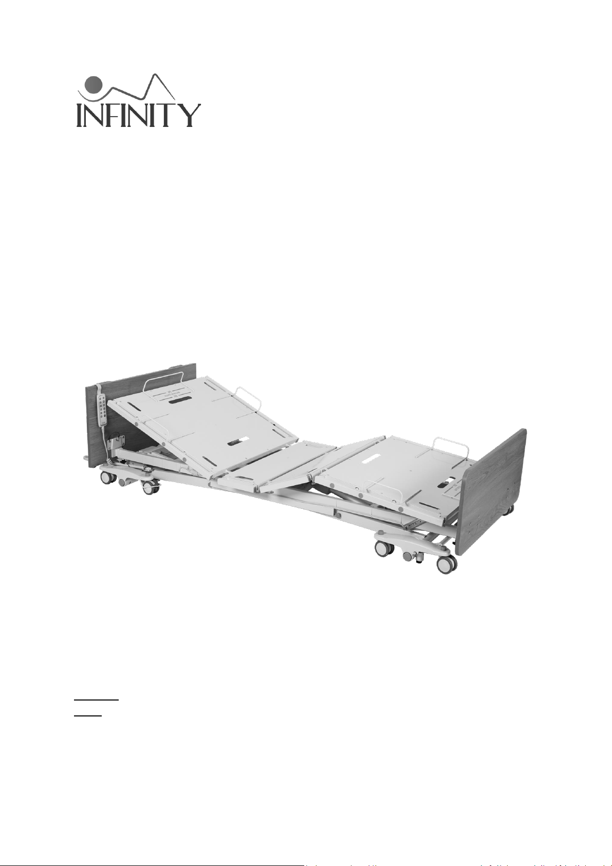
Long-Term Care Low Profile Bed
Model 54000
User Manual
DEALERS: This manual MUST be given to the user of the bed.
USER: Before using this bed, read this manual and save for future reference.
Page 2

1
Table of Contents
GENERAL INFORMATION ................................................................ 2
STANDARD SYMBOLS AND WARNING LABELS ................................................ 2
INTENDED USE ........................................................................................ 3
SAFETY PRECAUTIONS .............................................................................. 3
TECHNICAL SPECIFICATION ............................................................. 9
EQUIPMENT ASSEMBLY ................................................................ 10
UNPACKING THE BED ............................................................................. 10
ASSEMBLING THE BED ............................................................................ 11
EQUIPMENT OPERATION .............................................................. 15
POSITIONING THE BED ............................................................................ 15
EXTEND THE LENGTH OF THE BED FROM 80” TO 88” .................................... 16
EXTEND THE WIDTH OF THE BED FROM 35” TO 42” OR 48” .......................... 16
ADJUSTING THE EXTENDED HEEL LIFT ........................................................ 17
USING THE CONTROLLER ......................................................................... 18
RESETTING THE BED ............................................................................... 18
OPERATING THE BED RAILS ...................................................................... 19
TROUBLESHOOTING GUIDE .......................................................... 20
LIMITED WARRANTY .................................................................... 21
APPENDIX – SERVICE RECORD ...................................................... 22
Page 3

2
GENERAL INFORMATION
Standard Symbols and Warning Labels
Warnings
Signal words with symbols are used in this manual to highlight hazards or unsafe practices
which could result in personal injury or property damage. See the information below for
definitions of the signal words and symbols.
DANGER
Danger indicates an imminently hazardous situation which, if not avoided, will result
in death or serious injury.
WARNING
Warning indicates a potentially hazardous situation which, if not avoided, could
result in death or serious injury.
CAUTION
Caution indicates a potentially hazardous situation which, if not avoided, may result
in property damage or minor injury or both.
IMPORTANT
Indicates a hazardous situation that could result in damage to equipment or property
if it is not avoided.
Gives useful tips, recommendations and information for ease of use.
Page 4

3
Intended Use
The Infinity Long-Term Care Low Profile Bed is intended for use within an institutional
healthcare environment, i.e. nursing homes, rehabilitation care, assisted living.
The bed is NOT a transport device. The wheels on the bed are for positioning the bed
only. These shall be locked at all times when carrying a patient.
The beds are intended for users who fully understand the content of this manual and
is not intended for use by children.
Safety Precautions
Assembling the Bed
WARNING
Make sure all attaching hardware is securely tightened.
DO NOT overtighten the mounting hardware as this will damage the mounting
brackets.
DO NOT modify this equipment without authorization of the manufacturer. Doing so
will void the warranty.
DO NOT use accessories that are not designed or approved for use with the bed.
Operating the Bed
WARNING
DO NOT operate your bed until it is fully assembled and checked.
DO NOT exceed maximum weight limitations of the bed.
ALWAYS make sure the power cable is clear of any moving parts of the bed before
switching on the power.
ALWAYS keep hands and fingers away from moving parts to avoid injury.
Page 5

4
ONLY use appropriate mattresses and ALWAYS adjust the mattress retainer system
accordingly to ensure the mattress is fixed in place.
The mattress must be properly sized to meet entrapment zone dimensional
guidelines published by the FDA.
The mattress platform shall be kept in a flat position if the patient’s condition could
lead to patient entrapment.
ALWAYS keep the bed at the lowest position when the patient is unattended.
Never permit anyone under the bed at any time.
Only permit one person on the bed at a time.
Do not use side rails as handles to move the bed.
The side rails may NOT be used as a restraint.
When operating/moving the bed, ensure that the resident is positioned properly
within the confines of the bed. DO NOT let any extremities protrude over the side or
between the rails when performing these functions.
Keep all moving parts free from obstruction (i.e. blankets/sheets, pads, tubing, etc.)
which may get tangled around the bed, side rails, or legs.
Weight capacity includes the total weight of the mattress, resident, bedding, head
and foot boards, side rails, and any accessories. Weight should be evenly distributed.
Do not use near explosive gases.
Possible fire hazard when used with oxygen administering equipment other than
nasal or masked type.
When using nasal or masked type administering equipment, oxygen or air tubing
MUST be routed and secured properly to ensure tubing does not become entangled,
kinked, or severed during normal operation of the bed.
Page 6

5
The Central Lock provides the resident with a stable and secure bed, providing easy
access in and out of the bed. Check that the Central Lock is engaged and the bed is
solidly in place before leaving the bed unattended or before attempting resident
transfers into or out of the bed.
The Central Lock is not intended to be used on a sloping floor or building access ramp.
Failure to comply could result in injury or death.
The Central Lock should be locked at all times except when moving the bed.
For maximum resident safety, casters should be locked at all times in addition to the
Central Locking System, except when moving the bed.
Performing Maintenance
WARNING
ONLY qualified personnel should carry out the bed maintenance.
DO NOT attempt to open the pre-sealed actuator or obtain local service, for it will
VOID the warranty and might result in damage. Consult your dealer or manufacturer
for further information.
Inspect the casters every six months to check for tightness and wear.
Regular maintenance of bed and accessories is necessary to ensure proper operation.
DO NOT overtighten mounting hardware. This will damage mounting brackets.
Unplug the power cord when performing any maintenance on the bed.
Electrical and Earthing
WARNING
EARTHING
DO NOT, under any circumstances, cut or remove the earthing prong from any plug.
Some devices are equipped with three-prong (earthing) plugs for protection against
possible shock hazards. Where a two-prong wall receptacle is encountered, it is the
personal responsibility and obligation of the customer to contact a qualified
electrician and have the two-prong receptacle replaced with a properly earthed
Page 7

6
three-prong wall receptacle in accordance with the regional and national regulations.
If you must use an extension cable, use ONLY a three-wire extension cable having
the same or higher electrical rating as the device being connected.
DO NOT use if the power cable is cut, frayed or loosely connected to the device.
Power supply cable may be damaged by inappropriate handling, e.g. by kinking,
shearing or other mechanical damages. The POWER SUPPLY CABLE is only
replaceable by SERVICE PERSONNEL.
Disposal
WARNING
This product has been supplied from an environmentally aware manufacturer.
Where backup battery is used, DO NOT dispose of batteries in normal household
waste. They MUST be taken to a proper disposal site. Contact your local waste
management company for information.
This product may contain substances that could be harmful to the environment if
disposed of in places (landfills) that are not appropriate according to legislation.
Please be environmentally responsible and recycle this product through your
recycling facility at its end of life.
Radio Frequency Interference
WARNING
Most electronic equipment is influenced by Radio Frequency Interference (RFI).
CAUTION should be exercised with regard to the use of portable communication
equipment in the area around such equipment. If RFI causes erratic behavior, switch
the power OFF IMMEDIATELY. DO NOT turn the Power Switch ON while transmission
is in progress.
Page 8
7
Reducing the Risk of Entrapment
WARNING
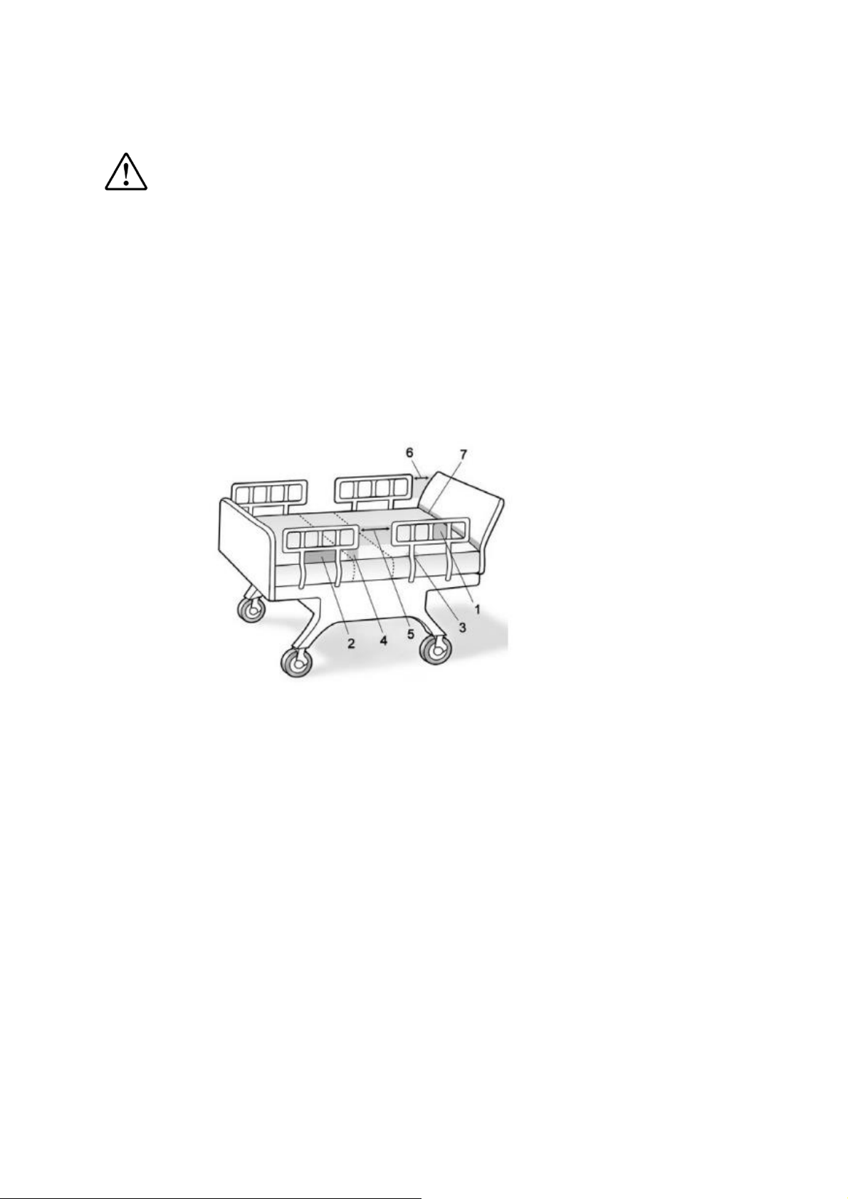
The Hospital Bed Safety Workgroup (HBSW) in partnership with the FDA has
recognized potential entrapment zones in hospital bed systems and has developed
dimensional guidance to reduce the risk of entrapment. They have identified seven
zones in the bed system where there is a potential for patient entrapment.
Entrapment may occur in flat or articulated bed positions, with the rails fully raised
or in intermediate positions. Each facility is responsible for compliance with the
entrapment guidelines. For more information about entrapment zones and
guidelines please visit the FDA website.
ENTRAPMENT ZONES:
Zone 1: Within the rail
Zone 2: Between the top of the compressed mattress and the bottom of the rail,
between the rail supports
Zone 3: Between the rail and the mattress
Zone 4: Between the top of the compressed mattress and the bottom of the rail, at
the end of the rail
Zone 5: Between the split bed rails
Zone 6: Between the end of the rail and the side edge of the head or foot board
Zone 7: Between the head or foot board and the mattress end
Page 9

8
STEPS TO PREVENT BED FIRES
• Inspect the bed’s power cord for damage.
• Connect the power cord directly into a wall-mounted outlet that is in good working
order, with no cracks or chips. The plug should fit tightly into the outlet. The ground
pin should be intact and secure.
• Do not connect the bed’s power cord to an extension cord or to a multiple-outlet strip.
• Do not cover any power cord with a rug. Heat may build up or the cord may be
damaged.
• Inspect the floor beneath the bed for buildup of dust and lint. Ask housekeeping to
clean if necessary.
• Inspect the resident’s bed controls, looking for signs of damage where liquids could
leak in.
• Test the bed and its controls, including resident lockout features, to ensure that the
bed can move freely in both directions without damaging any cords.
• Check monitors and other resident equipment for signs of overheating or physical
damage.
• Keep linens and clothes away from power sources.
• Tell maintenance staff about any unusual sounds, burning odors, or unusual
movement of a bed.
If you suspect overheating, follow your facility’s policy for fire safety and move resident to a
safe area if necessary.
Page 10

9
TECHNICAL SPECIFICATION
Model 54000
OPERATING RANGE
Bed Height
7” – 30”
Back Rest Angle
0° - 65°
Knee Break Angle
0° - 35°
Additional Manual Leg Lift
Yes, various positions
Trendelenburg / Reverse Trendelenburg
± 12°
WEIGHT
LIMIT
Safe Working Load (SWL)
Max. Patient Weight
WEIGHTS &
DIMENSIONS
Sleeping Surface Dimension
Width x Length
Caster Size
3”
Weight IN Carton
290 lbs
Weight OUT of Carton
251 lbs
ELECTRICS
Power Supply (V/PH/Hz)
100-240V/1ph/50-60Hz
Power Consumption (Max)
288 W
Number of Motors
4
Protection Class
IPX4
Insulation Class
II Type B
Duty Cycle
Interruption 10%, Max. 2 min./18min.
Battery backup
Included
ENVIRONMENT
Operating Temperature
40°F - 105°F (5°C - 40°C)
Storage Temperature
15°F – 120°F (-10°C - 50°C)
Operation & Storage Humidity
20% - 80%
Operation & Storage Atmospheric Pressure
700 - 1060 hPa
Operation & Storage Altitude
≤ 3000 m
Noise Level
< 50 db(a)
650 lbs
600 lbs
35”-42”-48” x 80”-88”
Page 11
10
EQUIPMENT ASSEMBLY
Unpacking the Bed
WARNING
To avoid injury, DO NOT attempt to remove the bed from the carton without
assistance.
I. Unpack the components from the shipping cartons.
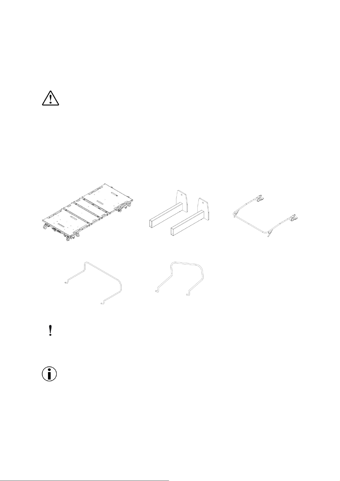
II. Upon unpacking your bed, the package should contain all of the following
components.
III. Examine exterior of the bed components for nicks, dents, scratches or damages.
Bed Assembly x 1
Head/Footboard Frame x 4
Wall Bumper Bar x 1
Bed-end Mattress Retainer x 2
Mattress Retainer x 4
IMPORTANT
Store the packaged bed in a dry area. Do not place other objects on top of the
packaged bed.
Unless the bed is to be used immediately, retain boxes, containers, and packing
materials for use in storing until use of bed is required.
Page 12
11
Assembling the Bed
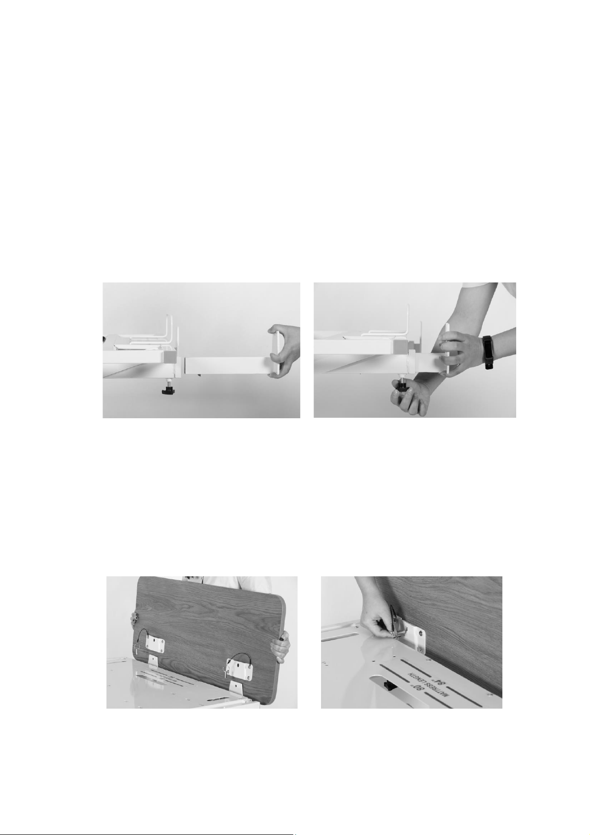
Assembling the head/foot board brackets to the bed
1. With the bed raised to its highest position, step on the locking levers to lock the
casters on at the foot end of the bed.
2. Turn and loosen the two black turn knobs on the underside of the bed assembly
insertion slots on the head side of the bed.
3. Slide and push the headboard brackets all the way into the slots. Tighten the black
knob to secure the brackets in place.
4. Repeat the same procedure for the footboard bracket installation.
Assembling the head/footboard
1. With the mounting plates on the headboard facing the bed, slide the mounting
plate groove onto the headboard mounting bracket’s vertical support.
2. Insert the lock pin through the mounting plate into the headboard to secure the
headboard in place. Repeat on the other mounting plate.
3. Repeat the same procedure for footboard installation.
Page 13
12
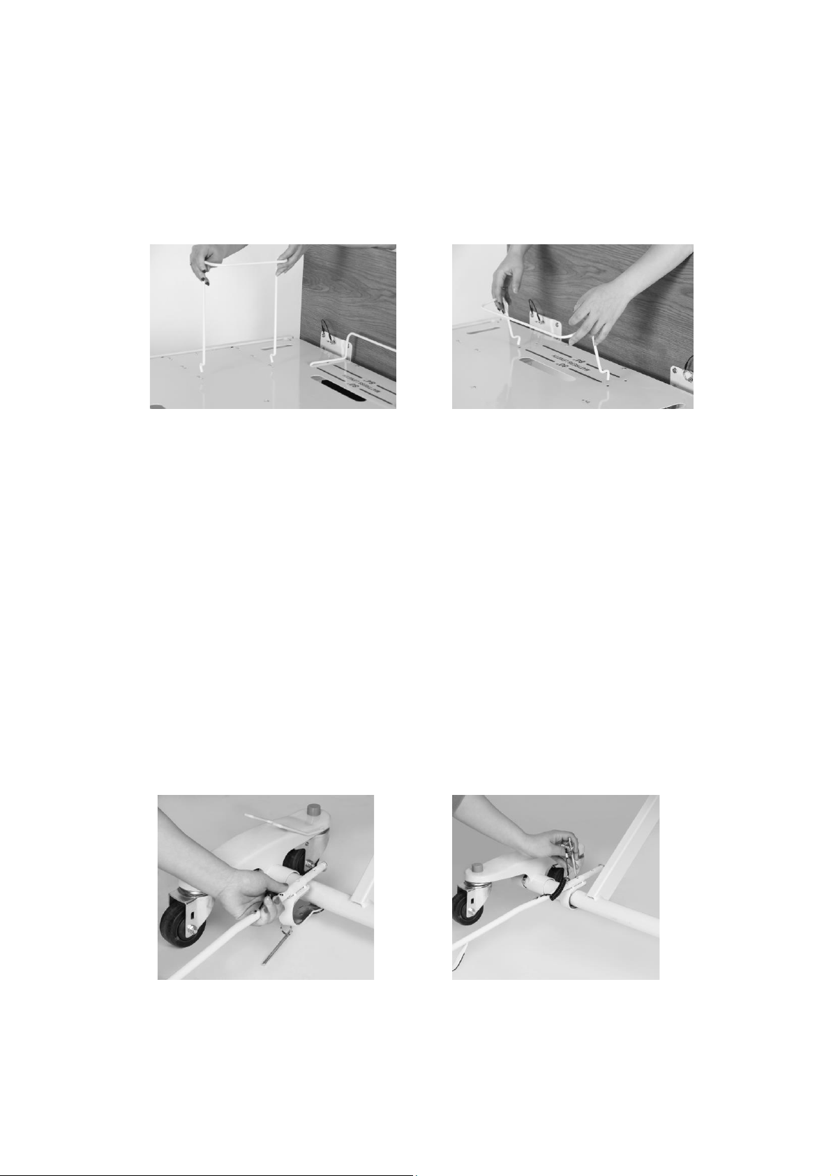
Installing the mattress retaining system
1. Locate the mounting holes for the mattress retainers in the bed deck. Align and
insert the mattress retaining wires through the pre-cast holes.
2. Repeat the procedure for all four side mattress retainers.
3. Insert the bed end mattress retainer in the foot side of the bed deck through the
precast holes.
4. Ensure that all mattress retainers are flat against the bed deck.
Certain bed models have multiple sets of holes for various bed widths and lengths.
Adjust the mounting position accordingly for different sized mattresses. The mounting
holes are labeled with the corresponding size. Ensure the mattress fits snugly within
the mattress retainers.
Installing the wall bumper bar
1. Clip the wall bumper bar assembly on to the caster support shaft at the head end
of the bed. Ensure the bumper bar foot stand is facing the floor.
2. Slide the bar to adjust the length. Insert the pin through the bar through the holes
on the bar to fix the length and lock the assembly in place.
Page 14
13
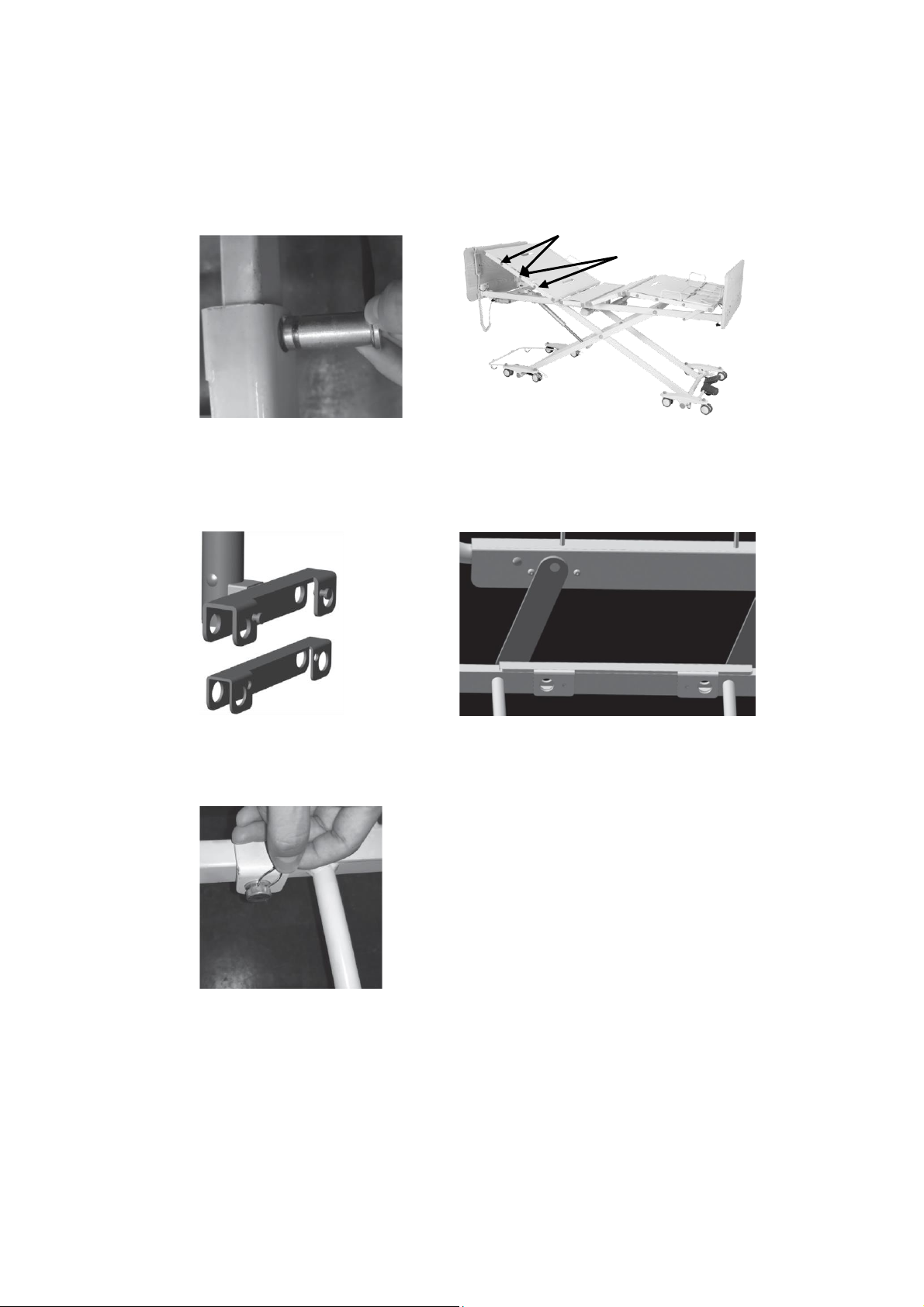
Installing the rails or assist bars
1. Before installing the rails or bars, the bed should be in a flat position.
2. Unclip the metal snap ring and remove the metal pins from the mounting
brackets.
3. Remove cover for the appropriate holes.
4. Slide the U-shaped insert into the assist bar bracket. Place the rail bracket onto
the edge of the bed decking. Align the rail bracket mounting holes with the bed
deck mounting holes.
5. Re-insert the metal pins from the outside edge of the bed through the mounting
holes and secure with snap rings on the inside edge of the bed. Make sure the
snap rings are positioned in the groove of the metal pins.
6. If the bed rail or bar has additional Allen screws, tighten the Allen screws next to
the metal pins.
7. Repeat the same procedure to install the other rail.
Holes for Swing Rail
Holes for Assist Bar
Page 15
14
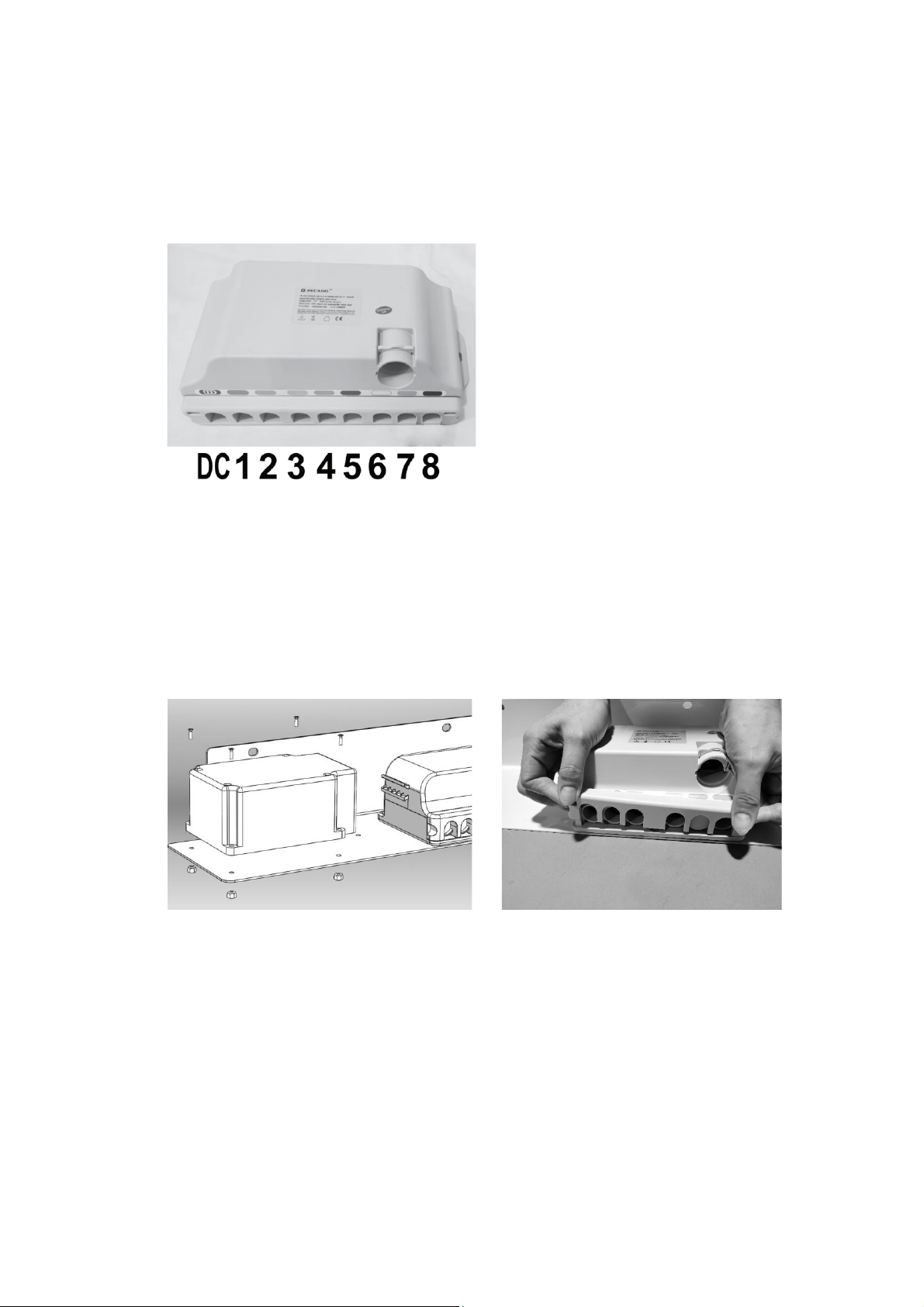
Control box connections
Upon opening the control box, each motor connection port is color coded for ease of
identification.
DC. Battery Backup Port
1. Backrest Motor
2. Knee-break Motor
3. Hi-Lo Motor (Front)
4. Hi-Lo Motor (Rear)
5. Underbed Lighting
6. Spare
7. Staff Control
8. Hand Pendant
Installing battery backup (pre-installed)
1. Switch the power supply off when installing the backup battery.
2. Affix the backup battery with nuts and bolts to the side of the control box, on the
same holding plate.
3. Open the control box locking lid by pressing in the sides and lift it up, to expose
the connection ports.
4. Connect the backup battery cord to the control box. The connection port is
indicated with a battery symbol above.
5. Close the locking lid, there should be an audible click, switch the power supply
back on.
Page 16
15
EQUIPMENT OPERATION
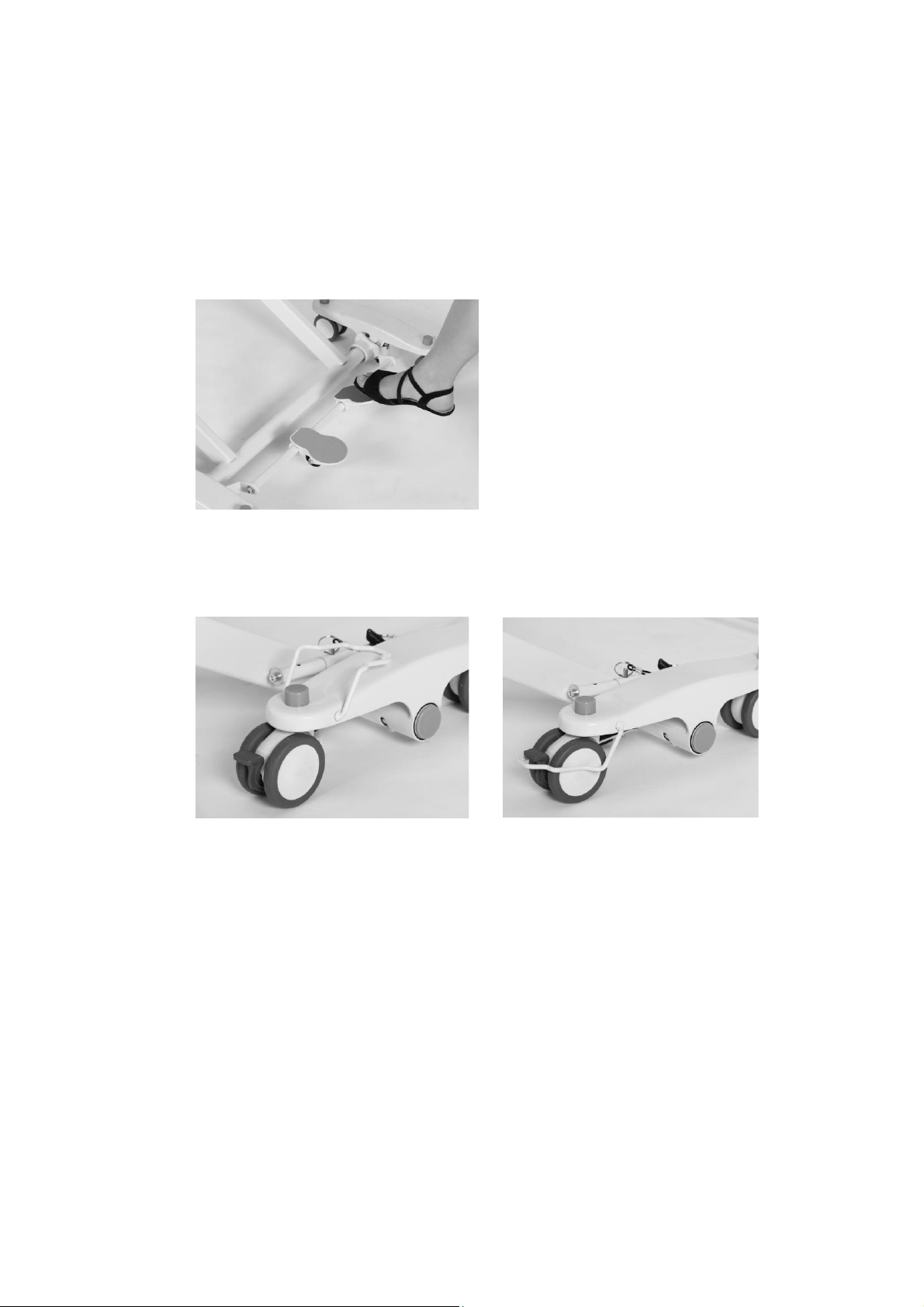
Positioning the Bed
1. To lock the bed, step on the red lever at the rear of the bed.
2. The caster guides on both sides of the head end casters should be lowered to
prevent sideway movements. When lowered, the caster guide should hug around
the caster.
3. To unlock the casters, step on the green lever at the rear of the bed. Lift up the
caster guides on the head end casters to allow free movement.
NOTE: Head end caster must be unlocked when raising and lowering the bed. Head
end caster guide should be lowered onto the caster when bed is in use.
Page 17
16
Extend the Length of the Bed from 80” to 88”
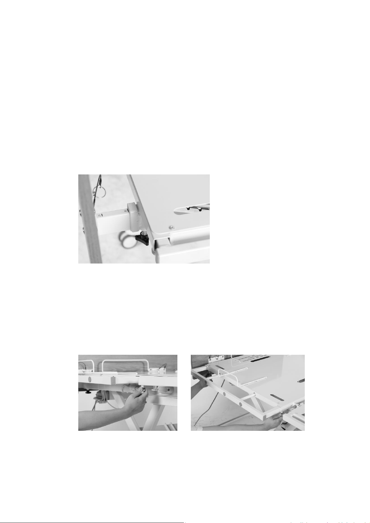
The bed length can be extended by 2” at the head and up to 6" at the foot.
To extend the bed length:
1. Loosen the two black knobs located on the underside of the bed frame securing
the head/foot board brackets. (Refer to Section 3)
2. Pull the head/foot board brackets away from the bed squarely with both hands
until the brackets latch onto the bed frame. The distance is also marked on the
brackets. Tighten the securing knobs once the brackets are extended.
3. Adjust the bed end mattress retention frame to the required position. The
extension length is marked on the bed platform.
Extend the Width of the Bed from 35” to 42” or 48”
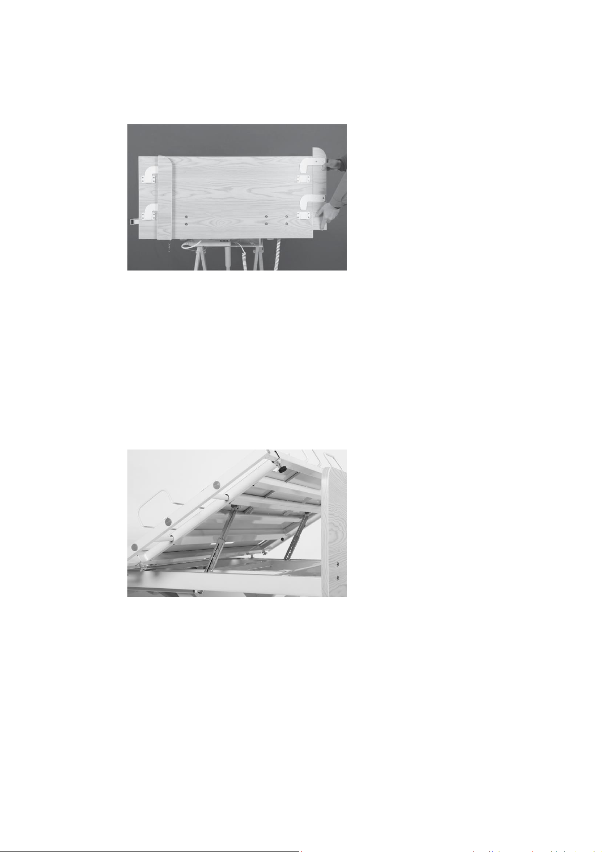
1. Under each deck section there are two springed plungers. Pulled down the
springed plungers and at the same time slide out the extension piece to the
required length. There should be an audible click indicating that the extension
piece is locked in place.
2. Repeat the same procedure on all bed sections and on both sides of the bed.
3. Adjust the mattress retainers accordingly.
Page 18
17
4. To extend the headboard, lift up and flip the extension piece on the back of the
headboard. Reinsert the steel plates into the mounting brackets on the main
headboard.
Adjusting the Extended Heel Lift
1. Grip the end section of the bed platform. Lift up slowly to the preferred height.
Ensure there is an audible click indicating that the deck is locked in place within
the Ratcheting Bracket.
2. To lower the end deck to its original position, lift it up to the highest position and
slowly lay the bed section back down.
Page 19
18
Using the Controller
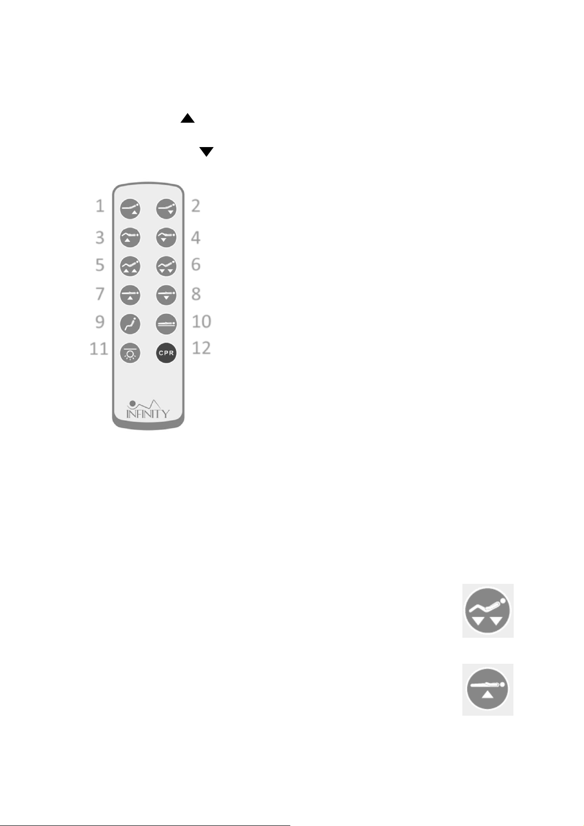
The UP arrow ( ) indicates raising the corresponding parts of the bed.
The DOWN arrow ( ) indicates lowering the corresponding parts of the bed.
1. Use button □1 and □2 to adjust the backrest up or down.
2. Use button □3 and □4 to adjust the kneebreak up or down.
3. Use button □5 and □6 to simultaneously adjust the backrest
and kneebreak up or down (Auto-Contour).
4. Use button □7 and □8 to raise or lower the bed platform.
5. Use button
□
9 to put the bed into chair position.
6. Use button
□
10 to put the bed into flat position.
7. Use button
□
11 to turn on/off the underbed lighting.
8. Use button
□
12 to engage in electronic CPR lowering.
Resetting the Bed
Where a connection fault is identified and rectified, the control system will require a
reset in order to operate again.
1. Press and hold the control button for lowering the backrest and
kneebreak. Continue to hold down the button for 10 seconds after the
mattress platform is completely flat.
2. Press and hold the control button for raising the mattress platfrom.
Continue to hold down the button for 10 seconds after the mattress
platform reaches the highest position.
1
2
3
4 5 6
7 8 9
10
12
11
Page 20
19
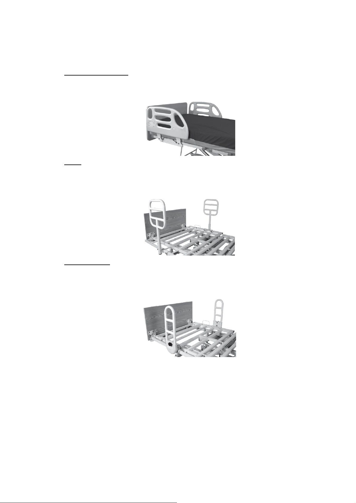
Operating the bed rails
Composite Swing Rail
Raise Bed Rail: Pull the bed rail upwards until the rail is securely locked in place.
Lower Bed Rail: Press the release button, slowly lower the rail to its lowest position.
Q-Bar
Parallel/ Lift up and rotate the bar until it is parallel or perpendicular to the
Perpendicular bed edge. Lower the bar and ensure it is securely locked in place.
Alignment:
Pivot Assist Bar
Raise Assist Bar: Pull the bar upwards until it is securely locked in place. Ensure the
release button is engaged.
Lower Assist Bar: Pull the release knob and slowly lower the bar to its lowest position.
Page 21

20
TROUBLESHOOTING GUIDE
SYMPTOMS
POSSIBLE FAULTS
POSSIBLE SOLUTIONS
Bed idle when hand pendant
buttons are pressed.
Adjustment may be at the
maximum or minimum
position
Power cord not connected or
damaged
Hand pendant or actuator
connectors are loose
Load is too heavy
Control system requiring a
reset
Check if other buttons are
working.
Ensure the power cord is
properly connected to the
electrical socket and the bed.
Ensure tight connection of all
connectors to control box.
Ensure the load weight is
within the designated
capacity. Reduce the load.
*Reset the electronic system
using the hand pendant.
Casters/Brakes noisy or stiff.
Debris or fluff in bearings
Replace casters.
Noisy or dry sound from
pivots.
Needs lubrication
Lubricate your bed.
Unusual noise from actuator.
Actuator is worn or damaged
or spindle is bent
Replace the actuator. Contact
your supplier.
Head/footboard unstable.
Head/footboard frame not
tightly secured.
Refer to Equipment Assembly
* Refer to page 18 of this the manual for electronics reset procedures.
If problems persist following the above remedial procedures, please contact your
dealer or the manufacturer.
Page 22

21
LIMITED WARRANTY
The Manufacturer warrants to the original user (Customer) all products manufactured by the
Manufacturer to be free from defects in material and workmanship under normal use and
service for a period as specified below. If such a defect appears and Customer has given
immediate written notification of same, the Manufacturer shall replace or repair such part at
the Manufacturers option. The Manufacturer will require the return of the defective part to
establish the claim. The Manufacturer’s obligation under this warranty shall be limited to said
replacement and/or repair. Installation and freight costs for replaced or repaired items remain
the responsibility of the Customer. This warranty does not cover failure due to negligence,
accident, deliberate abuse, nor improper installation and/or maintenance. Modifications made
to products (including modifications without the expressed written consent of the
Manufacturer) shall void this warranty in its entirety. NO FURTHER WARRANTIES, EXPRESSED OR
IMPLIED, INCLUDING, BUT NOT LIMITED TO, WARRANTIES OF MERCHANTABILITY OR FITNESS
FOR A PARTICULAR PURPOSE NOT SPECIFIED HEREIN, ARE MADE BY THE MANUFACTURER, AND
THIS WARRANTY SETS FORTH THE FULL EXTENT OF THE LIABILITY ARISING FROM THE
MANUFACTURE, USE OR SALE OF THE PRODUCTS AND MATERIALS SOLD HEREUNDER. No
allowances will be made for delays or loss of profit, nor for any other special, indirect or
consequential damages or injuries, whether based on tort or contract.
Applicable warranty periods commencing from date of shipment from ES are as follows:
Welds ………………………………………………………......................... 15 years
Electrical & Mechanical components ….………………………….…. 3 years
All other components …………………………………………….………….. 1 year
Page 23

22
APPENDIX – SERVICE RECORD
DATE
PERFORMED BY
CONDITION REPORT
Page 24

23
DATE
PERFORMED BY
CONDITION REPORT
 Loading...