

Emerald Spa Lite Leader, SS-1D, SS-3D, DS-2, DS-4 Owner's Manual

Owner's Manual
copyright 2002
Emerald Spa Corporation
(rev. 5/02) All Rights Reserved
Introduction
Congratulations on your purchase of the finest whirlpool spa on the market today. Emerald Spa
Corporation welcomes you to the Emerald Whirlpool Spa Life-style! We are confident that this purchase
will fulfill all your comfort, therapy and relaxation needs.
With proper care, your spa will provide many years of comfort and pleasure. Please take the time to
read all of the instructions before you install your Emerald or Cygnus Series Spa. This Owner's Manual
will help you understand all the features of your spa and ensure that you get the most from your investment.
Remember, your beautiful new spa is a powerful appliance! You owe it to yourself, your family and
friends, to make sure that the spa is installed correctly and safely.
This manual explains safety precautions, installation instructions, operating directions, and maintenance
procedures. If you have questions after reading this manual, please call your Emerald Spa Service
Representative at 1-800-766-7727.
Read and understand all safety, installation, operating instructions and all warnings
and cautions before adding water or attaching electrical power.
Information on Your Spa
Spa Model:
Power Pack Model:
Serial #:
Warnings,
Cautions,
and Notes
Throughout this manual, various Warnings, Cautions, and Notes will appear in the left margin or at the
beginning of the text associated with the Warning, Caution, or Note. These comments range in importance
from helpful hints to situations where the possibility of personal injury exists. Please take the time to read
and understand them. The pictures and drawings may not reflect product changes that occurred after the
printing of this manual.
Warnings, Cautions, and Notes appear as follows:
WARNING:
Indicates a situation in which
personal injury may occur.
CAUTION:
Indicates a situation in which
damage to equipment or mate-
rial may occur.
NOTE:
Provides helpful information for
proper operation of your Emerald whirl-
pool spa.
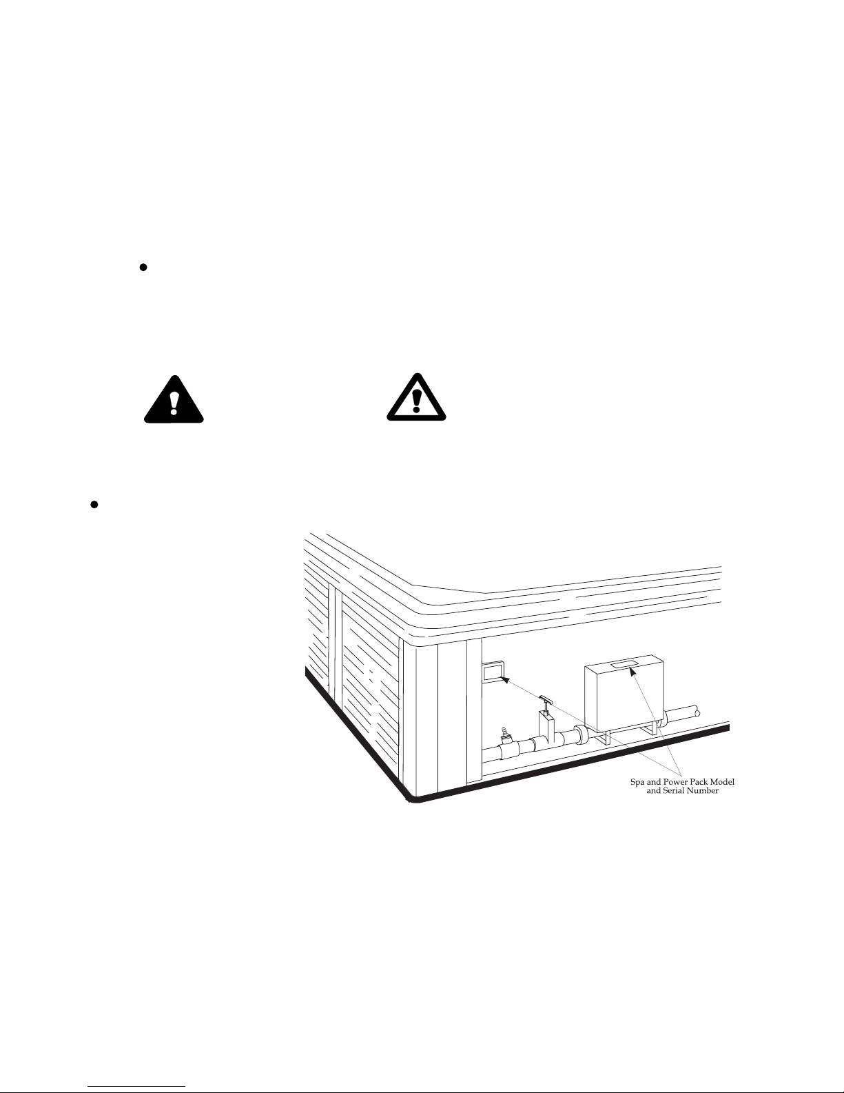
Model and Serial
Number Locations
Refer to the illustration below to locate and record the model number and serial number of both your Spa and
Spa Power Pack.
SAVE THESE INSTRUCTIONS

Table of Contents
INTRODUCTION ....................................................................................2
IMPORTANT SAFETY INSTRUCTIONS ...................................................4-5
IMPORTANT USER SAFETY INSTRUCTIONS .......................................6-7
SPA LOCATION .........................................................................................8
INSTALLATION INSTRUCTIONS ...............................................................9
General Procedures ......................................................................9
240V Systems.................................................................................10-12
FEATURES AND CONTROLS......................................................................13
Spa At-A-Glance................................................................................... 13
Equipment Compartment...................................................................14
Power Pack...................................................................................15-17
Spa Side Control Panels.................................................................18-30
Lite Leader......................................................................18-19
SS-1D.................................................................................20-21
SS-3D.............................................................................................22-23
DS-2.........................................................................................24-26
DS-4.....................................................................................27-32
In-spa Features ............................................................................................33-36
STARTING AND USING YOUR SPA...................................................................37
Installation of Filter Element....................................................................37
Proper Water Level...............................................................................38
Bleeding Air for one and two pump systems..................................38
Testing the Ground Fault Circuit Interrupter (GFCI)......................39
Pump Priming........................................................................................39-40
Setting the Thermostat............................................................................41
SPA WATER CHEMISTRY.......................................................................................42
Chemical Safety Tips.............................................................................42
Spa Capacity.............................................................................................42
pH Control.............................................................................................43
Disinfecting Your Spa............................................................................44
Ozone Generator....................................................................................45
Other Water Chemistry Considerations.......................................................45
MAINTAINING YOUR SPA......................................................................................46
Draining the Water....................................................................................46
Cleaning the Spa Shell..............................................................................47
Cleaning the Filter....................................................................................47
Space Saver II Filtration System.............................................................48
Relamping the Underwater Light............................................................48
Standby Mode...........................................................................................48
Winterizing Your Spa..............................................................................49
The Spa Cabinet.................................................................................49
TROUBLESHOOTING.......................................................................................50-54
Lite Leader, SS-1D & SS-3D................................................................50-51
DS-2 & DS-4....................................................................................52-54
ELECTRICAL SCHEMATICS .......................................................................55-59
Lite Leader.........................................................................................................55
SS-1D...............................................................................................................56
SS-3D.............................................................................................................57
DS-2..................................................................................................................58
DS-4..................................................................................................................59

IMPORTANT SAFETY
INSTRUCTIONS
When installing and using this electrical equipment, basic safety precautions should always be adhered to,
including the following:
1. READ AND FOLLOW ALL INSTRUCTIONS.
2. WARNING: To Reduce the risk of injury, do not permit children to use this product unless they are
closely supervised at all times.
3. A wire connector is provided on this unit to connect a minimum No. 8 AWG (8.4mm2) solid copper
conductor between this unit and any metal equipment, metal enclosures of electrical equipment,
metal siding, metal sliding doors, metal rails, metal water pipe, or conduit within 5 feet (1.5m) of the
unit.
4. DANGER: Risk of accidental drowning. Extreme caution must be exercised to prevent
unauthorized access by children. To avoid accidents, ensure that children cannot use this spa
unless they are supervised at all times.
5. DANGER: Risk of injury. The suction fittings in this spa are sized to match the specific water flow
created by the pump. Should the need arise to replace the suction fittings or the pump, be sure that
the flow rates are compatible. Never operate your spa if the suction fittings are broken or missing.
Never replace a suction fitting with one rated less than the flow rate marked on the original suction
fitting.
6. DANGER: Risk of electric shock. Install at least 5 feet (1.5m) from all metal surfaces. As an
alternative, a spa may be installed within 5 feet of metal surfaces if each metal surface is
permanently connected by a minimum No. 8 AWG (8.4mm2) solid copper conductor to the wire
connector on the terminal box that is provided for this purpose.
7. DANGER: Risk of electric shock. Do not permit any electric appliance, such as a light, telephone,
radio, or television within 5 feet (1.5m) of a spa.
General
4
Emerald Whirlpool Spa Owner's Manual
SAVE THESE INSTRUCTIONS

IMPORTANT SAFETY
INSTRUCTIONS
When installing and using this electrical equipment, basic safety precautions should always be adhered to,
including the following:
1. READ AND FOLLOW ALL INSTRUCTIONS.
2. Read and follow all General Safety Instructions provided on pg. 4.
3. A terminal marked "GROUND" is provided within the motor control enclosure. To reduce the risk
of electrical shock, connect this terminal to the grounding terminal of the electric supply panel with
a continuous green insulated copper wire equivalent in size to the circuit conductors supplying this
equipment.
4. This equipment must be provided with a ground fault circuit interrupter located in the power
supply panel as installed by an electrician. Before each use of your spa, with the power turned on,
push the test button. A red indicator should appear. Push the reset button, and the red indicator
should disappear. IF THE INTERRUPTER FAILS TO OPERATE IN THIS MANNER, THERE IS A
GROUND CURRENT FLOWING, INDICATING THE POSSIBILITY OF AN ELECTRIC SHOCK.
Shut off the power to the spa until the source of the breakdown has been identified and
corrected.
5. The electrical service panel should be equipped with a 50-amp GFCI overcurrent protective device.
6. The minimum supply conductor capacity is 50 Amp and should be sized as follows:
No. 6 AWG, or No. 8 AWG 75o C.
7. The electrical supply for the spa must include a suitably rated switch or circuit breaker to open all
ungrounded supply conductors, to comply with section 422-20 of the National Electrical Code,
ANSI/NFPA 70-1999. The disconnecting means must be readily accessible to the spa occupant but
must not be within 5 feet of the spa.
240V Hard Wired
Connected
Systems
SAVE THESE INSTRUCTIONS
5
Important Safety Instructions

IMPORTANT USER SAFETY
INSTRUCTIONS
When using this spa, basic safety precautions should always be followed.
WARNING:
As a spa owner, you should always review these instructions with first time or occasional users of the spa.
Remember, they may not be aware of the possible risks associated with spa water temperature.
1. READ AND FOLLOW ALL INSTRUCTIONS.
2. WARNING: TO REDUCE THE RISK OF INJURY, do not permit children to use this product unless
they are closely supervised at all times.
3. DANGER: RISK OF ACCIDENTAL DROWNING. Extreme caution must be exercised to prevent
unauthorized access by children. To avoid accidents, ensure that children cannot use the spa unless
they are supervised at all times.
4. WARNING: TO REDUCE THE RISK OF INJURY, the water in a spa should never exceed 104o F
[40o C]. Water temperatures between 100o F [38o C] and 104o F [40o C] are considered safe for a
healthy adult for a 10 to 15 minute time period. Lower water temperatures are recommended for
extended use [exceeding 10-15 minutes] and for young children.
5. Since excessive water temperatures have a high potential for causing fetal damage during the early
months of pregnancy, pregnant or possibly pregnant women should limit spa water temperatures
to 100o F [38o C].
6. Before entering a spa, the user should measure the water temperature with an accurate thermometer such as a medical thermometer, since the tolerance of temperature regulating devices vary.
7. The use of alcohol, drugs, or medication before or during spa use may lead to unconsciousness with
the possibility of drowning.
To Reduce the
Risk of Injury
6
Emerald Whirlpool Spa Owner's Manual
SAVE THESE INSTRUCTIONS

IMPORTANT USER SAFETY
INSTRUCTIONS (Continued)
8. Persons suffering from obesity or with a medical history of heart disease, low or high blood
pressure, circulatory system problems, or diabetes should consult a physician before using a spa.
9. Persons using medication should consult a physician before using a spa, since some medications
may induce drowsiness while other medications may affect heart rate, blood pressure and
circulation.
10. Extended use of your spa in water temperatures between 100o F and 104o F may cause
HYPERTHERMIA (elevated body temperature). Hyperthermia occurs when the internal
temperature of the body reaches a level several degrees above the normal body temperature of
98.6o F. The symptoms include dizziness, fainting, drowsiness, lethargy, and an increase in the
internal temperature of the body. The effects of hyperthermia include (1) unawareness of impending
hazard, (2) failure to perceive heat, (3) failure to recognize the need to exit the spa, (4) physical
inability to exit the spa, (5) fetal damage in pregnant women, and (6) unconsciousness, resulting in
a danger of drowning.
11. WARNING: The use of alcohol, drugs, or medication can greatly increase the risk of fatal
hyperthermia in spas.
12. During Winter months where the temperature is consistently below freezing, check your spa
periodically to assure that it is operating correctly and that the power to the spa has not been
interrupted as to assure that the water lines are not in danger of feezing.
13. Do not use your spa alone.
14. Make sure that the following emergency telephone numbers are listed at the nearest telephone:
physician, hospital, ambulance, and police.
15. Have at least one person in the family learn CPR (cardio-pulminary resuscitation). It could save a
life!
SAVE THESE INSTRUCTIONS
7
Important User Safety Instructions

SPA LOCATION
Outdoor Considerations
Indoor Considerations
There are many things to consider prior to locating your spa. The following lists cover some of the more common factors involved in choosing the ideal location.
Local fencing and enclosure codes.
Local electrical and plumbing codes.
The view from your house.
Your ability to supervise the spa.
Wind direction and exposure to sunlight.
Location relative to trees (falling leaves and shade).
Dressing and bathroom location.
Storage area for maintenance equipment and chemicals (storing chemicals inside your spa cabinet
will void the warranty).
Landscaping and evening lighting.
Spa must be placed on a flat, level surface.
Water is heavy. If a spa is placed on flooring or decking, be sure the structure is strong enough to
support the added weight.
Walls, ceiling, flooring, and woodwork must be able to withstand high humidity.
You may need cross-ventilation fans or oversized dehumidifiers (or both) to remove excess humidity.
Spa chemicals in the air may corrode certain metals in your home.
Floor drains are needed to carry off water splashed from the spa.
Recessed spas must be positioned to permit servicing from above or below floor.
Water is heavy. Be sure the flooring or decking is strong enough to support the added weight.
Due to the many precautions that must be taken to avoid damage to the surrounding environment from
humidity and water inherent with spa use, it is usually prudent to avoid a second story location that
may be above finished living space.
Outdoor Considerations
Indoor Considerations
✓✓
✓✓
✓
✓✓
✓✓
✓
✓✓
✓✓
✓
✓✓
✓✓
✓
✓✓
✓✓
✓
✓✓
✓✓
✓
✓✓
✓✓
✓
✓✓
✓✓
✓
✓✓
✓✓
✓
✓✓
✓✓
✓
✓✓
✓✓
✓
✓✓
✓✓
✓
✓✓
✓✓
✓
✓✓
✓✓
✓
✓✓
✓✓
✓
✓✓
✓✓
✓
✓✓
✓✓
✓
✓✓
✓✓
✓
8
Emerald Whirlpool Spa Owner's Manual
INSTALLATION INSTRUCTIONS
General Procedures
240V Systems
This section covers the installation of your spa. All electrical steps must be performed by a licensed electrician.
The spa must be connected to a proper power supply and meet all National Electrical Code (N.E.C.) and local
code requirements. The connection must include the conductors necessary for operation and bonding, as
required by N.E.C.
1. Remove the spa from its shipping container and retain all safety, operation, and warranty information.
2. Position the spa on a flat, level surface such as concrete, or a wood deck which provides adequate
drainage.
3. Position the spa at least 5 feet from all metal surfaces unless each metal surface is permanently
connected to a bonding wire, as indicated in step 4.
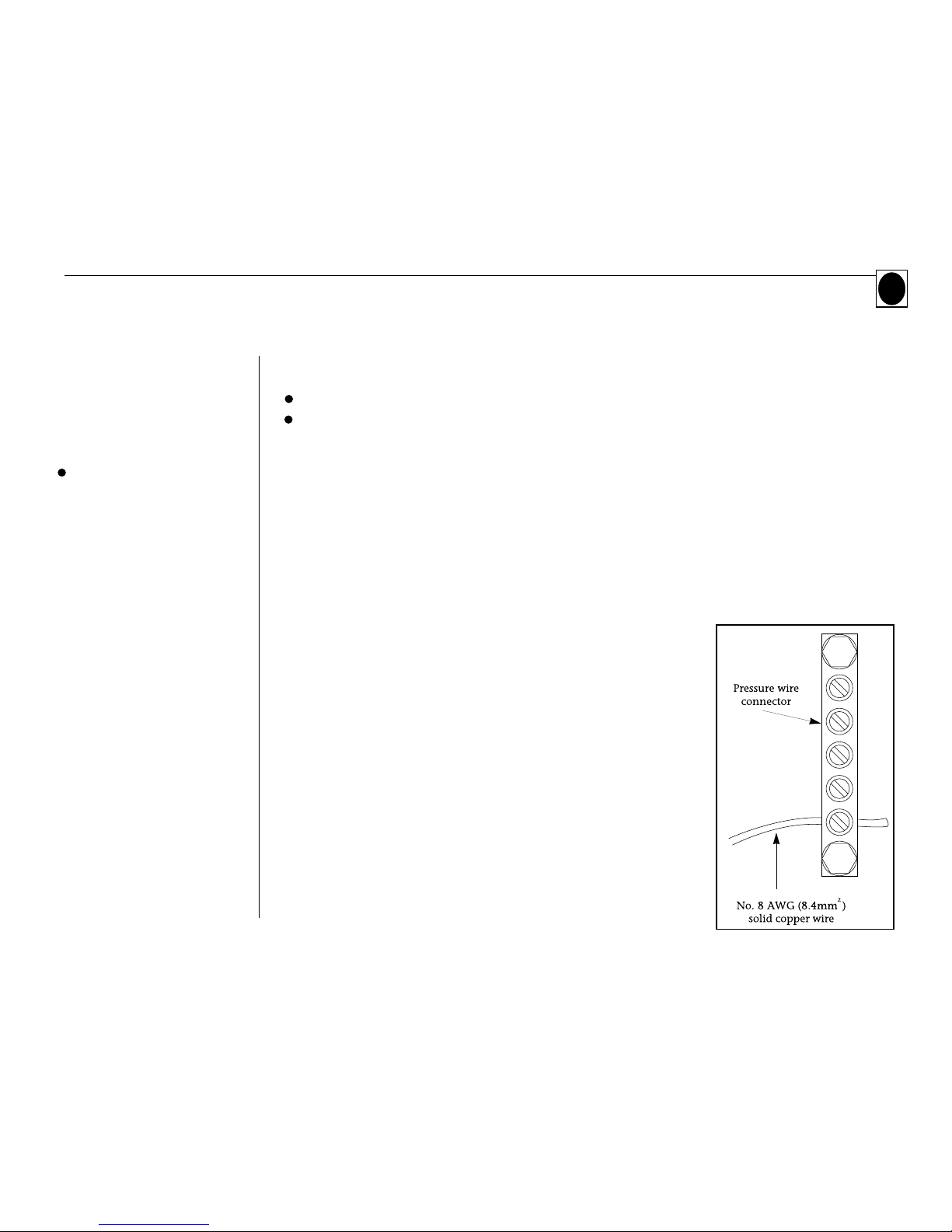
4. The spa may be installed within 5 feet of metal surfaces as follows:
- Installation must be in accordance with Article 680-42 of the
National Electrical Code, ANSI/NFPA 70-1999.
- Each metal surface must be permanently connected to a bonding
wire which is attached to a pressure wire connector provided for
that purpose.
- The pressure wire connector is located on the equipment system
control enclosure.
- The bonding wire must be at least No. 8 AWG (8.4 mm2) solid
copper wire.
- The bonding wire must be attached to the pressure wire connector
and all metal equipment, metal enclosures of electrical equipment,
metal water pipe, or conduit within 5 feet of the spa.
Located on the side of the spa pack box
9
Installation Instructions
General Procedures
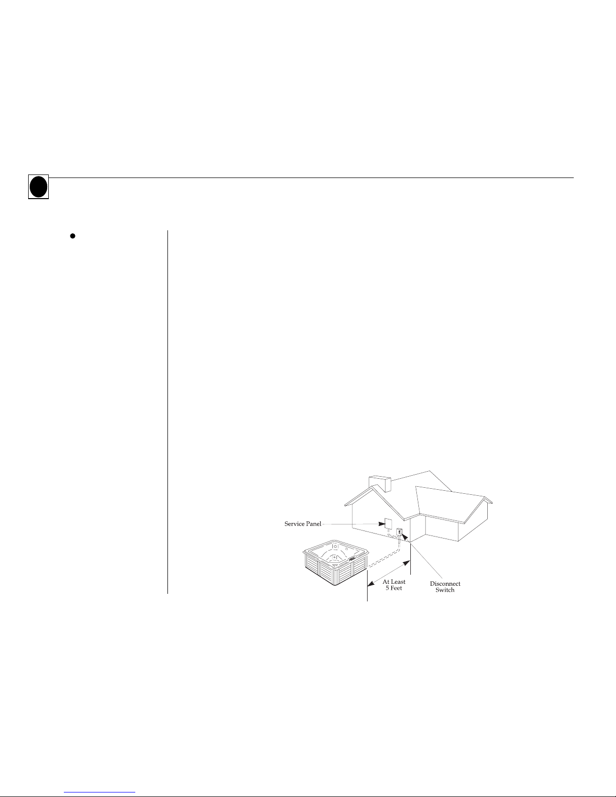
1. Install a 50-amp, GFCI overcurrent protective device in the electrical service panel.
2. The electrical supply for the spa must include a suitable rated switch or circuit breaker to shut off
the power supply (to comply with section 422-20 of the National Electrical Code, ANSI/NFPA 70-
1999). This disconnecting means must be readily accessible to the spa occupant, but must not be
within 5 feet of the spa. (see diagram below)
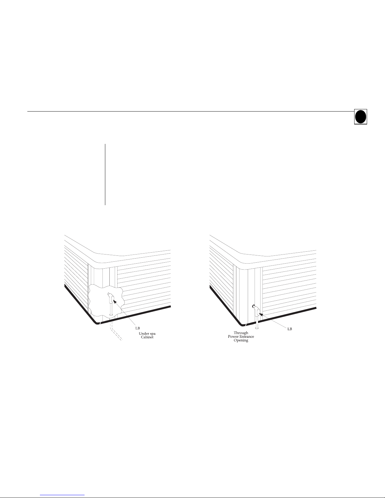
3. With the spa placed in its final location, power can be routed in two ways:
Under the spa cabinet- See figure 1 on pg. 11
- Determine placement of hole in floor so that conduit may enter between the spa shell and the
wooden cabinet.
- Move the spa to allow working room. Cut off the conduit above the floor surface.
- Use an LB on the conduit to permit wire pulling if required.
Through a power entrance opening drilled by an
electrician - See figure 2 on pg. 11
- Move the spa to allow working room. Use nonmetallic conduit and fittings. Cut off the conduit
above the floor surface to permit the installation of an LB at the power entrance opening height.
240V Systems
(Lite Leader 240V,
SS-1D, SS-3D,
DS-2, DS-4)
10
Emerald Whirlpool Spa Owner's Manual
4. Pull 4 copper current carrying conductors (one each: black, red, white, green). Use either No. 6 AWG
60o C, No. 8 AWG 75o C, or No. 8 AWG 90o C wire, if spa is 100 feet or less away from its power supply.
Note: the ground must be equal to or larger than the largest power conductor.
5. Reposition the spa at its final location and route the flexible conduit.
6. Using a 1" conduit connector at the end of the flexible conduit, route wires through an entrance hole cut
by your electrician in the control enclosure, and attach the conduit connector to the control enclosure.
240V Systems
[Continued]
Figure 1 Figure 2
Installation Instructions
11
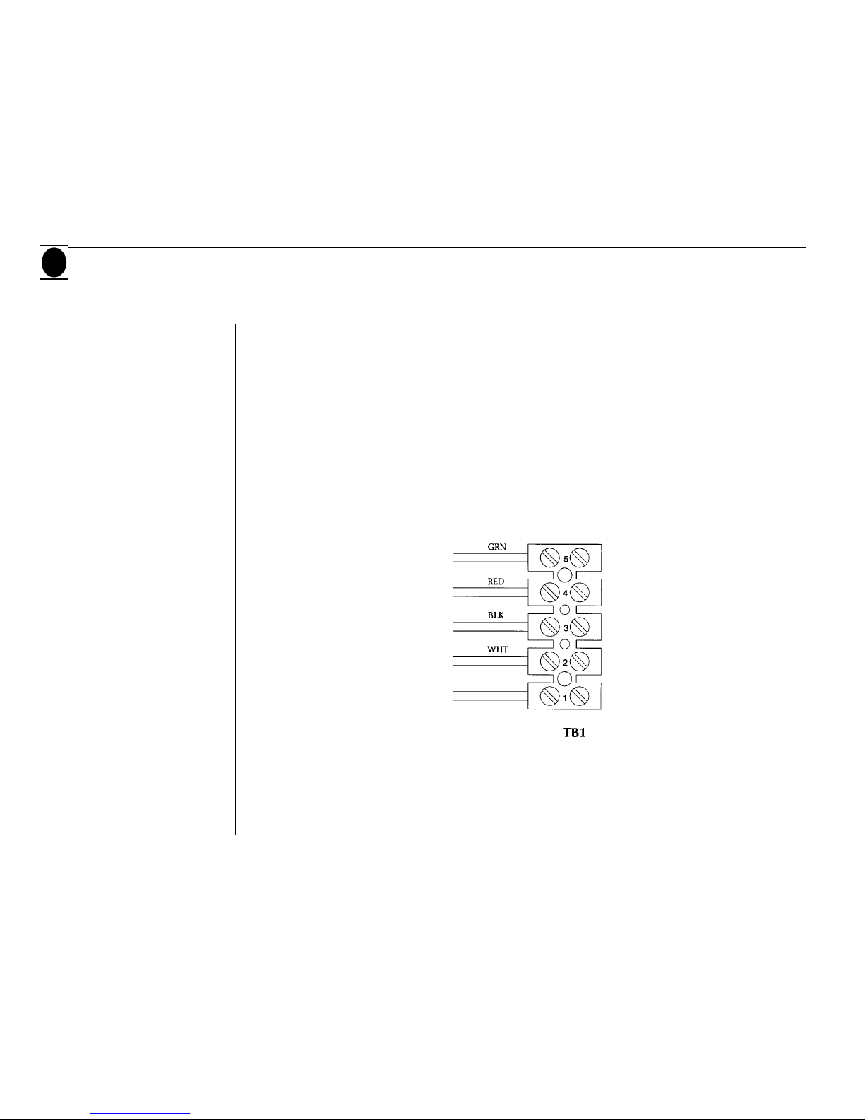
7. Attach power wires to the terminal block. See 240V wiring diagram inside the control enclosure
cover. Attach the wires as follows:
- White wire to terminal #2
- Black wire to terminal #3
- Red wire to terminal #4
- Green wire to terminal #5
8. Complete the conductor connections at the power supply panel.
9. Do not turn power on until instructed to do so in the "Starting and Using Your Spa" section.
240-Volt Power Input
Note:
Consult the Wiring Diagram on Page 53 for 240 Volt to 120 Volt conversion on
the Lite Leader System Only.
Emerald Whirlpool Spa Owner's Manual
12
Spa At-A-Glance
Spa At-A-Glance
Equipment Compartment
Power Pack
Spa Side Control
In-Spa Features
1 - Pump System 2 - Pump System
FEATURES AND CONTROLS
Your Emerald Whirlpool spa may be equipped with a variety of user controls and optional features. This
section locates and describes each. Please take the time to recognize and understand the functions of these
components and controls.
Spa At-A-Glance provides a pictorial overview of key user components.
Features and Controls
13
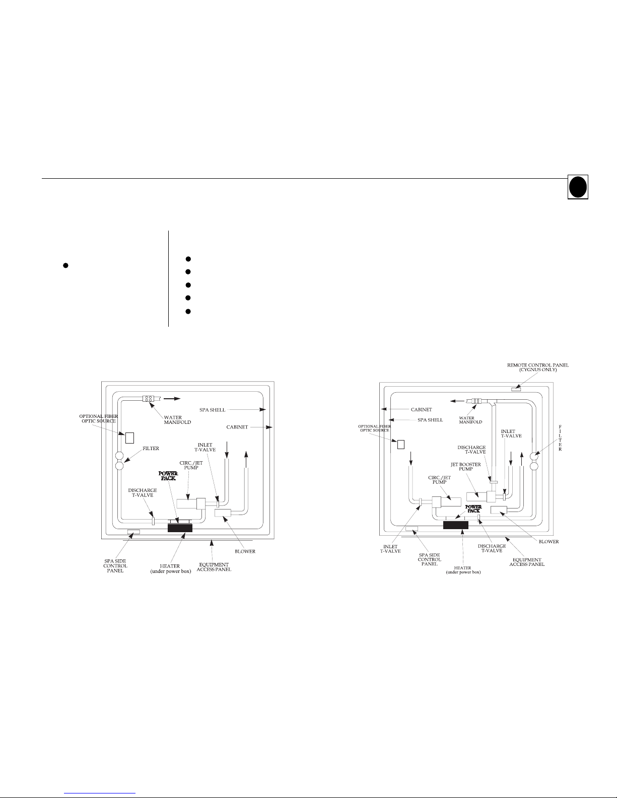
(These diagrams represent generic one pump and two pump systems. They are not intended to represent any specific model.)
The equipment compartment houses the "nerve center" of the spa and includes the following system components.
Pump(s)
Emerald Spas have different pump systems, depending on the spa model. Emerald Base, Classic and Special
Edition spas have a two-speed (circulation/jets) pump and provide:
- Filtration, circulation and heat on low speed.
- Hydrotherapy jet action on high speed for 120V. For 240V, the spa will also heat in high speed.
The Emerald Elite and Cygnus series have a two pump system which uses an additional booster pump to
enhance jet action.
Blower
Emerald Classic, Elite, Special Edition and Cygnus spas include a blower to provide bubble therapy and an
enhanced force of air to the water jets called High Performance-Jet Select.
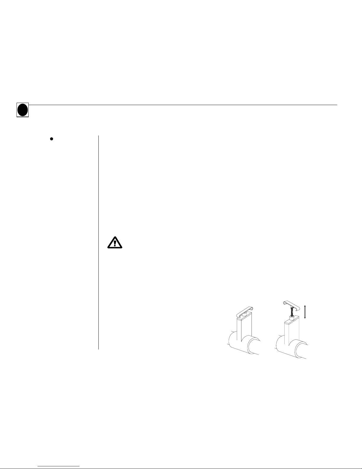
Caution:
T-valves must be open when spa is in use. See Fig. 1.
T-valves must be in closed position before any plumbing is disassembled for service. See Fig. 2.
T-valves
All one-pump systems have two T-valves, located in the water circulation lines on either side of the power pack.
Some models have two pumps, which include two additional T-valves located on either side of the booster pump.
To operate T-Valve:
- To close, temporarily remove security clip and push
T-handle down.
- To open, pull T-handle up and secure
with security clip.
Equipment
Compartment
14
Emerald Whirlpool Spa Owner's Manual
Fig. 2 Fig. 1
Lock Unlock
Open,
Detent (1 1/2"
valve only)
Closed
Open, Detent
Position
Closed, Locked
Position
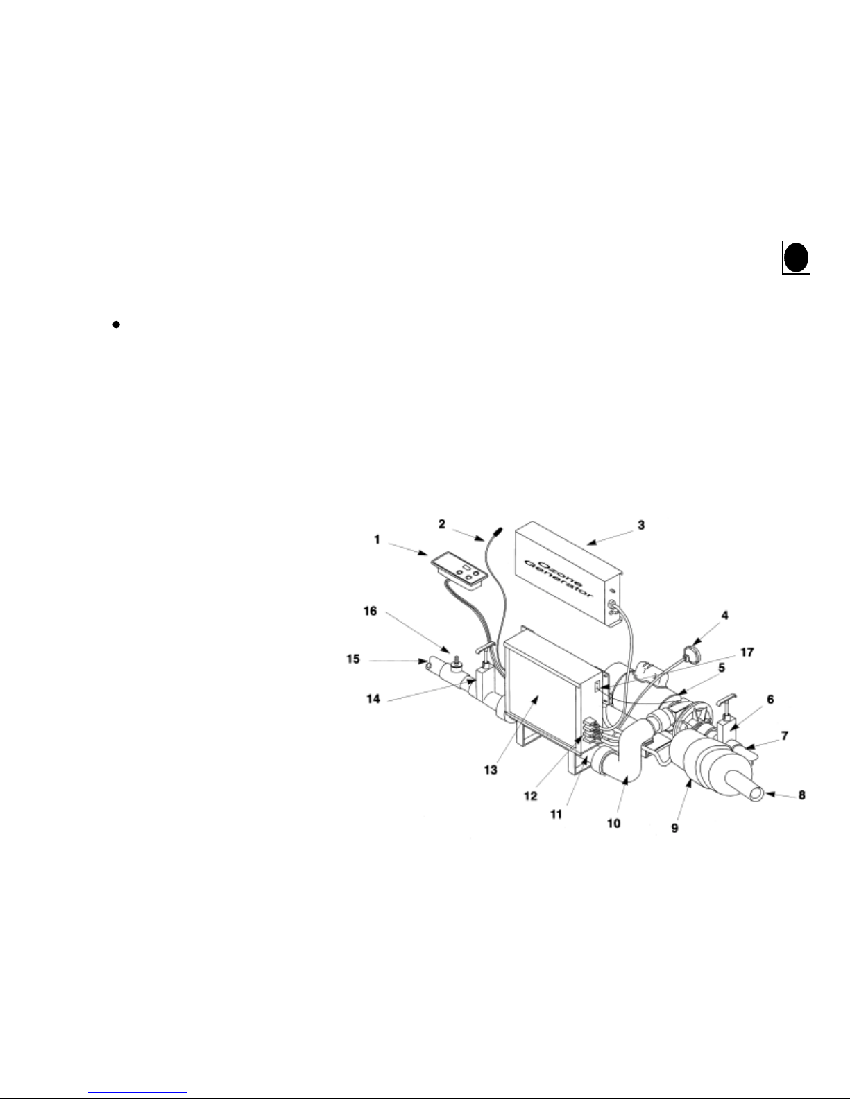
One-Pump System
Below is a general description for the one pump system of the Lite Leader,
SS-1D, and SS-3D used in your Emerald spa.
1. control panel - (SS-3D shown) 10. connector plumbing elbow
2. temperature sensor 11. heater
3. ozone generator (optional) 12. control outputs
4. light 13. power pack
5. 2-speed circulation/jets pump 14. water outlet T-valve
6. water inlet T-valve 15. water outlet line to spa
7. water inlet line from spa 16. ozone tee
8. air line from blower to spa 17. grounding wire
(not on Base Models)
9. air blower
(not on Base Models)
Power Pack
This diagram represents a generic one pump
system. It is not intended to represent any
specific model.
Features and Controls
15
Power Pack
(continued)
This diagram represents a generic two pump
system. It is not intended to represent any
specific model.
16
Emerald Whirlpool Spa Owner's Manual
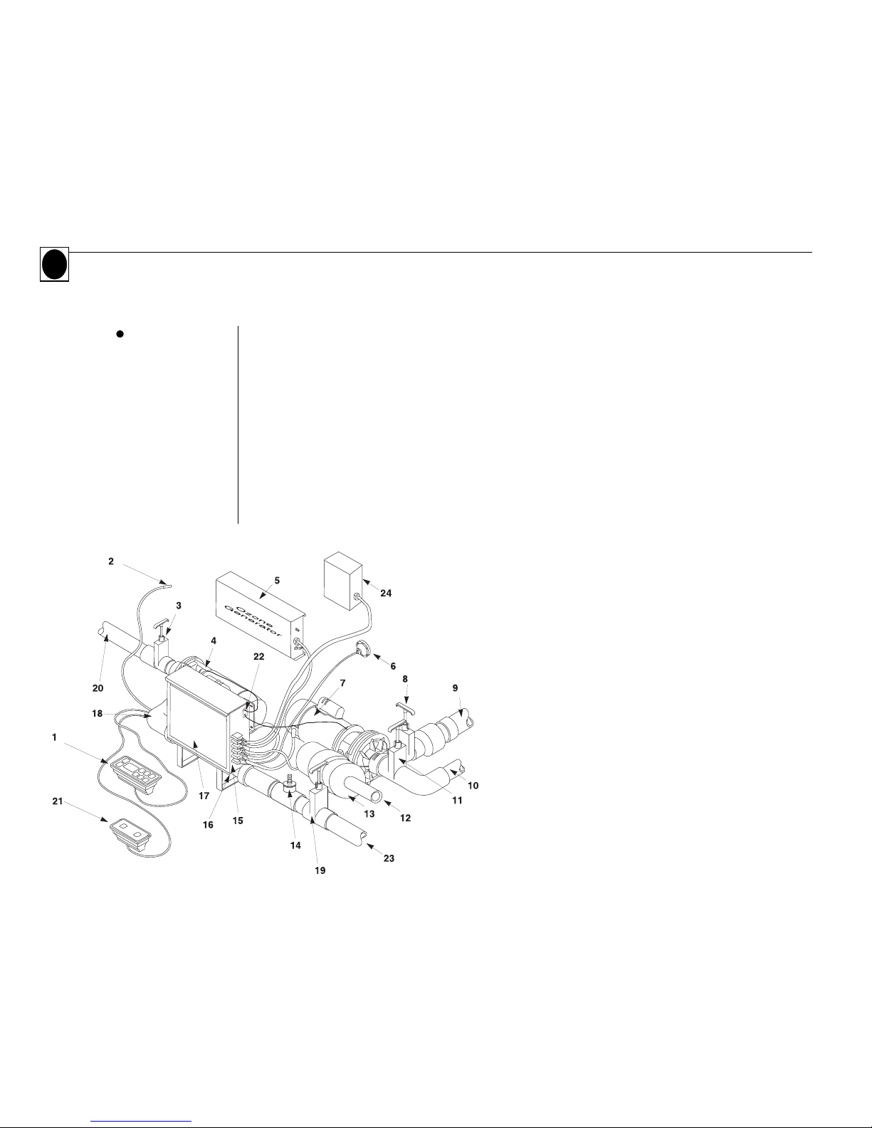
Two-Pump System
All Emerald Elite and Cygnus Series models use a two pump system. The following is a general
description of this system. (This also is a generic model of the 1409 w/DS-2 minus booster pump)
1. control panel - (DS-4 shown) 11. water inlet T-valve - pump 2
2. temperature sensor 12. air line from blower to spa
3. water inlet T-valve - pump 1 13. air blower
4. 2-speed circulation/jets pump 14. ozone tee
5. ozone generator (optional) 15. control outputs
6. light 16. heater
7. booster pump - pump 2 17. power pack
8. water outlet T-valve - pump 2 18. connector plumbing elbow
9. water outlet line to manifold 19. water outlet T-valve - pump 1
10. water inlet line from spa-pump 2 20. water inlet line from spa - pump 1
21. Auxillory control panel - (DS-4 only)
22. grounding bar
23. water outlet line to spa
24. fiber optic source (optional)

Lite Leader SS-1D SS-3D DS-2 DS-4
17
Features and Controls
The Features of each Power Pack are Summarized in the Following Chart:
Pump
Heater
Blower
Light
Control Panel
Ozonator (optional) 120V
Voltage Requirement
Temperature Adjustment
Automatic Time Outs
Preset Filter Cycles
Programmable Filter Cycles
Sensor Failure Detection
Flow Switch Error Detection
Freeze Protection
High Limit Protection with Reset
Heater/Status Indicator
Night Vision Backlight
Continuous Digital H2O Temperature Display
Digital Time Display
Icon Representation of Functions
Digital Operational Status Display (stnd. & econ.)
Digital Diagnostic Display
Automatic Filtration
Automatic Air Injector Purge
Automatic Clean-Up Cycle
Temperature Lock
Panel Lock
Battery Back-Up Program Saver
Remote Control Panel (Option)
High Performance Jet Select
Standby Mode (Pump disable)
Optional Freeze Sensor Input
Fiber Optic Lighting Capable
4.8 hp, 2speed
5.5KW
No
Yes
Digital
Ready
240V
Keypad
Yes
Yes
Yes:Topside
Yes
Yes
Yes
Yes
Yes
No
Yes
No
No
No
Yes
Yes
No
No
No
No
No
Yes
No
No
Yes
No
4.8 hp, 2speed
5.5KW
Yes
Yes
Digital
Ready
240V
Keypad
Yes
Yes
Yes:Topside
Yes
Yes
Yes
Yes
Yes
No
Yes
No
No
No
Yes
Yes
Yes
No
No
No
No
Yes
Yes
No
Yes
No
(1) 3.65hp & (1) 3.5hp
5.5KW
Yes
Yes
Digital
Ready
240V
Keypad
Yes
Yes
Yes:Topside
Yes
Yes
Yes
Yes
Yes
Yes
Yes
Yes
Yes
Yes
Yes
Yes
Yes
Yes
Yes
Yes
Yes
Yes
Yes
Yes
Yes
Yes
1.5 hp, 2speed
1.0/4.0KW
No
Yes
Digital
Ready
240V(120v opt.)
Keypad
Yes
Yes
Yes
Yes
Yes
Yes
Yes
Yes
No
Yes
No
No
No
Yes
Yes
No
No
No
No
No
No
No
No
No
No
(1) 3.65hp & (1) 2hp
5.5KW
Yes
Yes
Digital
Ready
240V
Keypad
Yes
Yes
Yes:Topside
Yes
Yes
Yes
Yes
Yes
No
Yes
No
No
Yes
Yes
Yes
Yes
Yes
No
No
Yes
Yes
Yes
Yes
Yes
Yes
Spa Side Control
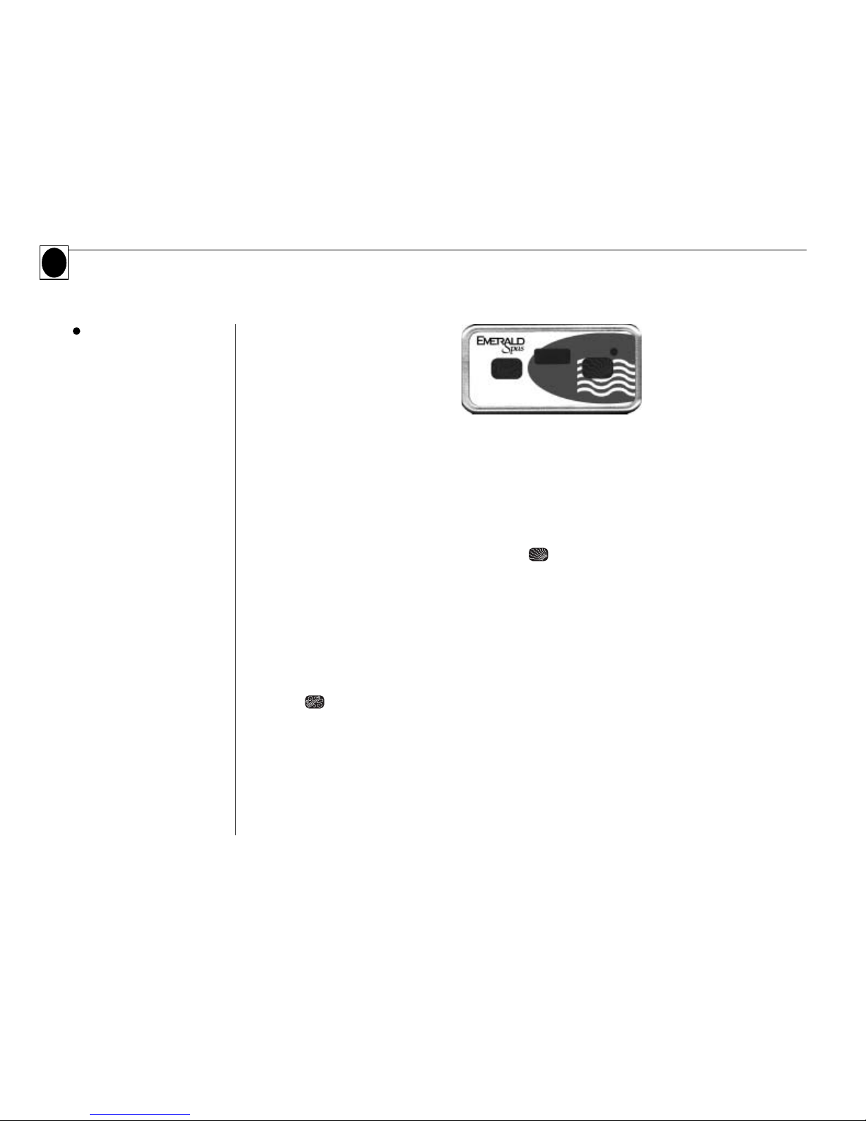
Lite Leader
Start-up
Your Lite Leader control has been specifically designed so that by simply connecting the spa to its properly
grounded source, the control will automatically heat the water to the set temperature. Your spa equipped
with the Lite Leader is shipped in the 240V configuration. See the Lite Leader schematics on page 53 if you
plan to convert the Lite Leader power system to a 120V configuration.
Temperature Adjustment (80o F - 104o F)
Temperature adjustment is controlled by pushing the pad. The display shows the actual water temperature unless the pad is pressed. When the pad is pressed, the display will show the set temperature.
Pressing the pad a second time will cause the set temperature to increase or decrease depending on what
direction was last chosen. Each successive press will change the set temperature in the same direction.
If the opposite direction is desired, release the pad and let the display revert to the actual water temperature again. Press the pad to display the set temperature, and again to make the temperature change in the
desired direction.
Light and Jets Keypad
Press the pad once to turn on the light. Press the pad again and the low-speed pump, light and ozone
generator (if installed) will operate. Press the pad a third time and the high-speed pump and light will run.
Press the pad again and only the high-speed pump will be on. Press the pad a final time to turn off all
functions. The light will automatically turn off after 4 hours of operation. The low-speed pump and ozone
generator (if installed) turn off after 2 hours, and the high-speed pump turns off after 15 minutes of operation. The low-speed pump starts automatically when the heater is turned on. If automatically activated, the
low-speed pump cannot be turned off with the function pad; however, the high-speed pump may be
started.
18
Emerald Whirlpool Spa Owner's Manual
 Loading...