

Page 1
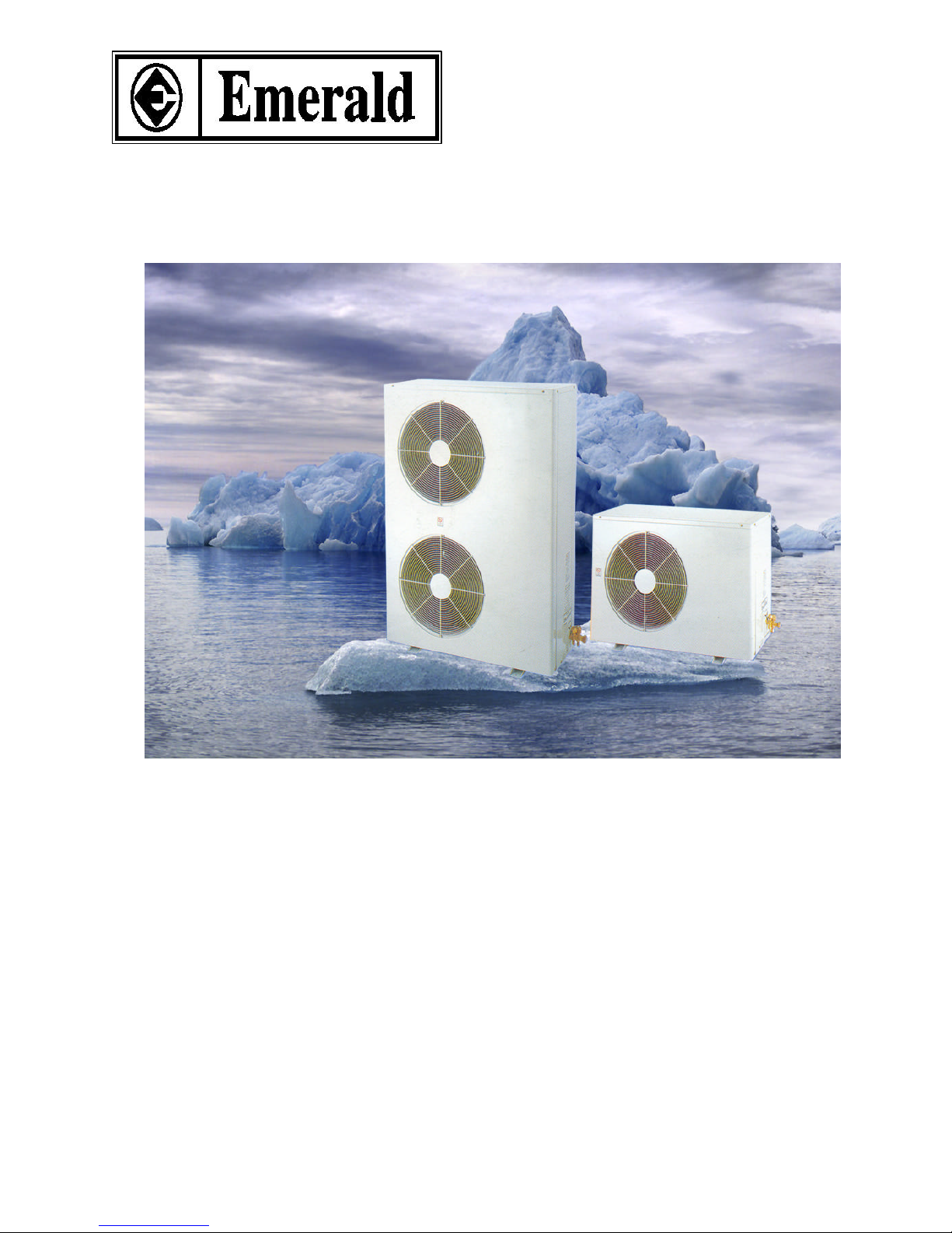
DRAFT OF TECHNICAL MANUAL FOR “LCU MODEL”
Issue by :………… Date:……… Checked by:……………… Date………… Approved by :…………….. Date:………
CONDENSING UNITCONDENSING UNIT
R-22, R407CR-22, R407C
MODELS:
LCU-07, 07R
LCU-09, 09R
LCU-12, 12R
LCU-18, 18R
LCU-24, 24R
LCU-30, 30R
LCU-36, 36R
LCU-48, 48R
LCU-56, 56R
LCU-60, 60R
Page 2
Page 3

CONTENTS PAGE
SPECIAL FEATURES
SPECIFICATIONS
NOISE LEVEL
OPERATION RANGE
REFRIGERANT CIRCUIT
OUTLINES AND DIMENSIONS
WIRING DIAGRAMS
SPECIAL PRECAUTIONS FOR R407C
INSTALLATION
PARTS LIST
TROUBLESHOOTING
SERVICE AND MAINTENANCE
Page 4

SPECIAL FEATURES
♦Quiet operation with sound insulating blanket and rubber mounting o n compressor.
♦Energy efficient and reliable rotary and scroll compressor reducing noise and vibration.
♦Rubber support on th e coil guard.
♦Extra strong molded valv e supports (1.5 mm. Thickness) for easy installation.
♦Fully charged for 5 meters refrigerant piping.
♦Extra heavy duty fan motor and motor supp ort
♦Flare couplings with three-way service valves.
♦Electrogalvanized and phosphate coated steel cabinet with bak ed-on finished coat.
♦Built-in drain pipe connect or for condense (he at pump only)
♦Hydrophilic coated aluminum fins.
Page 5
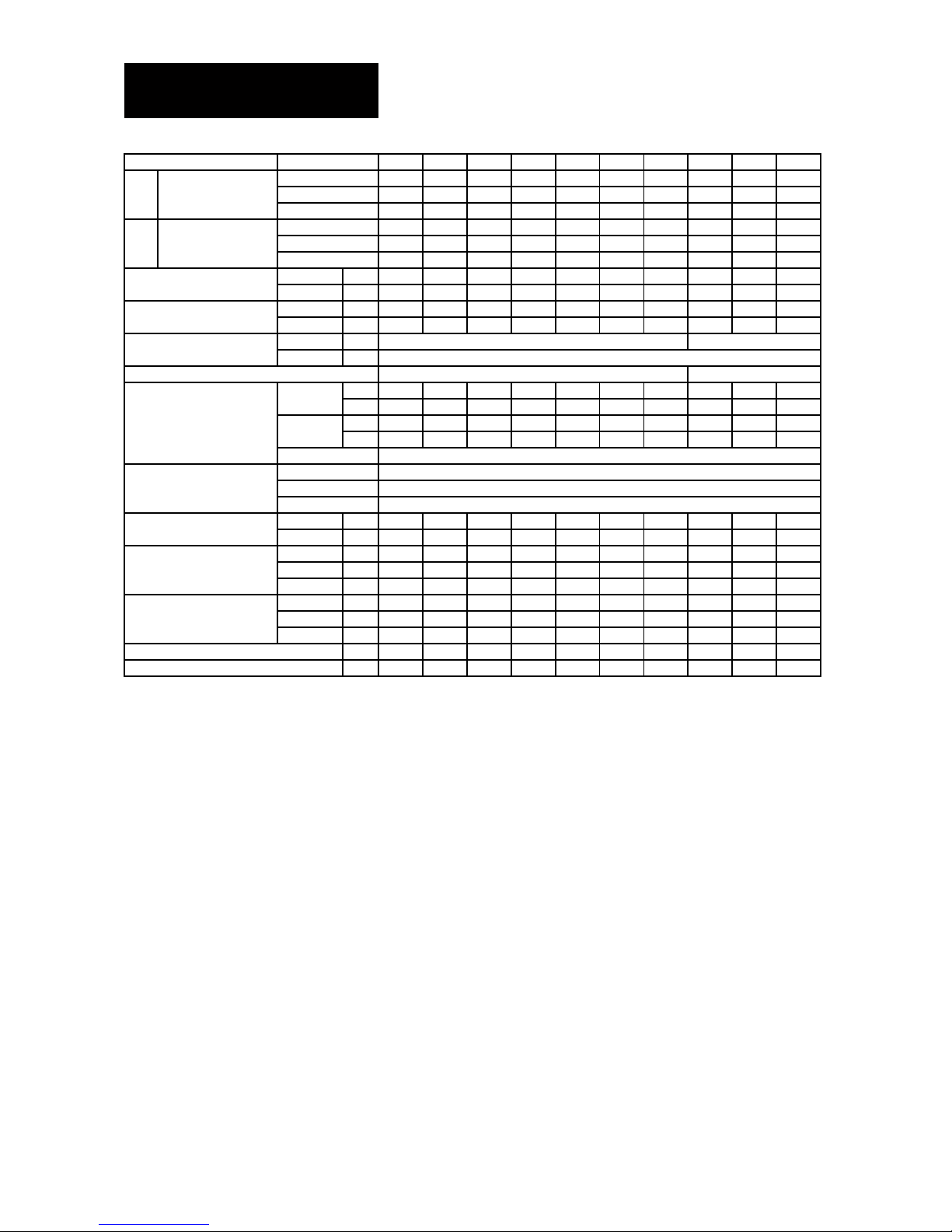
SPECIFICATIONS
COOLING ONLY R-22
CONDENSING
LCU-07
LCU-09
LCU-12
LCU-18
LCU-24
LCU-30
LCU-36
LCU-48
LCU-56
LCU-60
NOMINAL
Kcal/h
1,764
2,268
3,024
4,536
6,048
7,560
9,072
12,096
14,112
15,120
COOLING
Kw
2.05
2.64
3.52
5.28
7.03
8.79
10.55
14.07
16.41
17.58
CAPACITY
Btu/h
7,000
9,000
12,000
18,000
24,000
30,000
36,000
48,000
56,000
60,000
NOMINAL
Kcal/h
1,739
2,268
3,024
4,486
6,098
7,620
9,198
12,146
14,074
15,070
COOLING
Kw
2.02
2.64
3.52
5.22
7.09
8.86
10.7
14.13
16.37
17.53
CAPACITY
Btu/h
6,900
9,000
12,000
17,800
24,200
30,240
36,500
48,200
55,850
59,800
KW
50 Hz
0.68
0.87
1.15
1.93
2.43
2.95
3.38
4.49
5.23
5.75
KW
60 Hz
0.68
0.88
1.14
1.86
2.43
2.95
3.42
4.39
5.29
5.82A 50 Hz
3.11
3.98
5.26
8.83
11.12
13.50
15.47
6.82
7.95
8.74A 60 Hz
3.25
4.21
5.45
8.90
11.63
14.11
16.36
21.00
25.31
27.85
V/Ph/Hz
50 Hz
220-240/1/50
380-420/3/50
V/Ph/Hz
60 Hz
208-230/1/60
ROTARY
SCROLL
AIR FLOW
50 Hz
1,000
1,200
1,200
1,600
1,800
2,000
2,000
2,400
3,600
3,600
(CFM)
60 Hz
1,000
1,200
1,200
1,680
1,870
2,060
2,060
2,450
3,660
3,660
NOISE
50 Hz46484950505252545656
(dBA)
60 Hz46484950505252545656
TYPE
PROPELLER
TYPE
CORRUGATED FIN,STRAIGHT-EDGE
FIN/INCH
14
TUBE.DIA
3/8"
Liquid
mm.
6.35
6.35
6.35
9.52
9.52
9.52
9.52
12.70
12.70
12.70
Suction
mm.
9.52
9.52
12.70
15.88
15.88
15.88
15.88
19.05
19.05
19.05
HEIGHT
mm.
535
535
535
595
640
795
795
1050
1250
1250
WIDTH
mm.
765
765
765
870
970
970
970
976
976
976
DEPTH
mm.
280
280
280
320
400
400
400
400
400
400
HEIGHT
mm.
600
600
600
640
710
850
850
1,100
1,330
1,330
WIDTH
mm.
800
800
800
920
1,020
1,020
1,020
1,020
1,020
1,020
DEPTH
mm.
300
300
300
340
420
420
420
420
420
420
kg
28.00
31.00
37.00
47.00
65.00
73.00
75.00
96.00
105.00
105.00
kg
31.00
34.00
40.00
51.00
71.00
80.00
82.00
104.00
113.00
113.00
Note.
1.) THE NOMINAL COOLING CAPACITY AND ELECTRICAL CHARACTERISTICS ARE BASE ON ARI STANDARD 27
o
C DB,
19
o
C WB INDOOR AND 35
o
C DB OUTDOOR TEMP. AT HIGH SPEED.
2.) THE NOMINAL HEATING CAPACITY AND ELECTRICAL CHARACTERISTICS ARE BASE ON ARI STANDARD 20
o
C DB,
INDOOR TEMP. AND 7
o
C DB, 6
o
C WB OUTDOOR TEMP. HIGH SPEED.
3.) DUE TO CONTINUING RESEARCH IN ENERGY SAVING TECHNOLOGY, DESIGN AND SPECIFICATIONS ARE SUBJECT
TO CHANGE WITHOUT NOTICE
MODEL
DIMENSION
CONNECTION
NOMINAL TOTAL POWER
60 Hz
PACKING DIMENSION
COMPRESSOR TYPE
FAN
NET WEIGHT
GROSS WEIGHT
50 Hz
POWER SOURCE
NOMINAL TOTAL CURRENT
COIL
Page 6
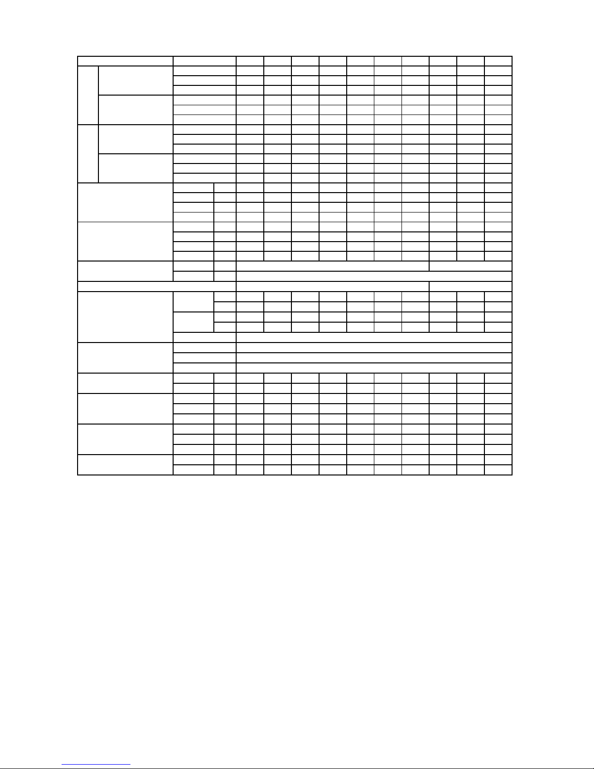
HEAT PUMP R-22
CONDENSING
LCU-07
LCU-09
LCU-12
LCU-18
LCU-24
LCU-30
LCU-36
LCU-48
LCU-56
LCU-60
NOMINAL
Kcal/h
1,688
2,218
2,969
4,486
6,010
7,484
8,971
11,985
13,986
14,969
COOLING
Kw
1.96
2.58
3.45
5.22
6.99
8.70
10.43
13.94
16.27
17.41
CAPACITY
Btu/h
6,700
8,800
11,780
17,800
23,850
29,700
35,600
47,560
55,500
59,400
NOMINAL
Kcal/h
1,865
2,381
3,150
4,649
6,174
7,762
9,173
12,146
14,162
15,145
HEATING
Kw
2.17
2.77
3.66
5.41
7.18
9.03
10.67
14.13
16.47
17.61
CAPACITY
Btu/h
7,400
9,450
12,500
18,450
24,500
30,800
36,400
48,200
56,200
60,100
NOMINAL
Kcal/h
1,688
2,230
2,948
4,435
6,023
7,522
9,022
12,020
13,986
14,944
COOLING
Kw
1.96
2.59
3.43
5.16
7.00
8.75
10.49
13.98
16.27
17.38
CAPACITY
Btu/h
6,700
8,850
11,700
17,600
23,900
29,850
35,800
47,700
55,500
59,300
NOMINAL
Kcal/h
1,840
2,381
3,175
4,637
6,199
7,787
9,223
12,184
14,162
15,170
HEATING
Kw
2.14
2.77
3.69
5.39
7.21
9.06
10.73
14.17
16.47
17.64
CAPACITY
Btu/h
7,300
9,450
12,600
18,400
24,600
30,900
36,600
48,350
56,200
60,200
NOMINAL TOTAL POWER
COOLING
50 Hz
0.67
0.85
1.13
1.90
2.42
2.92
3.35
4.46
5.20
5.71
(kw)
HEATING
50 Hz
0.66
0.83
1.11
1.88
2.41
2.90
3.33
4.43
5.18
5.68
COOLING
60 Hz
0.67
0.87
1.12
1.85
2.41
2.92
3.40
4.37
5.26
5.80
HEATING
60 Hz
0.66
0.85
1.10
1.83
2.39
2.90
3.38
4.34
5.24
5.77
NOMINAL TOTAL CURRENT
COOLING
50 Hz
3.07
3.89
5.17
8.70
11.08
13.36
15.33
6.78
7.09
8.68
(A)
HEATING
50 Hz
3.02
3.80
5.08
8.60
11.03
13.27
15.24
6.73
7.87
8.63
COOLING
60 Hz
3.21
4.16
5.36
8.85
11.53
13.97
16.27
20.91
25.17
27.75
HEATING
60 Hz
3.16
4.07
5.26
8.76
11.44
13.88
16.17
20.77
25.07
27.61
V/Ph/Hz
50 Hz
220-240/1/50
380-420/3/50
V/Ph/Hz
60 Hz
208-230/1/60
ROTARY
SCROLL
AIR FLOW
50 Hz
1,000
1,200
1,200
1,600
1,800
2,000
2,000
2,400
3,600
3,600
(CFM)
60 Hz
1,000
1,200
1,200
1,680
1,870
2,060
2,060
2,450
3,660
3,660
NOISE
50 Hz46484950505252545656
(dBA)
60 Hz46484950505252545656
TYPE
PROPELLER
TYPE
CORRUGATED FIN,STRAIGHT-EDGE
FIN/INCH
14
TUBE.DIA
3/8"
Liquid
mm.
6.35
6.35
6.35
9.52
9.52
9.52
9.52
12.70
12.70
12.70
Suction
mm.
9.52
9.52
12.70
15.88
15.88
15.88
15.88
19.05
19.05
19.05
HEIGHT
mm.
535
535
535
595
640
795
795
1050
1250
1250
WIDTH
mm.
765
765
765
870
970
970
970
976
976
976
DEPTH
mm.
280
280
280
320
400
400
400
400
400
400
HEIGHT
mm.
600
600
600
640
710
850
850
1,100
1,330
1,330
WIDTH
mm.
800
800
800
920
1,020
1,020
1,020
1,020
1,020
1,020
DEPTH
mm.
300
300
300
340
420
420
420
420
420
420
NET WEIGHT
kg
28.00
31.00
37.00
47.00
65.00
73.00
75.00
96.00
105.00
105.00
GROSS WEIGHT
kg
31.00
34.00
40.00
51.00
71.00
80.00
82.00
104.00
113.00
113.00
Note.
1.) THE NOMINAL COOLING CAPACITY AND ELECTRICAL CHARACTERISTICS ARE BASE ON ARI STANDARD 27
o
C DB,
19
o
C WB INDOOR AND 35
o
C DB OUTDOOR TEMP. AT HIGH SPEED.
2.) THE NOMINAL HEATING CAPACITY AND ELECTRICAL CHARACTERISTICS ARE BASE ON ARI STANDARD 20
o
C DB,
INDOOR TEMP. AND 7
o
C DB, 6
o
C WB OUTDOOR TEMP. HIGH SPEED.
3.) DUE TO CONTINUING RESEARCH IN ENERGY SAVING TECHNOLOGY, DESIGN AND SPECIFICATIONS ARE SUBJECT
TO CHANGE WITHOUT NOTICE
CONNECTION
DIMENSION
POWER SOURCE
COMPRESSOR TYPE
FAN
COIL
PACKING DIMENSION
WEIGHT
MODEL
50 Hz60 Hz
Page 7
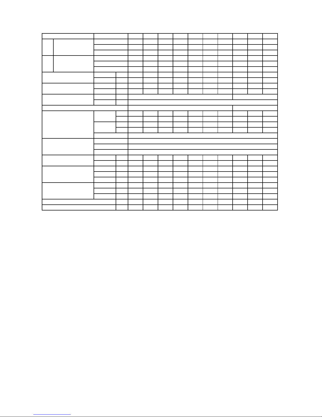
COOLING ONLY R-407C
CONDENSING
LCU-07
LCU-09
LCU-12
LCU-18
LCU-24
LCU-30
LCU-36
LCU-48
LCU-56
LCU-60
NOMINAL
Kcal/h
1,764
2,268
3,024
4,536
6,048
7,560
9,072
12,096
14,112
15,120
COOLING
Kw
2.05
2.64
3.52
5.28
7.03
8.79
10.55
14.07
16.41
17.58
CAPACITY
Btu/h
7,000
9,000
12,000
18,000
24,000
30,000
36,000
48,000
56,000
60,000
NOMINAL
Kcal/h
1,764
2,268
3,024
4,536
6,048
7,560
9,072
12,096
14,112
15,120
COOLING
Kw
2.05
2.64
3.52
5.28
7.03
8.79
10.55
14.07
16.41
17.58
CAPACITY
Btu/h
7,000
9,000
12,000
18,000
24,000
30,000
36,000
48,000
56,000
60,000
KW
50 Hz
0.69
0.86
1.16
1.93
2.45
2.96
3.38
4.50
5.24
5.75
KW
60 Hz
0.69
0.89
1.15
1.87
2.43
2.95
3.43
4.40
5.29
5.84A 50 Hz
3.30
4.11
5.55
9.23
11.72
14.16
16.17
6.84
7.96
8.74A 60 Hz
3.30
4.26
5.50
8.95
11.63
14.11
16.41
21.05
25.31
27.94
V/Ph/Hz
50 Hz
220-240/1/50
380-420/3/50
V/Ph/Hz
60 Hz
208-230/1/60
ROTARY
SCROLL
AIR FLOW
50 Hz
1,000
1,200
1,200
1,600
1,800
2,000
2,000
2,400
3,600
3,600
(CFM)
60 Hz
1,000
1,200
1,200
1,680
1,870
2,060
2,060
2,450
3,660
3,660
NOISE
50 Hz46484950505252545656
(dBA)
60 Hz46484950505252545656
TYPE
PROPELLER
TYPE
CORRUGATED FIN,STRAIGHT-EDGE
FIN/INCH
14
TUBE.DIA
3/8"
Liquid
mm.
6.35
6.35
6.35
9.52
9.52
9.52
9.52
12.70
12.70
12.70
Suction
mm.
9.52
9.52
12.70
15.88
15.88
15.88
15.88
19.05
19.05
19.05
HEIGHT
mm.
535
535
535
595
640
795
795
1050
1250
1250
WIDTH
mm.
765
765
765
870
970
970
970
976
976
976
DEPTH
mm.
280
280
280
320
400
400
400
400
400
400
HEIGHT
mm.
600
600
600
640
710
850
850
1,100
1,330
1,330
WIDTH
mm.
800
800
800
920
1,020
1,020
1,020
1,020
1,020
1,020
DEPTH
mm.
300
300
300
340
420
420
420
420
420
420
kg
28.00
31.00
37.00
47.00
65.00
73.00
75.00
96.00
105.00
105.00
kg
31.00
34.00
40.00
51.00
71.00
80.00
82.00
104.00
113.00
113.00
Note.
1.) THE NOMINAL COOLING CAPACITY AND ELECTRICAL CHARACTERISTICS ARE BASE ON ARI STANDARD 27
o
C DB,
19
o
C WB INDOOR AND 35
o
C DB OUTDOOR TEMP. AT HIGH SPEED.
2.) THE NOMINAL HEATING CAPACITY AND ELECTRICAL CHARACTERISTICS ARE BASE ON ARI STANDARD 20
o
C DB,
INDOOR TEMP. AND 7
o
C DB, 6
o
C WB OUTDOOR TEMP. HIGH SPEED.
3.) DUE TO CONTINUING RESEARCH IN ENERGY SAVING TECHNOLOGY, DESIGN AND SPECIFICATIONS ARE SUBJECT
TO CHANGE WITHOUT NOTICE
NET WEIGHT
GROSS WEIGHT
NOMINAL TOTAL CURRENT
POWER SOURCE
MODEL
50 Hz60 Hz
NOMINAL TOTAL POWER
COMPRESSOR TYPE
FAN
COIL
CONNECTION
DIMENSION
PACKING DIMENSION
Page 8
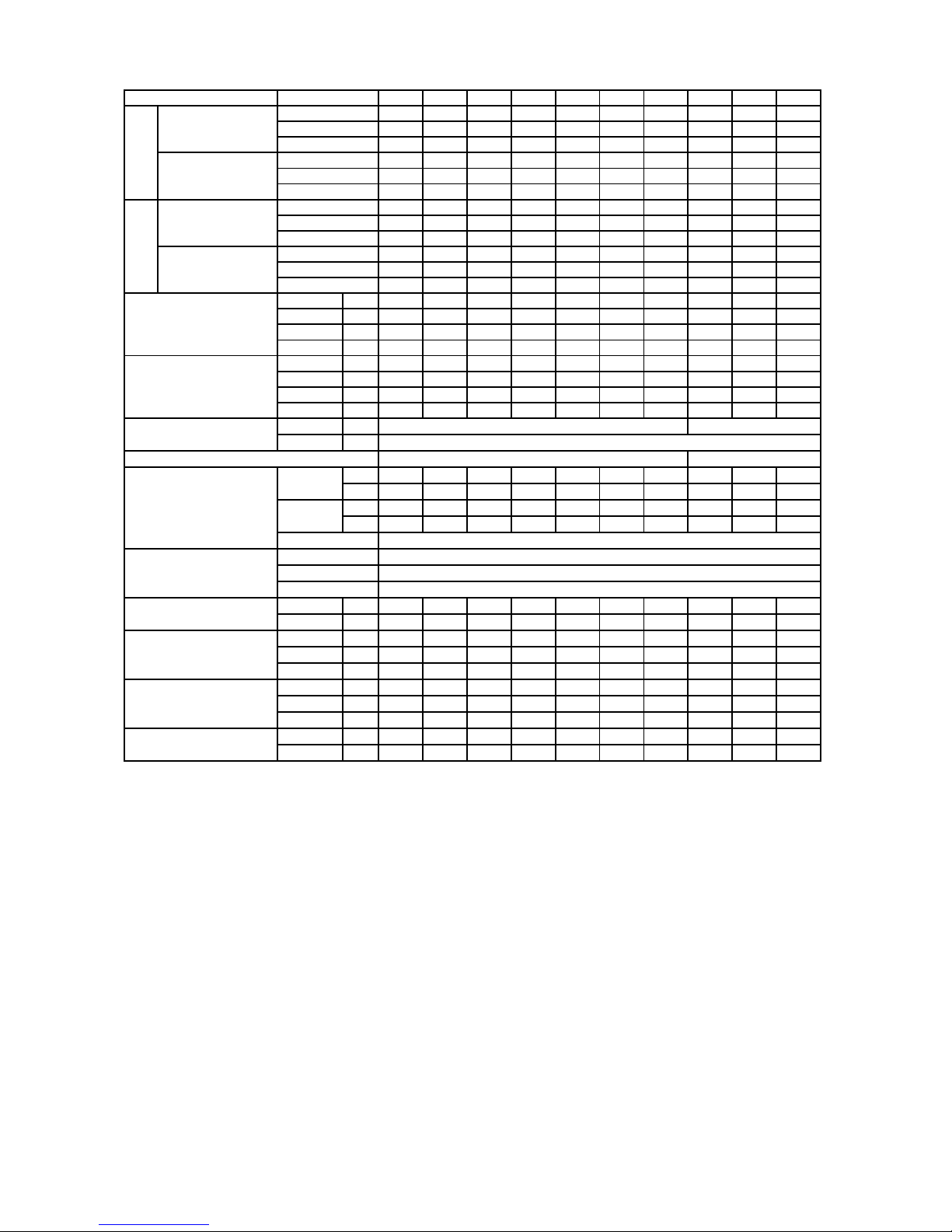
HEAT PUMP R-407C
CONDENSING
LCU-07
LCU-09
LCU-12
LCU-18
LCU-24
LCU-30
LCU-36
LCU-48
LCU-56
LCU-60
NOMINAL
Kcal/h
1,764
2,268
3,024
4,536
6,048
7,560
9,072
12,096
14,112
15,120
COOLING
Kw
2.05
2.64
3.52
5.28
7.03
8.79
10.55
14.07
16.41
17.58
CAPACITY
Btu/h
7,000
9,000
12,000
18,000
24,000
30,000
36,000
48,000
56,000
60,000
NOMINAL
Kcal/h
1,865
2,394
3,175
4,662
6,174
7,762
9,223
12,197
14,188
15,246
HEATING
Kw
2.17
2.78
3.69
5.42
7.18
9.03
10.73
14.19
16.50
17.73
CAPACITY
Btu/h
7,400
9,500
12,600
18,500
24,500
30,800
36,600
48,400
56,300
60,500
NOMINAL
Kcal/h
1,764
2,268
3,024
4,536
6,048
7,560
9,072
12,096
14,112
15,120
COOLING
Kw
2.05
2.64
3.52
5.28
7.03
8.79
10.55
14.07
16.41
17.58
CAPACITY
Btu/h
7,000
9,000
12,000
18,000
24,000
30,000
36,000
48,000
56,000
60,000
NOMINAL
Kcal/h
1,865
2,394
3,200
4,687
6,224
7,787
9,248
12,222
14,213
15,221
HEATING
Kw
2.17
2.78
3.72
5.45
7.24
9.06
10.76
14.21
16.53
17.70
CAPACITY
Btu/h
7,400
9,500
12,700
18,600
24,700
30,900
36,700
48,500
56,400
60,400
NOMINAL TOTAL POWER
COOLING
50 Hz
0.68
0.85
1.15
1.92
2.44
2.95
3.37
4.49
5.23
5.73
(kw)
HEATING
50 Hz
0.67
0.84
1.14
1.90
2.41
2.93
3.35
4.46
5.20
5.70
COOLING
60 Hz
0.68
0.88
1.14
1.86
2.42
2.94
3.42
4.39
5.28
5.82
HEATING
60 Hz
0.67
0.86
1.13
1.84
2.39
2.92
2.40
4.36
5.25
5.79
NOMINAL TOTAL CURRENT
COOLING
50 Hz
3.25
4.07
5.50
9.19
11.67
14.11
16.12
6.82
7.95
8.71
(A)
HEATING
50 Hz
3.21
4.02
5.45
9.09
11.53
14.02
16.03
6.78
7.90
8.66
COOLING
60 Hz
3.25
4.21
5.45
8.90
11.58
14.07
16.36
21.00
25.26
27.85
HEATING
60 Hz
3.21
4.11
5.41
8.80
11.44
13.97
11.48
20.86
25.12
27.70
V/Ph/Hz
50 Hz
220-240/1/50
380-420/3/50
V/Ph/Hz
60 Hz
208-230/1/60
ROTARY
SCROLL
AIR FLOW
50 Hz
1,000
1,200
1,200
1,600
1,800
2,000
2,000
2,400
3,600
3,600
(CFM)
60 Hz
1,000
1,200
1,200
1,680
1,870
2,060
2,060
2,450
3,660
3,660
NOISE
50 Hz46484950505252545656
(dBA)
60 Hz46484950505252545656
TYPE
PROPELLER
TYPE
CORRUGATED FIN,STRAIGHT-EDGE
FIN/INCH
14
TUBE.DIA
3/8"
Liquid
mm.
6.35
6.35
6.35
9.52
9.52
9.52
9.52
12.70
12.70
12.70
Suction
mm.
9.52
9.52
12.70
15.88
15.88
15.88
15.88
19.05
19.05
19.05
HEIGHT
mm.
535
535
535
595
640
795
795
1050
1250
1250
WIDTH
mm.
765
765
765
870
970
970
970
976
976
976
DEPTH
mm.
280
280
280
320
400
400
400
400
400
400
HEIGHT
mm.
600
600
600
640
710
850
850
1,100
1,330
1,330
WIDTH
mm.
800
800
800
920
1,020
1,020
1,020
1,020
1,020
1,020
DEPTH
mm.
300
300
300
340
420
420
420
420
420
420
NET WEIGHT
kg
28.00
31.00
37.00
47.00
65.00
73.00
75.00
96.00
105.00
105.00
GROSS WEIGHT
kg
31.00
34.00
40.00
51.00
71.00
80.00
82.00
104.00
113.00
113.00
Note.
1.) THE NOMINAL COOLING CAPACITY AND ELECTRICAL CHARACTERISTICS ARE BASE ON ARI STANDARD 27
o
C DB,
19
o
C WB INDOOR AND 35
o
C DB OUTDOOR TEMP. AT HIGH SPEED.
2.) THE NOMINAL HEATING CAPACITY AND ELECTRICAL CHARACTERISTICS ARE BASE ON ARI STANDARD 20
o
C DB,
INDOOR TEMP. AND 7
o
C DB, 6
o
C WB OUTDOOR TEMP. HIGH SPEED.
3.) DUE TO CONTINUING RESEARCH IN ENERGY SAVING TECHNOLOGY, DESIGN AND SPECIFICATIONS ARE SUBJECT
TO CHANGE WITHOUT NOTICE
MODEL
50 Hz
COMPRESSOR TYPE
60 Hz
DIMENSION
PACKING DIMENSION
WEIGHT
FAN
COIL
CONNECTION
POWER SOURCE
Page 9
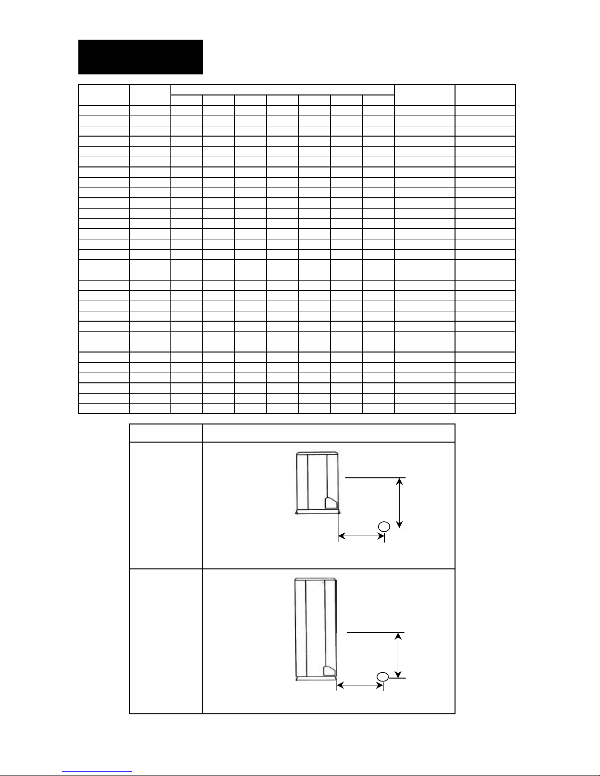
NOISE LEVEL
Model
Speed
1/1 Octave Sound pressure level (dB, ref 20
µ
Pa)
Overall
Noise
125Hz
250Hz
500Hz
1kHz
2kHz
4kHz
8kHz
A(dBA)
Criteria
LCU-07
High
56
55
50
47
42
31
24
52
46
Medium
545246423727224842
Low474639343022.6204138LCU-09
High
58
57
52
49
44
38
26
54
48
Medium
565448443934245044
Low
49
48
41
39
32
30
22
43
40
LCU-12
High
59
58
53
50
45
32
27
55
49
Medium
5755494540
28.8255145Low504944403326.5234441LCU-18
High
58
57
53
50
44
40
30
54
50
Medium
555448474135275145
Low484741403428204438LCU-24
High
60
57
54
50
48
40
32
54
50
Medium
575450484337295348
Low535047453832265046LCU-30
High
62
61
56
53
48
42
30
58
52
Medium
605852484338285448
Low535245433634264744LCU-36
High
62
61
56
53
48
39.2
30
58
52
Medium
6058524843
34.6285448Low535248433630.8264744LCU-48
High
62
61
57
54
48
44
34
58
54
Medium
595852514539315549
Low
52
51
45
44
38
32
24
48
42
LCU-56
High
66
63
60
57.4
54
46
38
60
56
Medium
636056544943355954
Low
59
56
53
51
44
38
32
56
52
LCU-60
High
66
63
60
57.2
54
46
38
60
56
Medium
636056544943355954
Low5956535144383256
52
Model
Measuring location
LCU-07
LCU-09
LCU-12
LCU-18
LCU-24
LCU-30
LCU-36
LCU-48
LCU-56
LCU-60
0.8
m
1
m
Microphone
1
m
Microphone
Page 10
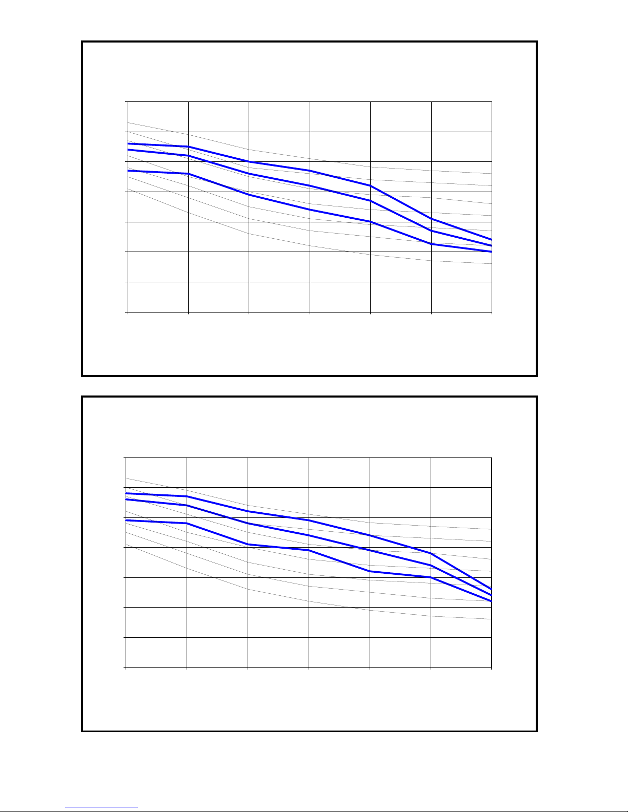
LCU-07 CURVES
0
10
20
30
40
50
60
70
125 250 500 1000 2000 4000 8000
Octave-band frequency (Hz)
Sound pressure level
High fan
Medium fan
Low fan
NC-50
NC-45
NC-40
NC-35
NC-30
NC-20
NC-25
LCU-09 CURVES
0
10
20
30
40
50
60
70
125 250 500 1000 2000 4000 8000
Octave-band frequency (Hz)
Sound pressure level
High fan
Medium fan
Low fan
NC-50
NC-45
NC-40
NC-35
NC-30
NC-25
NC-20
Page 11
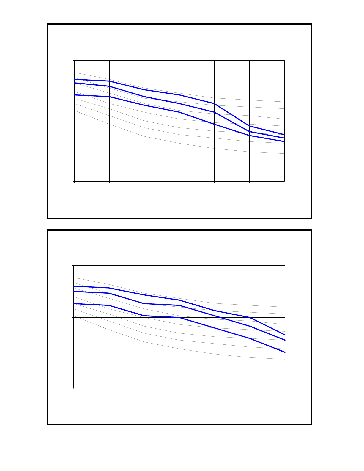
LCU-12 CURVES
0
10
20
30
40
50
60
70
125 250 500 1000 2000 4000 8000
Octave-band frequency (Hz)
Sound pressure level
NC-50
NC-45
NC-40
NC-35
NC-30
NC-25
NC-20
High fan
Medium fan
Low fan
LCU-18 CURVES
0
10
20
30
40
50
60
70
125 250 500 1000 2000 4000 8000
Octave-band frequency (Hz)
Sound pressure level
NC-30
NC-20
NC-40
NC-25
NC-45
NC-35
NC-50
High fan
Medium fan
Low fan
Page 12
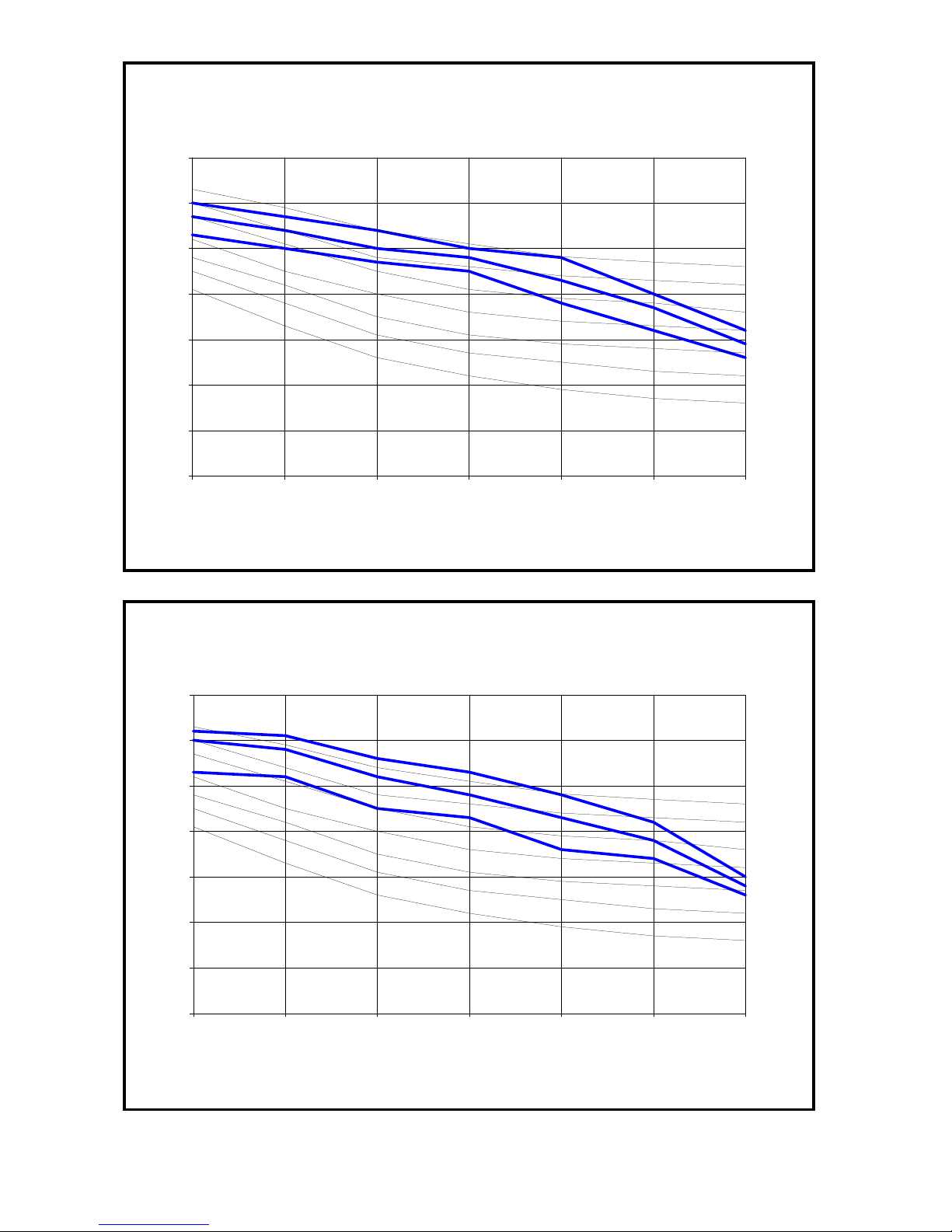
LCU-24 CURVES
0
10
20
30
40
50
60
70
125 250 500 1000 2000 4000 8000
Octave-band frequency (Hz)
Sound pressure level
NC-50
NC-45
NC-40
NC-35
NC-30
NC-25
NC-20
High fan
Medium fan
Low fan
LCU-30 CURVES
0
10
20
30
40
50
60
70
125 250 500 1000 2000 4000 8000
Octave-band frequency (Hz)
Sound pressure level
NC-30
NC-20
NC-40
NC-25
NC-45
NC-35
NC-50
High fan
Medium fan
Low fan
Page 13
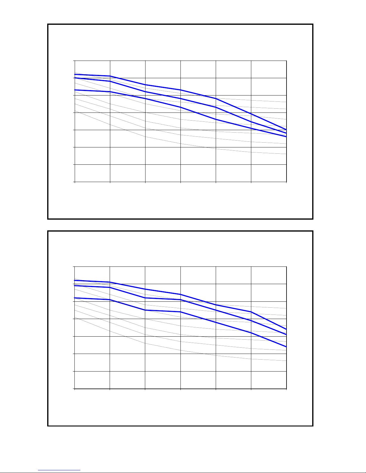
LCU-36 CURVES
0
10
20
30
40
50
60
70
125 250 500 1000 2000 4000 8000
Octave-band frequency (Hz)
Sound pressure level
NC-50
NC-45
NC-40
NC-35
NC-30
NC-25
NC-20
High fan
Medium fan
Low fan
LCU-48 CURVES
0
10
20
30
40
50
60
70
125 250 500 1000 2000 4000 8000
Octave-band frequency (Hz)
Sound pressure level
NC-30
NC-20
NC-40
NC-25
NC-45
NC-35
NC-50
High fan
Medium fan
Low fan
Page 14
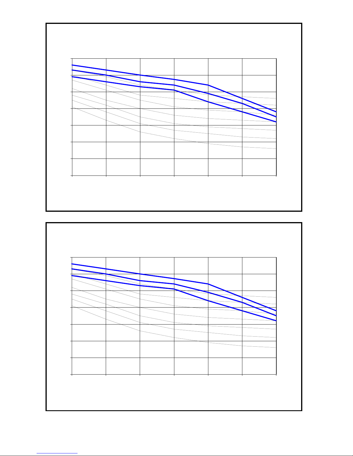
LCU-56 CURVES
0
10
20
30
40
50
60
70
125 250 500 1000 2000 4000 8000
Octave-band frequency (Hz)
Sound pressure level
NC-50
NC-45
NC-40
NC-35
NC-30
NC-25
NC-20
High fan
Medium fan
Low fan
LCU-60 CURVES
0
10
20
30
40
50
60
70
125 250 500 1000 2000 4000 8000
Octave-band frequency (Hz)
Sound pressure level
NC-30
NC-20
NC-40
NC-25
NC-45
NC-35
NC-50
High fan
Medium fan
Low fan
Page 15
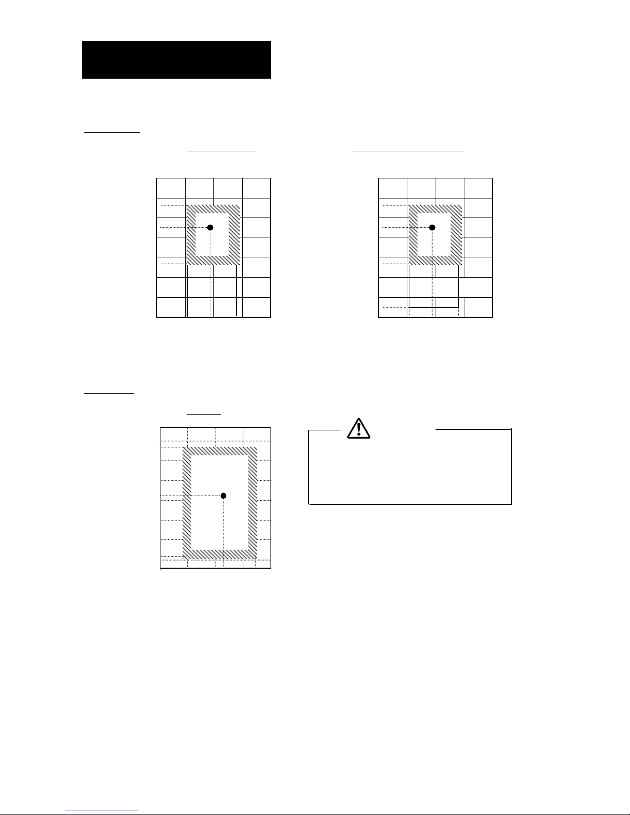
OPERATION RANGE
Ensure the operating temperature is in allowable range
Cooling only
Cooling Standard Cooling with low ambient kit
LOW AMBIENT KIT
Indoor temp.(oCWB) Indoor temp.(oCWB)
Heat pump
Heating
Caution:
The use of your air conditioner outside the
range of working temperature and humidity
can result in serious failure.
Indoor temp.(oCDB)
Outdoor temp.(
o
CDB)Outdoor temp.(
o
CWB)
Outdoor temp.(
o
CDB)
STD
21
15233543-91520
7
18
STD
27
STD
-5211523354319
19
Page 16
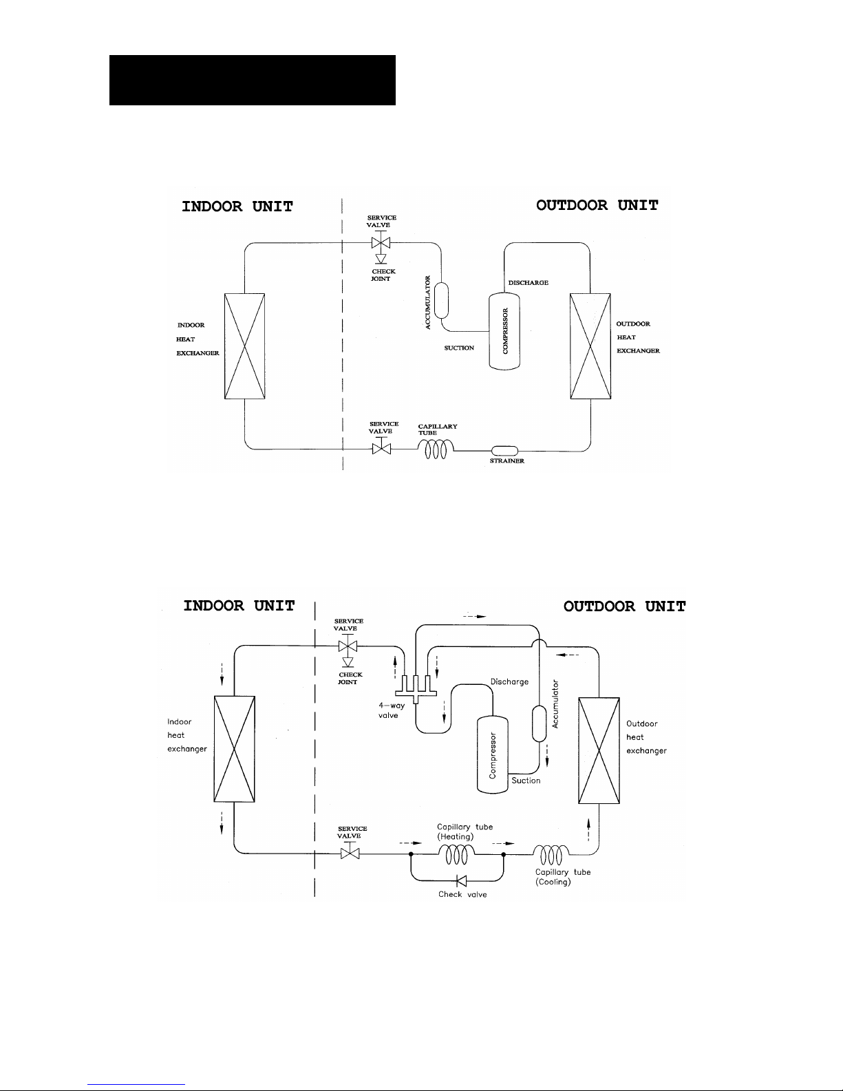
REFRIGERANT CIRCUIT
MODEL: INDOOR UNIT (COOLING) / LCU
MODEL: INDOOR UNIT (HEATING) / LCU
Page 17
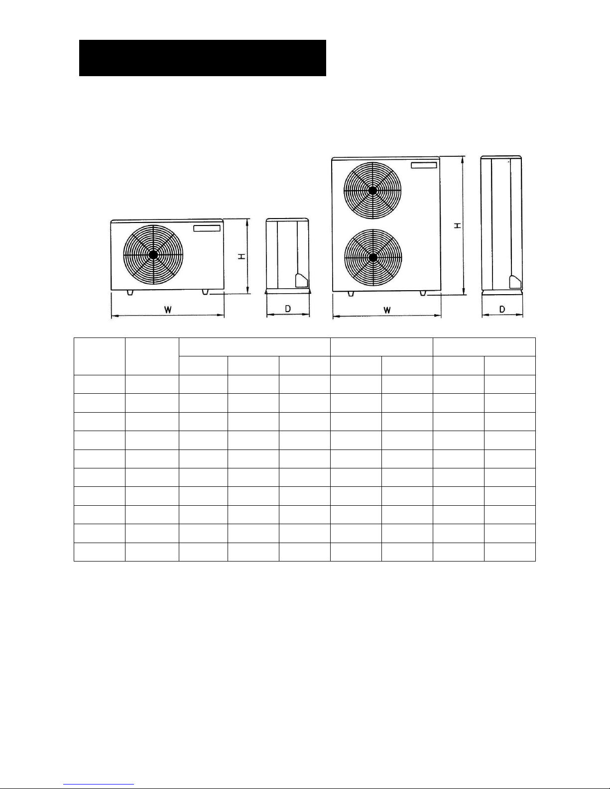
OUTLINES AND DIMENSIONS
OUTDOOR UNIT
MODEL: LCU SERIES (COOLING ONLY AND HEAT PUMP)
DIMENSION (mm) CONNECTION WEIGHT
MODEL
CAPACITY
(BTU/H)
H W D LIQUID SUCTION NET GROSS
LCU-07 7,000 535 765 280
!
"
#
$
28 31
LCU-09 9,000 535 765 280
!
"
#
$
31 34
LCU-12 12,000 535 765 280
!%
37 40
LCU-18 18,000 595 870 320
"
#
$
&
#
$
47 51
LCU-24 24,000 640 970 400
"
#
$
&
#
$
65 71
LCU-30 30,000 795 970 400
"
#
$
&
#
$
73 80
LCU-36 36,000 95 970 400
"
#
$
&
#
$
75 82
LCU-48 48,000 1,050 976 400
%'
96 104
LCU-56 56,000 1,250 976 400
%
'
105 113
LCU-60 60,000 1,250 976 400
%
'
105 113
LCU-07, 09, 12, 18, 24, 30, 36
LCU-48, 56, 60
Page 18
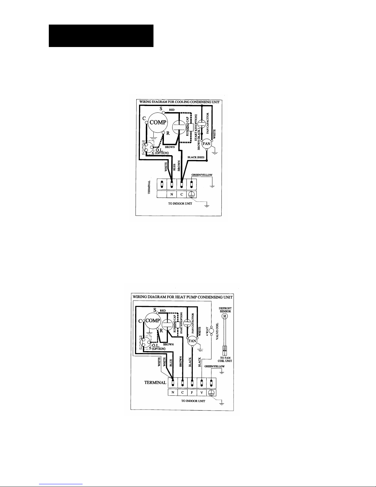
WIRING DIAGRAMS
COOLING ONLY
CONDENSING UNIT MODEL: LCU-07, 09, 12 MATCH LCU
HEATPUMP
CONDENSING UNIT MODEL: LCU-07R, 09R, 12R MATCH LCU
Page 19
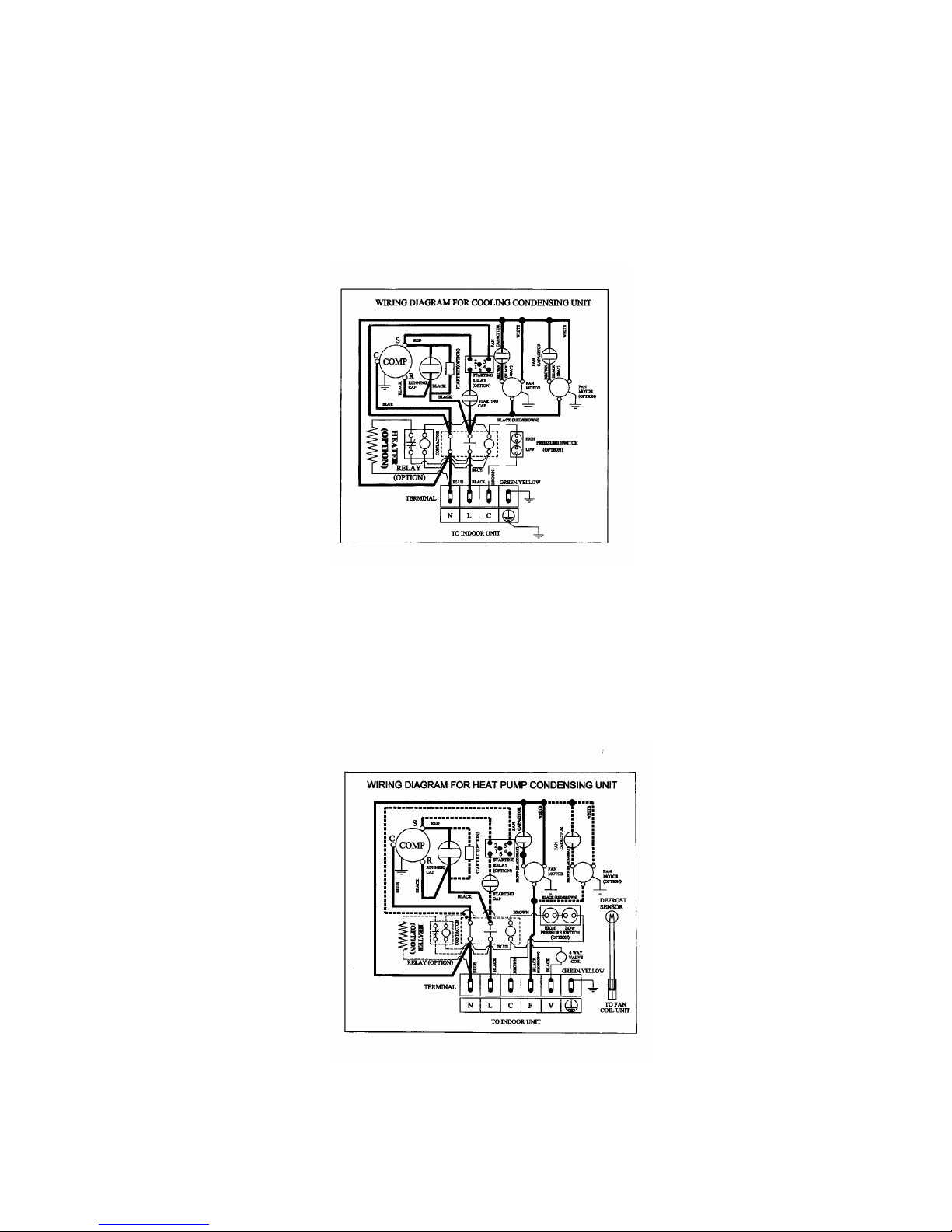
COOLING ONLY
CONDENSING UNIT MODEL: LCU-18, 24, 36 MATCH LCU
HEATPUMP
CONDENSING UNIT MODEL: LCU-18R, 24R, 36R MATCH LCU
Page 20
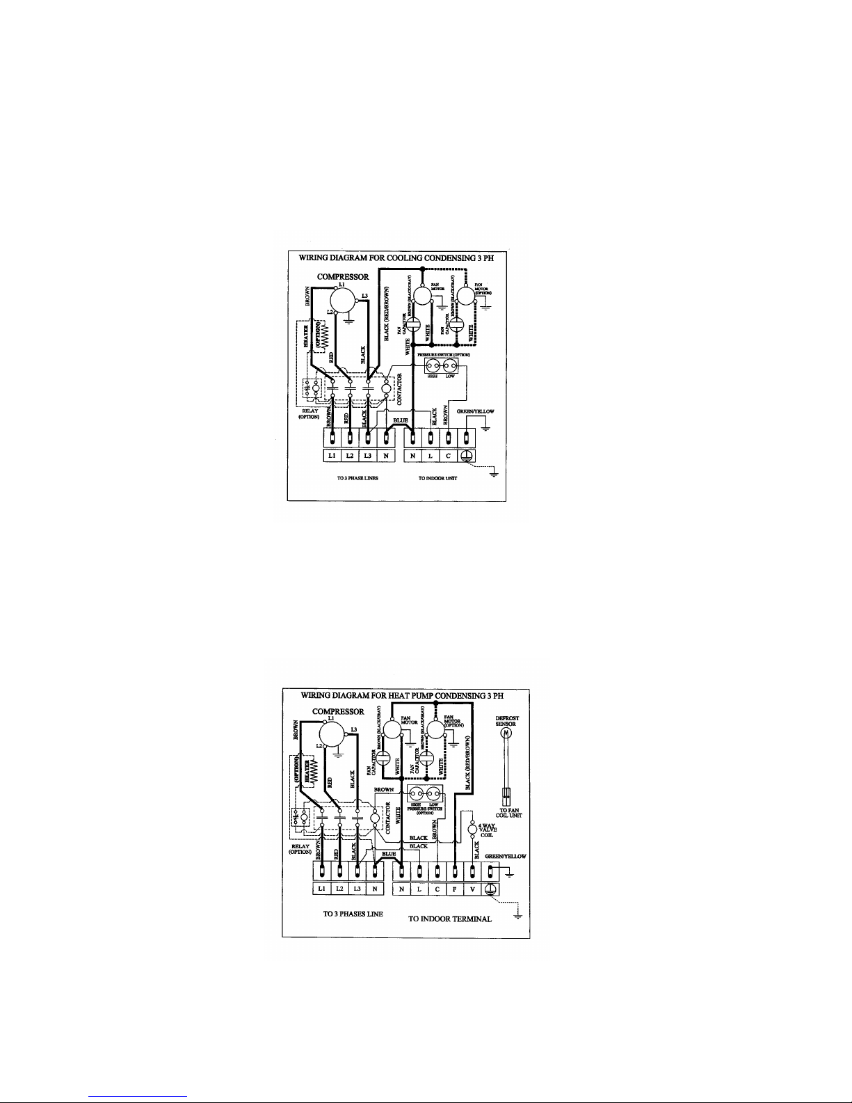
COOLING ONLY
CONDENSING UNIT MODEL: LCU-48, 56, 60 MATCH LCU.
HEATPUMP
CONDENSING UNIT MODEL: LCU-48R, 56R, 60R MATCH LCU
Page 21

SPECIAL PRECAUTIONS FOR R407C
!"##$%$&'$()$*+$$&(%,--(.&!(%,/01'
1.
WHY COME TO R-407C
Recognizing the global nature of the problem, on September 16,1987, in Montreal, Canada, 24 nations and the
European Economic Community (EEC) signed the Montreal Protocol on Subs tances that Deplete the Ozone layer.
Now focus is on HCFCs in air conditioning and refrigeration, The industry is looking at the trans ition from R-22 to
longer-term HFC alternatives. R-407C became a popular option from manufacturer who wanted to quickly move to
an HFC alternative due to its characteristics similar to R-22.
2.
THE DIFFERENCE OF R-407C
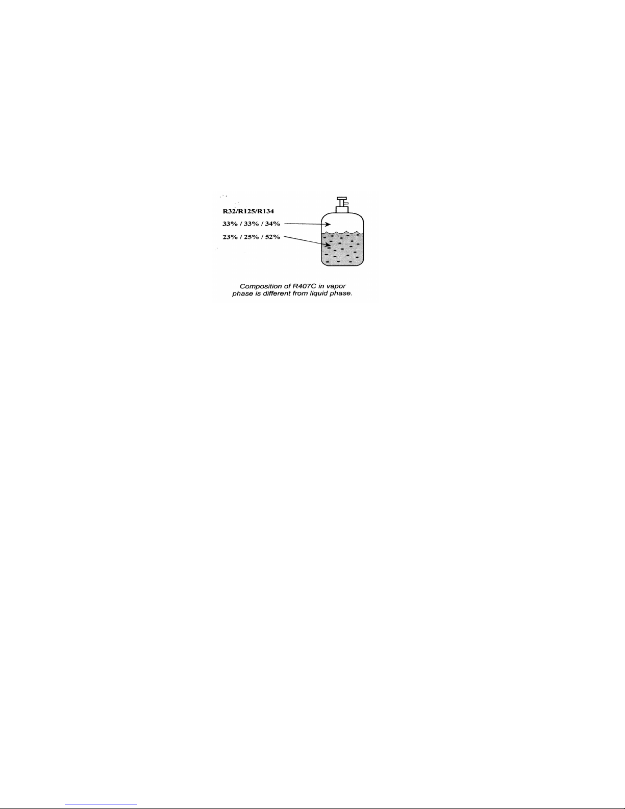
R-22 is pure compound but R407C is a zeotropic refrigerant mixture, which consist of R-32 (23%), R-125 (25%),
and R-134a (52%)
R-22 use mineral oil as its lubricant but R-407C requires Polyol ester oil (POE)
The capacity and performance of R-407C is nearly same as R22.
3.CHARACTERISTICS
R407C liquid and vapour components have different compositions when the fluid evaporates or condenses.
Hence, when leak occurs and only vapour leaks out, the composition of the refrigerant mixture left in the system will
change and subsequently affect the system performance. If just additional refrigerant is added to leak system,
system performance will drop. It is recommended that the system should be evacuated thoroughly before
recharging with R407C.
When refrigerant R407C is used, the composition will differ depending on whether it is in gaseous or liquid
phase. Hence when charging R407C, ensure that only liquid is being withdrawn from the cylinder or can. This is to
make certain that only original composition of R407C is being charged into the system.
POE oil is used as lubricant for R407C compressor, which is different from the mineral oil used for R22
compressor. POE absorbs more moisture. As a result, POE must be handled more carefully and compressor and
system processing procedure must be more rigorous to avoid absorbing moisture. And also POE are better solvents
which means they will dislodge and carry debris through a systems to a far greater than do mineral oils. Because of
these characteristics, it is more important than ever to pay particular attention to adequate use of filters and dryer in
the design and service.
4.PRECAUTIONS FOR R-407C
Check list before installation/servicing
TUBING
Refrigerant R407C is more easily affected by dust of moisture compared with R22, make sure to temporarily
cover the ends of the tubing prior to installat i on
Page 22
COMPRESSOR OIL
No additional charge of compressor oil is permitted.
REFRIGERANT
No other refrigerant other that R407C
TOOLS
Tools specifically for R407C only (must not be used for R22 or other refrigerant)
1.! Manifold gauge and charging hose
2.! Gas leak detector
3.! Refrigerant cylinder/charging cylinder
4.! Vacuum pump c/w adapter
5.! Flare tools
6.! Refrigerant recovery machine
5. HANDLING AND INSTALLATION GUIDELINES
Like R22 system, the handling and installation of R407C system are closely similar. All precautionary measures;
such as ensuring no moisture, no dirt or chips in the system, clean brazing using nitrogen, and thorough leak check
and vacuuming are equally important requirements. However, due to zeotropic nature of R407C and its hydroscopic
POE oil, additional precautions must be taken to ens ure optimum and trouble-free system operation.
5.1) Filter-dryer must be installed along the liquid line for all R407C air conditioners. This is to minimise the
contamination of moisture and dirt in the refrigerant system. Filter-dryer must be of molecular sieve type. For a
heat-pump system, install a two-way flow filter dryer along the liquid line.
5.2) During installation or servicing, avoid prolong exposure of the internal part of the refrigerant system to
moist air. Residual POE oils in the piping and components can absorb moisture from the air.
5.3) Ensure that the compressor is not expose to open air for more than the recommended time specified by its
manufacturer (typically less than 10 minutes). Removed the seal-plugs only when the compressor is about to be
brazed.
5.4) The system should be thoroughly vacuumed to 1.0 Pa (-700mmHg) or lower. This vacuuming level is more
stringent than R22 system so as t o ensure no incompressible gas and moisture in the system.
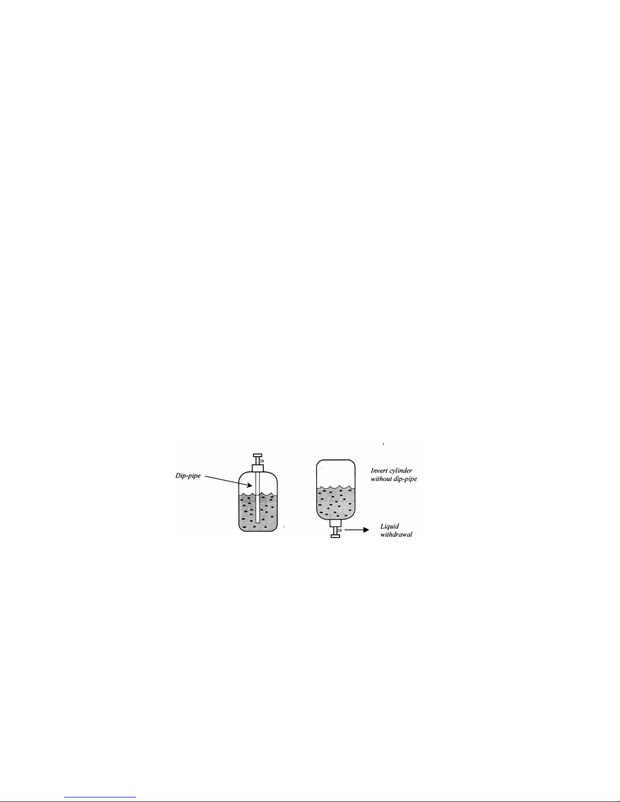
5.5) When charging R407C, ensure that only liquid is being withdrawn from the cylinder or can. This is to ensure
That only the original composition of R407C is being delivered into the system. The liquid composition can be
different from the vapour composition.
Page 23
5.6) Normally, the R407C cylinder or can is being equipped wit h, a dip-pipe for liquid withdrawal. However, if
the dip-pipe is not available, invert the cylinder or can so as to withdraw liquid from the valve at the bottom.
5.7) When servicing leak, the top up method, commonly practice for R22 system, is not recommended for
R407C system, Unlike R22 where t he ref rigerant is of a single component, the composition of R407C, Which madeup of three different component, may have changed during t he leak. Consequently, a top-up may not ensure that the
R407C in the system is of original composition. This composition shift may adversely affect the syst em performance.
It is recommended that the system should be evacuated thoroughly before recharging with R407C.
Page 24
INSTALLATION
The installation shall be m ade by authorized service personnel only.
WARNING
1.For the room air conditioner to operate satisfactorily, install it as outlined in this installation
2.Connect the indoor unit and outdoor unit with the room air conditioner piping and cords available standard p arts. This
installation manual describes the correct connections using the installation set available from our standard part
3. Installation work must be performed in accordance with national wiring standards by authorized service personnel
only
4.Never cut the power cord, lengthen or shorten the cord.
5.Also do not use an extension cord.
6.Do not turn on the power unit all installation work is complete.
!!!!
Is careful not to scratch the room air conditioner when handling it.
!!!!
After installation, explain correct operation to the customer, using the operating manual
!!!!
Let the customer keep this installation manual because it is used when the room air conditioner is service or move
CAUTION
1.Do not install where it is the danger of combustible gas leakage
2.Do not install near heat sources.
3.If children under 10 years old may approach the unit, take preventive measures so that they can not reach the unit
SELECTION OF LOCATION AND SPACE
♦OUTDOOR UNIT
As condensing temperat ure rises, evaporati ng temperature rises and cooling capacity drops. In order to achieve
maximum cooling capacity, the location selected for outdoor unit should fulfill the following requirements:
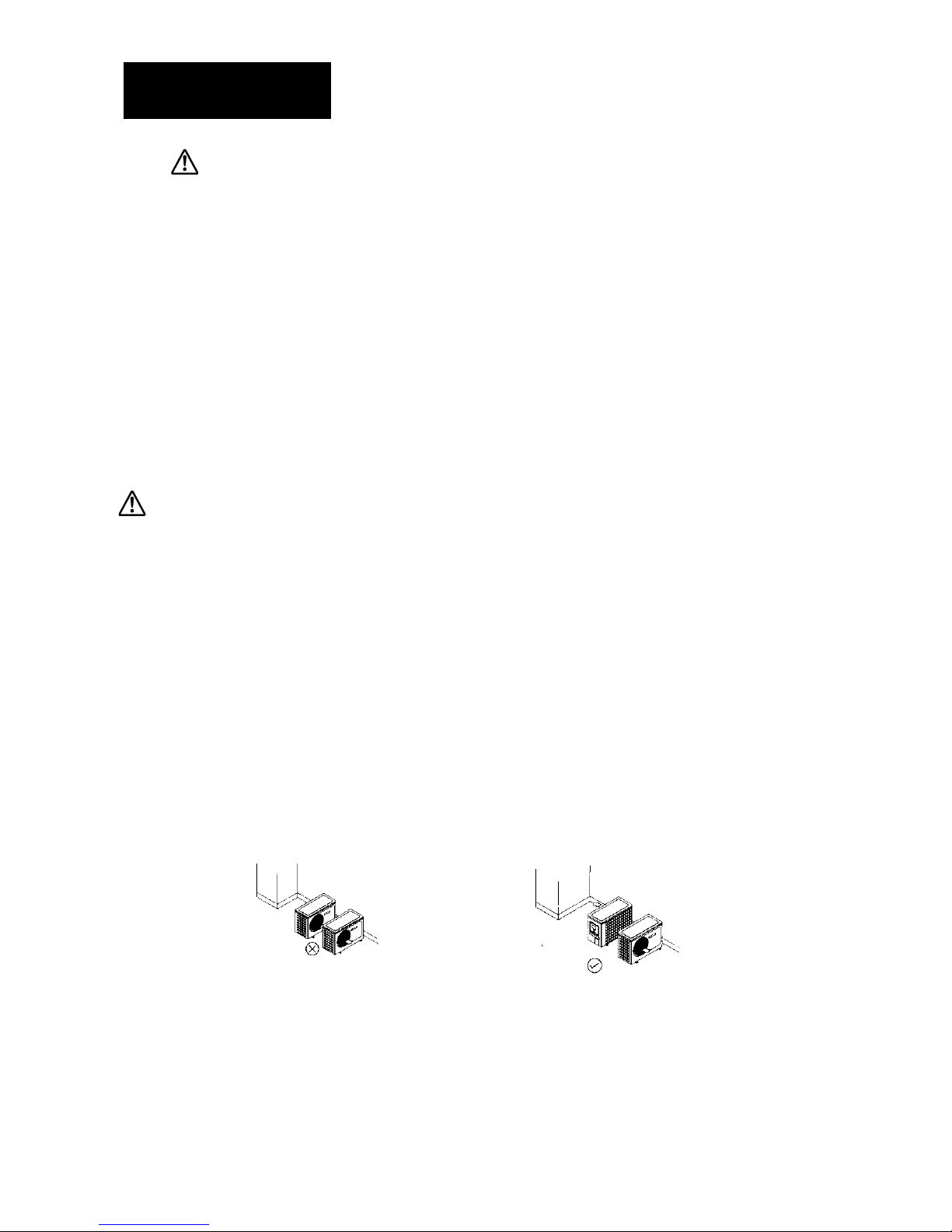
! Install the condensing unit in away such that hot air distributed by the outdoor condensing unit cannot be
drawn in again. Allow suffi cient space for maintenance around the unit.
Page 25
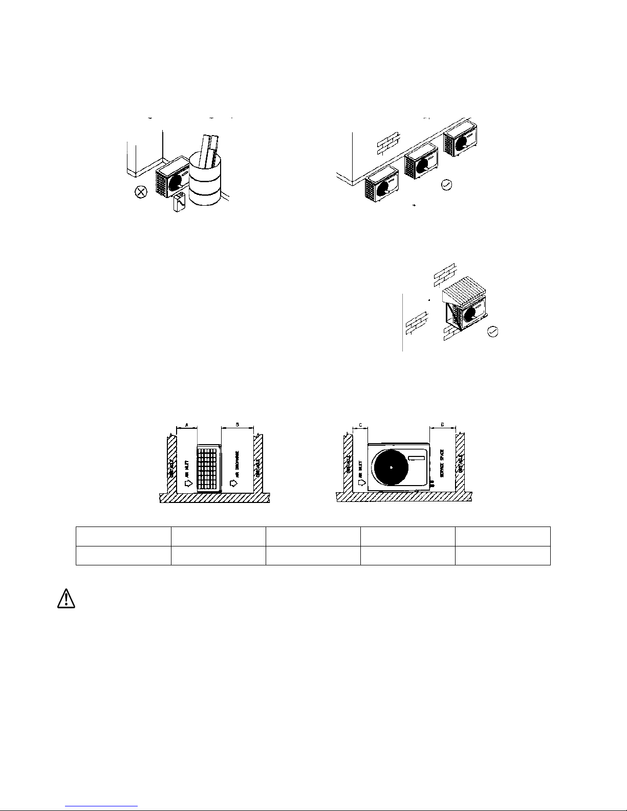
! Ensure that there is no obstruction of airflow int o or out of the unit. Remove obstacles, which block air
intake or discharge
! The location must be well ventilated, so that the unit can draw in and distribute plenty of air thus low ering
the condensing temperature.
! A place capable of bearing t he weight of the outdoor unit and isolating noise and vibration
! A place protected from di rect sunlight. Otherw ise use and awning
for protection, if ne cessary.
! The location must not be susceptible to dust or oil mist.
INSTALLATION CLEARANCE
! Outdoor unit must be ins talled such that there is no shot circuit of
the hot discharge air or obstruction to s m ooth airflow. Select
The coolest possible places where intake air should not be hotter than the outside temp erature.
ALL MODELS A B C D
Minimum Distance 300 mm 1000 mm 300 mm 500 mm
CAUTION
If the condensing unit is operated in an atmosphere containing oils (including machine oils), salt (coastal area), sulphur
gas (near hot spring, oil refinery plant), such substances may lead to failure of the unit.
Page 26
OUTDOOR UNIT INSTALLATION
CAUTION
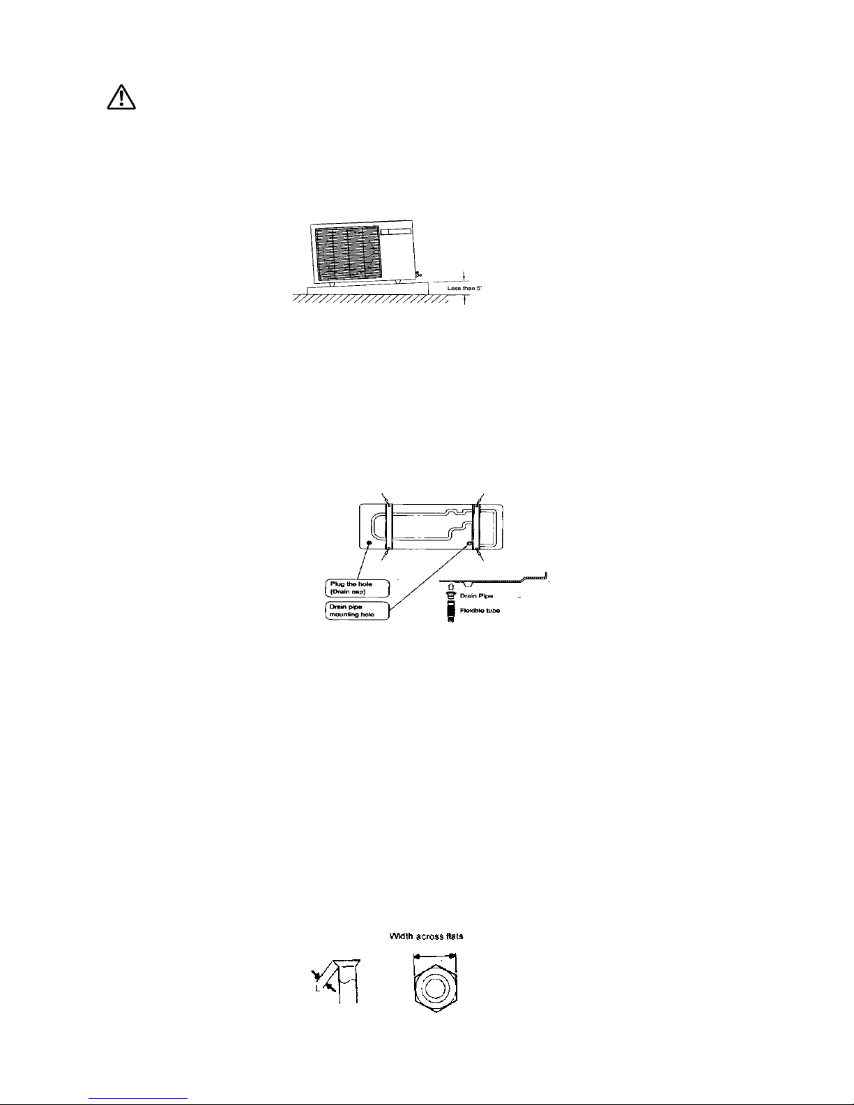
♦♦♦♦ Set the unit on a strong stand, such as on made of concrete blocks.
♦
When the unit is exposed to vibration, install protective rubber pieces under it.
♦
Do not install the unit directly on the ground, because it will cause trouble.
♦
Install the unit where it will not be tilted by more than 5
o
(1) When the outdoor unit will be exposed to strong wind, fasten it with bolts at the places indicated by the
arrow
(2) Since the drain water flows out of the outdoor unit during heatin g operation, install the dr ain pipe and
connect it to a commercial 16 mm hose. (Heat pump model only)
(3) When installing the d rain pipe, plug another hole in the bottom of the outdoor unit with drain cap so there
is no water leakage.
CONNECTING THE PIPING
FLARE PROCESSING
(1) Cut the connection pipe with pipe cutte rs so that the pipe is not deformed.
(2) Holding the pipe dow nward so that cutting can not enter the pipe, remove the burrs.
(3) Remove the flare nut from the indoor unit pipe and outdoor unit, insert the flare nut onto the pipe and flare with
flaring tool.
(4) Check if the flare p art "L" is spread uniformly and that there are no cracks.
Page 27
Model Flare nut width across flats
Liquid Suction
7,000-12,000 Btu/h 17 mm 24 mm
18,000-36,000 Btu/h 21 mm 27 mm
48,000-60,000 Btu/h 24 mm 32 mm
BENDING PIPES
"
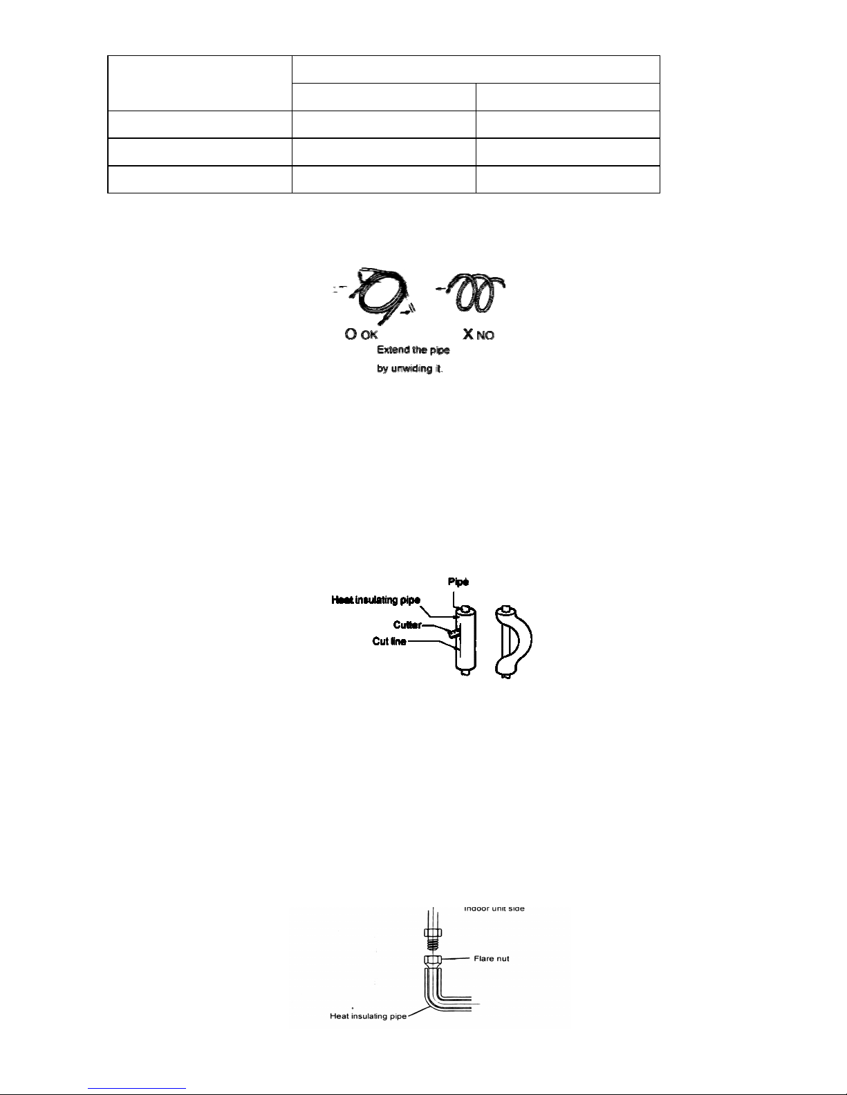
The pipes are shaped by your hands. Be careful n ot to collapse them. Do not bend the pipes in an angle less than
90
o
. When the pipes are bent and stretched repeatedly, the ma terial will be hardened, causing the pipes no longer
be bent or stretched. Be sure to limit number of bending and stretching to three times. When bending the pipe, do
not bend it as is the pipe will be collapsed. In this case, cut the heat insulation pipe with a sharp cutter as shown and
bend it after exposing the pipe. After bending the pipe as you want, be sure to put the heat insulating pipe back on
the pipe and secure it with tape
CONNECTION PIPES
(1) Indoor unit side
♦ Centering the pipe against port on the ind oor unit, turn the flare nut with your hand.
♦ Be sure that the small pipe is c ompletely installed before connecting the large pipe.
Page 28
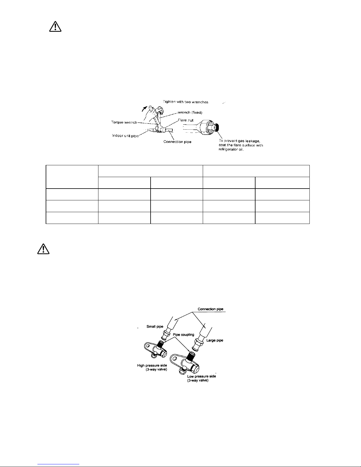
CAUTION
Be sure to apply the pipe against the port on the indoor unit correctly. If the centering is improper the flare nut will not be
tightened smoothly. If the flare nut is forced to turn, threads will be damaged.
When the flare nut is ti ghtened properly by your hand, use a torque wren ch to finally tighten it.
Model Liquid Suction
Pipe size Tightening torque Pipe size Tightening torque
7,000-12,000 Btu/h 1/4"(6.4mm) 6-10 ft-lb.(8-13N.m) 1/2"(12.7mm) 15-25 ft-Ib(20-33N .m)
18,000-36,000 Btu/ h 3/8"(9.5mm) 12-20 ft-lb.(16-27N.m ) 5/8"(15.9mm) 20-30 ft-lb.(27-40N.m)
48,000-60,000 Btu/h 1/2"(12.7mm) 15-25 ft-lb.(20-33N.m) 3/4"(19.0mm) 30-35 ft-lb.(40-47N.m)
Do not remove the cap from the connection pipe before connecting the pipe
CAUTION
Be sure to connect the large pipe after connecting the small pipe completely
(2) Outdoor unit s i de
Tighten the flare nut of the connection pipe at the outdoor unit valve c onnector. The tight ening method is the same as
indoor side
Page 29
CHECKING THE PIPE CONNECTIONS FOR GAS LEAKING
For both the indoor and outdoor unit side, check the joints for gas leaking by the use of a gas leak age detector
without fail when the pipes are connected.
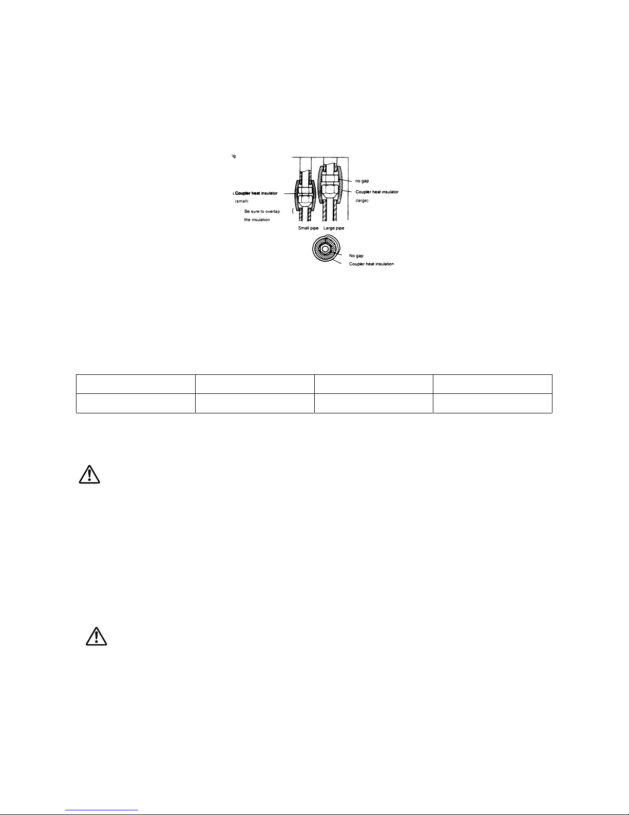
HEAT INSULATION ON THE PIPE JOINTS
Put coupler heat insulator on the joints (indoor side only)
ADDITIONAL CHARGE
Refrigerant suitable for a pipe length of 5 m. is charged in the outdoor unit at the factory. Refrigerant suitable for a
pipe length of 5 m. is charged in t he outdoor unit at the factory. Refrigerant suitable for a pipe length of 5 m. is
charged in the outdoor unit at the factory.
Pipe length 5 m. 7 m. 10 m.
Additional refrigerant None 70 g 175 g
Between 5 m. and 10m., when using a connection pipe other than that in a table, charge additional refrigerant
with 35 g/1m. As the cri teria.
CAUTION
(1)!When moving and installing the air conditioner, do not mix gas other than the specific refrigerant the refrigerant
cycle.
(2) When adding refrigerant, add the refrigerant from the charging port at the completion of work.
(3) The maximum length of the piping is 10 m . If the units are further apart than this, consult manufacture or proper
installation.
GAS LEAKAGE INSPECTION
CAUTION
After the connecting the piping, check the joints for gas leakage with gas leak detector.
.HOW TO CONNECT WIRING TO THE TERMINALS
For solid core wiri ng
(1) Cut the wire with a wire cutter or wire-cutting pliers, then strip the insulation to about
15
/16" (24 mm) of expose t he
the solid wire
(2) Using a screwdriver, remove the terminal screw(s) on the terminal block.
Page 30
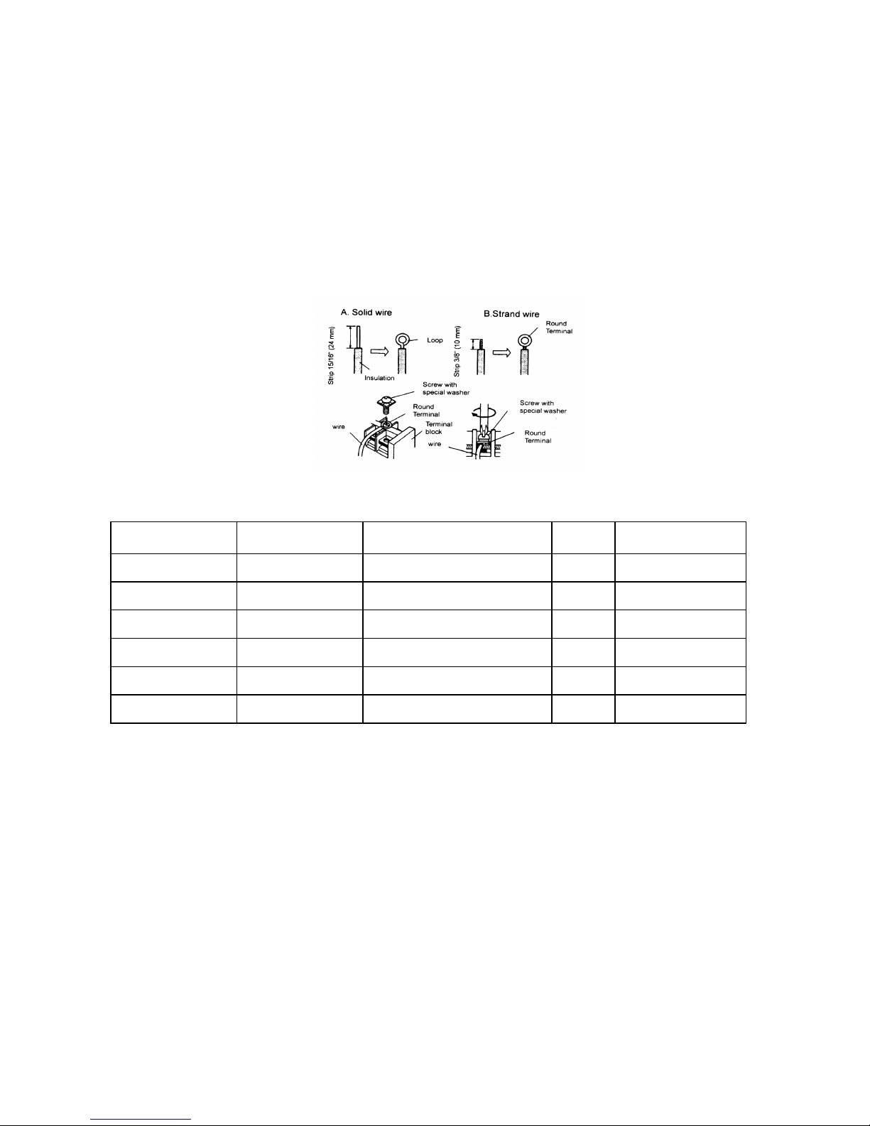
(3) Using pliers, bend the solid wire to form a loop suitable for the terminal screw.
(4) Shape the loop wire p roperly, place it on the terminal block an tighten securely with the terminal screw using a
screwdriver.
For standing wiring
(1) Cut the wire with a wire cutter or wire-cutting pliers, then strip the insulation to about
3
/8"(10mm) of expose t he
stand wiring.
(2)! Using a screwdriver, remove the terminal screw(s) on the terminal block.
(3) Using a round termi nal fastener or pliers, securely clamp a round terminal to each stripp ed wire end.
(4) Position the round terminal wire, replace and tighten terminal screw by using a scr ewdriver.
ELECTRICAL REQUIREMENT
For wire size and fuse t able shows you as followi ng below
Model Supply cord (mm
2
) Indoor to Outdoor cord (mm2) phase Fuse capacity (A)
7,000-12,000 Btu/h 2.5 1.5 1 10
18,000 Btu/h 2.5 1.5 1 15
24,000 Btu/h 4 1.5 1 20
30,000-36,000 Btu/h 6 1.5 1 25
48,000 Btu/h 4 1.5 3 15
56,000-60,000 Btu/h 6 1.5 3 20
Page 31
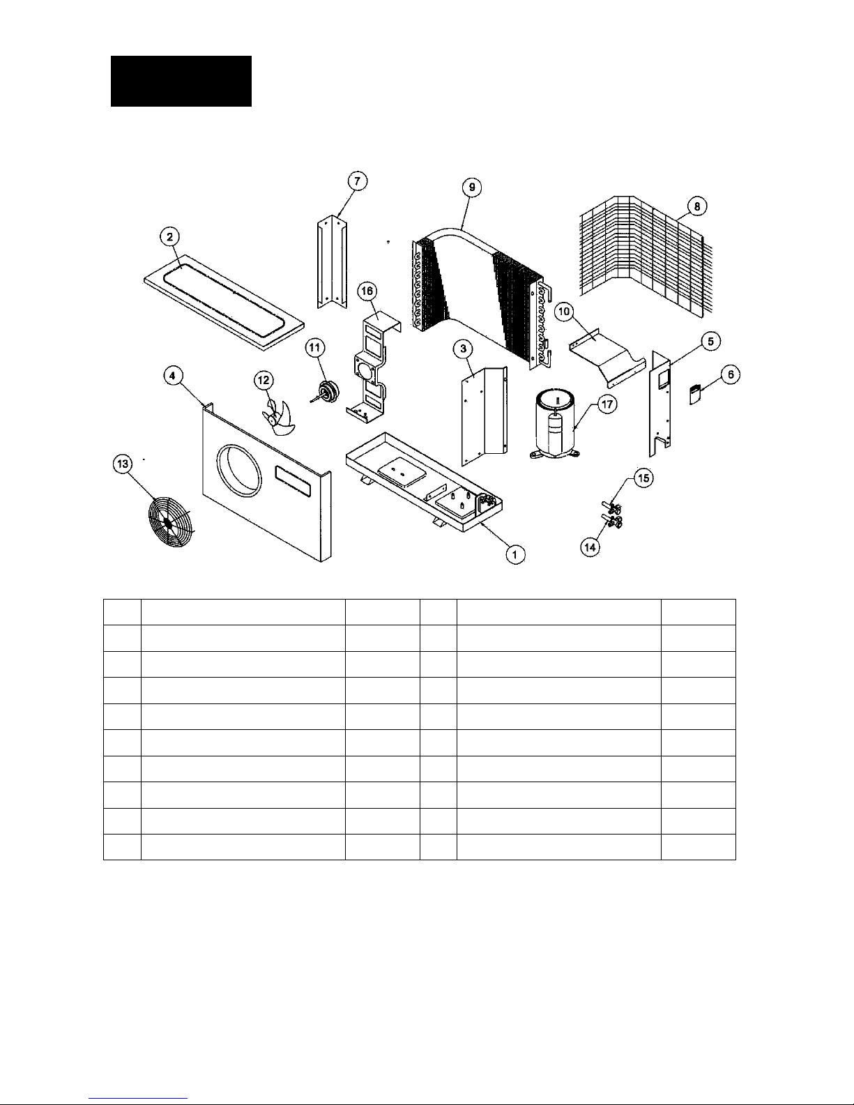
PARTS LIST
MODEL LCU-07, 09, 12
NO PARTS DESCRIPTION Qty. NO PARTS DESCRIPTION Qty.
1 BASE PAN 1 PC 10 FBASE FOR ELEC.PART 1 PC
2 TOP COVER 1 PC 11 FAN MOTOR 1 PC
3 AIR SHIELD PLATE 1 PC 12 PROPELLER 1 PC
4 FRONT PANEL 1 PC 13 FAN GUARD 1 PC
5 BACK PANEL-RIGHT 1 PC 14 SERVICE VALVE-SUCTION 1 PC
6 PLASTIC HANDLE-RIGHT 1 PC 15 SERVICE VALVE-LIQUID 1 PC
7 BACK PANEL-LEFT 1 PC 16 MOTOR BRACKET 1 PC
8 COIL GUARD 1 PC 17 COMPRESSOR 1 SET
9 CONDENSER COIL 1 PC
Page 32
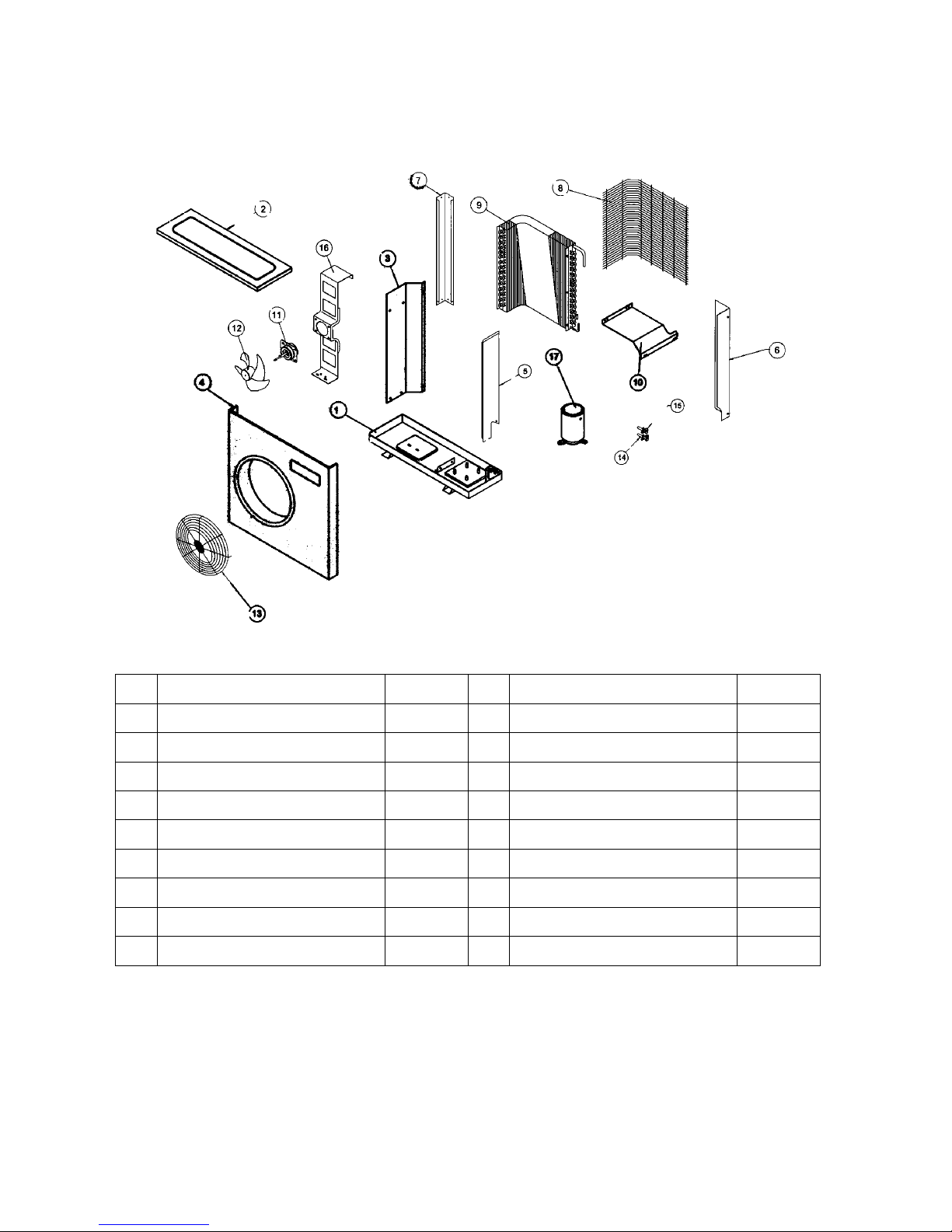
MODEL LCU-18, 24, 30, 36
NO PARTS DESCRIPTION Qty. NO PARTS DESCRIPTION Qty.
1 BASE PAN 1 PC 10 FBASE FOR ELEC.PART 1 PC
2 TOP COVER 1 PC 11 FAN MOTOR 1 PC
3 AIR SHIELD PLATE 1 PC 12 PROPELLER 1 PC
4 FRONT PANEL 1 PC 13 FAN GUARD 1 PC
5 BACK PANEL-RIGHT 1 PC 14 SERVICE VALVE-SUCTION 1 PC
6 PLASTIC HANDLE-RIGHT 1 PC 15 SERVICE VALVE-LIQUID 1 PC
7 BACK PANEL-LEFT 1 PC 16 MOTOR BRACKET 1 PC
8 COIL GUARD 1 PC 17 COMPRESSOR 1 SET
9 CONDENSER COIL 1 PC
Page 33
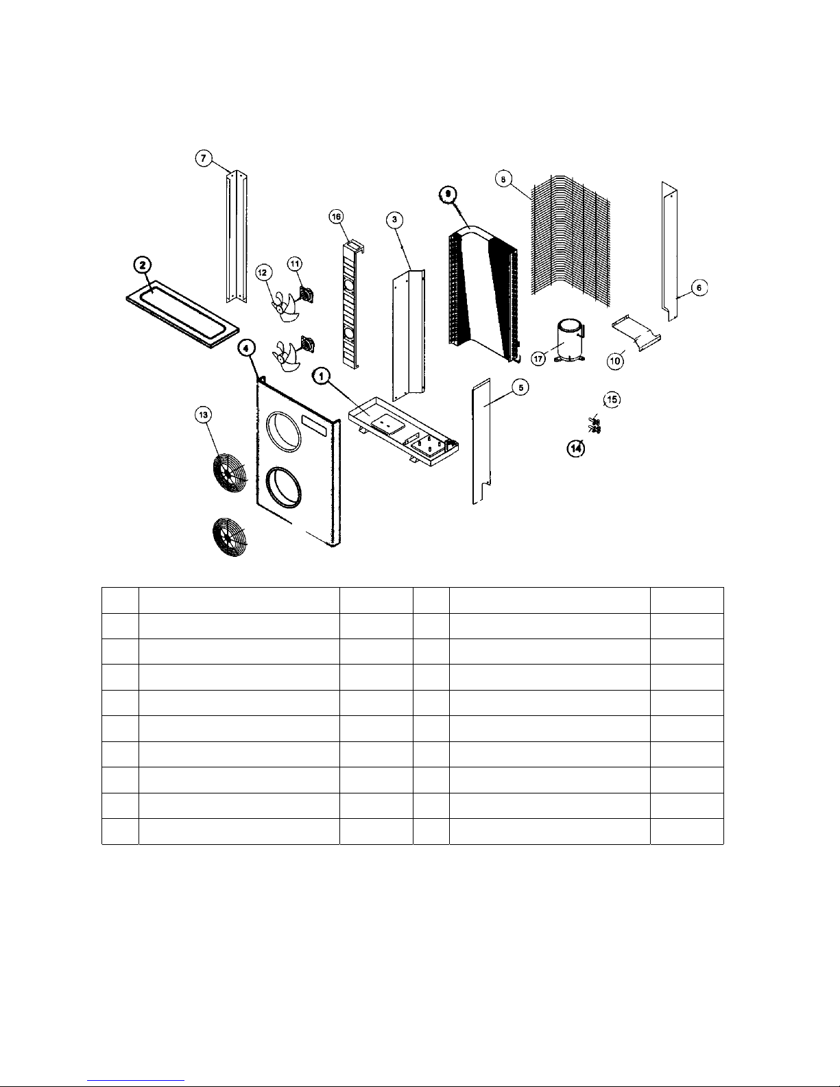
MODEL LCU-48, 56, 60
NO PARTS DESCRIPTION Qty. NO PARTS DESCRIPTION Qty.
1 BASE PAN 1 PC 10 FBASE FOR ELEC.PART 1 PC
2 TOP COVER 1 PC 11 FAN MOTOR 2 PCS
3 AIR SHIELD PLATE 1 PC 12 PROPELLER 2 PCS
4 FRONT PANEL 1 PC 13 FAN GUARD 2 PCS
5 SIDE PANEL 1 PC 14 SERVICE VALVE-SUCTION 1 PC
6 BACK PANEL-RIGHT 1 PC 15 SERVICE VALVE-LIQUID 1 PC
7 BACK PANEL-LEFT 1 PC 16 MOTOR BRACKET 1 PC
8 COIL GUARD 1 PC 17 COMPRESSOR 1 SET
9 CONDENSER COIL 1 PC
Page 34
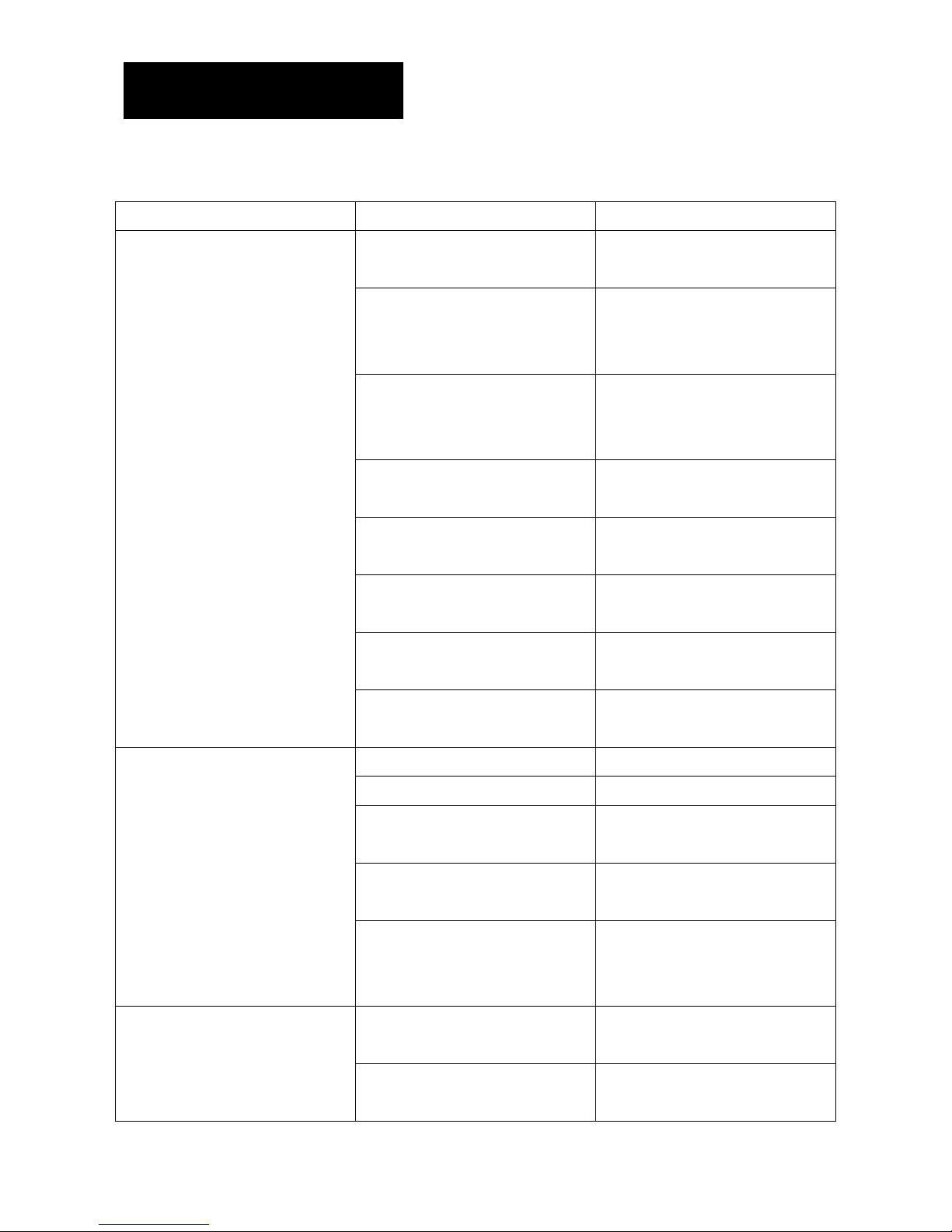
TROUBLESHOOTING
When any air-conditio ner malfunction is noted, immediately switch off the power supply to the unit,
and contact the local dealer, if necessary. Some simple troublesho oting tips are given below.
PROBLEM POSSIBLE CAUSE TO CORRECT
Low voltage Check for voltage at compressor.
Will operate at 10% voltage variance.
Thermostat not set cold enough or
inoperative.
Set thermostat to coldest position.
Test thermostat and r eplace if
inoperative.
Compressor hums but cuts off on
overload
Hard start compressor. Direct test
compressor. If compressor starts,
add starting compon ents.
Open or shorted compressor
windings.
Check for continuity and resistance.
Open overload. Tests overload prot ector and replace
if inoperative.
Open capacitor. Test capacitor and replace if
inoperative.
Inoperative system swit ch Test for continuity in all positions.
Replace if inoperative
Compressor does not run
Broken, loose or incorrect wiring. Refer to appropriate wiring diagram
to check wiring.
Inoperative system swit ch. Test switch and replace if inoperative
Broken, loose or incorrect wiring. Refer to applicable wiring diagram.
Open capacitor Test capacitor and replace if
inoperative.
Fan speed switch open. Tests switch and replace if
inoperative.
Fan motor does not r un.
Inoperative fan motor Test fan motor and replace if
inoperative(be sure internal overload
has had time to reset)
Dirty or plugged cond enser or
evaporator coil.
Use steam or detergent to clean.
Does not cool, or cools only slightly.
Poor air circulation in area being
cooled.
Adjust discharge air louvers. Use
high fan speed.
Page 35

PROBLEM POSSIBLE CAUSE TO CORRECT
Fresh air or exhaus t air door opens
on applicable models.
Close doors. Inst ruct customer on
use of this feature.
Low capacity-undercharge. Check for leak and make repair.
Does not cool, or cools only slightly.
Compressor not pumpi ng properly. Check amperage draw against
nameplate. If not con clusive. Make
pressure test.
Fuse blown or circuit tripped. Replace fuse, res et breaker. If
repeats check fuse or breaker size.
Check for shorts in unit wiring and
components.
System switch in OFF posit ion. Set switch correctly.
Inoperative system switch. Test for continuity in ea ch s witch
position.
Unit does not run
Loose or disconnected wiring at
switch or other components
Check wiring and connections.
Reconnect per wiri ng diagram.
Poorly installed unit. Refer to Installation instruction for
proper installation.
Fan blade-striking chassis. Reposi tion-adjust motor mount.
Compressor vibrating. Check that c ompressor grommets
have not deteriorat ed.
Check that compr essor mounting
parts are not missing
Noisy operation
Improperly mounted or loose cabinet
parts.
Check assembly and parts for
looseness rubbing and rattling.
Loss of charge in thermostat bulb. Place jumper across thermostat
terminals to check if unit operates. If
unit operates replace thermostat.
Loose or broken part s in thermostat Check as above.
Thermostat does not turn unit on.
Incorrect wiring. Refer to appropriate wiring diagram.
Page 36
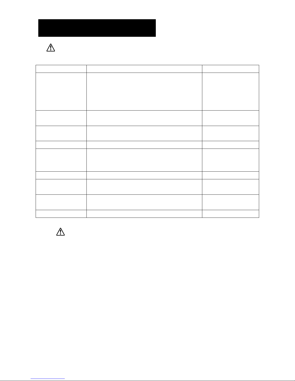
SERVICE AND MAINTENACE
CAUTION
Before cleaning the air conditioner be sure to turn it off and turn off the circuit breaker.
Components Maintenance Procedure Recommended Schedule
Air Filter (indoor Unit) 1.!Remove the filter from unit before cleaning the filter
2. Remove the dust on the filter by using a vacuum cleaner or wash
wash using water less than 40oC with a neutral
3. Rinse and dry it before fitting back the filter and set it back to unit
4. Note : Never use petrol, thinner, benzene or any other chemicals.
At least once a month.
Indoor unit 1. Clean away dirt or dust on grille or panel by w iping with a soft cloth
soaked in (or cool) water or neutral detergent solution
At least once a 3 month.
Condense Drain Pan & Pipe 1. Check the cleanliness and clean it if necessary
2. Check the condense water flow
Every 3 months.
Indoor Fan Check if there is any abnormal noise. if necessary
Indoor/Outdoor Coil 1. Check and remove the dirt between the fins.
2. Check and remove any obstacles which ginder air flow through the
indoor or outdoor.
Every month.
Power Supply Check the running current and voltage for indoor and outdoor unit Every 2 months Every year
Compressor No maintenance needed if refrigerant circuit remains sealed.
However, check for refrigerant leak at joint and fitting.
Every 6 months
Compressor Oil Oil is factory charged. Not necessary to add oil if circuit remains
sealed.
No maintenance required
Fan Motor Oil All motor are pre-lubricated and sealed at factory No maintenance required
WARNING
Do not charge OXYGEN, ACETYLENE OR OTHE R FLAMMABLE and poisonous gases into the unit when Performing
a leakage test or an airtight test. These gases could cause severs explosion and damage if Exposed to high temperature and
pressure. It is recommended that only nitrogen or refrigerant be charge When performing the leakage test or airtight test.
 Loading...