

Page 1
1
“PH CONTROLLER”
OPERATING MANUAL
Read carefully! ENGLISH Version
R1-10-02
This manual contains important safety informations about
installation and use of this equipment. Ignoring this
informations could result in injuries or damages.
It is strictly forbidden to use this equipment with
radioactive chemicals !
Page 2
2
“pH Controller” series instruments comply with the following European
regulations:
EN60335-1 : 1995, EN55014, EN50081-1/2, EN50082-1/2, EN6055-2,
EN60555,3
Based on directive CEE 73/23 c 93/68 (DBT Low voltage directive) and
directive 89/336/CEE (EMC Electromagnetic Compatibility)
Danger!
GENERAL SAFETY GUIDELINES
In emergencies the instrument should be switched off immediately! Disconnect the
power cable from the power supply!
When using instrument with aggressive chemicals observe the regulations
concerning the transport and storage of aggressive fluids!
When installing outside European Community, always observe national regulations!
Manufacturer is not liable for any unauthorized use or misuse of this product that
can cause injury or damage to persons or materials!
Caution!
Instrument must be accessible at all times for both operating and servicing. Access
must not be obstructed in any way!
Feeder should be interlocked with a no-flow-protection device.
Instrument and accessories must be serviced and repaired by qualified and
authorised personnel only!
Always read chemical safety datasheet!
Always wear protective clothing when handling hazardous or unknown chemicals!
Page 3

3
Index
GENERAL DESCRIPTION 4
CONTROL PANEL 4
MENU / FUNCTIONS 5
INSTRUMENT CALIBRATION 5
INSTRUMENT MESSAGES 5
FUSE REPLACEMENT 6
PERISTALTIC PUMP INTERNAL HOSE 6
ON/OFF INSTRUMENT 6
pH INSTRUMENT INSTALLATION DRAWING 7
Page 4

4
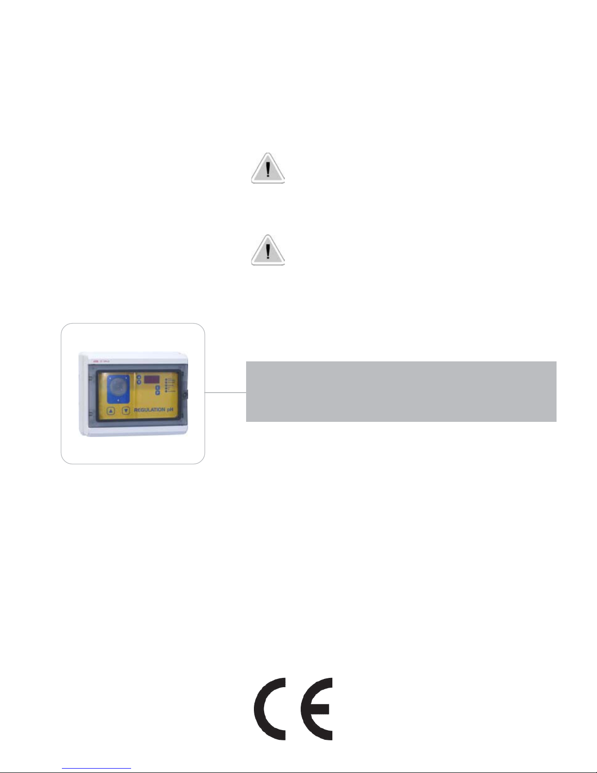
GENERAL DESCRIPTION
“pH Controller” measures and controls swimming pools pH and it doses the chemical by an internal
peristaltic pump. The reading values are shown on a 3 units high luminosity display. The instrument
is cased into a plastic casing box (IP65) for wall mounting. Overall dimensions are 275x220x140mm.
CONTROL PANEL
Use “UP” and “DOWN” keys to select or to increase/decrease set values.
The “Enter” key confirms your choice (when this function is selected the led is on).
“ESC” key deletes the selection and returns to previous menu.
If you will use default values, confirm it by pressing “E”.
Introduction
Suction Hose:
to the chemical
Delivery
Hose:
to the swimmingpool/Plant
Peristaltic
Capacity: 2,2 l/h
“UP” and “DOWN” Keys
for programming
3 Digits Display
Selected
Function
Programming mode
key
Enter
Key
Page 5

5
Programming the instrument
MENU / FUNCTIONS
To entering into “Selected function” keep pressed “P” key until the first green led will light on.
By pressing “P” key more times it is possible to verify/set the instrument functions. The
selected function is showed by the green led near the function menu. TO GO BACK TO THE
NORMAL OPERATING MODE PRESS “P” MORE TIMES UNTIL THE GREEN LED IS OFF.
“Point Consigne”: pH SetPoint. pH that the instrument aims to reach during the dosage. If the pH
value is close to the setted value, the peristaltic pump will not start working. If the pH value is different,
the peristaltic pump will dose proportionally until its maximum capacity (100%). We recommend to
set the “Point Consigne” between 7.2 and 7.4 (optimum pH value for swimming pool). Press “E” to
confirm. Press another key to exit from the menu.
“Securitè”: maximum time, in minutes, available to the instrument to reach the pH restoration, as set
in the “Point Consigne”. If the instrument does not reach this pH value during the maximum time, it
will enter in alarm mode (blinking display) and will stop the peristaltic pump functioning. Press “E” to
confirm. Press another key to exit from the menu.
“Manuel”: manual working mode of the peristaltic pump for a settable time (minutes, seconds) by
using “UP” and “DOWN” keys. Press “E” to confirm and wait a second before the pump starts
working. The display will show the remaining working time. At the end (display “000”) th instrument
will stop the dosage. To repeat another manual dosing cycle press “E” key, press “P” to exit from the
menu and cancel the operation.
“pH+”, “pH-”: chemical type used to restore the swimming pool pH value. Set on “bAS”, by “UP”
and “DOWN” keys, if using a “pH+” chemical. Set on “ACd” if using a “pH-” chemical. Press “E” to
confirm. Press another key to exit from the menu.
“Calibrage”: buffer solution value used for calibration. We recommend to use a “7pH” solution. See
next paragraph for calibration mode.
INSTRUMENT CALIBRATION
Prepare the buffer solution and the pH probe before enter into the calibration menu.
Connect pH probe to the instrument by the BNC connection. Remove the probe from the probe
holder and put it into the buffer solution. Wait until read value is stable, keep pressed the “P” key until
the first green led will light on. Leave the “P” key. Press “P” key 4 times: the green led near
“CALIBRAGE” function will light on. Use “UP” and “DOWN” keys to enter the buffer solution value
and press “E” to confirm. The value shown on the display is not the probe value but it is the
buffer solution value. So, it may not reach the buffer solution value.
INSTRUMENT MESSAGES
“DEF”: restore instrument default values. It may be operated by the user. Disconnect the instrument
from power supply, press “UP” and “DOWN” keys together then connect power supply again.
Release the “UP” and “DOWN” keys.
“PHL” o “PHH”: pH reading value out of range (not from 0 to 14pH).
Page 6

6
Maintenance
FUSE REPLACEMENT
The following operation must be performed by qualified personnel only.
The instrument must be unplugged from the power supply.
Remove the four screws at the corners of the panel. Locate the fuse holder (as shown on figure).
Remove the protective cap and replace the fuse with one of the same features (250V T315mA 5x20).
PERISTALTIC PUMP INTERNAL HOSE REPLACEMENT
Once a year or each 300 working hour replace the internal hose of the peristaltic pump.
ON/OFF INSTRUMENT
Keep pressed “E” key for about three seconds: the instrument will be on/off.
Page 7

7
1 - Injection valve
2 - Sampling point
3 - pH probe
4 - Probe holder
5 - pH instrument
7 - Foot filter
8 - Power cable
9 - Safety breaker
10 - Filter
11 - Delivery hose
12 - Suction hose
9
5
3
1
2
7
4
8
10
11
12
pH instrument installation drawing
Page 8

8
When dismantling an instrument please separate material types and send them according to local recycling disposal requirements. We
appreciate your efforts in supporting your local Recycle Environmental Program.
Working together we’ll form an active union to assure the world’s invaluable resources are conserved.
 Loading...