

Emec MTOWER PLUS Series, MTOWER PLUS CD, MTOWER PLUS RH, MTOWER PLUS PH Operating Instructions Manual
Page 1
This manual contains safety information that if ignored
can endanger life or result in serious injury. They are
indicated by this icon.
Keep the instrument protected from sun and water.
Avoid water splashes.
OPERATING INSTRUCTIONS FO R
“MTOWER PLUS” INSTRUMENT
CD/PH/RH Version
Read Carefully !
1
ENGLISH Version
R12-01-18
Page 2

NORME CE
EC RULES(STANDARD EC)
NORMAS DE LA CE
Direttiva Bassa Tensione
Low Voltage Directive
Directiva de baja tensión
Direttiva EMC Compatibilità Elettromagnetica
EMC electromagnetic compatibility directive
EMC directiva de compatibilidad electromagnética
2014/35/UE
⎬
GENERAL SAFETY GUIDELINES
2014/30/UE
⎬
Danger!
Caution!
2
In emergencies the instrument should be switched off immediately! Disconnect the power cable
from the power supply!
When installing always observe local regulations!
Manufacturer is not liable for any unauthorized use or misuse of this product that may cause injury,
damage to persons and / or materials.
Instrument must be accessible at all times for both operating and servicing. Access must not be
obstructed in any way!
Feeder should be interlocked with a no-flow protection device to automatically shut-off the pumps
when there is no flow!
Pumps and accessories must be serviced and repaired by qualified and authorized personnel only!
Always discharge the liquid end before servicing the instrument!
Empty and rinse the liquid end before work on a pump which has been used with hazardous or
unknown chemicals!
Always read chemical safety datasheet!
Always wear protective clothing when handling hazardous or unknown chemicals!
Instrument must be operated / serviced by trained technicians only!
All connection operations must be performed while the instrument is not connected to main
supply!
Page 3

Introduction.
The “MTOWER PLUS” is a fully featured cooling towers controller with two-way biocide options and inhibitor / bleed
control.Cooling towers are heat removal devices used to transfer process waste heat to the atmosphere. Cooling towers
may either use the evaporation of water to remove process heat and cool the working uid to near the wet-bulb air
temperature or rely solely on air to cool the working uid to near the dry-bulb air temperature. Common applications
include cooling the circulating water used in oil reneries, chemical plants, power plants and building cooling.
All information is provided through a large backlit LCD display (240x64). Using a revolutionary wheel control the instrument
can be easily programmed. “MTOWER PLUS” is housed in a IP65 plastic box.
Measures are: L325 x H235 x D125 (including wheel and connectors).
Main features of “MTOWER PLUS” are:
BLEED
(Feed&Bleed, Feed&Bleed Percentual , PercenutalTime, WaterMeter, WaterMeter PPM)
Conductivity, pH and ORP Meter with Proportional and Digital outputs
INHIBITOR with 5 working modes
BIOCIDE with weekly program
The wheel.
Located in the upper right side of “MTOWER PLUS” there is a wheel used to control the instrument.
Wheel can be rotated in both directions to scroll over menus and / or pressed to conrm highlighted selection / value.
- Edit single eld submenu by pressing wheel twice.
- When in main screen keep wheel pressed to switch “OFF” instrument. Repeat procedure to switch “ON” instrument.
Rotate the wheel to cycle-loop
through all available options.
Clockwise or Counterclockwise.
Press wheel to move
on submenu for selected option.
3
Page 4

Mainboard Connections.
Unplug instrument from main power supply then perform connections to probes and / or selected outputs by following
the above picture. For easy understanding board has been divided into two parts: Power connections and I/O
connections.
CD Module
L 1 2 3 4 5 6
E E E E E E E
F1
N N N N N N N N
F2
A B
7 8 9 10 11 12
]
Power Connections
Power Connections:
F1: General fuse (6.3AT)
F2: Circuit fuse (3.15AT)
Main power supply (from 90VAC to 265VAC):
L (live), E (earth), N(neutral)
Setpoint Outputs
(voltage output is the same as for main power supply):
1 - E - N (F1 fuse protected) D1 pH
2 - E - N (F1 fuse protected) Inhibitor
3 - E - N (F1 fuse protected) D1 mV (Biocide 1)
4 - E - N (F1 fuse protected) Biocide 2
5 - E - N (F1 fuse protected) Pre-biocide 1
6 - E - N (F1 fuse protected) Pre-biocide 2
1 2 3 4 5 6 7 8 9 10 11 12 13 14 15 16 17 18 19 20 21 22 23 24 25 26 27 28
29 30 31 32 33 34 35 36 37 38 39 40 41 42 43 44 45 46 47 48 49 50 51 52 53 54 55 56
]
I/O Connections
pH
Module
ORP
Module
Bleed Valve (Free Voltage Version): 7(N.C.), 8(C), 9(N.O.) Free Voltage contact
General Alarm output: 10(N.C.), 11(C), 12(N.O.) Free Voltage contact
Warning: Connections must be perfomed by qualied and trained personnel only.
4
Page 5

I/O Connections:
Standby / Proportional Outputs: 1: - D1 mV (Biocide1) 3: - Biocide2 5: - Pre-biocide1 7: - (Cl) 9: - pH 11: - Inhibitor
2 + D1 mV (Biocide1) 4: + Biocide2 6: + Pre-biocide1 8: + (Cl) 10: + pH 12: + Inhibitor
mA outputs (500 Ohm max resistive load): 13: Common
STANDBY OUT (1-6) PROPORTIONAL OUT (7-12)
14: mA output 1 (conductivity)
15: mA output 2 (temperature)
GND shared!
16: mA output 3 (pH)
17: mA output 4 (mV)
RS485:
26: + Signal RS485 (A)
27: - Signal RS485 (B)
GNS shared!
Tank Level inputs: 29 (-) ; 30 (+) mV Level
31 (-) ; 32 (+) Biocide 2 Level
33 (-) ; 34 (+) Pre-biocide 1 Level
35(-) ; 36(+) Pre-biocide 2 Level
37 (-) ; 38 (+) Inhibitor Level
(-) GND shaerd
54 (+) ; 55(-) pH Level
FLOW sensor (mod. “SEPR”) input: 39(+ Brown) ; 40(Black) ; 41(- Blue)
41 shortcut with block n.37
OPTIONS
MANIFOLD input: 39(White) ; 40(Black)
41 shortcut with block n.37
(Hall effect) pulse sender water meter (makeup water): 42(+12VDC) ; 43(INPUT) ; 44(GND)
(Contact) Pulse sender water meter (makeup water): 43(INPUT) ; 44(GND)
(Hall effect) Pulse sender water meter (bleed water): 45(+12VDC) ; 46(INPUT) ; 47(GND)
(Contact) Pulse sender water meter (bleed water): 46(INPUT) ; 47(GND)
Temperature Probe input (mod. “ETEPT”): 50(green) ; 51(brown) ; 52(white) ; 53(yellow)
OPTIONS
OPTIONS
(remove resistance before to install probe)
5
Page 6

Cooling tower basic knowledge.
What is a (wet, atmospheric) cooling tower?
A cooling tower is a heat rejection device, which extracts waste heat to the atmosphere though the cooling of a water
stream to a lower temperature. The type of heat rejection in a cooling tower is termed “evaporative” in that it allows a small
portion of the water being cooled to evaporate into a moving air stream to provide signicant cooling to the rest of that
water stream. The heat from the water stream transferred to the air stream raises the air’s temperature and its relative
humidity to 100%, and this air is discharged to the atmosphere. Evaporative heat rejection devices such as cooling towers
are commonly used to provide signicantly lower water temperatures than achievable with “air cooled” or “dry” heat rejection devices, like the radiator in a car, thereby achieving more cost-effective and energy efcient operation of systems in
need of cooling. Think of the times you’ve seen something hot be rapidly cooled by putting water on it, which evaporates,
cooling rapidly, such as an overheated car radiator. The cooling potential of a wet surface is much better than a dry one.
Common applications for cooling towers are providing cooled water for air-conditioning, manufacturing and electric power
generation. The smallest cooling towers are designed to handle water streams of only a few gallons of water per minute
supplied in small pipes like those might see in a residence, while the largest cool hundreds of thousands of gallons per
minute supplied in pipes as much as 15 feet (about 5 meters) in diameter on a large power plant.
The generic term “cooling tower” is used to describe both direct (open circuit) and indirect (closed circuit) heat rejection
equipment. While most think of a “cooling tower” as an open direct contact heat rejection device, the indirect cooling
tower, sometimes referred to as a “closed circuit cooling tower” is nonetheless also a cooling tower.
A direct, or open circuit cooling tower is an enclosed structure with internal means to distribute the warm water fed to
it over a labyrinth-like packing or “ll.” The ll provides a vastly expanded air-water interface for heating of the air and
evaporation to take place. The water is cooled as it descends through the ll by gravity while in direct contact with air that
passes over it. The cooled water is then collected in a cold water basin below the ll from which it is pumped back through
the process to absorb more heat. The heated and moisture laden air leaving the ll is discharged to the atmosphere at a
point remote enough from the air inlets to prevent its being drawn back into the cooling tower.
The ll may consist of multiple, mainly vertical, wetted surfaces upon which a thin lm of water spreads (lm ll), or several
levels of horizontal splash elements which create a cascade of many small droplets that have a large combined surface
area (splash ll).
An indirect, or closed circuit cooling tower involves no direct contact of the air and the uid, usually water or a glycol
mixture, being cooled. Unlike the open cooling tower, the indirect cooling tower has two separate uid circuits. One is
an external circuit in which water is recirculated on the outside of the second circuit, which is tube bundles (closed coils)
which are connected to the process for the hot uid being cooled and returned in a closed circuit. Air is drawn through the
recirculating water cascading over the outside of the hot tubes, providing evaporative cooling similar to an open cooling
tower. In operation the heat ows from the internal uid circuit, through the tube walls of the coils, to the external circuit
and then by heating of the air and evaporation of some of the water, to the atmosphere. Operation of the indirect cooling
towers is therefore very similar to the open cooling tower with one exception. The process uid being cooled is contained
in a “closed” circuit and is not directly exposed to the atmosphere or the recirculated external water.
In a counter-ow cooling tower air travels upward through the ll or tube bundles, opposite to the downward motion of the
water. In a cross-ow cooling tower air moves horizontally through the ll as the water moves downward.
Cooling towers are also characterized by the means by which air is moved. Mechanical-draft cooling towers rely on
power-driven fans to draw or force the air through the tower. Natural-draft cooling towers use the buoyancy of the exhaust
air rising in a tall chimney to provide the draft. A fan-assisted natural-draft cooling tower employs mechanical draft to
augment the buoyancy effect. Many early cooling towers relied only on prevailing wind to generate the draft of air.
6
Page 7

Cooling tower basic knowledge.
If cooled water is returned from the cooling tower to be reused, some water must be added to replace, or make-up, the
portion of the ow that evaporates. Because evaporation consists of pure water, the concentration of dissolved minerals
and other solids in circulating water will tend to increase unless some means of dissolved-solids control, such as blowdown, is provided. Some water is also lost by droplets being carried out with the exhaust air (drift), but this is typically
reduced to a very small amount by installing bafe-like devices, called drift eliminators, to collect the droplets. The makeup amount must equal the total of the evaporation, blow-down, drift, and other water losses such as wind blowout and
leakage, to maintain a steady water level.
Some useful terms, commonly used in the cooling tower industry:
Drift - Water droplets that are carried out of the cooling tower with the exhaust air. Drift droplets have the same concen-
tration of impurities as the water entering the tower. The drift rate is typically reduced by employing bafe-like devices,
called drift eliminators, through which the air must travel after leaving the ll and spray zones of the tower.
Blow-out - Water droplets blown out of the cooling tower by wind, generally at the air inlet openings. Water may also
be lost, in the absence of wind, through splashing or misting. Devices such as wind screens, louvers, splash deectors
and water diverters are used to limit these losses.
Plume - The stream of saturated exhaust air leaving the cooling tower. The plume is visible when water vapor it
contains condenses in contact with cooler ambient air, like the saturated air in one’s breath fogs on a cold day. Under
certain conditions, a cooling tower plume may present fogging or icing hazards to its surroundings. Note that the water
evaporated in the cooling process is “pure” water, in contrast to the very small percentage of drift droplets or water blown
out of the air inlets.
Blow-down - The portion of the circulating water ow that is removed in order to maintain the amount of dissolved
solids and other impurities at an acceptable level.
Leaching - The loss of wood preservative chemicals by the washing action of the water owing through a wood struc-
ture cooling tower.
Noise - Sound energy emitted by a cooling tower and heard (recorded) at a given distance and direction. The sound is
generated by the impact of falling water, by the movement of air by fans, the fan blades moving in the structure, and the
motors, gearboxes or drive belts.
7
Page 8

“MTOWER PLUS” basic treatments.
“MTOWER PLUS” basically operates three main treatments to grant cooling efciency: inhibitor, bleed and biocide.
What is the purpose of inhibitor ?
Inhibitor is a chemical compound that, when added to water, decreases the corrosion rate of a metal or an alloy. It
prevents cooling tower plant to mantain hoses efciency in water circulating system.
To set:
Working Mode
To setup and congure this function see page 22.
What does it mean bleed ?
A method for controlling the amount and concentration of make-up water and chemicals introduced into the recirculating
water of a cooling tower system. A oat operated make-up valve controls the addition of make-up water to the tower. As
make-up water is added to the tower a vacuum is produced at an injector valve which draws chemicals from a chemical
holding tank into the make-up water, thereby allowing precise control of the chemical concentration in the make-up liquid.
Further, a bleed valve is provided which is responsive to the vacuum produced at the injector valve and bleeds a portion
of the recirculating water to waste.
To set:
Setpoint
Dead band
Time Limit
To setup and congure this function see page 24.
What is a biocide ?
A biocide is a chemical substance capable of killing living organisms, usually in a selective way. They prevent the fouling
of cooling tower water. Cooling tower users frequently apply biocides to the circulating cooling water to control growth
of microorganisms, algae, and macroorganisms. Another very important reason for using biocides in cooling towers is
to prevent the growth of Legionella, including species that cause legionellosis or Legionnaires’ disease, most notably L.
pneumophila. “MTOWER PLUS” can be set to perform also a pre-biocide (biocide activator or pre biocide treatment)
activity.
To set:
Pre-bleed
Pre-biocide
Biocide
Lockout
Week
To setup and congure this function see page 23.
8
Page 9
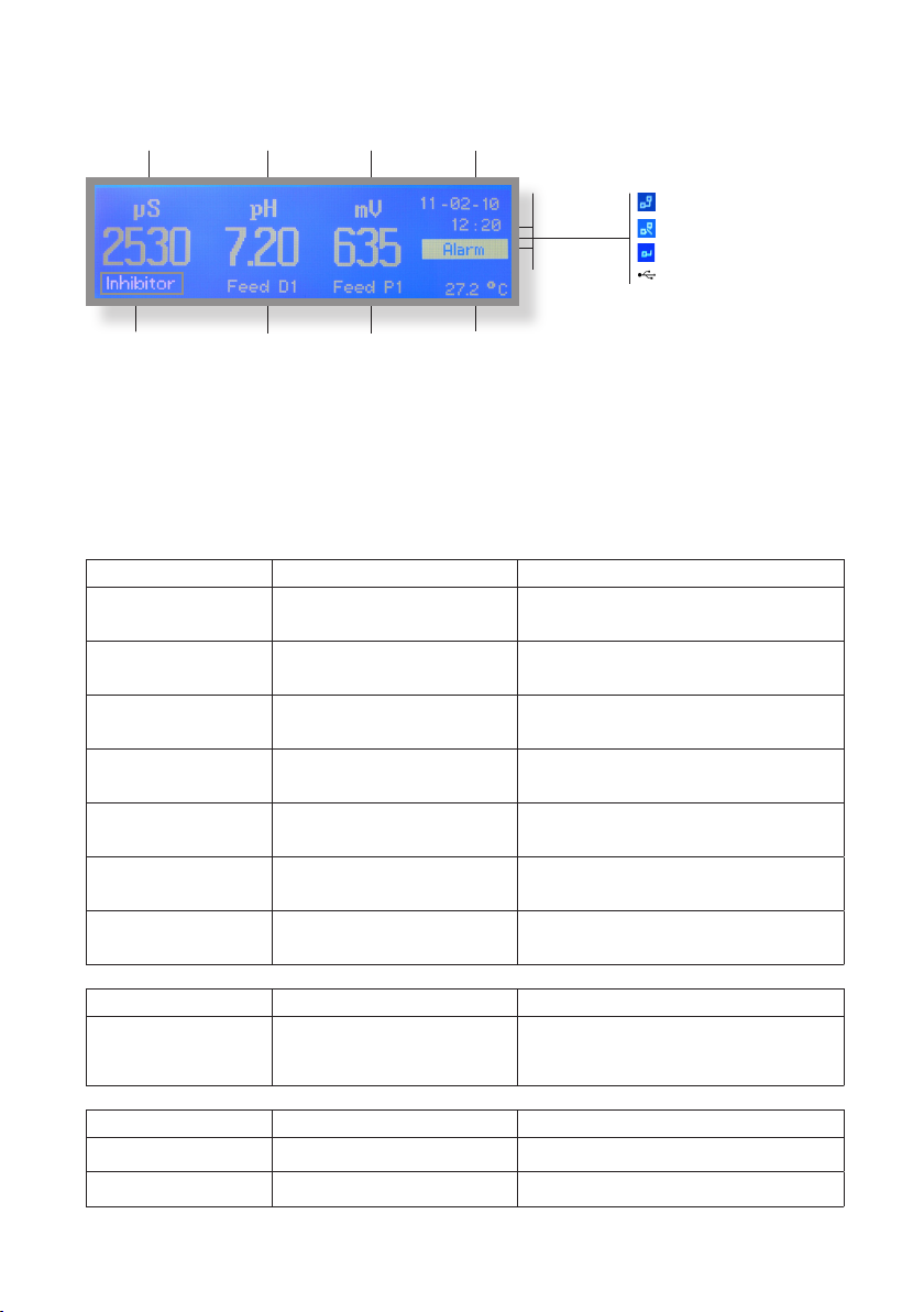
“MTOWER PLUS” main screen.
Conductivity reading pH reading
ORP reading
Local Date
Local Time
LAN Connected - Connected to ERMES
LAN Cable disconnected
LAN Connected - Not connected to ERMES
USB pen-drive connected
Conductivity status
Outputs status
Connection Status
Alarm status
Plant temperature
“MTOWER PLUS” main display shows more information about plant proper functioning. By rotating wheel clockwise the
instrument will show: “Status Output”, “Status Totalizer”, “Status Level”, “Status Alarm”, “Status Biocide”.
See above table for messages explanation.
“MTOWER PLUS” Operating Status Messages.
Conductivity status Message Explanation Action Required
“INHIBITOR”
“BLEED hh:mm”
“PRE BLEED”
“PRE BIOCIDE 1”
“PRE BIOCIDE 2”
“BIOCIDE 2”
“LOCKOUT 1”
“LOCKOUT 2”
INHIBITOR mode in progress.
Ouput 2-E-N active
Corrosion inhibitor dosage in progress.
BLEED hh:mm mode in progress.
Bleed Valve active
Restoring conductivity.
PRE BLEED mode in progress.
Bleed Valve active
Water discharge before dosing biocide.
PRE BIOCIDE 1 or 2 in progress
Output 5-E-N or 6-E-N active
Biocide activator dosage in progress.
BIOCIDE 2 in progress
Output 4-E-N active
Killing dangerous organism in progress.
LOCKOUT 1 or 2 in progress
Bleed Valve disabled
Bleed mode locked after biocide dosage.
No action required.
No action required.
No action required.
No action required.
No action required.
No action required.
“BLEED TIMEOUT” Pre-bleed activity time exceeded Check biocide 1 or 2 menu
Alarm status Message Explanation Action Required
Check alarm by rotating wheel in main screen
Once alarm status is xed the instrument will resume interrputed
until to show “Status Alarm”
“ALARM”
Output 10-11-12 active (see contact mode)
ALARM
Outputs status Message Explanation Action Required
“FEED D1” D1 output active No action required.
“FEED P1” P1 Proportional output active No action required.
9
activities.
Page 10

“MTOWER PLUS” status screen.
From main screen rotate wheel (one click - one menu) clockwise for more information about instrument functioning. For
more information rotate the wheel clockwise. The instrument will show: “Status Output”, “Status Totalizer”, “Status Level”,
“Status Alarm”, “Status Biocide”, SERVICE (for ERMES communication).
Status Output
PreBiocide 1 or 2 : Pre Biocide 1 or 2 status
Biocide 1 or 2 : Biocide 1 or 2 status
PreBleed: Pre Bleed status
Inhibitor: Inhibitor status
Bleed: Output status
Alarm: Output status
Status Totalizer (1unit = 1lt)
Water Meter Input: Main water input totalizer
Water Meter Bleed: Bleed water input totalizer
Water Meter Delta: Plant water totalizer (“delta” between
WMI and WMB)
Status Level
PreBiocide 1 or 2 : Pre Biocide 1 or 2 tank level
Biocide 1 or 2 : Biocide 1 or 2 tank level
Inhibitor: Inhibitor tank level
Redox: product level for ORP (HIGH or LOW)
pH: product level for pH (HIGH or LOW)
10
Status Alarm
High conductivity: HIGH Conductivity Alarm
Low conductivity: LOW Conductivity Alarm
pH High: HIGH pH Alarm
pH Low: LOW pH Alarm
Bleed Timeout: Bleed Timeout Alarm
Flow: No / YES Flow Alarm
mV High: high ORP reading alarm
mV Low: low ORP reading alarm
Off: alarm not active - ON: alarm active
Status Biocide
Week: Week number
Day: dosing day
Next: Next dosing activity
Connection Code for ERMES (through USB cable)
Connection Code for ERMES (through LAN cable)
Page 11
“MTOWER PLUS” basic settings.
Basic settings are: PASSCODEs, Time & Date, International Units.
Standard settings are: Probes calibration and operating modes (bleed - inhibitor - biocide).
Advanced settings are: Flow meter, Alarm and Option menu.
All these three settings must be set in order to properly operate the instrument.
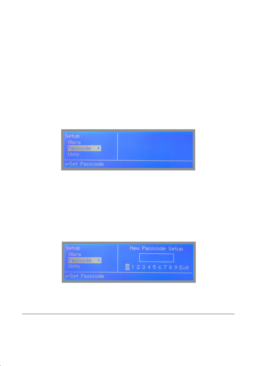
PASSCODE for “Setup” and “Probe” menu access.
To grant access into “Setup” menu press the wheel from main screen, choose “Setup” and enter the PASSCODE.
If this is the rst time here then the PASSCODE is 0000 (factory preset). Press wheel 5 times to grant access.
Otherwise press the wheel 1 time and enter the PASSCODE. Numbers can be selected by rotating the wheel.
To set a new PASSCODE choose “PASSCODE ” from “Setup” menu and enter a four numbers code. Click on “EXIT”
and choose “YES” to save request. The new PASSCODE is now ready.
To change default PASSCODE for “PROBE” menu, repeat procedure once into that submenu.
Note: both the PASSCODEs are independent!
Lost PASSCODE ?
Please dont’ forget the PASSCODE (if changed). In the unfortunate event, please call your local distributor for unlocking procedure. There is no way for you to
recover lost PASSCODE.
11
Page 12
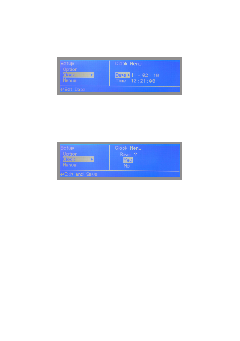
Time & Date setup.
To grant access into “Setup” menu press the wheel from main screen, choose “Setup” and enter the PASSCODE.
Move on “CLOCK” and press the wheel.
To end procedure move cursor on “EXIT” and press wheel to proceed to “Save” request screen. Move wheel on “YES”
to save or “NO” to discard changes.
WARNING: when programming instrument (BIOCIDE) check into STATUS menu that DATE
is correct, otherwise dosing accuracy could be affected. In this case set the correct date
12
and reset instrument (default settings).
Page 13
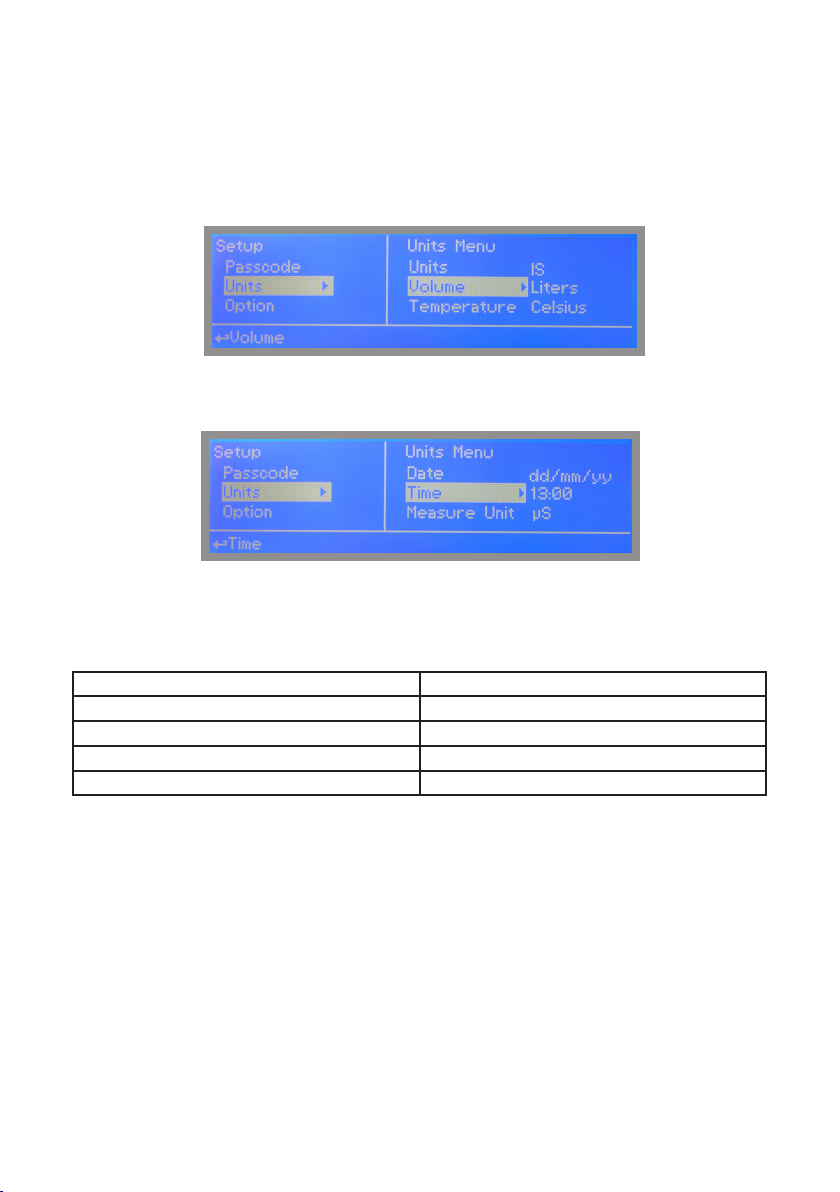
Units setup.
To grant access into “Setup” menu press the wheel from main screen, choose “Setup” and enter the PASSCODE.
Move on “UNITS” and press the wheel.
Once into submenu press wheel twice on “UNITS” and rotate to choose between “US” unit standard or “IS” international
unit standard. See table for differencies.
EUROPE IS (Internationl Standard) USA
Date (DD/MM/YY) Date (MM/DD/YY)
Time 24h Time AM / PM
°C Celsius °F Farhenheit
Liters Gallons
To change conductivity reading scale from uS to PPM move wheel on “MEASURE UNIT” and press it twice.
To end procedure move cursor on “EXIT” and press wheel to proceed to “Save” request screen. Move wheel on “YES”
to save or “NO” to discard changes.
13
Page 14

“MTOWER PLUS” standard settings.
Standard settings are: Probes calibration and operating modes (bleed - inhibitor - biocide).
PASSCODE for “Probe” menu access.
To grant access into “Probe” menu press the wheel from main screen, choose “Setup” and enter the PASSCODE.
If this is the rst time here then the PASSCODE is 0000 (factory preset). Press wheel 5 times to grant access.
Otherwise press the wheel 1 time and enter the PASSCODE. Numbers can be selected by rotating the wheel.
“Calibration uS” menu.
“Calibration uS” menu includes conductivity calibration , temperature compensation and manual or automatic temperature
compensation.Before to begin calibration choose the probe’s scale using FS option (Full Scale)
Conductivity calibration procedure involves a zero calibration (P1) and a 2nd calibration point (P2) that requires a
buffer solution with value near working range. Furthermore TE (Temperature) and CA (Automatica Compensation)
must be set. Note: This procedure assumes that instrument is correctly installed and congured, connected to a
working probe. Calibrate using plant’s temperature otherwise unattended results might occur.
P1 & P2
During this procedure probe must be dry and clean and not installed in plant. Move wheel on “P1” then press wheel,
move cursor on “OK” and press wheel again. Move wheel on “P2” then press wheel to enter into second point calibration
submenu. Prepare buffer solution and dip probe’s sensor on it. Wait until reading value is stable and according to buffer
solution value move wheel until it is the same on display (“uS default” eld). End procedure moving cursor on “OK”.
14
Page 15
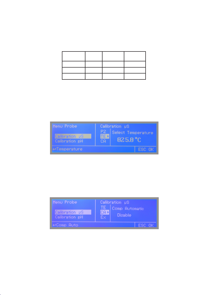
TE & CA
Conductivity measurements are temperature dependent. The degree to which temperature affects conductivity varies
from solution to solution and can be calculated using the following formula: C25 = C / {1+[a/100(t-25)]}
where: C25 = slution conductivity at 25°C, C = conductivity at operating temperature, a = temperature coefcient of
solution %/°C.
Probe read value
(uS or ppm)
5227 1.2 35°C / 95°F 4934
4524 3.5 27°C / 80.6°F 4228
3924 2.1 40°C / 104°F 2984
Alpha (a) Temperature
(°C / °F)
Displayed Value
(us or ppm)
Samples alphas (a) are listed in the table above. To determine that “a” of other solutions, simply measure conductivity at
a range of temperatures and graORP the change in conductivity versus the change in temperature.
“MTOWER PLUS” has either xed or adjustable automatic temperature compensation referenced to a standard
temperature of 25°C. For manual temperature compensation move cursor on “TE”, press wheel and adjust manual
temperature compensation.
Move cursor on “OK” and press wheel again. Move cursor on “CA”, press wheel and choose DISABLE for manual
temperature compensation.
Otherwise for automatic temperature compensation choose “ENABLE” and see “COEFF TEMP” in “OPTIONS” menu
to set % Alpha value.
To end procedure move cursor on “EXIT” and press wheel to proceed to “Save” request screen. Move wheel on “YES”
to save or “NO” to discard changes.
15
Page 16

“Calibration pH” menu.
pH calibration procedure involves two calibration points and it requires two buffer solutions. Default buffer solutions are
pH 4.00 and pH 7.00. pH reading value can be also 30°C temperature compensated from “CA” eld. From “Probe”
menu choose “Calibration pH”.
In the following example instrument will calibrate pH using default buffer solutions values.
Note: this procedure assumes that instrument is correctly congured and a working pH probe connected.
Otherwise unattended results may occurr.
pH7
Calib 1st Point.
Once into “pH Calibration” menu move wheel on “P1” then press wheel to enter into rst point calibration submenu.
Prepare 7.00pH buffer solution and dip probe’s sensor on it. Wait until reading value is stable and according to buffer
solution value move wheel until it is the same on display (“Cal. at” eld). Default value is 7.00pH. To end procedure
move cursor on “OK” and press wheel to proceed to next step.
Note: buffer solution value may change if environment temperature it’s different than 20°C. Read solution’s
label for more information. According to this occurrence “pH Default” must be changed.
16
Page 17

“Calibration pH” menu.
pH4
Calib 2nd Point.
Move wheel on “P2” then press wheel to enter into second point calibration submenu. Prepare 4.00pH buffer solution
and dip probe’s sensor on it. Wait until reading value is stable and according to buffer solution value move wheel until it
is the same on display (“Cal. at” eld). Default value is 4.00pH.
To end procedure rotate cursor on “OK” and move on TE submenu.
Note: buffer solution value may change if environment temperature it’s different than 20°C. Read solution’s
label for more information. According to this occurrence “pH Default” must be changed.
17
Page 18

“Calibration pH” menu.
TE & CA
pH measurements are temperature dependent. The degree to which temperature affects conductivity varies from solution
to solution and can be calculated using the following graphic.
“MTOWER plus” has either xed or adjustable automatic temperature compensation referenced to a standard temperature
of 25°C. For manual temperature compensation move cursor on “TE”, press wheel and adjust manual temperature
compensation.
Move cursor on “OK” and press wheel again. Move cursor on “CA”, press wheel and choose DISABLE for manual
temperature compensation.
Otherwise for automatic temperature compensation choose “ENABLE”
To end procedure move cursor on “EX” and press wheel to proceed to “Save” request screen. Move wheel on “YES” to
save or “NO” to discard changes.
18
Page 19

“Calibration mV” menu.
ORP calibration procedure involves one calibration point and it requires a buffer solution. Default buffer solution should
be near working value. From “Probe” menu choose “Calibration mV”.
In the following example instrument will calibrate ORP using default buffer solutions values.
Note: this procedure assumes that instrument is correctly congured and a working ORP probe connected.
Otherwise unattended results may occurr.
19
Page 20

“Calibration mV” menu.
ORP calibration procedure involves probe’s selection with one point (P1) calibration. From “Menu Calibration” choose
“ORP probe”.
Note: This procedure assumes that instrument is correctly congured and a working ORP probe connected
and installed on system. Measurement must be performed using plant water. Otherwise unattended results
might occurr.
Calibration can be performed in two ways: the rst by alignment with a buffer solution, the second by reading the residual chlorine level of the pool with the DPD1, comparison with the attached graph followed by alignment of the pumps
group. The choice of method is exclusively at the user’s discretion. In both cases, to establish the set-point value, a
check using the DPD1 or other analysis system is necessary. The enclosed graphs provide a reference between the
mV value read by the pumps group and the quantity of residual chlorine expressed in mg/litre, and are linked to the pH
value.
1) Measure buffer solution temperature and verify that it is
the same printed on solution’s label.
2) Remove protective cap from probe and wash probe’s tip
into water. Then dry it by shaking the probe in air.
3) On “MTOWER PLUS” set “Cal. at” value to match buffer
solution value then put probe’s tip into buffer solution and
wait until “MTOWER PLUS” shows a stable reading value
(mV eld).
4)Move cursor on “OK” and press wheel ton corm the new
calibration value. If calibration process fails the instrment
will show “CALIBRATION FAILED”. Repeat procedure
otherwise move on “ESC” and press wheel.
To end procedure move cursor on “OK” and press wheel to proceed to “Save” request screen. Move wheel on “YES” to
save or “NO” to discard changes. If an error occurred during calibration procedure then the instrument will show an error
message and will ask to proceed to a new calibration, cancel current operation or restore default settings.
20
Page 21

“Calibration Temp” menu.
To calibrate probe’s temperature enter into “Calibration Temp” menu. A professioanl thermometer is required to obtain a
reliable calibration. From “Menu Calibration” choose “Calibration Temp”.
Note: This procedure assumes that instrument is correctly installed and congured, connected to a working
probe. Calibrate using plant’s temperature otherwise unattended results might occur.
Using an external thermometer read actual temperature and edit related eld “Calib. at”. Conrm by pressing wheel.
To end procedure move cursor on “EXIT” and press wheel to proceed to “Save” request screen. Move wheel on “YES”
to save or “NO” to discard changes.
21
Page 22

“Inhibitor” menu.
Inhibitor function can operate in 5 feeding modes. Press wheel and rotate to choose most
suitable mode. “WM PPM” submenu can be edited within “L/h” or “cc/st”.
Feed & Bleed.
Once Bleed mode has been set, the operating time for
feeding procedure will be the same as for bleeding.Before
setting this mode rst congure “Bleed Menu” from “Menu
Affected I/O on board: 2-E-N
Setup”.
No further options need to be set.
Feed & % Bleed.
Once Bleed mode has been set, the operating time for
feeding procedure will be a percentage of total time
needed for bleeding.Before setting this mode rst cong-
Affected I/O on board: 2-E-N
ure “Bleed Menu” from “Menu Setup”.
Set percentage time.
Feed & % Time.
The operating time for feeding procedure will be a
percentage (%) of cycle time (Ct).
Affected I/O on board: 2-E-N
E.g.: Ct= 1h 00m and %=50.
Inhibitor activity: 0h 30m.
Choose
Edit
22
Affected I/O on board: 2-E-N and WMI (Makeup)
Affected I/O on board: 2-E-N and WMI (Makeup) and IS
Affected I/O on board: 2-E-N and WMI (Makeup) and IS
Feed & Water Meter (WMI).
The operating time for feeding procedure will be active for
a time (T) every (C) water meter pulses. Before setting
this mode rst congure “Flow meter menu” from “Menu
Setup”.
E.g.: T= 00h 30m and C=0050.
Inhibitor activity: 30min every 50 pulses from water meter (WMI)
Feed & WM Ppm (WMI).
The operating time for feeding procedure will be active to
keep product concentration (Ppm) based on pump’s ow
(L/h liters per hour) and Water Meter counter with a minium
of 10 seconds activity. Furthermore pump’s capacity can
be edited into cc per stroke (cc/st) using ppm to set strokes
needed to dose. Otherwise manual concentration value
(%) can be set (rotate wheel). Before setting this mode
rst connect IS pump to the instrument and congure “Flow
meter menu” from “Menu Setup”.
Page 23

“Biocide 1” and “Biocide 2” menu.
Usually two types of chemicals (e.g.: chlorine based chemical and bromine based chemical) are used to obtain best results
in killing dangerous microorganisms. Use “Biocide 1” and “Biocide 2” menus to congure these tasks. Parameters to set are
the same for both menus.
Note: “Biocide 1” can’t be changed if “Setpoint mV” working mode is set to “Constant Mode” (see page 25).
Parameters to set are:
Pre-bleed (PBLD): Timered or conductivity (uS/PPM) setpoint for bleed valve activity.
Time mode Setpoint mode (conductivity probe reading)
Choose
Bleed valve is open for set time
Bleed valve is open if probe’s conductivity
read value exceeds set value
Pre-biocide (PBIO): This option set Pre-biocide (1 or 2) output active for set time.
Pre-biocide is generally used for biocide-activator chemicals.
Pre-biocide 1 will activate 5-E-N output. Pre-biocide 2 will activate 6-E-N output.
Lockout (LCK): This option lock (keep closed) bleed valve for
set time at the end of biocide activity.
Week (WK): This option set events repetitivity on daily basis
for set amount of time.
E.g.: 00 01 @ 01:00
hh mm hh mm
Biocide activity will start every
Tuesday for 1 minute at 01:00 AM*
NOTES: 1) Activity execution order for selected options is: 1st Pre-bleed
2nd Pre-biocide
3rd Biocide
4th Lockout
2) Pre-bleed option in conductivity mode has a time limit that can be set from “BLEED” menu. If conductivity value can’t be
restored within a time then the bleed valve will be closed and an alarm generated (“Bleed Timeout”).
3) Set 00h 00m to disable single option
4) *Execution time, for selected options, will begin calculating total events time and it will begin prior biocide time activity.
(see “WK” option for starting time).
23
Page 24

“Bleed” menu.
A method for controlling the amount and concentration of make-up water and chemicals introduced into the recirculating
water of a cooling tower system. A oat operated make-up valve controls the addition of make-up water to the tower. As
make-up water is added to the tower a vacuum is produced at an injector valve which draws chemicals from a chemical
holding tank into the make-up water, thereby allowing precise control of the chemical concentration in the make-up liquid.
Further, a bleed valve is provided which is responsive to the vacuum produced at the injector valve and bleeds a portion
of the recirculating water to waste. From “Menu Setup” choose “Bleed” and congure the following parameters:
Setpoint: target value for conductivity.
Dead Band: “MTOWER PLUS” opens bleed valve when reaching setpoint and it leaves valve opens until conductivity value
reaches dead band set value. Choose “-“ before Dead Band value to invert bleed valve working mode.
E.g.: Setpoint is 4000 uS and Dead Band is 500 uS
Neutral Zone
Bleed Valve Closed
Bleed ValveOpen
3500 4000
Time Limit: this option set a time limit within restoring conductivity value. Outreaching this time the “MTOWER PLUS” will
close bleed valve and generate an alarm.
Manual Bleed: this option manually operates bleed valve for set time. Valve operation begins immediately after wheel is
pressed to conrm working time.
To end procedure move cursor on “EXIT” and press wheel to proceed to “Save” request screen. Move wheel on “YES”
to save or “NO” to discard changes.
24
Page 25

“Set-Point ORP menu” working modes
For “Digital D1” output, setpoint can be set between On/Off mode, PWM mode or disabled (OFF).
For “Proportional P1” output (blocks 7 and 8), setpoint can be set using Proportional mode or disabled (OFF).
Both options can be operate as “Timer Biocide 1” (mV channel operates within Biocide 1 set time) or “Constant” (three
cannels are all independent). Move wheel on “Working mode” to change it.
“Set-Point ORP” (on/off) mode - Digital D1
This mode is valid for “Digital D1” output. On/Off mode set the instrument to operate using two set values that enable
or disable the ORP pump. To use this mode move cursor on “Working Mode”. Press the wheel and select it.
ON/OFF mode
Set ORP value at 680mV ON and 700mV OFF. The difference between the two ORP values is called HYSTERESIS.
Instrument will enable the ORP pump when reading value will decrease at 680mV
At 680mV the ORP pump will be enabled until reading value will increase at 700mV.
Pulse Speed: pulses per minute setting.
ON
OFF
680 700
25
Page 26

“Set-Point ORP” (PWM) mode - Digital D1
This mode is valid for “Digital D1” output.
Pulse-width modulation (PWM) of a signal or power source involves the modulation of its duty cycle, to either convey
information over a communications channel or control the amount of power sent to a load.
This mode works over a settable (0 to 100 seconds) time to switch on or off selected output.
Time resolution is 5 seconds, 5 steps. During this time if reading value will move towards a set value (on or off) the PWM
will operate the output on timered basis. Reaching the set value the PWM will permanently leave on or off the output.
Parameters to set are:
Unit Value + %: (time activity towards set value. 0% means 0 seconds. 100% means 100 seconds.)
mV range: two pH value between PWM operates.
E.g: set rst value at 700 = 00% and second value at 680=60%.
For reading values ≥ 700 output will always be OFF.
For reading values ≤ 680 output will be ON for 60 seconds and OFF for 40 seconds.
If reading value is 690 mV the ouput will be ON with a 30% of total set time. (ON for 30 seconds, OFF for 70 seconds).
26
Page 27

“Set-Point ORP” - Proportional P1
This mode is valid for “Proportional P1” output (blocks 7 and 8).
Proportional mode set the instrument to operate using a calculated percentage between two set values that enable
or disable the ORP pump. To use this mode move cursor on “Proportional P1”. Press the wheel and select it.
PROPORTIONAL MODE between 700(0 P/m) and 680 (180 P/m). [P/m: pulses per minute]
This mode operates ORP pump for a value lower that 680mV with maximum dosing capacity (180strokes) and it will
stop ORP pump for a reading value higher than 700 mV.
A 690 mV reading value will operate ORP pump with a 90 strokes capacity calculated on strokes settings.The pump
will stay on with 90 strokes dosing capacity. To end procedure move cursor on “OK” and press wheel. Choose “SAVE”
to save setup or “NO” to discard changes.
27
Page 28

“Set-Point pH menu” working modes
For “Digital D1” output, setpoint can be set between On/Off mode, PWM mode or disabled (OFF).
For “Proportional P1” output (blocks 9 and 10), setpoint can be set using Proportional mode or disabled (OFF).
“Set-Point pH” (on/off) mode ALKALI
This mode is valid for “Digital D1” output. On/Off mode set the instrument to operate using two set values that
enable or disable the pH pump. To use this mode move cursor on “Working Mode”. Press the wheel and select it.
ON/OFF mode while dosing ALKALI
Set pH value at 7.00 OFF and 6.90 ON. Set Pulse Speed per minute (strokes per minute) based on dosing device capabilities.
Instrument will leave the pH pump active until reading value will increase up to 7.00pH.
At 7.00pH the pH pump will be disabled until reading value will decrease under 6.90pH.
ON
OFF
6.90 7.00
28
Page 29

“Set-Point pH” (on/off) mode ACID
This mode is valid for “Digital D1” output. ON/OFF mode while dosing ACID
Set pH value at 7.00 OFF and 7.10 ON. Set Pulse Speed per minute (strokes per minute) based on dosing device capabilities.
Instrument will leave the pH pump active until reading value will decrease up to 7.00pH
At 7.00pH the pH pump will be disabled until reading value will increase up to 7.10pH.
ON
OFF
7.00 7.10
To end procedure move cursor on “OK” and press wheel to proceed to “Save” request screen. Move wheel on “YES” to
save or “NO” to discard changes.
Did you know ?
In chemistry, an alkali is a basic, ionic salt of an alkali metal or alkaline earth metal element. Alkalis are best known for
being bases (compounds with pH greater than 7) that dissolve in water. The adjective alkaline is commonly used in English
as a synonym for base, especially for soluble bases. This broad use of the term is likely to have come about because
alkalis were the rst bases known to obey the Arrhenius denition of a base and are still among the more common bases.
Since Brønsted-Lowry acid-base theory, the term alkali in chemistry is normally restricted to those salts containing alkali
and alkaline earth metal elements.
An acid (often represented by the generic formula HA [H+A−]) is traditionally considered any chemical compound that,
when dissolved in water, gives a solution with a hydrogen ion activity greater than in pure water, i.e. a pH less than 7.0.
That approximates the modern denition of Johannes Nicolaus Brønsted and Martin Lowry, who independently dened an
acid as a compound which donates a hydrogen ion (H+) to another compound (called a base). Common examples include
acetic acid (in vinegar) and sulfuric acid (used in car batteries). Acid/base systems are different from redox reactions in
that there is no change in oxidation state.
29
Page 30

“Set-Point pH” (PWM)
This mode is valid for “Digital D1” output. Pulse-width modulation (PWM) of a signal or power source involves the
modulation of its duty cycle, to either convey information over a communications channel or control the amount of power
sent to a load.
This mode works over a settable (0 to 100 seconds) time to switch on or off selected output.
During this time if reading value will move towards a set value (on or off) the PWM will operate the output on timered
basis. Reaching the set value the PWM will permanently leave on or off the output.
Parameters to set for this mode are:
Unit Value + %: (time activity towards set value. 0% means 0 seconds. 100% means 100 seconds.)
pH range: two pH values within PWM operates.
For example: set rst pH value at 8.00 = 100% and second pH value at 4.0 = 0%.
For reading values ≥ to 8.00 the output will be permanently ON.
For reading values ≤ 4.0 the output will be permanently OFF.
For reading value of 7.00 the output will be OFF for 25 seconds, ON for 75 seconds.
For reading value of 6.00 the output will be OFF for 50 seconds, ON for 50 seconds.
30
0% 50% 75% 100%
ON
OFF
4.00 5.00 6.00 7.00 8.00
Page 31

“Set-Point pH” (Proportional)
This mode is valid for “Proportional P1” output (blocks 9 and 10).
Proportional mode set the instrument to operate using a calculated percentage between two set values that enable
or disable the pH pump. To use this mode move cursor on “Proportional P1”. Press the wheel and select it.
PROPORTIONAL mode between 7pH(0 P/m) and 8pH (180 P/m). p/m is : pulses per minute
In this mode the pH pump will be “ON” for values greater than 8pH with maximum set pulses per minute capacity (e.g.:
180) and it’ll be “OFF” for values lower than 7pH. For values of 7.5pH pump will be “ON” with 90 pulses per minute
capacity. To end procedure move cursor on “OK” and press wheel to proceed to “Save” request screen. Move wheel on
“YES” to save or “NO” to discard changes.
31
Page 32

“MTOWER PLUS” advanced settings.
Advanced settings are: Flow meter, Alarm and Option menu.
“Flow meter” menu.
This menu allows to congure: totalizer for water meter input , totalizer for water meter bleed, working mode and counters
reset.
WMI: Main water input totalizer (not editable)
WMB: Bleed water input totalizer (not editable)
FM Unit: L/P (liters per pulses) or P/L (pulses per liters)
RST TOT : reset both WMI and WMB counters
To end procedure move cursor on “EXIT” and press wheel to proceed to “Save” request screen. Move wheel on “YES”
to save or “NO” to discard changes.
32
Page 33

“Alarm” menu.
This menu allows to enable / disable / set all system alarms and related outputs.
LOC: “LOW CONDUCTIVITY” alarm.
LPH: “LOW pH” alarm.
LMV: “LOW ORP” alarm.
OFF: alarm disabled
ABS: (absolute) alarm on set value*
TRK: (track) alarm on bleed setpoint minus track value*
Track alarm (TRK) e.g.:
Bleed setpoint is set to 4000 and track alarm is set to 1000.
Alarm will switch on at 3000.
HIC: “HIGH CONDUCTIVITY” alarm.
HPH: “HIGH pH” alarm.
Choose
Edit
HMV: “HIGH ORP” alarm.
OFF: alarm disabled
ABS: (absolute) alarm on set value*
TRK: (track) alarm on bleed setpoint minus track value*
Track alarm (TRK) e.g.:
Bleed setpoint is set to 4000 and track alarm is set to 1000.
Alarm will switch on at 5000 (4000+1000).
CLS: Chemicals level alarm.
STOP: low chemical tank level alarm is generated and related output disabled
NO: option disabled
NFW: ow sensor alarm
STOP: no ow alarm generated*
NO: option disabled
OUT AL: Alarm contact activation
EN: Alarm contact enabled
DIS: Alarm contact disabled
*Alarm contact (10-11-12) enabled, all outputs disabled.
To end procedure move cursor on “EXIT” and press wheel to proceed to “Save” request screen. Move wheel on “YES”
to save or “NO” to discard changes.
33
Page 34

“Options” menu.
Press wheel and rotate to choose.
TAU: if probes reading values are displayed too fast
increase TAU value to stabilize them. Default value is 03.
Maximum value is 30.
Coeff Temp: Temperature compensation. Minimum value
is 0% (disabled), maximum value is 5%. See page 15 for
more info.
Startup Delay: Startup time delay at instrument startup
(power on). Minimum value is 0m (disabled), maximum
value is 99minutes.
FLOW: Flow contact (34-35-36) working mode.
Set to “NORMAL” for Normally Open (N.O.) contact type.
Set to “REVERSE” for Normally closed (N.C.) contact type.
Set to “DISABLED” to disable contact.
OUT CURRENT: mA current output conguration.
Set to 4/20 mA for 4 (setpoint low) and 20 (setpoint high) mode.
Set to 0/20 mA for 0 (setpoint low) and 20 (setpoint high) mode.
Cd mA High and Cd mA Low are related
to maximum and minimum conductivity value
for “mA output 1”.
Temp mA HI and Temp mA LO are related
to maximum and minimum temperature value
for “mA output 2”.
34
pH mA High and ORP mA Low are related
to maximum and minimum pH value
for “mA output 3”.
mV mA High and ORP mA Low are related
to maximum and minimum ORP value
for “mA output 4”.
NUMBER WEEK: Set weeks number for “Biocide 1” and
“Biocide 2” working mode. See page 18 for more info.
FACT. DEFAULT: it reverts instrument to factory settings
including PASSCODE (“0000”).
IF ALARM: set this option to DISABLE if mA outputs must
be disabled during an alarm event or ENABLE to let mA
outputs enabled during an alarm event.
Page 35

“Manual” menu.
This menu allows to manually operate all outputs. Move wheel on related output, press wheel two times to enable (ON)
and press wheel one more time to disable (OFF) selected output. Press one time again to re-enable (ON) output and
so on.
Outputs available are:
This option manually operate output on 1-E-N blocks.
This option manually operate output on 9 - 10 blocks (I/O connections)
This option manually operate output on 7 - 8 blocks (I/O connections)
This option manually operate output on 11 - 12 blocks (I/O connections)
This option manually operate “Bleed” output on 7-8-9 blocks.
This option manually operate “inhibitor” output on 2-E-N blocks.
This option manually operate “pre-biocide 1” output on 5-E-N blocks.
This option manually operate “pre-biocide 2” output on 6-E-N blocks.
This option manually operate output on 3-E-N blocks.
This option manually operate “biocide 2” output on 4-E-N blocks.
This option manually operate “general alarm output” output on 10-11-12 blocks.
OUT D1 pH
OUT Prop pH
OUT Prop mV
OUT Inhibitor
OUT Bleed
OUT INHIB
OUT PRE-BIO 1
OUT PRE-BIO 2
OUT D1 mV
OUT BIO 2
OUT ALARM
This option manually operate “mA output 1” output on 13-14 blocks.
This option manually operate “mA output 2” output on 13-15 blocks.
This option manually operate “mA output 3” output on 13-16 blocks.
This option manually operate “mA output 4” output on 13-17 blocks.
Move wheel on “EXIT” to return to “Menu setup” and automatically revert outputs to their original status.
35
OUT mA 1
OUT mA 2
OUT mA 3
OUT mA 4
Page 36

Appendix A - Conductivity Probe Module.
Located in upperside of mainboard there are four connectors that can be used to install probe modules. Modules come
pre-installed upon request. Identify installed modules to correctly connect probes.
Connect probe as follows:
Block n.1 :Shield
Block n.2 : Black (probe)
Block n.3 : Red (probe)
For versions PT / NTC connect
ECDS IND PT PROBE
Connect 4 probe wires to MDIND module as follow:
Block n.1 : blue
Block n.2 : green
Block n.3 : red
the remaining wires on the
main board temperature input
1 2 3
MDCD
1 2 3
MDECDSIND
Connect 4 PT100 wires to mainboard (ref. p. 5)
as follow:
Block n. 50 + 51: white
Block n. 52 + 53 : black
INDUCTIVE CONDUCTIVITY module (ECDIND probe)
8 WIRES CABLE:
4 PROBE WIRES
4 PT100 WIRES
36
1 2 3 4
MDIND
Connect 4 probe wires to MDIND module as follows:
Block n.1 : blue
Block n.2 : black
Block n.3 : grey
Block n.4 : red
Connect 4 PT100 wires to mainboard (ref. p. 5) as follows:
Block n. 50 : green
Block n. 51 : orange
Block n. 52 : white
Block n. 53 : yellow
Page 37

Appendix B - Dimensions
ENCLOSURE
IP65 enclosure (NEMA4x)
MTOWER control instruments are manufactured in ABS housing to ensure
protection against aggressive chemicals and tough environment.
37
ENVIRONMENT
-10°C ÷ 50°C (14°F ÷ 122°F)
0÷95% (non condensing) relative humidity
Page 38

Appendix C - Communication “RS485” menu.
Prior to install the instrument into an RS485 local system a unique ID NUMBER (from 1 to 30) and ID NAME (station
name) must be set. Rotate wheel and edit elds. If ID number has already assigned an error message will follow after ID
Check (move cursor on CHECK and press wheel). In this event try using another number.
“GSM” menu.
Instrument may remotely send SMS alarm messages using its own modem (sold as option). It can be congured as
follows:
SMS1 / SMS2 /SMS3.
Using the wheel enter a mobile phone that will receive alert SMS messages if something wrong occurrs. SMS number
must be set using local number format. For example : 3391349134 will send an SMS message to mobile phone.
Log level (and SMS frequency alert) may be set using options in “ACTIVE MSG” within “GSM menu”.
(this menu may looks differently, ex.:)
MSG Flow (Flow)
MSG Bio 1 e 2 (Biocide)
MSG PreBio 1 e 2 (Pre-biocide)
MSG Inhib (Inhibitor)
MSG HI uS
MSG Lo uS
MSG Bld T (Bleed)
- TO AVOID UNDESIRED MESSAGES USE CAREFULLY LOG SETUP -
- WARNING: THIS FUNCTION COULD NOT BE FREE OF CHARGE. DEPENDING ON YOUR OPERATOR CONTRACT IT
COULD GENERATE PAYING SMS TRAFFIC !
“Service”
This “view only” menu shows probes reading live and instrument ID for ERMES connection (if device’s connected).
Press “ESC” to exit.
Connection Code for ERMES (through USB cable)
Connection Code for ERMES (through LAN cable)
38
Page 39

“TCP/IP” menu.
The instrument can be remotely operated using a standard ethernet connection (sold as option). A static or dynamic IP
address and a CAT5 ethernet cable is required. According to your network capacity connection speed is 10/100Mbps.
To obtain a valid IP address and subnet mask contact your net administrator. Enter parameters and move cursor on
“SAVE” to store parameters then move on “OK” and press wheel to save and activate conguration.
Based on your network conguration choose to obtain network parameters automatically (DYNAMIC) or manually
(STATIC).
See “ERMES Communication Software” manual for proper PC software conguration.
What is a static IP address/dynamic IP address?
A static IP address is a number (in the form of a dotted quad) that is assigned to a computer by an Internet service provider (ISP)
to be its permanent address on the Internet. Computers use IP addresses to locate and talk to each other on the Internet, much the
same way people use phone numbers to locate and talk to one another on the telephone. When you want to visit whatis.com, your
computer asks a domain name system (DNS) server (think telephone information operator) for the correct dotted quad number
(think phone number) for whatis.com and your computer uses the answer it receives to connect to the whatis.com server.
It would be simple if every computer that connects to the Internet could have its own static IP number, but when the Internet was
rst conceived, the architects didn’t foresee the need for an unlimited number of IP addresses. Consequently, there are not enough
IP numbers to go around. To get around that problem, many Internet service providers limit the number of static IP addresses
they allocate, and economize on the remaining number of IP addresses they possess by temporarily assigning an IP address to
a requesting Dynamic Host Conguration Protocol (DHCP) computer from a pool of IP addresses. The temporary IP address is
called a dynamic IP address.
Requesting DHCP computers receive a dynamic IP address (think temporary phone number) for the duration of that Internet ses-
sion or for some other specied amount of time. Once the user disconnects from the Internet, their dynamic IP address goes back
into the IP address pool so it can be assigned to another user. Even if the user reconnects immediately, odds are they will not be
assigned the same IP address from the pool. To keep our telephone telephone analogy going, using a dynamic IP address is similar to using a pay phone. Unless there is a reason to receive a call, the user does not care what number he or she is calling from.
There are times, however, when users who connect to the Internet using dynamic IP wish to allow other computers to locate them.
Perhaps they want to use CU-SeeMe or use a VoIP application to make long distance phone calls using their IP connection. In that
case, they would need a static IP address. The user has two choices; they can contact their ISP and request a static IP address, or
they can use a dynamic DNS service. Either choice will probably involve an additional monthly fee.
Using a dynamic DNS service works as if there was an old-fashioned telephone message service at your computer’s disposal.
When a user registers with a DNS service and connects to the Internet with a dynamic IP address, the user’s computer contacts
the DNS service and lets them know what IP address it has been assigned from the pool; the service works with the DNS server
to forward the correct address to the requesting DHCP computer. (Think of calling the message service and saying “Hi. I can be
reached at 435.44.32.111 right now. Please tell anyone who tries to reach me to call that number.) Using a dynamic DNS service to
arrange for computers to nd you even though you are using a dynamic IP address is the next-best thing to having a static IP.
39
Page 40

“GPRS” menu.
Instrument can be remotely operated using an embedded standard GPRS modem (sold as option). In order to activate
this service please ensure that the following steps are correctly completed:
- Make certain the antenna location is not shielded by metal objects or near sources of electrical ‘noise’.
- Make certain the distance from the antenna to the “MTOWER” unit is within cable length.
- Do not route the cable where it could be pinched in doors, windows etc.
- Ensure that SIM into “MTOWER” modem is correctly inserted, activated and within operator range.
See “ERMES Communication Software” manual for proper PC software conguration.
Instrument can be set for automatic conguration (Conguration option set to “Automatic”) or manually (Conguration
option set to “Manual”) based on your SIM data access parameters. For manual conguration option enter APN (access
point name) and SIM phone number. Move wheel on “OK” to save and move on “ESC” to go back to main menu.
WARNING: THIS FUNCTION COULD NOT BE FREE OF CHARGE. DEPENDING ON YOUR OPERATOR CONTRACT IT
COULD GENERATE PAYING DATA TRAFFIC !
“Email” menu.
If Ethernet module or GPRS module is installed (sold as option) the instrument can be congured to send email alarm
messages up to two recipients. Click on “Email 1” or “Email 2” and enter email address.
“LOG” menu.
This function records instrument acitvity (date, hour, temperature, uS, totalizer I/O, alarms, outputs). It starts for
selected frequency period (every) at requested time (time). SET DATE & TIME BEFORE TO ENABLE LOG. IF NOT
POWERED FOR ABOUT 30 DAYS THE INSTRUMENT WILL LOOSE DATE/TIME
Set ACTIVE to “enabled” to activate log recording.
TIME: recording start time (time format 23h e 59min)
EVERY: recording frequency (time format 23h e 59min)
Note: advanced log control (graph, printing, comparison tables, event ltering, etc) is available through “ERMES
Communication Software” for PC.
See “ERMES Communication Software” manual for proper PC software conguration.
Access point name (APN) identies an IP packet data network (PDN), that a mobile data user wants to communicate with. In addition to identifying a PDN, an
APN may also be used to dene the type of service, (eg connection to wireless application protocol (WAP) server, multimedia messaging service (MMS)), that
is provided by the PDN. APN is used in 3GPP data access networks, eg general packet radio service (GPRS), evolved packet core (EPC).
40
Page 41

“LOG USB” Module
Located under mainboard cover there is a four pins connector that can be used to install “USB data log module”
or “SMS module”. Modules come pre-installed upon request and may appear different as shown (different
configurations).
“USB data log module” records instrument activities. These information can be permanently stored into a standard
USB pendrive. Pendrive can be connected to a PC using “ERMES” web www.ermes-server.com to review and print
instrument’s activities. To obtain reliable results with this feature please set instrument ID and NAME from
“RS485 Setup” menu and activate log recording from “LOG SETUP” menu.
Activity LED
Power LED
Standard USB pendrive
(not included)
Insert USB pendrive here
(right side of instrument)
After usage put back USB cap
HOW TO RECORD INSTRUMENT’S ACTIVITIES INTO USB PENDRIVE ?
Insert USB pendrive into USB connector (located on the right side of instrument). Instrument will save data log on
USB pendrive.
HOW TO REVIEW INSTRUMENT’S ACTIVITIES RECORDED INTO USB PENDRIVE ?
It’s necessary to connect to web “ERMES” www.ermes-server.com to review USB pendrive info on a PC.
41
Page 42

Appendix D - MODBUS Setup
Modbus is a serial communications protocol originally published by Modicon (now Schneider Electric) in 1979 for
use with its programmable logic controllers (PLCs). Simple and robust, it has since become a de facto standard
communication protocol, and it is now a commonly available means of connecting industrial electronic devices.
From main menu select SETUP then MODBUS to access the options. Set the communication speed according to the
PLC system available. Set the ID assigning an UNIQUE address to avoid conflicts.
42
1 2 3
1: GND
2: A-RS485 (+)
3: B-RS485 (-)
Page 43

Appendix C - Motorized valve connection
43
Page 44

Addendum “Water Meter” on mA module
Enter into “Water Meter” menu to setup Flow Meter configuration type, see total amount of liters passed through
water meter, reset totalizer and setup a timeout alarm for no water flow. The alarm will be notified into main screen
and water meter status (see page 6).
Tot WMI: water passed through water meter
FM Input: Water Meter Working Mode
RST TOT: reset totalizer
Timeout: countdown to “no water flow alarm”
FM Input can be set to operate Water Meter as 0-20mA or 4-20mA input, P/L (pulses per liter) or L/P (liters per pulse).
Connect as follows if mA working mode is enabled:
Block 1 : red wire (+)
Block 2 : black wire (-)
1 2
44
Page 45

Appendix - WIFI Connection
Within Communication Menu choose “WIFI” to bring wireless sub-menu. Wait until desired wireless network appears,
move wheel on it then click. Enter WEP / WPA / WPA2 password (if required) and wait until connection has been
estabilished and WiFi signal strength appears. To obtain a reliable connection be sure to install the controller within
WiFi range. See your router features and installation procedure for best results.
WiFi signal strength
45
Page 46

46
Page 47

INDEX.
INTRODUCTION page 3
The wheel page 3
MAINBOARD CONNECTIONS page 4
COOLING TOWER BASICS KNOWLEDGE page 6
“MTOWER PLUS” BASIC TREATMENTS page 8
“MTOWER PLUS” main screen page 9
“MTOWER PLUS” operating status messages page 9
“MTOWER PLUS” status screen page 10
“MTOWER PLUS” BASIC SETTINGS page 11
PASSCODE setup page 11
Time & Date setup page 12
Unit setup page 13
“MTOWER PLUS” STANDARD SETTINGS page 14
PASSCODE setup page 14
“Calibration uS” menu page 14
“P1” & “P2” page 14
“TE” & “CA” page 15
“Calibration pH” menu page 16
“Calibration mV” menu page 19
“Calibration Temp” menu page 21
“Inhibitor” menu page 22
“Biocide 1” and “Biocide 2” menu page 23
“Bleed” menu page 24
“Set-Point mV” menu modes page 25
“Set-Point mV” on/off mode (D1) page 25
“Set-Point mV” PWM mode (D1) page 27
“Set-Point mV” proportional mode (P1) page 27
“Set-Point pH” menu modes page 28
“Set-Point pH” on/off mode (D1) page 29
“Set-Point pH” PWM mode (D1) page 30
“Set-Point pH” proportional mode (P1) page 31
47
“MTOWER PLUS” ADVANCED SETTINGS page 32
“Flow meter” menu page 32
“Alarm” menu page 33
“Options” menu page 34
“Manual” menu page 35
APPENDIX - CONDUCTIVITY PROBE page 36
APPENDIX - DIMENSIONS page 37
APPENDIX - COMMUNICATION / SERVICE page 38
APPENDIX - MODBUS page 42
APPENDIX - Motorized EV5 page 43
APPENDIX - Water Meter on mA Module page 44
APPENDIX - WIFI Connection page 45
Page 48

When dismantling this instrum ent please separate material types and send them according to local recycling disposal requirements.
We appreciate your efforts in supporting your local Recycle Environmental Program.
Working together we’ll form an active union to assure the world’s invaluable resources are conserved.
48
 Loading...