

Page 1
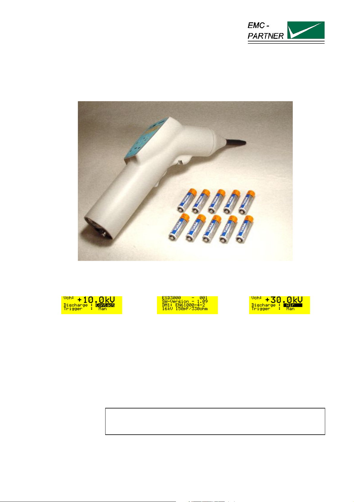
User Manual ESD3000
Title: EMC Test System ESD3000
Date: 22.03.2002
Division Manager: M. Lutz
Quality Manager: R. Henz
Revised: 10.May 2016
EMC TESTER
Electrostatic Discharge ESD3000
E-ESD3000-E-Manual.doc 1/66
Page 2
ESD3000-System
ATTENTION
This user manual provides information necessary for operation of the test
equipment.
Throughout the users manual, standard references are used as an aid to
understanding only.
The relevant standard(s) must be obtained and used in conjunction with this
users manual
Declaration of Conformity
See sheets attached at the end of this user manual:
• Declaration of conformity to product standards
• Declaration of conformity to low voltage directive
• Declaration of conformity to EMC directive
2/66
Page 3

ESD3000-System
Contents:
1 DESCRIPTION 7
1.1.1 Electrostatic discharge ESD 7
1.1.2 How ESD, EFT, SURGE, DIPS differ 7
1.2 Technical data of the ESD3000 and DM Discharge Modules 8
1.2.1 ESD3000 equipment 8
1.2.2 Discharge Module ESD3000DM1 (IEC 61000-4-2 and EN61000-4-2) 8
1.2.3 Discharge Module ESD3000DM2 (ISO TR10605 - inside vehicle, module tests) 9
1.2.4 Discharge Module ESD3000DM4 (MIL-STD-883E, MIL-STD-464, GR78-CORE) 9
1.2.5 Discharge Module ESD3000DM5 (RTCA/DO 160) 9
1.2.6 Discharge Module ESD3000DM6 (IEC 61340-3-1, JEDEC 22-A114, MIL-STD-750D9) 10
1.2.7 Discharge Module ESD3000DM7 (IEC 61340-3-2, JEDEC 22-A115) 10
1.2.8 Discharge Module ESD3000DM8 (IEC 60571, EN 50155) 10
1.3 Technical data of the ESD3000RM and DN Discharge Networks 11
1.3.1 Discharge Network ESD3000DN2 (ISO TR10605 - inside vehicle, module tests) 11
1.3.2 Discharge network ESD3000DN3 (ISO TR10605 -outside vehicle, sensitive classification) 11
1.3.3 Discharge Module ESD3000DN4 (MIL-STD-883E, MIL-STD-464, GR78-CORE) 12
1.3.4 Discharge Module ESD3000DN5 (MIL-DLT-23659D, STANAG 4239, MIL-STD 331) 12
1.3.5 Discharge Module ESD3000DN6 (MIL-DLT-23659D, STANAG 4239, MIL-STD 331) 12
1.4 Mechanical dimensions 13
1.5 Power Consumption 13
1.6 Accessories, dimensions 14
1.6.1 Included articles, dimensions 14
1.6.2 Standard accessories 14
2 SAFETY 15
2.1 Safety standard 15
2.2 Climatic Conditions 15
2.3 Precautionary measure during use 16
2.4 Electromagnetic Compatibility 16
2.5 The manual is an integral part of the equipment. Refer to the manual. 16
2.6 No operation of ESD3000 without ground wire 16
3 MECHANICAL STRUCTURE 17
3.1 General 17
3.2 Overview on ESD3000 system 17
3.2.1 ESD3000 Contact Discharge (CD) up to max. 10kV with Discharge Module (DM ) 17
3.2.2 ESD3000 Contact Discharge (CD) up to max. 30kV with (RM and (DM ) 17
3/66
Page 4

ESD3000-System
3.2.3 Avoiding Mechanical Damage to Discharge Modules 18
4 CONTROL PANEL 19
4.1 Front panel of the ESD3000 19
4.2 Interchange of discharge modules 20
4.3 Interchange of the finger and tips 20
4.4 Inputs and Outputs 20
5 PREPARATION FOR OPERATION 21
5.1 Attention, Refer to Manual 21
5.1.1 ESD test set up 21
5.1.2 Test set-up for table top equipment 22
5.2 Practical testing sequence 23
6 TESTING WITH THE ESD3000 25
6.1 Contact discharge 25
6.2 Air discharge 26
6.3 Main parameter setting with the buttons on the front plate 27
6.4 The different software menus of the ESD3000 29
6.4.1 Repetition, number of pulses, count mode 29
6.4.2 Menu „Ramps“ 30
6.4.3 Menu „Setup“ 31
6.4.4 Menu „Settings“ 32
6.4.5 Menu „Service“ 32
6.4.6 Reset of the ESD3000 to default values 33
6.5 Parameter changing during operation „RUN Mode“ 33
7 MAINTENANCE AND SERVICING 35
7.1 Maintenance 35
7.2 Verification of the ESD3000 by the user 35
7.3 Verification of the ESD3000 by EMC PARTNER AG 35
7.4 System Reset 36
7.5 Caution with calibration labels 36
7.6 What must be done when the serial number is not indicated during the start up 36
4/66
Page 5

ESD3000-System
8 WHAT MUST BE DONE FOLLOWING FAILED OPERATION 37
8.1 Display messages 37
8.1.1 Examples of messages 37
8.2 Service; Repairs 37
8.3 Spare parts list 37
8.4 Service department of EMC PARTNER AG 38
9 CHARGING THE BATTERIES OR REPLACING BATTERIES 39
10 PACKAGING AND TRANSPORT 41
10.1 Packaging 41
10.2 Transport 41
11 RECYCLING / DISPOSAL 43
11.1 RoHS directive 2002/95/EG 43
11.2 WEEE directive 2002/96/EG 43
11.3 Information for dismantling 43
11.4 Parts which can be recycled 43
11.5 Parts which can not be recycled 43
12 MODULES AND ACCESSORIES 45
12.1 ESD3000 with DM discharge modules 45
12.2 Pictures of the accessories 48
13 E3LOADER AND SERIAL COMMUNICATION 51
13.1 Remote control with „E3Loader“ 51
13.2 Controlling ESD3000 51
13.3 Module Calibration 52
13.4 Firmware Upload 52
14 ESD3000 CONTROL WITH TEST-MANAGER (TEMA) 53
14.1 Remote Control from PC 53
5/66
Page 6

ESD3000-System
15 APPENDIX AND CORRECTIONS 55
15.1 Appendix 55
15.1.1 Definition of the ESD Waveform 55
15.2 Correction 56
15.2.1 Declaration of conformity to the EMC directive 89/336/EEC 56
15.2.2 Declaration of conformity to the LV directive 93/68/EEC 56
15.2.3 Declaration of conformity to the Basic Standards 56
16 GLOSSARY 57
17 INDEX 59
6/66
Page 7
1 Description
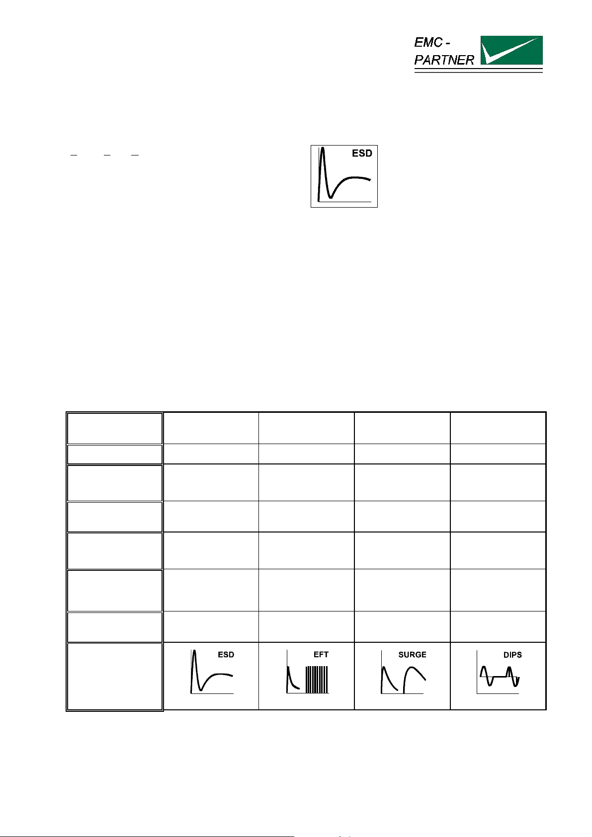
1.1.1 Electrostatic discharge ESD
Electro Static Discharge
Figure: 1.0.2
What causes electrostatic discharges?
A person becomes electrostatically charged by walking over an insulating floor surface. The capacity of the
body can be charged to several kilovolts (1000 V). This capacity is discharged when contact is made with an
electronic unit or system. The discharge is visible as a spark in many cases and can be felt by person
concerned, who gets a „shock“. The discharges are harmless to humans, but not to sensitive, modern
electronic equipment. The resulting current causes interference in the units or makes entire systems
„crash“.
For over 25 years it has been known to the electrical industry that electrostatic discharges as encountered
every day can have a disastrous effect on electronic equipment.
The cost of damage caused by ESD is difficult to assess, but amounts to billions of dollars world-wide.
The areas most affected are:
• manufacturing of integrated circuits (chips).
• the chemical industry, e.g. by explosion, fires caused by the sparks from electrostatic discharges.
• malfunctioning of process control with the secondary damage costs. characteristics
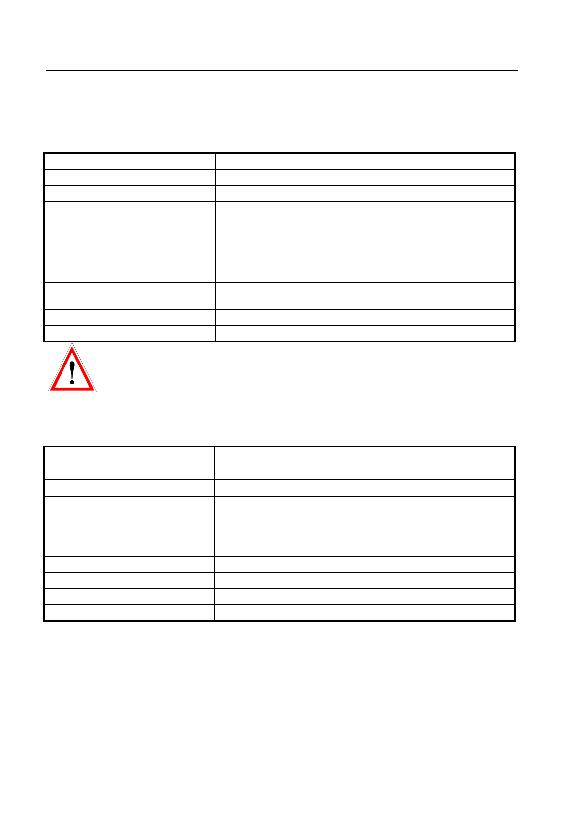
1.1.2 How ESD, EFT, SURGE, DIPS differ
Characteristics Static discharges Switched
inductance
Phenomenon
Voltage U
"ESD" "EFT Burst" "Surge" "DIPS"
up to 15 kV up to 4 kV up to 4 kV supply source
Energy at maximum
approx. 10 mJ 300 mJ 300 J -
Lightning.
switching actions
Mains
Interruptions
voltage
voltage
Repetition rate
Application to the
different ports
Single event Multiple event 5 kHz Maximum 6
Impulse / minutes
Touchable metallic
part ( enclosure
AC/DC ports, Signal
and data lines
AC/DC ports, Signal
and data lines
supply source
frequency
AC/DC ports
ports)
upper limit
approx.. 1 GHz approx. 200 MHz approx. 350 kHz approx. 100 kHz
frequency
impulse waveform
IEC 61000-4-2
IEC 61000-4-4
IEC 61000-4-5
IEC 61000-4-11
The overview of „How ESD,EFT, SURGE, DIPS differ“ shows that all four test have to be carried out
because the frequency content and energy of the four transient tests are different.
E-ESD3000-E-Manual.doc 7/66
Page 8
ESD3000-System
1.2 Technical data of the ESD3000 and DM Discharge Modules
1.2.1 ESD3000 equipment
Supply batteries NIMH standard UM-3/AA size
charging time (empty to full) ca. 5 hours
Polarity positive, negative; alternate
Number of discharges
Detection of the number of
discharges
Ramps voltage amplitude changes from shot to shot,
Reporting test sequence with the number of
Discharge modes: see list below
Repetition of the discharges 0.05 up to 30 s or single discharge „Man“
-preselectable
-count „all“, -count „discharge“. Only the
impulses whereas the voltage of the
discharge capacitor tropes lower then 10%
of the charging voltage are counted.
discharges, voltage amplitude, polarity
1 to 29’999
Only possible with
control form PC
Note: The repetition rates are applicable to IEC 61000-4-2 only. For all other modules or
applications consult the relevant DM (Discharge Modules) or DN (Discharge Network) specific Instruction
sheets.
1.2.2 Discharge Module ESD3000DM1 (IEC 61000-4-2 and EN61000-4-2)
Energy storage capacitance 150 pF ± 10%
Discharge resistance
Charging resistance
Holding time (drop to 95%) better than 5 s
Current rise time, 2 Ω load
First current amplitude into 2 Ω
„contact discharge“
Current amplitude at 30 ns 4 to 16 A ± 30%
Current amplitude at 60 ns 2 to 8 A ± 30%
Voltage range „air discharge“ 0.2 to 16 kV ± 10%
Voltage range „contact discharge“ 0.2 to 10 kV ± 10%
330 Ω
54 MΩ
0,7 to 1 ns
7,5 to 30 A ± 10%
± 10%
8/66
Page 9
ESD3000-System
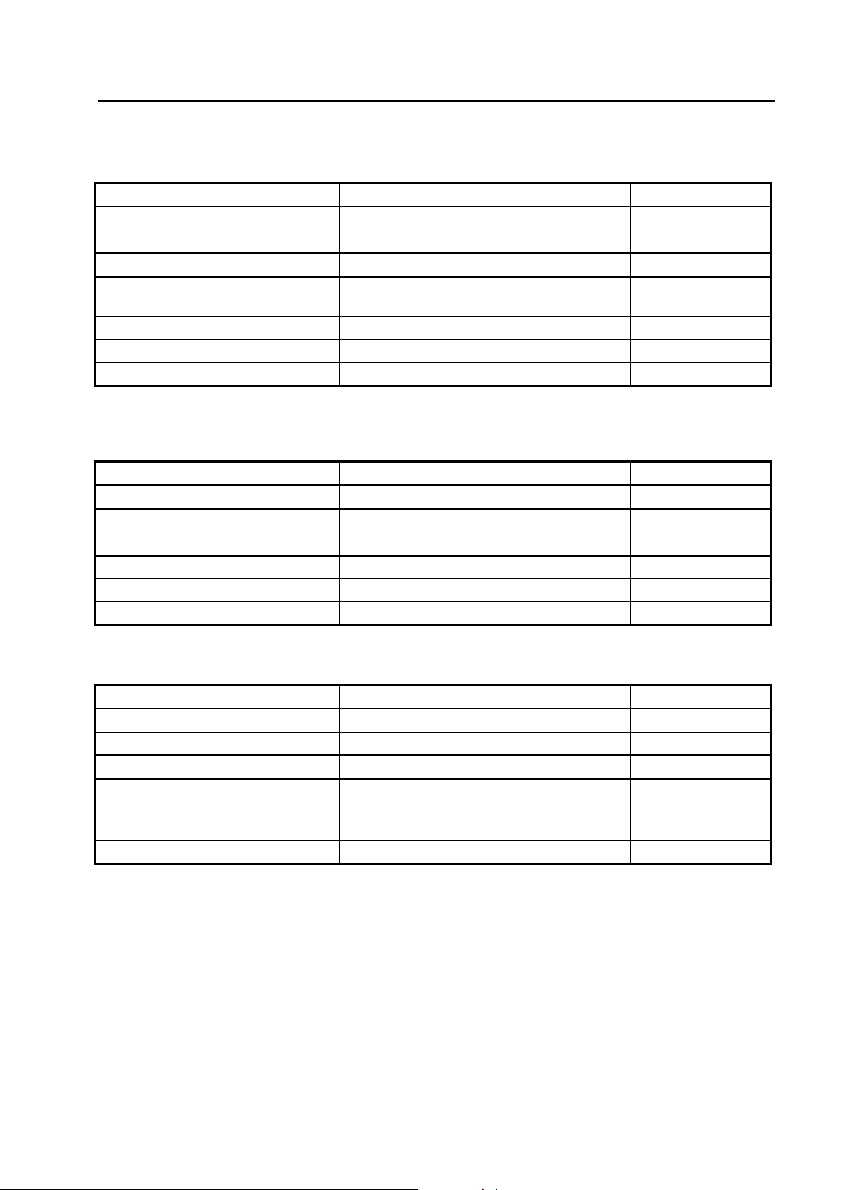
1.2.3 Discharge Module ESD3000DM2 (ISO TR10605 - inside vehicle, module tests)
Energy storage capacitance 330 pF ± 10%
Discharge resistance
2000 Ω
± 10%
Holding time (drop to 95%) better than 5 s
Current rise time, 2 Ω load
First current amplitude into 2 Ω
0,7 to 1 ns
7,5 to 30 A ± 10%
„contact discharge“
RC time constant 600 ±130ns
Voltage range „air discharge“ 0.2 to 16 kV ± 10%
Voltage range „contact discharge“ 0.2 to 10 kV ± 10%
1.2.4 Discharge Module ESD3000DM4 (MIL-STD-883E, MIL-STD-464, GR78-CORE)
Energy storage capacitance 100 pF ± 10%
Discharge resistance
1500 Ω
± 10%
Holding time (drop to 95%) better than 5 s
Current rise time, 2 Ω load
<10 ns at - 4 kV
Peak current 3.33 A at 5 kV
Voltage range „air discharge“ 0.2 to 16 kV ± 10%
Voltage range „contact discharge“ 0.2 to 10 kV ± 10%
1.2.5 Discharge Module ESD3000DM5 (RTCA/DO 160)
Energy storage capacitance 150 pF ± 10%
Discharge resistance
330 Ω
± 10%
Holding time (drop to 95%) better than 5 s
Current rise time, 2 Ω load
<5 ns at 15 kV
RC time constant 50 ns
Voltage setting accuracy ± 10% for voltages greater than 5 kV and ±
500 V for voltages lower than 5 kV
Voltage range „contact discharge“ 1 to 30 kV ± 10%
9/66
Page 10
ESD3000-System
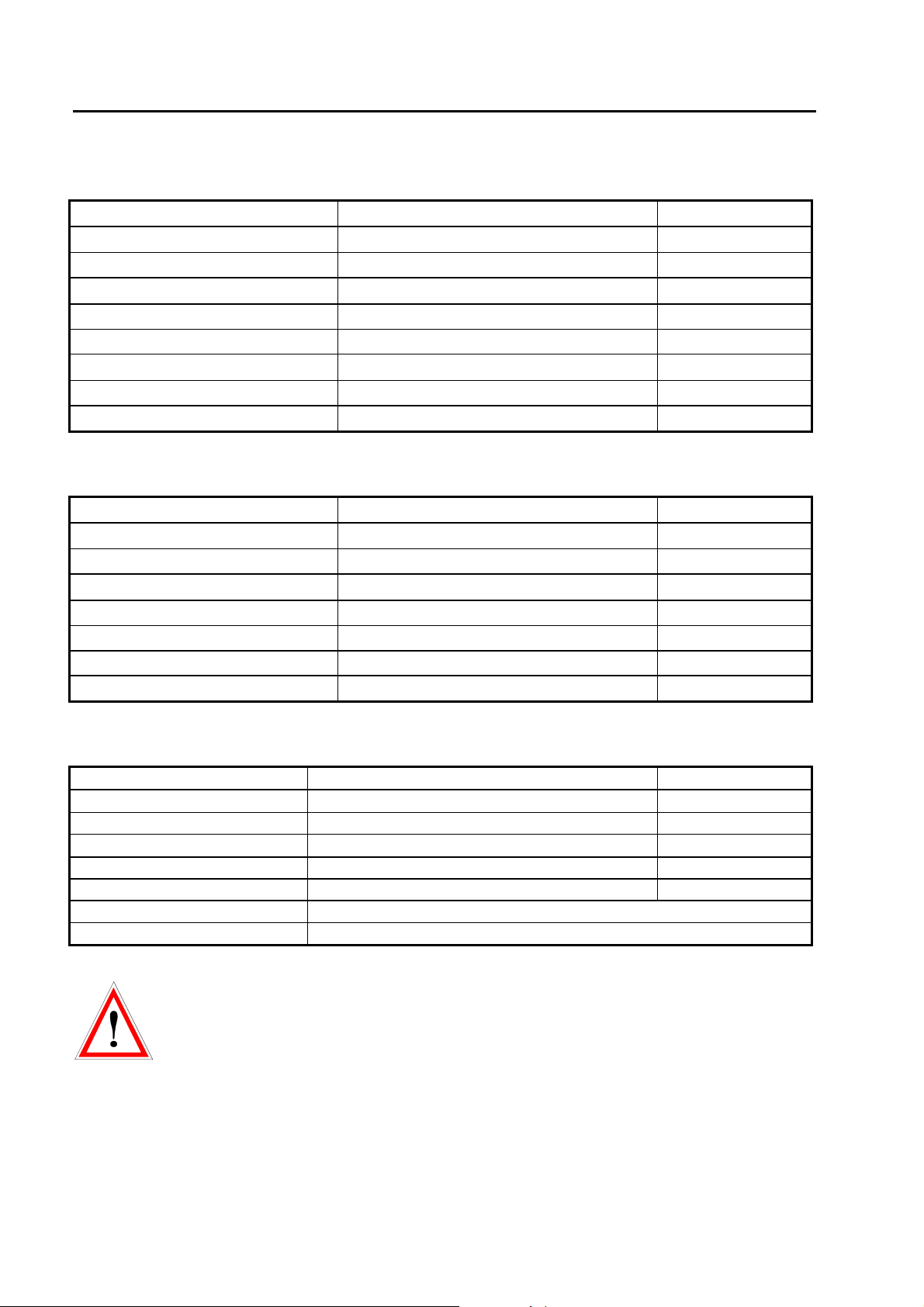
1.2.6 Discharge Module ESD3000DM6 (IEC 61340-3-1, JEDEC 22-A114, MIL-STD-750D9)
Energy storage capacitance 100 pF ± 10%
Discharge resistance
1500 Ω
± 10%
Discharge mode only contact discharge
Current rise time, 50 Ω load
2 to 10 ns
RC time constant 150 ns
Voltage range 200 V up to 10000 V
Voltage rise time, 500 Ω load
5 to 25 ns
Voltage verification V charging1000V 375 up to 550 V
Voltage range 200 V up to 8000 V
1.2.7 Discharge Module ESD3000DM7 (IEC 61340-3-2, JEDEC 22-A115)
Energy storage capacitance 200 pF ± 10%
Discharge resistance
500 Ω
± 10%
Discharge mode only contact discharge
Current waveform, short circuit <1 Ω
First peak to second peak 67% to 97%
oscillation period 63 ns up to 91 ns
Voltage verification V charging 400V first peak <1.31 A
Voltage verification V charging 400V amplitude at 100 ns 0.29 A -15%
Voltage range 80 V up to 2500 V
1.2.8 Discharge Module ESD3000DM8 (IEC 60571, EN 50155)
Waveform B Risetime 10/90% < 0.05 µs
Half value time 50 % to 50%
0.1 µs ± 20%
Voltage amplitude > 8400 V
Series Resistor (Rs)
100Ω ± 10%
Dimension / Weight l = 120, diameter = 60 mm 0.5 kg
Pulse Repetition Maximum 1 Hz
Required equipment ESD3000 + DM8
Voltage amplitude CD 200V up to 10’000V CD = Contact Discharge
Further Information to additional discharge modules DM or discharge networks DN can be
found in the relevant instruction sheets. or in the ESD3000 brochure.
10/66
Page 11
ESD3000-System
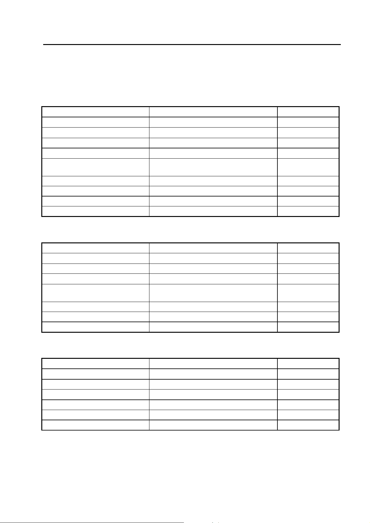
1.3 Technical data of the ESD3000RM and DN Discharge Networks
For all DN network the ESD3000RM relay module is necessary.
Discharge network ESD3000DN1 (IEC 61000-4-2 and EN61000-4-2)
Energy storage capacitance 150 pF ± 10%
Discharge resistance
Charging resistance
Holding time (drop to 95%) better than 5 s
Current rise time, 2 Ω load
First current amplitude into 2 Ω
„contact discharge“
Current amplitude at 30 ns 4 to 16 A ± 30%
Current amplitude at 60 ns 2 to 8 A ± 30%
Voltage range „air discharge“ 1 to 30 kV ± 10%
Voltage range „contact discharge“ 1 to 30 kV ± 10%
1.3.1 Discharge Network ESD3000DN2 (ISO TR10605 - inside vehicle, module tests)
330 Ω
54 MΩ
0,7 to 1 ns
7,5 to 30 A ± 10%
± 10%
Energy storage capacitance 330 pF ± 10%
Discharge resistance
Holding time (drop to 95%) better than 5 s
Current rise time, 2 Ω load
First current amplitude into 2 Ω
„contact discharge“
RC time constant 600 ±130ns
Voltage range „air discharge“ 1 to 30 kV ± 10%
Voltage range „contact discharge“ 1 to 30 kV ± 10%
1.3.2 Discharge network ESD3000DN3 (ISO TR10605 -outside vehicle, sensitive classification)
Energy storage capacitance 150 pF ± 10%
Discharge resistance
Holding time (drop to 95%) better than 5 s
Current rise time, 2 Ω load
RC time constant 300 ±60ns
Voltage range „air discharge“ 1 to 30 kV ± 10%
Voltage range „contact discharge“ 1 to 30 kV ± 10%
2000 Ω
0,7 to 1 ns
7,5 to 30 A ± 10%
2000 Ω
5 ns at + 15 kV
± 10%
± 10%
11/66
Page 12
ESD3000-System
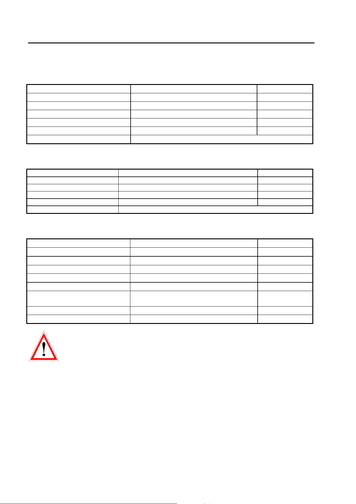
1.3.3 Discharge Module ESD3000DN4 (MIL-STD-883E, MIL-STD-464, GR78-CORE)
Technical data
Voltage contact up to 30 kV
Capacitance DN4 500 pF
Serial resistor DN4 5000 Ohm
Weight incl. accessories 0.8 kg
Standard MIL-STD 1512
Standard VG 95378
Usable with testers ESD3000, ESD3000RM32
1.3.4 Discharge Module ESD3000DN5 (MIL-DLT-23659D, STANAG 4239, MIL-STD 331)
Technical data
Voltage contact up to 30 kV
Capacitance 500 pF
Serial resistor 500 Ohm
Weight incl. accessories 0.8 kg
Standard customised
Usable with testers ESD3000, ESD3000RM32
1.3.5 Discharge Module ESD3000DN6 (MIL-DLT-23659D, STANAG 4239, MIL-STD 331)
Technical data
Energy storage capacitance 330 pF ± 10%
Discharge resistance
Charging resistance
330 Ω
54 MΩ
± 10%
Holding time (drop to 95%) better than 5 s
Current rise time, 2 Ω load
0,7 to 1 ns
Voltage range „contact discharge“ 1 to 30 kV ± 10%
First current amplitude into 2 Ω „air
< 5ns
discharge“
RC time constant 300 ns ± 60ns
Voltage range „air discharge“ 1 to 30 kV ± 10%
Further Information to additional discharge modules DM or discharge networks DN can be
found in the relevant instruction sheets. or in the ESD3000 brochure.
12/66
Page 13
ESD3000-System
1.4 Mechanical dimensions
Tester -Type Dimensions [mm] Weight [kg] Versions
width x depth x height
ESD3000 350 x 70 x 200 0.7 19" 4 UH
Discharge Module DM 550 x 600 x 190 0.35 19" 4 UH
The weight slightly differ a little bit from module to module
1.5 Power Consumption
The power supply of the ESD3000 is 42 V d.c.
AD / DC adapter inputs 100 up to 240 V ( 50/60 Hz )
300 mA
Output of AC/DC Adapter 24 V 500 mA
± 10 %
13/66
Page 14
ESD3000-System
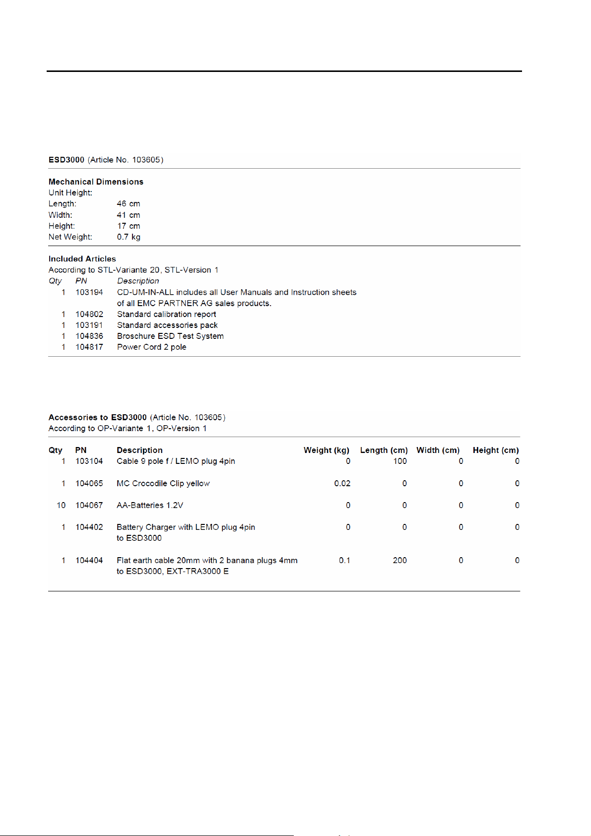
1.6 Accessories, dimensions
1.6.1 Included articles, dimensions
1.6.2 Standard accessories
14/66
Page 15
2 Safety
The ESD3000belongs to Safety class 1
2.1 Safety standard
The ESD3000 fulfils the requirements of the safety standards IEC 61010 for laboratory measurements
equipment „Safety requirements for electrical measuring, control and laboratory equipment“. Based on EN
61010 (IEC61010) the declaration of conformity to low voltage directive (LVD 73/23/EEC O.J.N° L77, 197303-26) is given.
This manual is a integral part of the ESD3000 tester. The instructions
contained in the manual regarding operation and the test set up are to
be strictly observed
2.2 Climatic Conditions
The ESD3000 contains high voltage circuits in integrated form. EMC PARTNER only guarantees a correct
functioning of the tester ESD3000 and the associated accessories, if the ESD3000 is operated in the
climatic condition specified.
Temperature 15 °C to 35 °C Charging voltage up to 25 kV
Relative humidity 10 % to 60 % Charging voltage up to 25 kV
Atmospheric pressure 86 kPa to 106 kPa
(860 to 1060 mbar)
Atmospheric condition Voltages > 25 kV
Contact discharge not influenced by: direct solar radiation, rain or condense water, dust or larger
electro magnetic fields as specified in the EMC compatibility
chapter.
The ESD3000 should be operated in a dry, clean room. If for any reason water condenses in the ESD3000,
then no operation should be started before the tester is dry.
It is strictly forbidden to operate the ESD3000 in rooms with of gas explosion risk.
The high voltage of the ESD3000 generate sparks, which can ignite the gas.
People with heart pacemakers should not be in the vicinity of the test set up during operation.
20°C, RH 30%, pressure 101.3 kPa
Charging voltage up to 25 kV
E-ESD3000-E-Manual.doc 15/66
Page 16
ESD3000-System
2.3 Precautionary measure during use
The ESD3000 generates high voltages. The energy content of the 30 kV modules is high
and can be dangerous with improper use. It is wise to observe the following rules
• Never touch the EUT when a test is in operation.
• Touch no connectors of connection cable or tips when a EMC test is in operation.
• The high voltage of the ESD3000 and the power on the EUT must turned off before a manipulation on
the EUT is carried out.
• For all tests the 2 m ground cable must be connected to ground.
2.4 Electromagnetic Compatibility
The outputs of the ESD3000 and the discharge to the EUT will emit disturbances.
Please consider the national emission rules.
The Test System ESD3000 should not be operated near sensitive measuring and
control systems.
The ESD3000 fulfils the following immunity requirements
• Electrostatic discharge
Level 4 (8 kV) (IEC 61000-4-2)
2.5 The manual is an integral part of the equipment. Refer to the manual.
This manual is an integral part of the ESD3000. The safety rules and precautions in the manual must
be observed. EMC PARTNER and their representatives are not responsible for damage to persons
and equipment by not observance the safety rules and precautions in the manual.
2.6 No operation of ESD3000 without ground wire
The ESD3000 must be operated with a ground wire attached to the battery case
16/66
Page 17
3 Mechanical structure
3.1 General
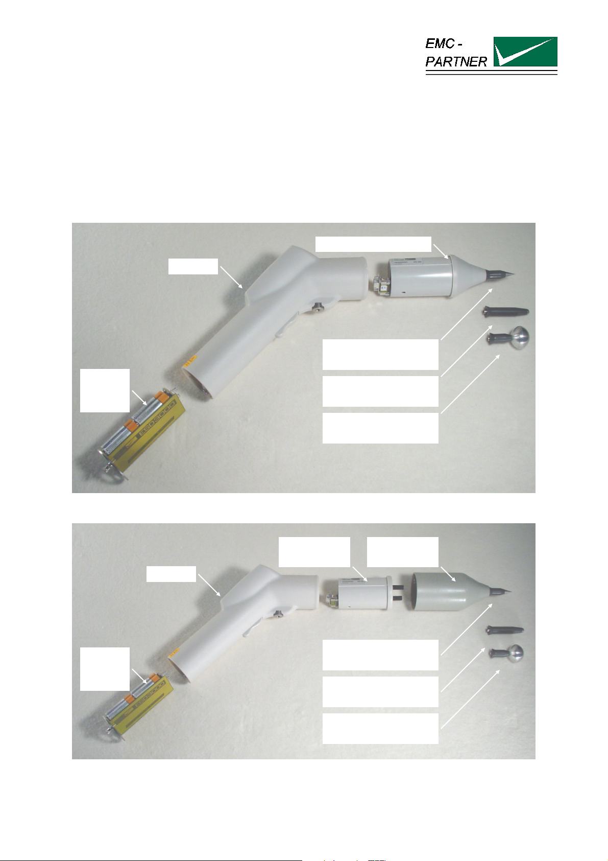
The battery operated ESD3000 is ideal for running tests in development/test laboratory environments and
for outdoor service on larger systems.
3.2 Overview on ESD3000 system
3.2.1 ESD3000 Contact Discharge (CD) up to max. 10kV with Discharge Module (DM )
Discharge Module (DM)
ESD3000
Sharp Tip for
contact discharge (CD)
Batteries
standard
VM size 3
3.2.2 ESD3000 Contact Discharge (CD) up to max. 30kV with (RM and (DM )
Discharge
Network (DN)
ESD3000
Batteries
standard
VM size 3
Rounded Tip for
air discharge (AD)
30 mm Tip Electrode for
(AD) V > 16 kV
Relay Module
(RM)
Sharp Tip for
contact discharge (CD)
Rounded Tip for
air discharge (AD)
30 mm Tip Electrode for
(AD) V > 16 kV
ESD3000 Contact Discharge (CD) up to 30 kV) with Relay Module (RM), Discharge Network (DN)
E-ESD3000-E-Manual.doc 17/66
Page 18
ESD3000-System
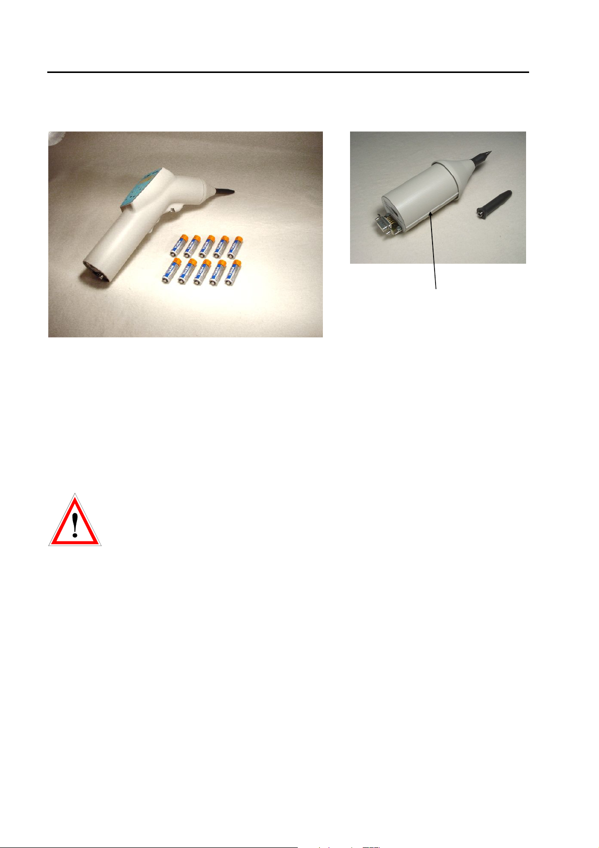
The ESD test System consist of ESD3000, the discharge modules (DM) or relay module and networks.
The batteries, the charger and control are part of ESD3000. The discharge modules or networks includes
the high voltage generation and the wave-shaping network.
Positioning part of the
discharge modules
ESD3000 with one discharge module Discharge Module
The screw on the bottom side of the ESD3000 must be unscrewed, before the DM can be pull out and
changed with an other one. The modules can be inserted only in one position.
3.2.3 Avoiding Mechanical Damage to Discharge Modules
ESD3000 discharge modules contain components sensitive to mechanical shock. When modules suffer
mechanical shock they can be damaged beyond repair.
When ESD3000 modules are not in use, place them in the transport case. Do not
allow them to roll around on the test bench or fall onto the floor.
18/66
Page 19
4 Control Panel
4.1 Front panel of the ESD3000
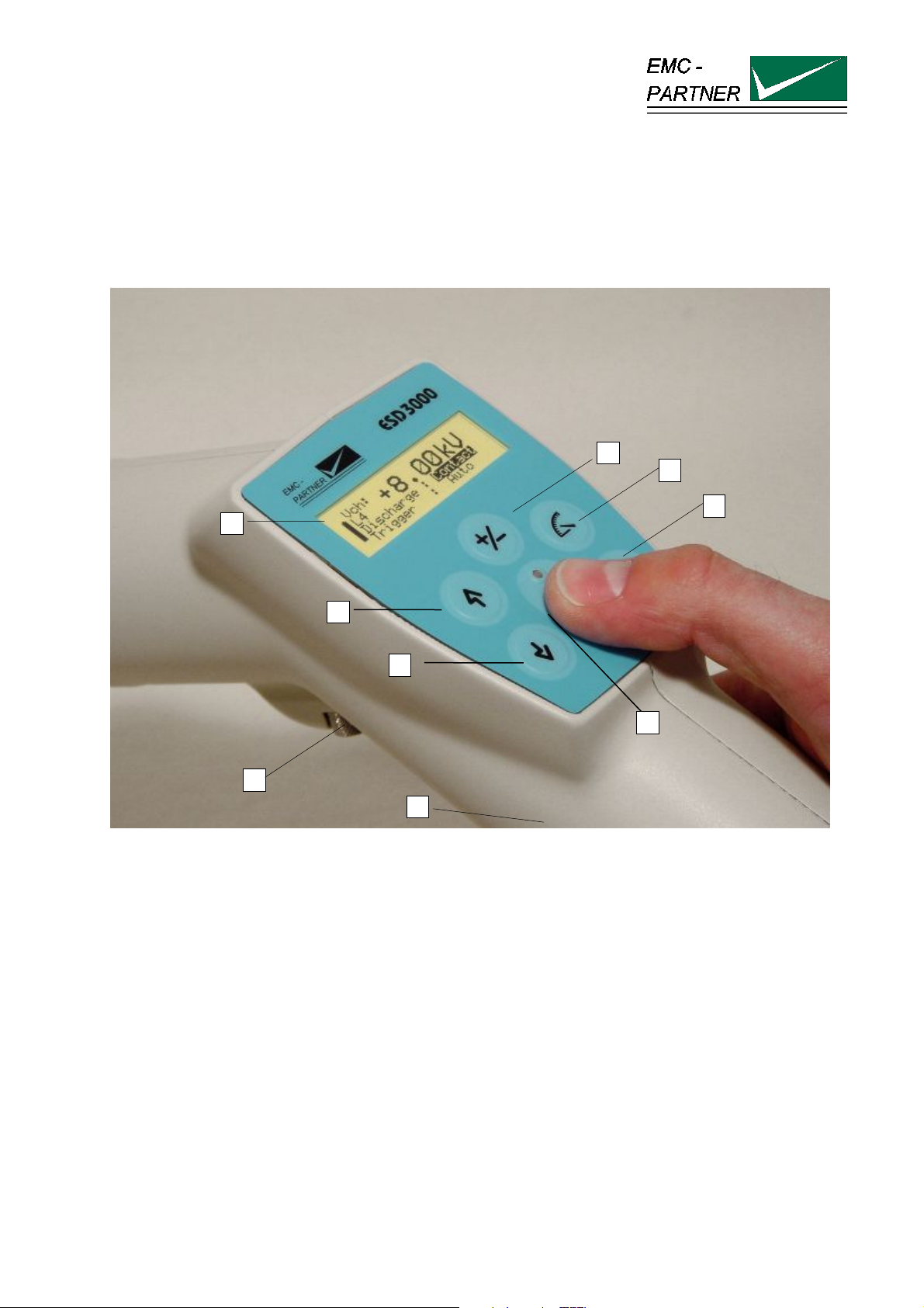
The operator should study the manual in detail. Only instructed personal is allowed to operate the ESD3000.
7
6
5
1
2
3
4
8
9
The most important elements of the front panel are:
1. Display
2. Voltage up or menu command line up
3. Voltage down or menu command line down
4. Run button: With the „Run“ button, a test can be started or interrupted. With the run button the unit is
turned „ON“
5. Enter
6. Selection of the programmed test levels. The programmed test levels changes with discharge module
interchange
7. Polarity selection
8. Screw for looking the discharge modules. The same screw can be used for fix the ESD3000 on a
tripod stand.
9. Trigger button: When manual trigger is programmed and the tester is ready for manual trigger, this will
be signalled by the LED. As soon as the signal occurs the pulse can be released.
E-ESD3000-E-Manual.doc 19/66
Page 20
ESD3000-System
4.2 Interchange of discharge modules
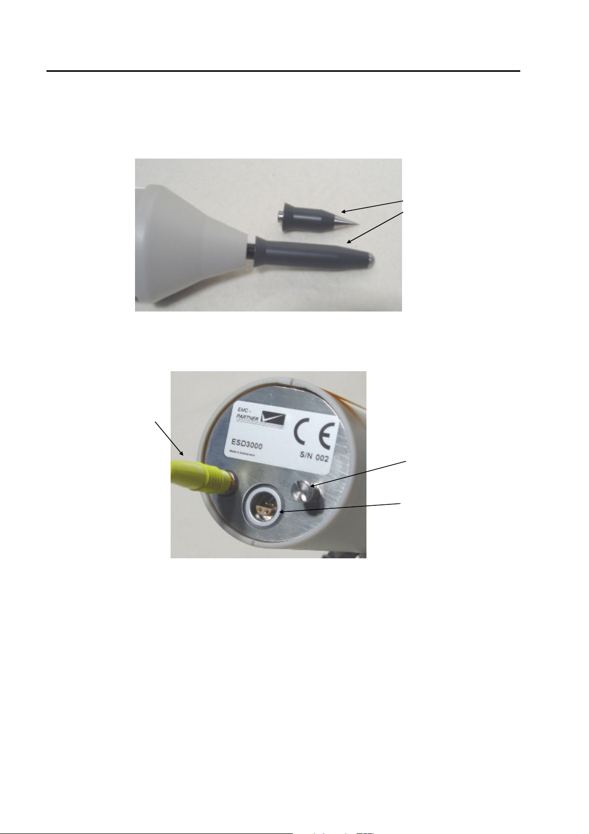
Loose the screw 8 and pull the discharge module out.
4.3 Interchange of the finger and tips
4.4 Inputs and Outputs
Ground connection 2 m
Pull out the finger and
insert the tip
CD = sharp tip
AD = finger electrode
Screw holding the
battery module
Input for charging the
batteries, and RS232
input for remote control
The control of the ESD3000 is carried out by a microprocessor. The microprocessor controls the EMC tests,
stores the inputs of the numeric input terminal, updates the display, checks whether the inputs of the
operators are allowed values or not. The operator communicates with the ESD3000 via the input terminal
and the display.
This plate is reserved for the CE mark. The CE -mark is needed for the free movement of the goods into
and within European community.
Via this interface port, the ESD3000 can be also controlled by an external PC. To configure the interface,
see Chapter 13 „Remote Control“.
20/66
Page 21
5 Preparation for Operation
5.1 Attention, Refer to Manual
This manual is an integral part of the ESD3000. The safety rules and precautions in the manual must
be observed. EMC PARTNER and their representatives accept no responsibility not responsible for
damages to persons and equipment as a results of non-observation of the safety rules and
precautions in this manual.
5.1.1 ESD test set up
Ports which must be tested:
Enclosure Ports include operational keys, displays, ground and earth points, metallic parts such as
connector etc.
Coupling path:
Basically all types of coupling exists during static discharges. Practical experience shows that, for the most
electronic equipment, the current is the dominant parameter.
In practice the current path of the discharge current plays a important role e.g. if secondary sparks or
breakdown in the UET occur the test is no longer reproducible.
The frequencies contained in the ESD discharge current are higher than in the EFT spike impulse. As a
consequences, reproducibility of the ESD test is more difficult than the reproducibility of the EFT test results.
The ESD test is one of the most complex transient test.
Test set-up:
As shown by the example in the IEC document 61000-4-2 the same test set up can be used for all different
discharge mode (contact-, air- and indirect-discharge). Under the table lays the reference ground plan and
on the table is the horizontal coupling plane placed.
The test mode used depends on the test object.
The three different kinds of test object are:
Metallic equipment under test
EUT
I
II-<----<----<---- -----<----I I---------> --->---->---->--I
with contact possibility
I
I I I
I I I
I
I
I I I
Discharge directly contacted
with relay tip
direct discharge air discharge indirect discharge
Combination such as metal
case, insulated keyboard
I I I
with discharge----<-----<
I
without contact possibility
I
Air discharge with IEC finger.
Holding time 5 seconds.
voltage test with IEC finger and
Indirect test with coupling plane
Insulated EUT plastic, paint,
varnish
I
Vmax
without discharge
( breakdown)
and relay
E-ESD3000-E-Manual.doc 21/66
Page 22
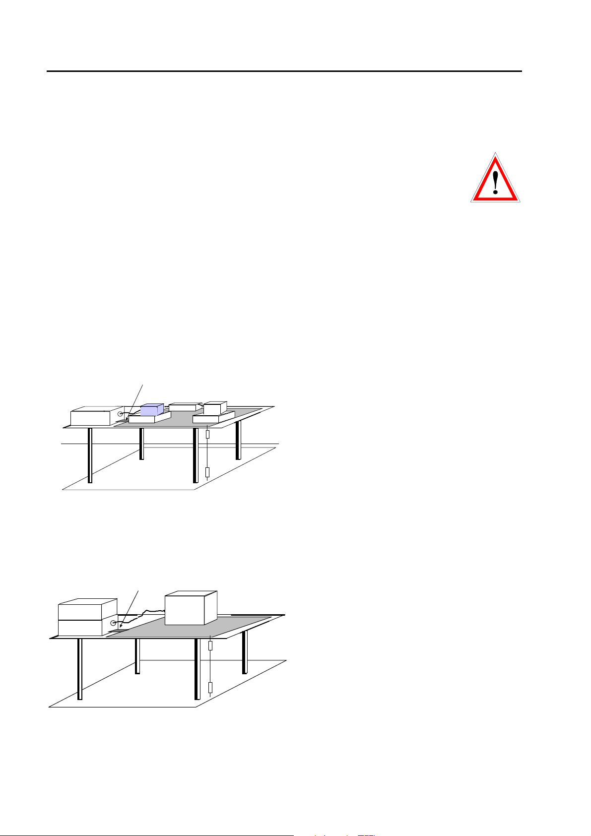
ESD3000-System
1
GRP
RP / HCP
GRP = Ground reference plane ESD
RP = Reference plane EFT
HCP = Horizontal coupling plane ESD
CNEFT = Coupling clamp for EFT
CDN-1000
1
GRP
RP / HCP
GRP = Ground reference plane ESD
RP = Reference plane EFT
HCP = Horizontal couplinge plane ESD
TRANSIENT2000
2x470k
EUT
The ESD transient test is a single event test. The susceptibility of an EUT is strongly influenced by the clock
frequency. With the clock frequency, the information will be transmitted in the EUT or to the auxiliary
equipment within a system. The ESD pulse enters the EUT when no information is being transmitted, the
EUT has a very good immunity to EMC test, whereas the equipment will fail in operation. The existing ESD
testers on the market the discharge cannot be synchronised with the clock frequency. Therefore the number
of shots must be increased up to 100 discharges.
Safety:
ESD3000 is not a toy. It is a professional tool and belongs only in the hand of specialists and appropriately
trained personnel.
The ESD3000 must no be switched „ON“ with the „RUN“ button unless a correctly connected earth or
ground cable is in place.
5.1.2 Test set-up for table top equipment
Test set up Test sequence
Single Phase EUT
I. EFT
1. Connect the earth bar of the TRANSIENT-2000
with the flat multiwire cable (1) to the reference
ground plate
2. Put 10 cm insulation between EUT and the
reference ground plate
3. Carry out the tests!
II. ESD
1. Remove the flat multiwire cable (1) between the
earth bar of the TRANSIENT-2000 and the
reference ground plate
2. Put 0,5 mm insulation between EUT and the
reference ground plate
3. Carry out the tests!
III. SURGE, DIPS, VARIATION
1. Reinstall the flat multiwire cable 1
2. Carry out the tests!
Three Phase EUT
I. EFT
1. As for single phase EUT
2. As for single phase EUT
3. Connect the Impulse out of the TRANSIENT
with EFT coupling on the Threephase
Coupling/De-coupling network CDN-2000-06-25
4. Carry out the tests!
II. ESD
1. As for single phase EUT
2. As for single phase EUT
3. Carry out the tests!
III. SURGE,
1. Make connection 1
2. Connect the surged phase for synchronisation
with EUT Power 1
3. Carry out the tests!
IV. DIPS Interruption
1. Loop the phase for dips and interruption
through the TRANSIENT-2000 (EUT Power 1)
2. Carry out the tests!
22/66
Page 23

ESD3000-System
5.2 Practical testing sequence
In practice, the following test procedure has been shown to be reliable:
1. Burst-Testing:
• Burst-testing on mains inputs with a test voltage of 4kV
• Burst-testing of signal and data lines up to 4kV
The energy contained in the burst pulses is relatively small, thereby minimising damage to the test object.
The higher the repetition frequency, the more likely it that weak points become evident in the test object.
2. ESD-Testing:
With this test, effects induced through the keys and the housing of electronic equipment can be simulated.
• Metallic parts, contacted method up to 8 kV
• Insulated parts, air discharge up to 15 kV
In practice, an item that has undergone burst testing shows a better immunity to ESD, than one which has
not. Likewise, an item that has undergone burst testing shows a better immunity to current injection or cw
field tests.
3 Surge-testing:
• Surge testing mains up to 2 kV
This should be used to test input protection elements and protection circuits installed in electronic
equipment. The energy content is very high in the surge test, and can destroy elements in the EUT.
• Surge testing signal and data lines up to 1 kV
4 Mains simulation:
As a consequence of the increasing number of non-linear loads, the quality of the mains gets worse and
worse. To be sure that electronic equipment can withstand the mains interference, test are such as:
Mains interruption, Mains under and over voltage variation, harmonics simulation etc. are required.
5 Further testing:
For most EUT, the described transient tests are sufficient. Further testing of the product to determine
differences, e.g. with regards to the effects of magnetic field on monitors or on protection elements, may be
needed.
Conclusion:
The product determines which kind of EMC test must be applied. It is also important, that EMC testing
should only be carried out by trained personnel, with a knowledge of how the test object should function, and
some knowledge of transients and EMC. The four tests, with their range of impulse types, simulate only
single signals, and do not cover the complete range of EMP phenomena. However, if no more failures were
registered, after a period of EMC testing with electronic equipment and systems in practical operation, it
would not be justified to impose additional EMC tests.
Further EMC test information can be obtained from EMC Partner or from our representatives.
23/66
Page 24

ESD3000-System
24/66
Page 25
6 Testing with the ESD3000
6.1 Contact discharge
When you have studied Chapter 2 „Safety“ and Chapter 5 „Preparation for operation“ and all instructions
have been followed you have green light for a quick start..
EMC PARTNER store the needed tests specified in the basic standard in the ESD3000 before shipping.
To carry out a contact discharge, the following steps must be carried out:
• Connect correctly the earth or ground cable to a laboratory supply earth point or to a earth point of the
EUT.
• The discharge module must be equipped with the sharp tip
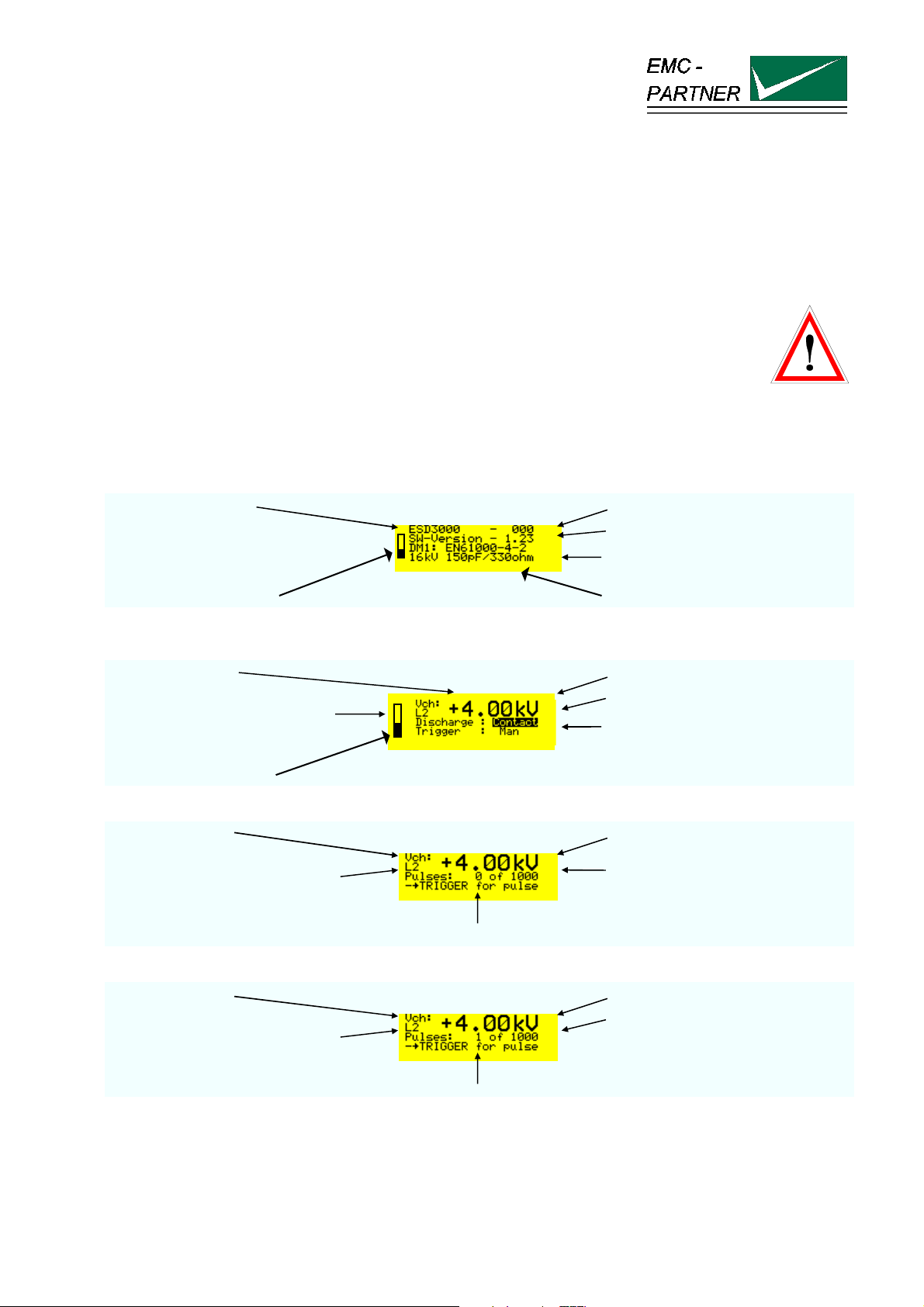
• Operate the „RUN“ button on the front panel the display turns to the EMC PARTNER logo and after a
second to:
test generator type serial number
software version
main parameter of the DM
batteries charge status inserted discharge module DM
Press the „RUN“ button one more time and the display turns to:
charging voltage polarity positive and voltage in kV
voltage level selected L2 = 4 kV
activated discharge mode
trigger mode manual
batteries charge status
Press the „RUN“ button one more time and the display turns to:
charging voltage charged voltage
voltage level selected L2 = 4 kV
first number indicates how many
pulses are released and second
number „how many pulses can be
carried out before the tests stops
TRIGGER button must be pressed
When the TRIGGER button has been pressed :
charging voltage charged voltage
voltage level selected L2 = 4 kV
first number change to 1. The first
ESD with 4 kV has been occurred
TRIGGER button must be pressed
Press the „RUN“ button and the ESD3000 return to the main setting mode.
E-ESD3000-E-Manual.doc 25/66
Page 26
ESD3000-System
6.2 Air discharge
To carry out a air discharge, the following steps must be carried out:
• Connect correctly the earth or ground cable to a laboratory supply earth point or to a earth point of the
EUT.
• The discharge module must be equipped with the finger tip
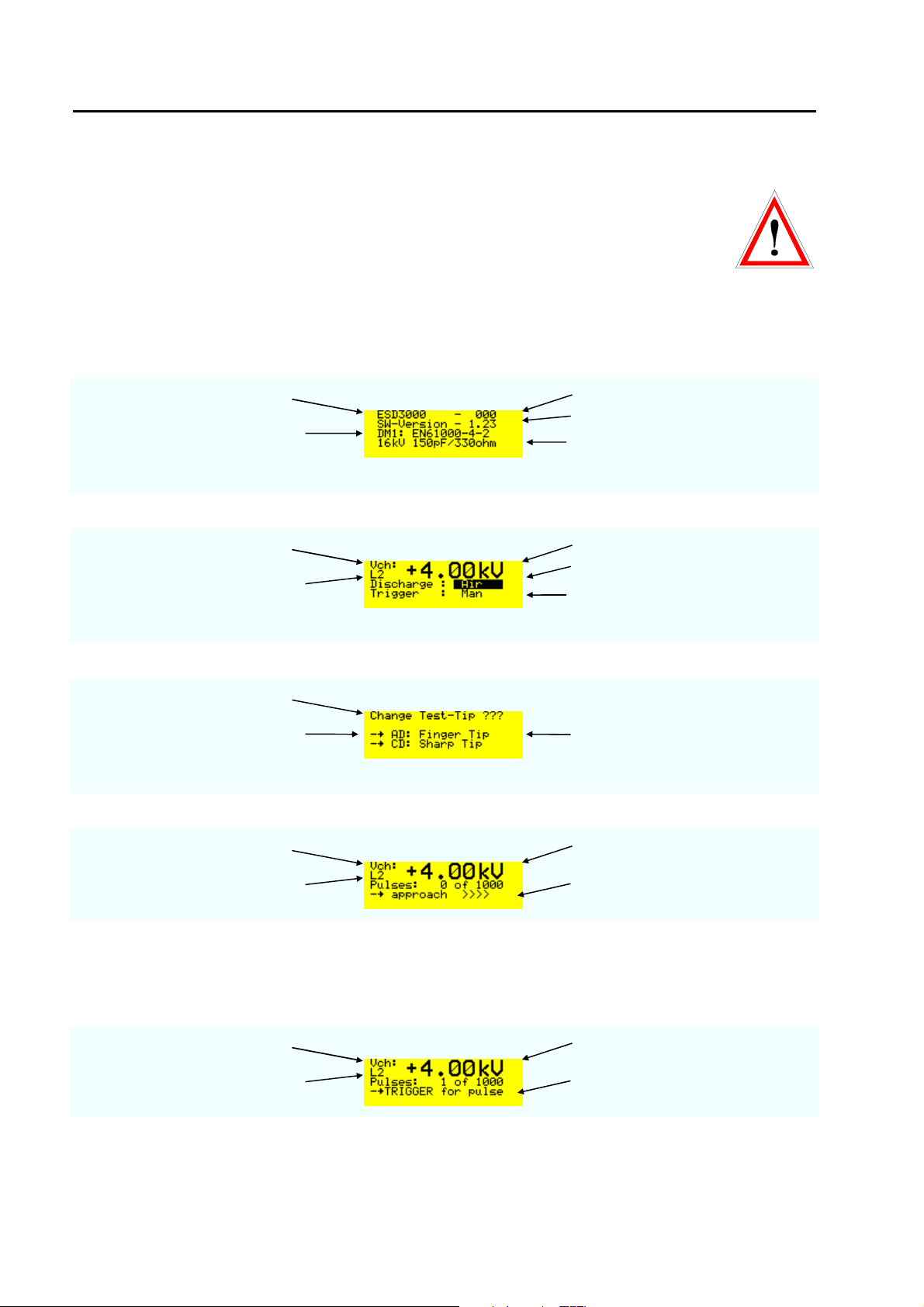
• Press the „RUN“ button on the front panel and the display turns to the EMC PARTNER logo and after a
second to:
test generator type serial number
inserted discharge module DM
software version
main parameter of the DM
Press the „RUN“ button one more time and the display turns to:
charging voltage polarity positive and voltage in kV
voltage level selected L2 = 4 kV
press ENTER button and the
display change contact to air
trigger mode manual
Press the „RUN“ button one more time and the display turns to:
Information display
AD = air discharge,
CD = contact discharge
check whether the correct tip is
put on the DM, AD = air discharge,
CD = contact discharge
Press the „RUN“ button twice and the TRIGGER button once - the display turns to:
charging voltage charged voltage
voltage level selected L2 = 4 kV
The air discharge must occurred
before 5 s are over
As soon as „approach >>>>“ is indicated on the display, the finger can be moved against the EUT. For the
movement against the EUT a maximum of 5 Seconds are reserved, corresponding to the holding time in the
IEC standard. For ISO 10605 test on insulated equipment press the Trigger button a second time when the
15 mm position is reached. This will avoid second air discharges.
Press the „RUN“ button - the display turns to:
charging voltage selected voltage level
voltage level selected L2 = 4 kV
first number change to 1. The first
ESD with 4 kV has been occurred
Press the „RUN“ button and the ESD3000 will be in the main setting mode.
26/66
Page 27
ESD3000-System
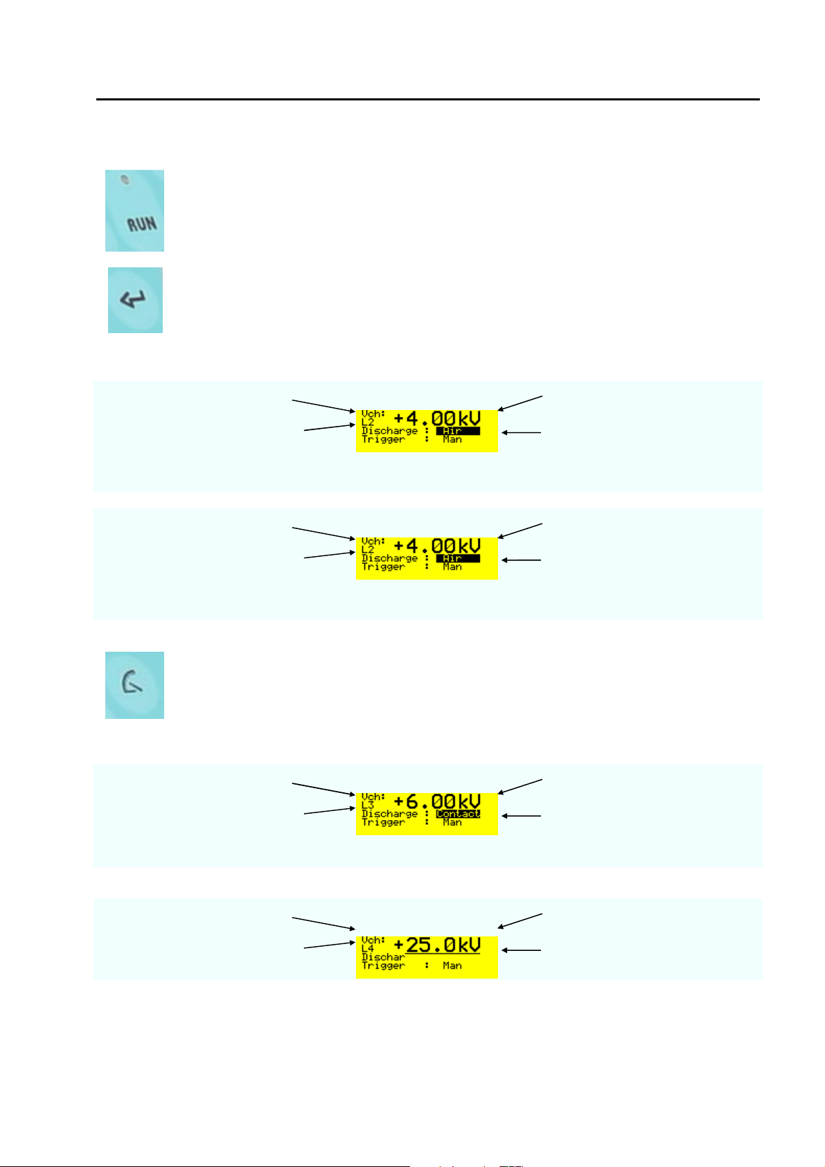
6.3 Main parameter setting with the buttons on the front plate
RUN
this button has different functions:
• Turn „ON“ and „OFF“ the supply of the ESD3000
• Turn “ON“ and „OFF“ the high voltage in the discharge modules DM
• The blinking light above the „RUN“ button indicates „High Voltage ON“
ENTER
this button has different functions:
• Change the mode of the black cursor location
• Activate parameter in one line to vary the parameter with up and down
• Quit the selected parameter
Examples with ENTER button
charging voltage selected voltage level
voltage level selected L2 = 4 kV
When the black cursor is
positioned as showed and the
ENTER button is pressed, the
discharge change to „contact“
charging voltage selected voltage level
voltage level selected L2 = 4 kV
When the black cursor is
positioned as showed and the
ENTER button is pressed, the
trigger change to „Auto“
LEVEL
• With the button „level“ very quickly the test levels of different standards can
be selected.
• The test levels change in function of the DM discharge module inserted into
the ESD3000.
Examples with LEVEL button
charging voltage polarity and Voltage value
Wit discharge module DM1“
voltage level selected L3 = 6 kV
Examples with LEVEL button
charging voltage charged voltage
With discharge module DM3
voltage level selected L4 = 25 kV
27/66
Page 28
ESD3000-System
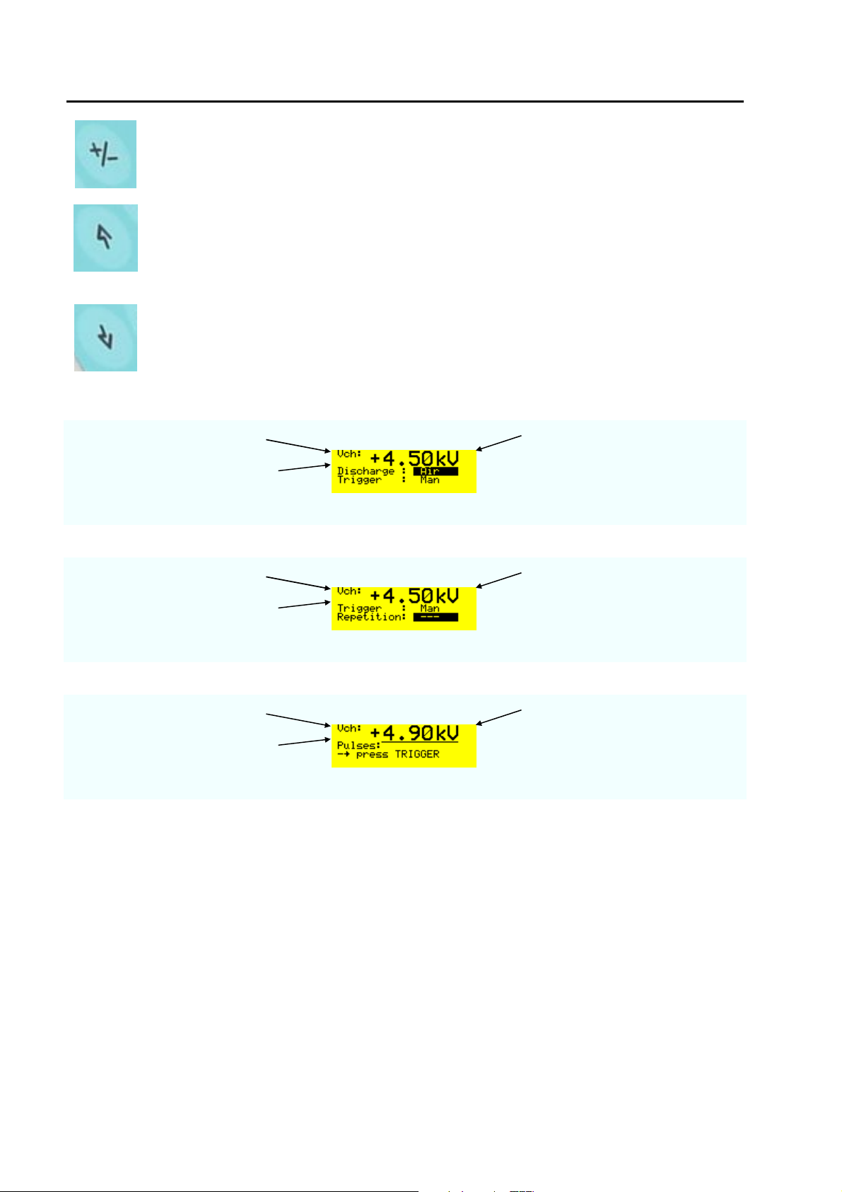
POLARITY
• Change the polarity of the charging voltage from positive to negative or from
negative to positive.
UP
this button has different functions:
• Change the charging voltage between the levels
• Moves the cursor in the menu up
• In the operation mode the charging voltage can be increased
DOWN
this button has different functions:
• Change the charging voltage between the levels
• Moves the cursor in the menu down
• In the operation mode the charging voltage can be decreased
Examples with charging voltage
charging voltage voltage increased to 4.5 kV
“
No level is indicated
Examples with menu
charging voltage Increased voltage 4.5 kV
Twice the button „down“ pressed
voltage level selected L2 = 4 kV
Examples with voltage changes in operation mode
charging voltage Increased voltage
No voltage level selected kV
RUN button pressed and with “up“
the voltage increased to 4.9 kV
Well that's easy isn't it ?
Most of the ESD tests can be done only using the hardware button on the front plate. In the next two
sections, the additional possibilities of the ESD3000 will be explained in detail.
28/66
Page 29
ESD3000-System
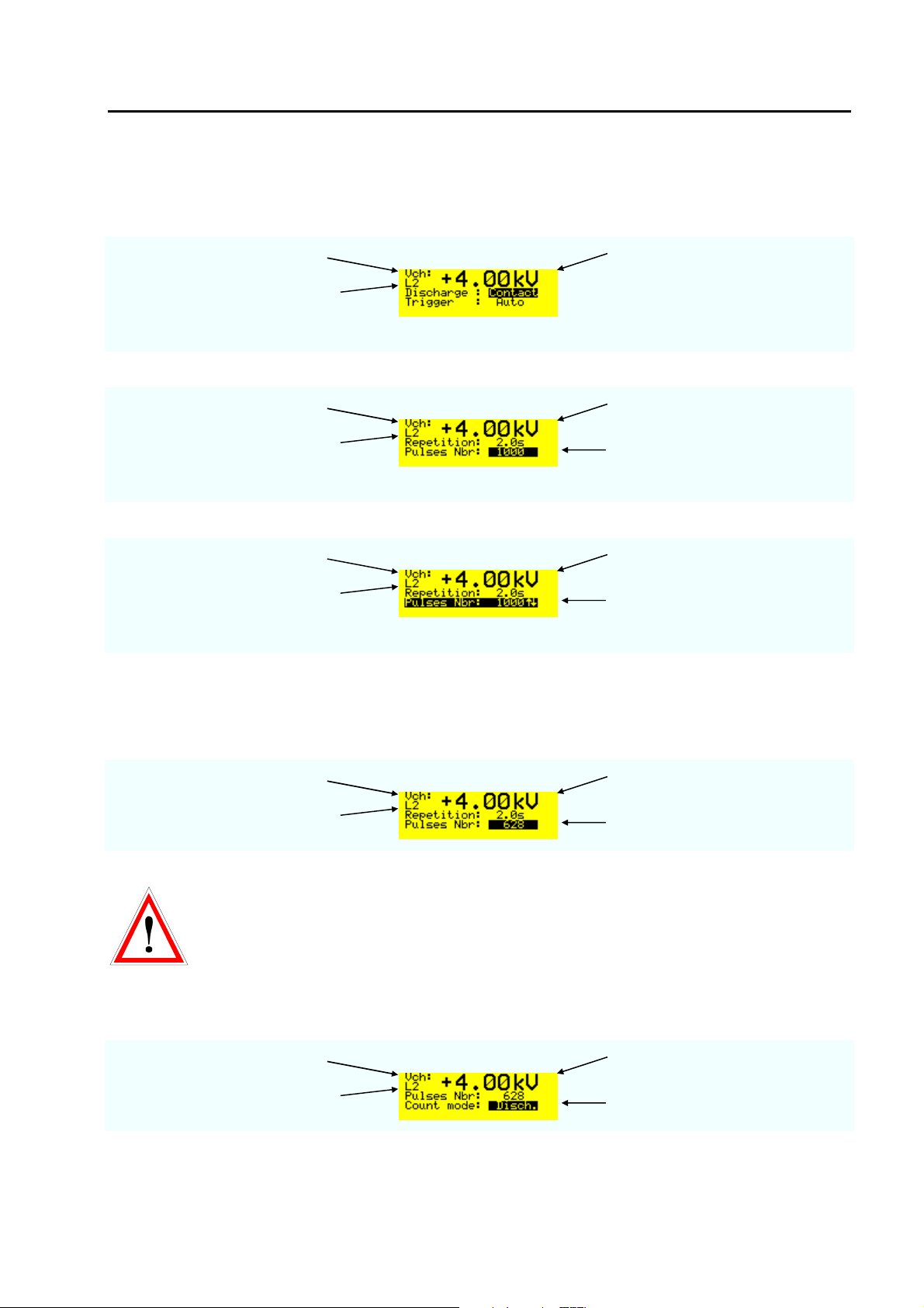
6.4 The different software menus of the ESD3000
6.4.1 Repetition, number of pulses, count mode
Number of pulses
charging voltage selected voltage level
voltage level selected L2 = 4 kV
When the „down button „ has been pressed twice - the display looks like:
charging voltage selected voltage level
voltage level selected L2 = 4 kV
When the „ENTER „ button has been pressed the displays turns to:
charging voltage selected voltage level
voltage level selected L2 = 4 kV
Remark: up to 1000 discharges steps are 1, over 1000 steps change to 1000. Holding the „UP“ or „DOWN“
button pressed, the steps changes from 1 to 10 or from slow to fast.
The „ENTER „ button must be pressed to quit the selected pulse number:
charging voltage selected voltage level
voltage level selected L2 = 4 kV
Repetition of the discharge pulses can be changed on same way as the pulse number. The repetition can
only for AUTO mode be selected. The repetition time can be selected from 0.05 (20 Hz) up to 30 seconds
The number of discharges can be
selected after the ENTER button
has been pressed
With the „UP“ and „DOWN“ button
the number of discharges can be
modified.
Selected number of discharges.
EMCP recommends to use the air discharge mode for week points exploration. The 20Hz
repetition reduce the life span of the high voltage relay. See chapter 6.5.1.2.
Count mode
After pressing „down „ with the „ENTER“ button the count mode can be selected
charging voltage selected voltage level
voltage level selected L2 = 4 kV
Selected count mode.
Remark: two count mode can be differed: „Disch.“ or „ALL“. In „All“ mode all released impulses will be
counted. In „Disch.“ mode only the real discharges are counted (current sensing).
29/66
Page 30
ESD3000-System
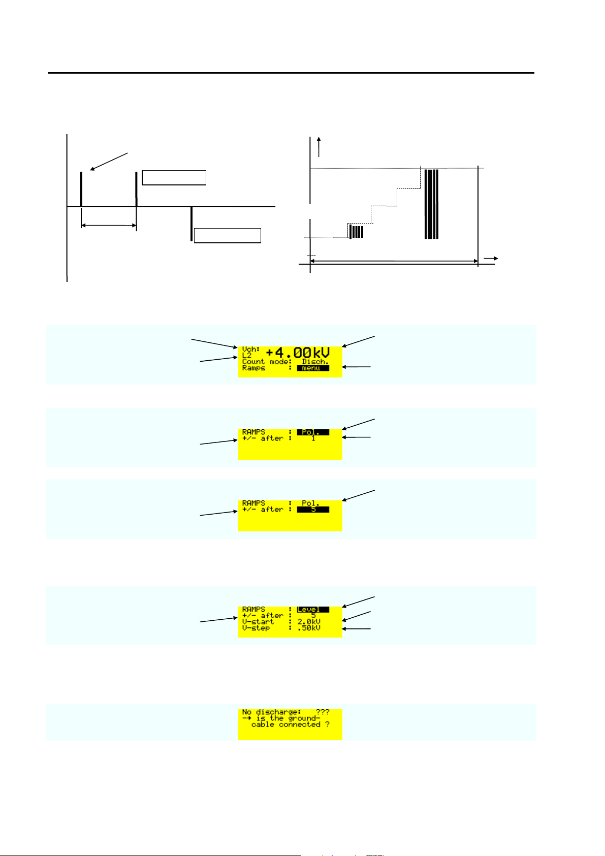
t
T
6.4.2 Menu „Ramps“
discharge
V
e.g. 10 pulses per step
polarity pos.
Start 2000V
repetition 1/T
polarity neg.
number of pulses
Polarity
charging voltage selected voltage level
voltage level selected L2 = 4 kV
Press the ENTER button to open
the „Ramps“ menu.
When the „ENTER“ button has been pressed twice the displays indicate:
Ramp polarity
Polarity change after the selected
number of pulses
Press the ENTER button to
change the number of pulses with
up or down
Ramp polarity
Polarity changes after 5 pulses
Voltage
When the „ENTER“ button has been pressed an additional once:
Ramp Level
Level changes after the selected
number of pulses
The ramp starts at this level
After 5 pulses the voltage will be
increased with 500 V
Remark: The maximum voltage is equal the nominal voltage or selected level 4 kV.
The following message will occur when after three releases no discharges was happen
Nominal
= 8000V
t
30/66
Page 31
ESD3000-System
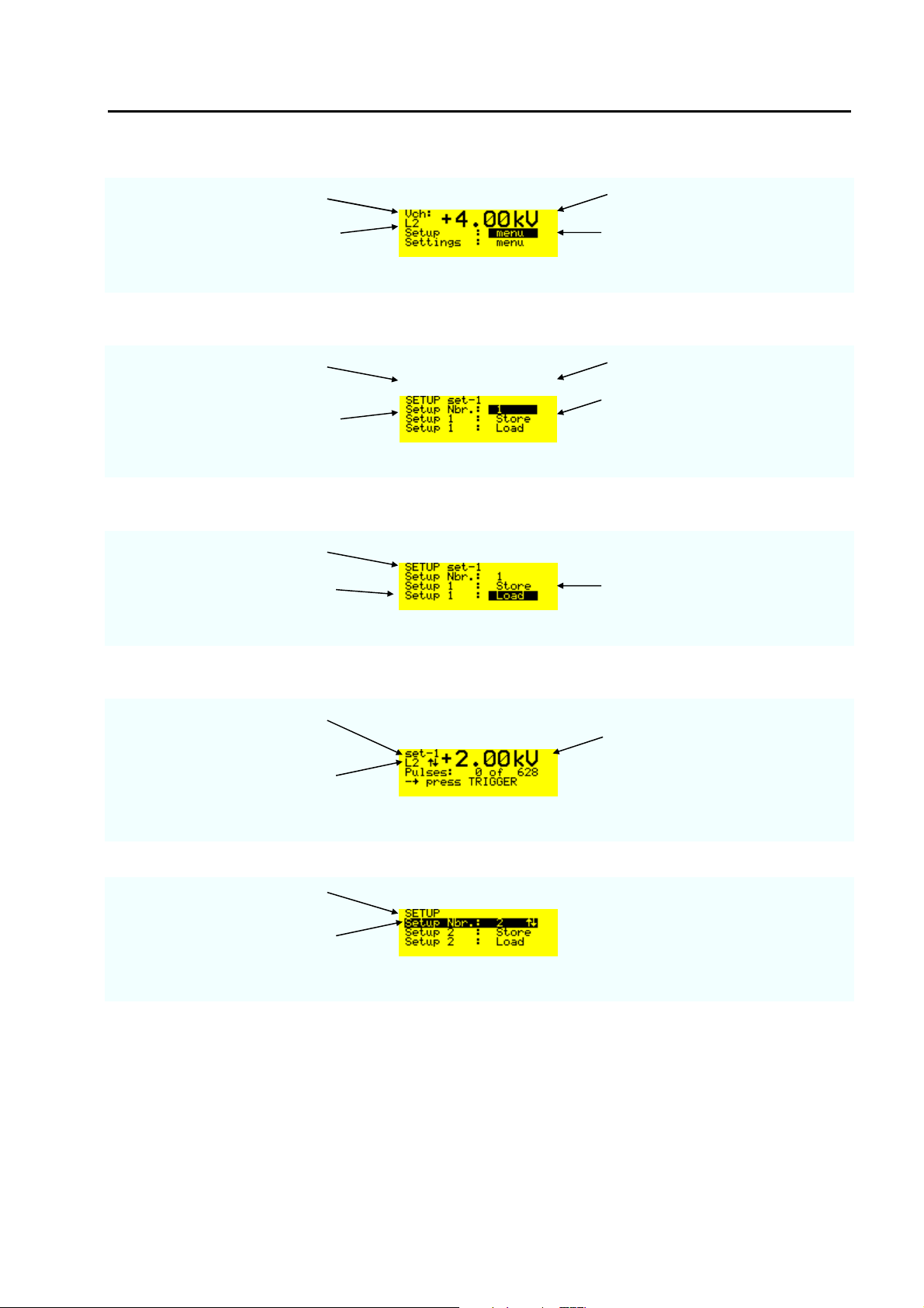
6.4.3 Menu „Setup“
charging voltage selected voltage level
voltage level selected L2 = 4 kV
Up to 9 customised parameter setup can be stored
When „ENTER „ has been pressed
SETUP indicates that in storage
selected voltage level
place 1 set-1 is stored
Setup Nbr. 1 to 9
All setted parameter of the
ESD3000 will be stored into the
set-1
With „Load“ and „ENTER“ button the set-1 can be activated.
Setup number
Setup Nbr.1 will loaded in to the
ESD3000 control
Up to 9 customised parameter setup can be stored
When the „ENTER“ button has been pressed twice.
Instead of Uch, set-1 indicats that
customer set-1 is loaded
selected voltage level to start the
ramp
L2 with the up and down arrow
indicates that a voltage ramp is
activated in the set-1
The set-up number 2 is empty
With up and down it can be
checked whether the storage
places are empty
31/66
Page 32
ESD3000-System
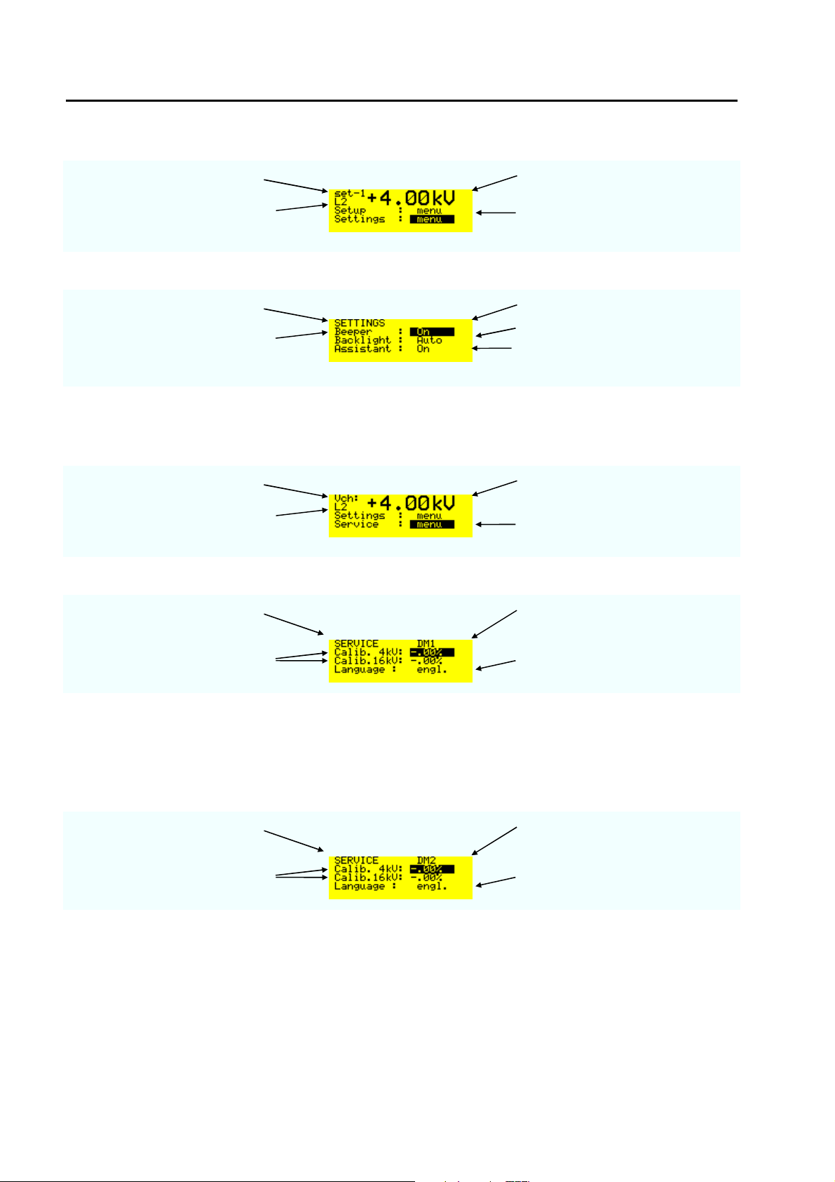
6.4.4 Menu „Settings“
charging voltage selected voltage level
voltage level selected L2 = 4 kV
When the black cursor is
positioned as showed and the
ENTER button is pressed, the
trigger change to „Auto“
menu page selected voltage level
Beeper „ON“ or „OFF“ with
“ENTER“ button
Backlight „Auto“, „OFF“ or „ON“
Assistant: „ON“ or „OFF“. The
message displays occur only when
the assistance is in the „ON“ mode
6.4.5 Menu „Service“
Last menu which can be found with the down arrows is the service menu
charging voltage selected voltage level
voltage level selected L2 = 4 kV
When the black cursor is
positioned as showed and the
ENTER button is pressed, the
display below will be showed
menu page ESD3000 equipped with
Discharge module DM1
calibration of the charging voltage
at 4 kV or 16 kV
For the time being only the English
version exists
Remark: With the voltage calibration divider ESD-VERI-V all customers can calibrate the voltages at 4 or 16
kV with an oscilloscope. The calibration factor include two values: the value from ESD3000 and the values
of the different discharge modules. As soon as the discharge module is interchanged the calibration factor
will be adapted to the new discharge module.
menu page ESD3000 equipped with
Discharge module DM2
calibration of the charging voltage
at 4 kV or 16 kV
For the time being only the English
version exists
Remark: This solution offers different advantages :
advantage 1: The accredited calibration Lab can calibrate the ESD3000 directly
advantage 2: Additional DM can extend the application of the ESD3000 system after the first sale. The
factor delivered with the DM must be set in the service menu.
32/66
Page 33
ESD3000-System
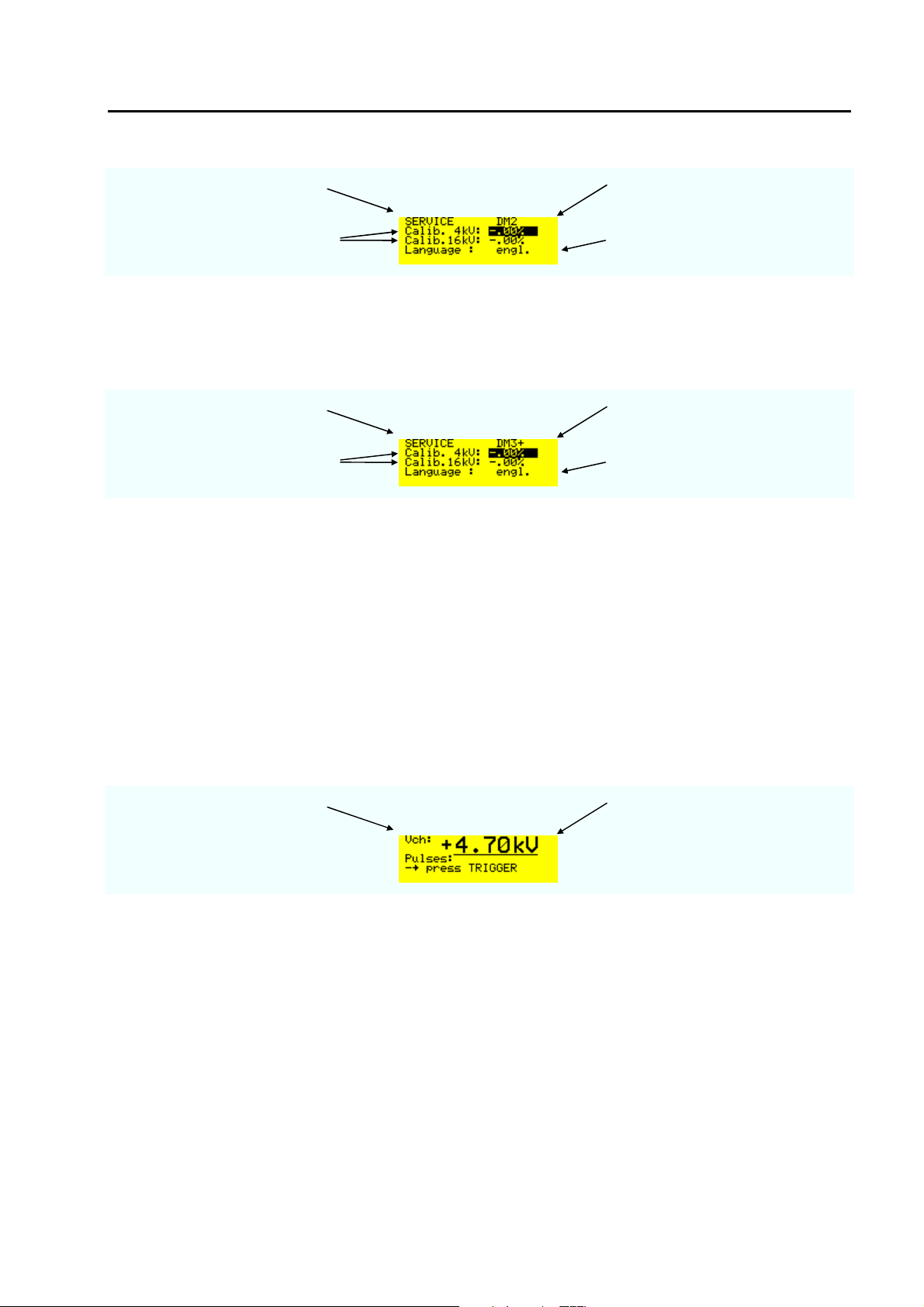
menu page ESD3000 equipped with
Discharge module DM2
calibration of the charging voltage
at 4 kV or 16 kV
For the time being only the English
version exists
Remark: When two discharge module exist for equal application e.g. two polarity for each discharge module
the factors are specified.
menu page ESD3000 equipped with
Discharge module DM3+
calibration of the charging voltage
at 4 kV or 16 kV
For the time being only the English
version exists
6.4.6 Reset of the ESD3000 to default values
When the ESD3000 is turned “OFF“ hold the +/- button and press the „RUN“ button. Relese the +/- button
when the message „reset to default“ is dispayed. If no message occur repete the reset.
6.5 Parameter changing during operation „RUN Mode“
6.5.1.1 Changing values during operation
In RUN-mode, several parameters can be continuously varied using the „up“ and „down “ buttons. This is
very helpful for exactly determining of the immunity level of the EUT. The manual change of the nominal
voltage will be noted in the report with a warning.
Charging voltage Increased voltage with „up“ during
For very fast investigation the polarity can also be changed during operation by pressing the +/button.
operation
33/66
Page 34
ESD3000-System
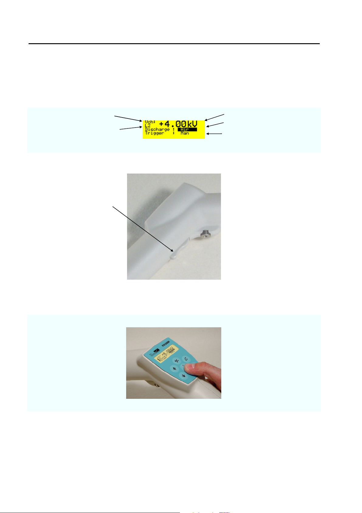
6.5.1.2 Point exploration with air discharge
The points on an EUT to which the discharges should be applied can be discovered by first doing an
exploratory test by running at a repetition rate of approximately 20 discharges per second or more.
With the ESD3000 and the ESD3000DM1 it can be arranged as following:
Select the desired discharge voltage in air discharge mode.
charging voltage polarity positive and voltage in kV
voltage level selected L2 = 4 kV
press ENTER button and the
display change contact to air
trigger mode manual
Press the „RUN“ button and hold the trigger button pressed on the main body
When the finger button is held
down the discharge tip is supplied
Hold this finger button
pressed
with d.c. The discharges will occur
with a repetition of approximately
20 Hz.
6.5.1.3 Putting out of operation
As showed above the „RUN“ button must be pressed until the message is shown „power down“.
34/66
Page 35
7 Maintenance and Servicing
7.1 Maintenance
No maintenance is necessary on the ESD3000.
7.2 Verification of the ESD3000 by the user
A full verification in accordance with the IEC standards can only be carried out with very expensive
measuring equipment. A simple verification is watching the spark at the finger or sharp tip to ground.
Ground cable must be connected. See warning advice on the ESD3000.
„ Make sure, the grounding cable is connected before you start using the ESD3000 high voltage“
7.3 Verification of the ESD3000 by EMC PARTNER AG
EMC PARTNER verify the ESD3000 in accordance with the verification chapter in the different standards.
ESD3000DM1 IEC 61000-4-2
ESD3000DM2 and DM3 ISO 10605
ESD3000DM4 MIL-STD-883
ESD3000DM5 RTCA/DO-160
ESD3000DM6 and DM7 IEC 61340-3-1 and IEC 61340-3-2
The ESD3000 and the discharge modules ESD3000DMx and ESD3000RM and networks have separate
test reports.
EMC PARTNER recommend a full verification of the ESD3000 once a year. A test report with all
oscillograms is included in the verification price. A full verification without a repair takes approximately 3
days.
Before a ESD3000 is delivered, all verifications are carried out in accordance with the basic documents.
All data are within the tolerable tolerances.
See verification report ESD3000 and DM or DN at the end of the Manual binder.
E-ESD3000-E-Manual.doc 35/66
Page 36
ESD3000-System
7.4 System Reset
A system reset can be made as follow:
1. Remove the batteries and wait about 5 to 10 seconds before inserting the batteries back.
2. With +/- hold, press button the power ON/OFF (RUN button).
The software will be reset to the default values.
7.5 Caution with calibration labels
It is strictly forbidden to use metallic labels for calibration information. No metallic labels are allowed on
neither on ESD3000 or modules and networks. Metallic labels could influence the current waveform or the
voltage withstand capability.
Only plastic foils are allowed.
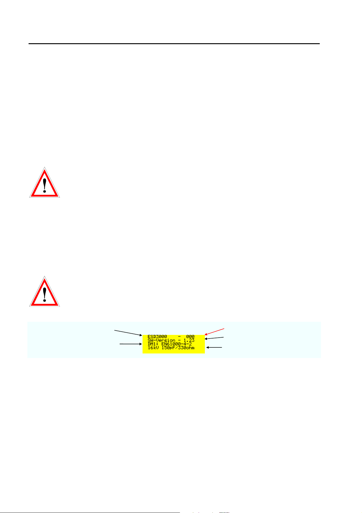
7.6 What must be done when the serial number is not indicated during the start up
If the serial number is not indicated in the display as showed below the stored information about
the DN are lost. The calibration data “calib” and serial number must be manually inputed. Only with the
correct % values the output current and voltages are correct.
test generator type
inserted discharge module DM
serial number
software version
main parameter of the DM
36/66
Page 37
8 What must be done following failed operation
• The ESD3000 has many of different messages to assist the operator to solve possible problems, give
information regarding incorrect operation of the ESD3000, or to correct an incorrect system
configuration.
8.1 Display messages
8.1.1 Examples of messages
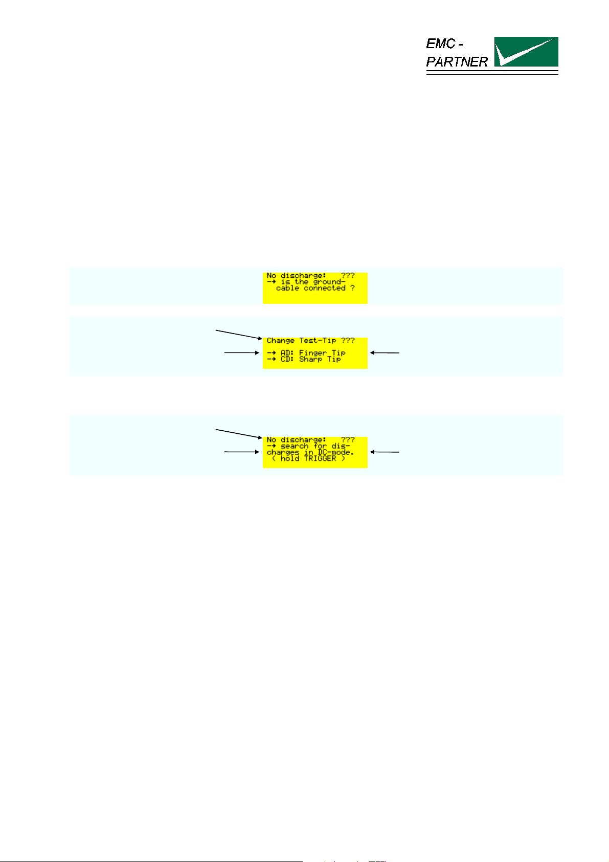
The following message will occur when after three releases no discharges was happen
Information display
AD = air discharge,
CD = contact discharge
check whether the correct tip is
put on the DM, AD = air discharge,
CD = contact discharge
Message display
advice for changing mode
8.2 Service; Repairs
The ESD3000 is a compact equipment and servicing or repairing the generator can only be carried out by
EMC PARTNER authorised service companies.
Do not continue to use the instrument should any mechanical damage occur. The instrument housing has
both an insulating and a screening function which can only be assured when the housing is intact. Return a
damaged generator to EMC PARTNER service centre immediately for repair.
8.3 Spare parts list
No spare parts are necessary for the ESD3000.
E-ESD3000-E-Manual.doc 37/66
Page 38

ESD3000-System
8.4 Service department of EMC PARTNER AG
EMC PARTNER AG
Baselstrasse 160
CH - 4242 Laufen
Switzerland
Tel. ++41 61 775 20 50
38/66
Page 39
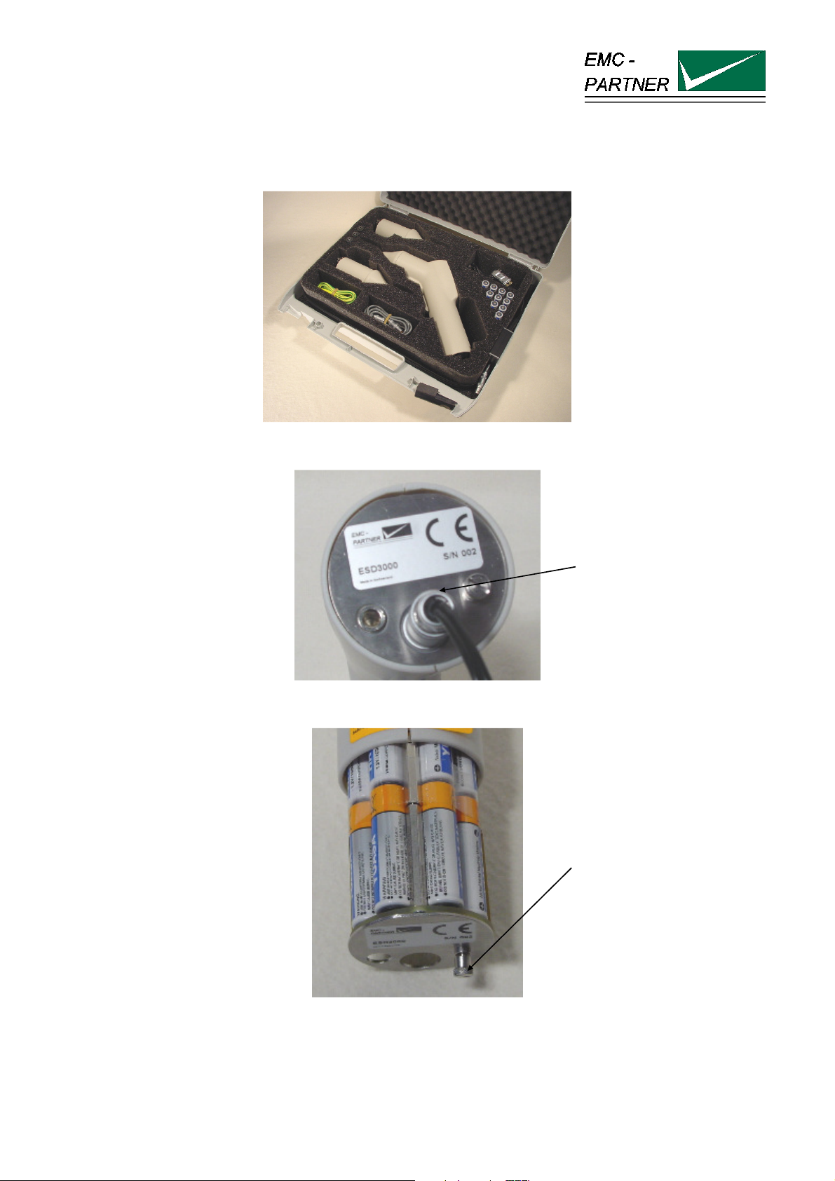
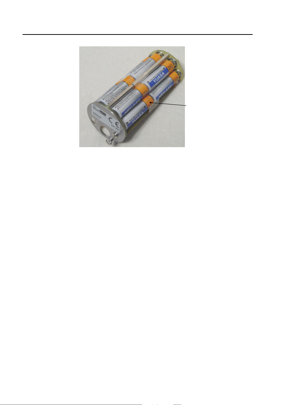
Connect the special Lemo
9 Charging the batteries or replacing batteries
The ESD3000 is a laboratory test equipment. Whenever the tester is not used, store it in the ESD3000 box.
The time the ESD3000 is not in use the batteries can be charge as follow.
The standard batteries can be changed as follow:
connector to the ESD3000 on
the bottom side. The power
supply cord must be
connected to a public outlet
with voltage 110 V up to 240
V 50/60 Hz
Unscrew the little screw on
the bottom of the ESD3000
and pull the battery back out
of the ESD3000
Charging time is approximately 5 hours (completely empty to completely full).
E-ESD3000-E-Manual.doc 39/66
Page 40
ESD3000-System
replace the batteries by pull it
out piece by piece
40/66
Page 41

10 Packaging and Transport
10.1 Packaging
If you transport the ESD3000, pack it in the original shipping box.
10.2 Transport
If you are transporting the ESD3000 to an EMC PARTNER field office for repair, attach a tag to the
equipment showing the instrument owner and address, the name of the person to contact about the
instrument, the instrument type and the serial number.
E-ESD3000-E-Manual.doc 41/66
Page 42

ESD3000- System
42/66
Page 43
11 Recycling / Disposal
11.1 RoHS directive 2002/95/EG
The ESD3000 complies with the directive 2002/95/EG (RoHS - Restriction of certain Hazardous
Substances). From July 2006 onwards.
From December 2005, all EMC Partner products either hand soldered or by machine are produced using
lead-free solder.
11.2 WEEE directive 2002/96/EG
The EMC Partner ESD3000, is exempted from the directive 2002/96/EG (WEEE) under category 9.
The product should be recycled through a professional organisation with appropriate experience for the
disposal and recycling of electronic products. EMC Partner are also available to help with questions relating
to the recycling of this product.
11.3 Information for dismantling
Remove always power cord fist.
There is no special danger involved in dismantling the ESD3000.
11.4 Parts which can be recycled
The ESD3000 contains parts made from steel, aluminium, PVC, two-component sealing compound. The
impulse capacitors are filled with non-poisonous mineral oil. The various parts can be separated and
recycled.
11.5 Parts which can not be recycled
All parts in the ESD3000 can be recycled.
E-ESD3000-E-Manual.doc 43/66
Page 44

ESD3000- System
44/66
Page 45
12 Modules and accessories
12.1 ESD3000 with DM discharge modules
Pos. Product No. Type Short Description
103606 ESD3000DM1 Discharge module IEC 61000-4-2, 150pF, 330 Ohm, AD up to
16kV, CD up to 10kV.
Incl.
. 1 rounded tip for AD
. 1 sharp tip for CD
103607 ESD3000DM2 Discharge module ISO TR10605, 330pF, 2000 Ohm, AD up to
16kV, CD up to 10kV (inside vehicle).
Incl.
. 1 rounded tip for AD
. 1 sharp tip for CD
103608 ESD3000DM4 Discharge module MIL 883 and GR-78-CORE 100pF, 1500
Ohm, CD up to 10kV, AD up to 16kV.
Incl.
. 1 sharp tip for CD
. 1 rounded tip for AD
. 1x 0.75m cable green-yellow
. 1 ESD-MC plug blue
103609 ESD3000DM5 Discharge module RTCA/DO160-D, 150pF, 330 Ohm, AD up
to 30kV consisting of ESD3000DM5+ and ESD3000DM5-.
Incl.
. 2 rounded tips for AD
103610 ESD3000DM6 Discharge Module IEC 61340-3-1, 100pF, 1500 Ohm, CD up
to 8kV.
Incl.
. 1 sharp tip for CD
103611 ESD3000DM7 Discharge Module IEC 61340-3-1, 200pF, 0 Ohm, CD up to
3kV.
Incl.
. 1 sharp tip for CD
103612 ESD3000DM8 Discharge Module in accordance with IEC 60571 and EN
50155 for Railway Testing
E-ESD3000-E-Manual.doc 45/66
Page 46

ESD3000- System
Pos. Product No. Type Short Description
103625 ESD3000RM32 Relay module with high voltage and polarity switch. Circuit for
generating the first current peak. Can be used for CD up to
30kV and AD up to 30kV. Minimum one DN must be added.
Incl.
. 1 rounded tip for AD
. 1 sharp tip for CD
. 1 electrode 30mm
. 1 permanent magnet.
103615 ESD3000DN1 Discharge Network according to IEC 61000-4-2 with capacitor
150pF and resistor 330 Ohm. AD from 1kV up to 30kV and CD
from 1kV up to 30kV.
103616 ESD3000DN2 Discharge Network according to ISO TR10605 with capacitor
330pF and resistor 2000 Ohm. AD from 1kV up to 30kV and
CD from 1kV up to 30kV.
103617 ESD3000DN3 Discharge Network according to ISO TR10605 with capacitor
150pF and resistor 2000 Ohm. AD from 1kV up to 30kV and
CD from 1kV up to 30kV.
103618 ESD3000DN4
For explosive device testing MIL-STD-1512 or VG95378 with
capacitor 500pF and resistor 5000 Ohm. AD from 1kV up to
30kV and CD from 1kV up to 30 kV.
Consisting of 1 discharge network. ESD3000DM-EXT and
safety switch must be ordered separately.
103619 ESD3000DN5
Discharge network for military testing according to
MIL-STD-331, MIL-DTL-23659D or STANAG 4239. 500pF,
500 Ohm.
AD and CD 2kV up to 30kV. Requires ESD3000RM32.
ESD3000DM-EXT & safety switch can be ordered separately
104126 ESD3000DN6
Discharge network for automotive testing according to ISO
TR 10605. VW TL 824-66 and Daimler Chrysler DC 10614.
330pF, 330 Ohm. AD and CD 2kV up to 30kV. Requires
ESD3000RM32.
46/66
Page 47

ESD3000-System
Pos. Product No. Type Short Description
103627 ESD-
OPTOLINK
Optical link to control ESD3000 from PC. Must be ordered together
with TEMA. Optolink length 10 m with special LEMO plug and
RS232 9 pin connector. Incl. 1x ESD-TRA-CABLE
103630 ESD-
TARGET2
2 Ohm Target with SMA connector, upper limit >4GHz. For ESD
calibration verification and comparison. Calibrated target attenuator
cable chain.
Incl.
- 1x cable 50 Ohm
103629 ESD-VERI-V Charging voltage (up to 25kV) measurement divider 20Gohm, ratio
determined by the 1Mohm input of the oscilloscope. Ratio approx.
1:20'000. Incl MC banana plugged cable green/yellow (1x 0.80m).
103485 ESD-VCP50 Vertical coupling plate 0.5 x 0.5m with 2m cable and 2 x 470kOhm
resistors.
103637 ESD-STAND
Ed2
Non metallic stand for ESD MOUSE, ESD2000, ESD3000
ESD3000DM-EXT, in accordance with IEC 61000-4-2 Ed.2
103634 CNH12 Accessory to ESD3000 with RM32 and DN1 to simulate rapidly
changing H-field as generated at real ESD discharge.
103628 ESD3000DM-
EXT
Accessory to ESD3000DM's to separate the control and the
discharge module for special applications like airbag or explosive
device testing. With the ESD3000DM-EXT the control can be
separated maximum 1m.
103626 ESD3000
SAFETYSWITCH
Safety switch to short circuit the ESD3000 output, when testing
explosive devices. Must be used together with ESD3000DN4 and
ESD3000RM32.
47/66
Page 48
ESD3000- System
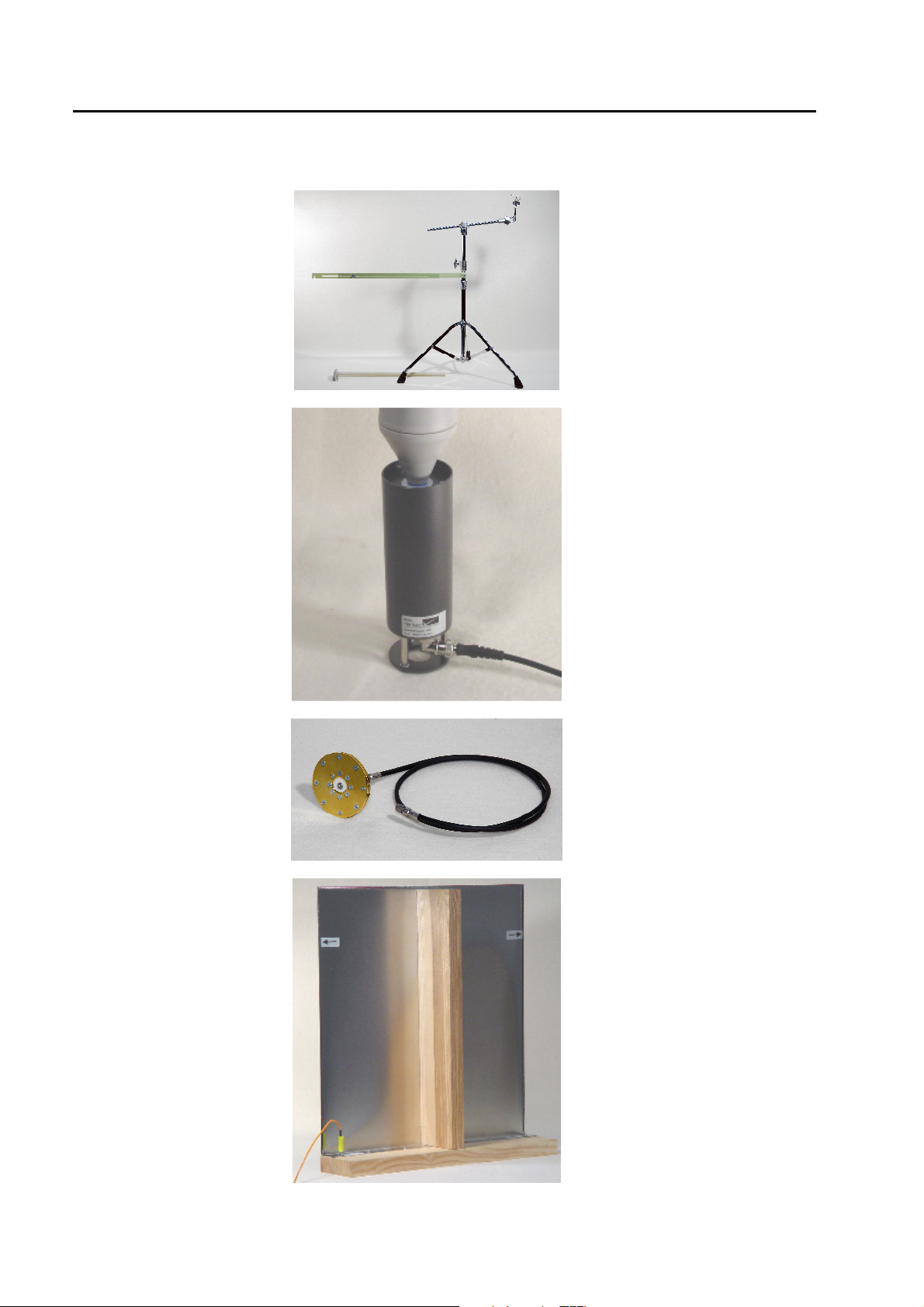
12.2 Pictures of the accessories
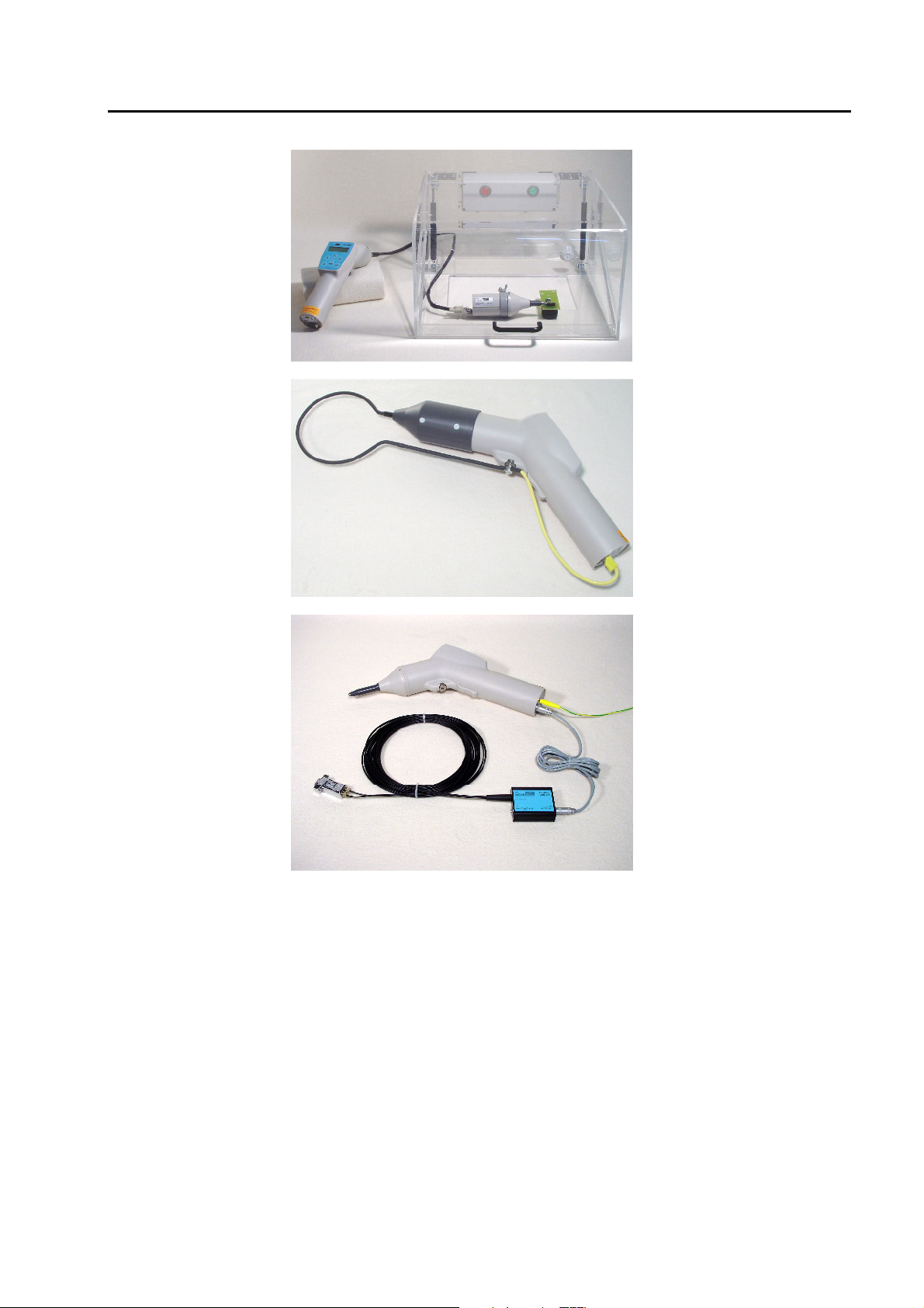
ESD-STAND Ed2:
ESD-VERI-V:
Height adjustable from 0.4 m
up to 1.75 m
Application:
long term tests in contact and
air discharge mode
20 G divider for high voltage
measurement on the
ESD3000 up to 25 kV.
Ratio is determined by 1 M
Ohm input of the
oscilloscope.
Ration approximate 20’000
ESD-TARGET2:
VCP50
2 Ohm Target with SMA
connector, upper limit >4GHz
Vertical coupling plate.
Mechanical dimension: 0.5 x
0.5 m
Application indirect ESD
discharge with contact tip.
48/66
Page 49
ESD3000-System
ESD3000DM-EXT
CNH12
Testing of EUTs that could
spontaneously explode or
rapidly change state, such as
airbags or munitions fuses
Accessory to ESD3000 with
RM32 and DN1 to simulate
rapidly changing H-field as
generated at real ESD
discharge.
ESD-OPTOLINK
.
Accessory to ESD3000 to
remote control the ESD3000
without any galvanic
connection
49/66
Page 50

ESD3000- System
50/66
Page 51
13 E3Loader and Serial Communication
13.1 Remote control with „E3Loader“
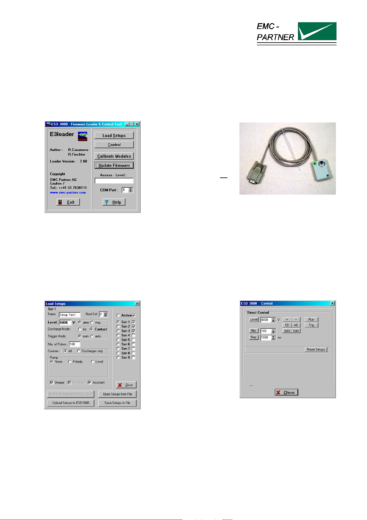
The E3Loader program, delivered with ESD3000, is a basic software package primarily used for updating
firmware and, with the optional ESD-VERI-V, adjusting the HV-DC level. E3Loader can also be used as a
simple remote control tool.
The Download-Module
(picture right) connects
ESD3000 to a 9-pin serial
port on the PC.
This is an easy way to
upload new settings or
firmware but as there is no
galvanic insulation highvoltage testing is not
possible.
For remote controlled testing,
an optional optical RS232
interface is required.
The serial port uses just the data lines TxD and RxD for information transfer (9600Baud, 8 N 1).
13.2 Controlling ESD3000
Click ‘Load Setup’ to enter
the parameter input menu
(picture left). Parameters
can be changed and saved
in one of 9 memory
locations on the computer
hard disk. These setup files
can be transferred to the
ESD3000 using the
download module.
Click ‘Control’ to enter the
real-time test menu (picture
right). Parameter values
can be changed, even when
ESD3000 is operating
(optical interface required).
E-ESD3000-E-Manual.doc 51/66
Page 52
ESD3000- System
13.3 Module Calibration
13.4 Firmware Upload
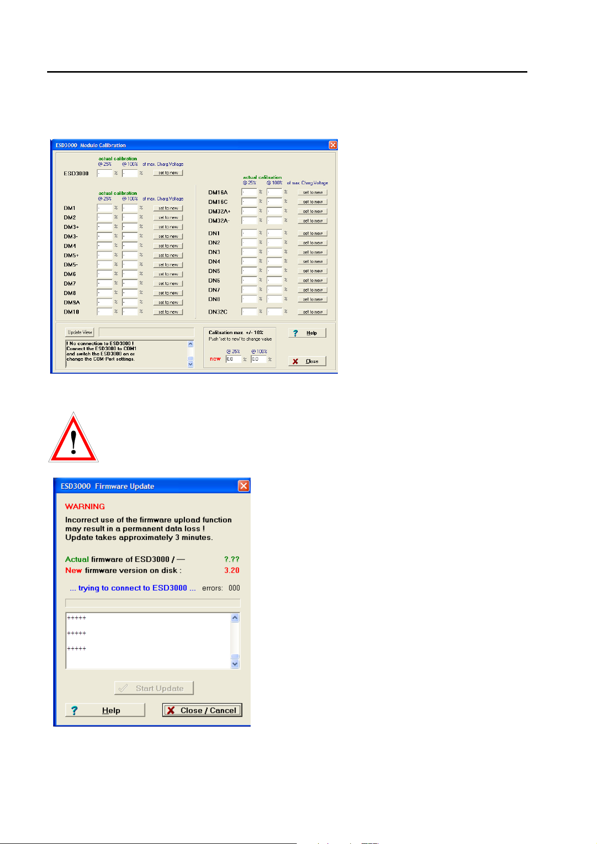
Together with an optional highimpedance high-voltage divider
(ESD-VERI-V), a recalibration and
adjustment of the dischargemodules (DMx) can be performed
and stored in the ESD3000 memory.
ATTENTION
Incorrect use of the firmware upload may result in permanent data loss ! See Warning
windows before the upload starts.
How to update the ESD3000 Firmware:
1. Using The download module, connect ESD3000 to
the serial port of a computer
2. Switch on ESD3000. Make sure system power is
maintained during the upload process (Batteries
fully charged before start of update ). This takes
approximately 10 minutes.
3. The window indicates the firmware version on the
ESD3000
and the version on the hard disk.
4. If communication with the upload monitor inside the
ESD3000 is established (message...connected to
ESD3000...), click on ‘Start Update’ and wait until
the message ‘...Upload successful...’ appears.
5. Restart the ESD3000 and check if the new version
is shown in the display.
52/66
Page 53
14 ESD3000 Control with Test-Manager (Tema)
14.1 Remote Control from PC
Direct control of the ESD3000 with a PC requires the following items:
− ESD-OPTOLINK (RS232-interface with 10m optical wire)
− ESD-TRA-CABLE (cable with LEMO plugs to connect interface and ESD3000)
− TEMA (‘Test-Manager’ software)
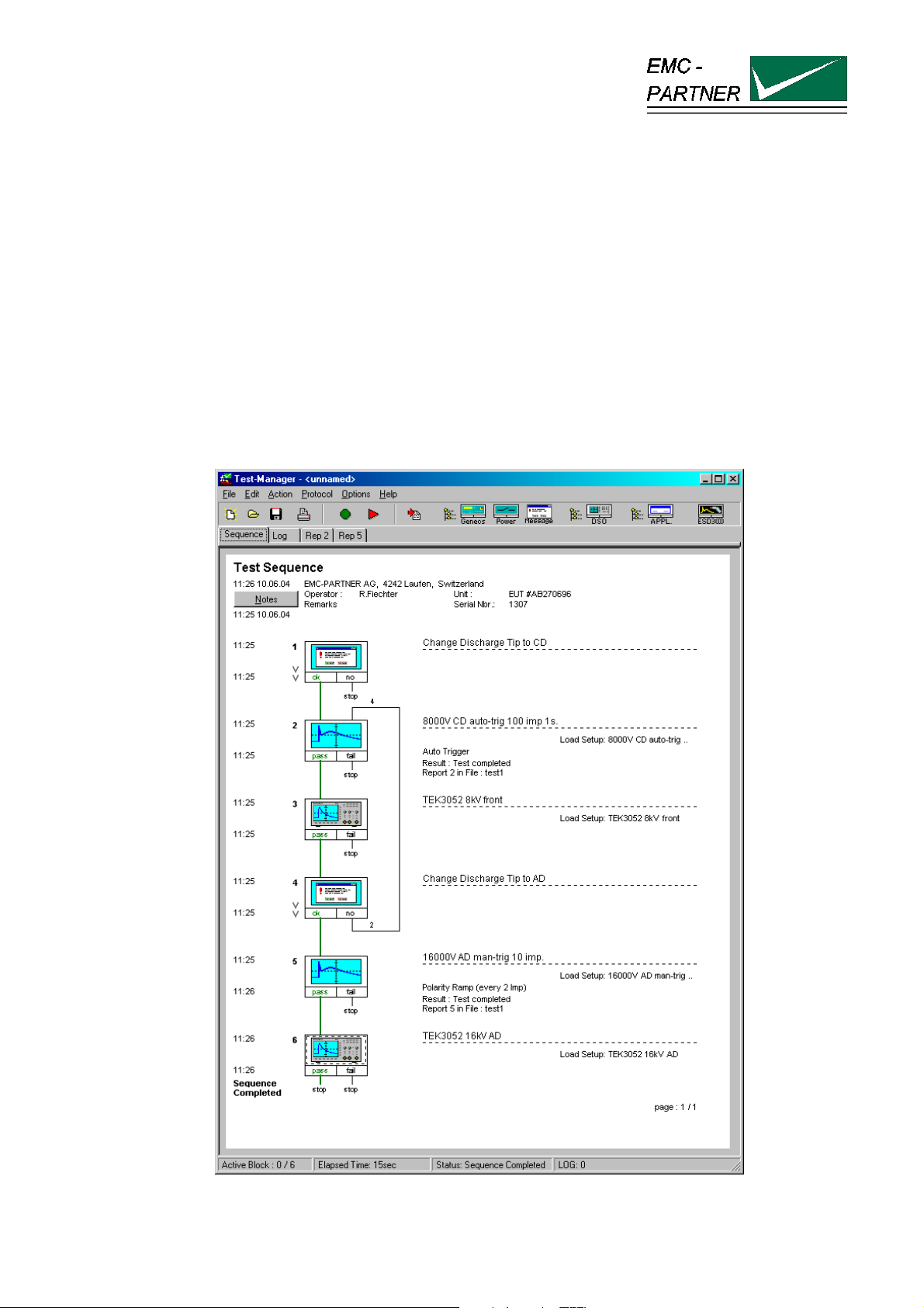
Test-Manager software is available for all EMC Partner generators and enables complex test sequences to
be programmed using standard windows methods. Test reports can be generated which include results
from different generator sources and pictures from a DSO (Digital Storage Oscilloscopes).
ESD3000 can be connected directly to a PC and benefits from all these features.
When TEMA software is started, the following window appears:
E-ESD3000-E-Manual.doc 53/66
Page 54

ESD3000- System
54/66
Page 55
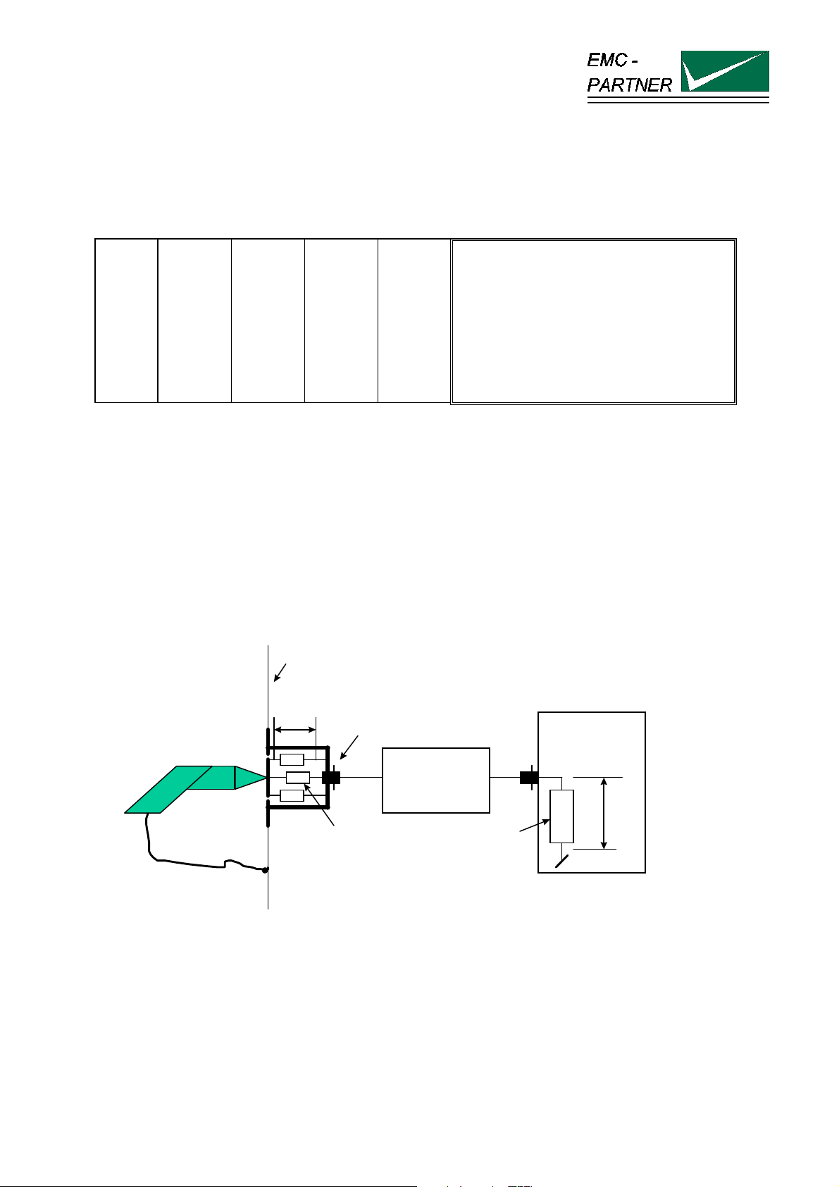
15 Appendix and Corrections
15.1 Appendix
15.1.1 Definition of the ESD Waveform
Level
1
2
3
4
It is only possible to check the impulse current by using very expensive pieces of measuring equipment. The
price of such an instrument today lies at approx. 50 k$. In addition, persons who carry out such tests must
have some experience with high voltage and high frequency test work, so that they can interpret the
measured values. The calibration and verification of the generators must be carried out by the manufacturer
or the official calibration authorities.
Test
voltage
kV+-30%
2
4
6
8
Peak
current
A+-30%
7,5
15
22,5
30
Amplitude
at
30ns
A+-30%
4
8
12
16
Amplitude
at
60 ns
A+-30%
2
4
6
8
Current peak
wall cage
u1
ESD-Mouse
50 Ohm Termination
2 Ohm Target
Attenuator
e.g. 20 dB
Oscillograph
u2
50 Ohm
The ESD-current produces on 2 Ohm Shunt a voltage trop u1. The 2 Ohm target is terminated with 50 Ohm
to avoid reflection. With the 20 dB attenuator the 60V trop on the 2 Ohm will be reduced to the allowed input
voltage of the oscilloscope. The memory oscilloscope must have a minimum bandwidth of 1 GHz. For all
four levels (2,4,6,8 kV) the current wave-form must be within the tolerances as specified in the IEC standard
61000-4-2.
The calibration of the ESD generator should be made at manufacturer side or at an accredited test house.
E-ESD3000-E-Manual.doc 55/66
Page 56

ESD3000- System
15.2 Correction
15.2.1 Declaration of conformity to the EMC directive 89/336/EEC
see appendix at the end of this documents.
15.2.2 Declaration of conformity to the LV directive 93/68/EEC
see appendix at the end of this documents.
15.2.3 Declaration of conformity to the Basic Standards
see appendix at the end of this documents.
56/66
Page 57
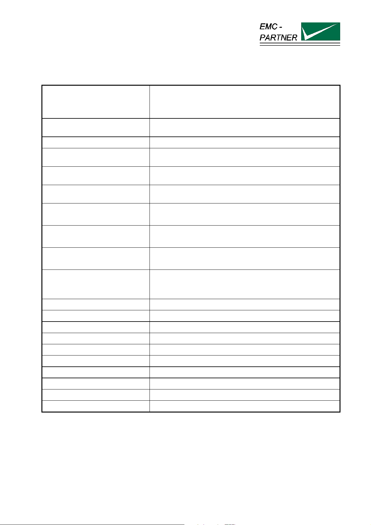
16 Glossary
Wherever possible, definitions in accordance with IEC 50 (IEV 161) are used.
EUT
EST
EMV = EMC = CEM Electro Magnetic Compatibility German:Elektromagnetische
Hybrid pulse Voltage at no load 1.2 / 50 µs and current at short circuit 8 / 20µs.
CWG Definition in IEC 1000-4-5 used for Surge Tester Combination
Coupling network Electric circuit for transferring energy with low losses from one
Decoupling network Electric circuit to prevent transmitting energy from one circuit into
CDN coupling decoupling network
(single or three phase unit)
EFT Electric Fast Transient
ESD Electric Static Discharge
Equipment under Test
French abbreviation of EUT
Verträglichkeit French: compatibilité elctromagnetique
wave generator.
circuit into another circuit.
another circuit.
Consist of a coupling and a de-coupling network.
(switched inductance)
SURGE Transients with high energy content with relatively low frequency
content
as produced by lightning and switching of power lines.
DIP Short voltage interruption or short voltage drop
IEC International standardisation organisation for electronic technology
VARIAC Voltage variable transformer
SPIKE One pulse of the burst
CRO oscilloscope
HV High Voltage
rms. root mean square; effective value
E-ESD3000-E-Manual.doc 57/66
Page 58
ESD3000- System
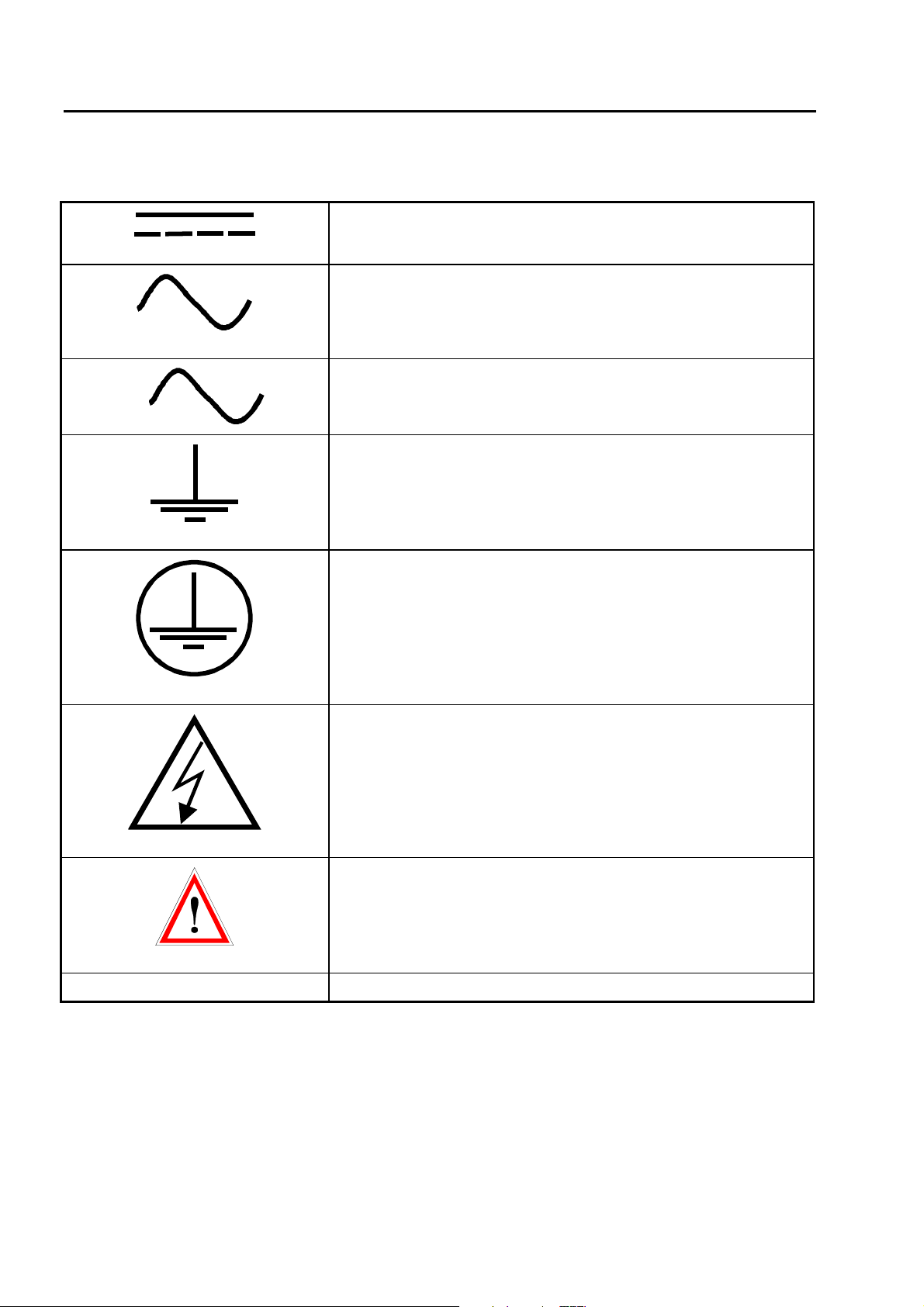
Used symbols:
3
Direct current
Alternating current
Three phase alternating current
Earth (ground) terminal
Protective conductor terminal IEC 417, No. 5019
Caution, risk of electric shock
ISO 3864, No. B.3.6
Caution (refer to accompanying documents)
ISO 3864, No. B.3.1
58/66
Page 59

17 Index
Technical data 11
EUT 57
A
Attention refer to manual 16, 21
C
charging the batteries 39
Climatic Condition 15
Control panel
Control part 19
Control Panel
Front of the ESD3000 19
Coupling network 57
CWG 57
D
Decoupling network 57
delivered standard set-ups 25
E
Electromagnetic Compatibility 16
EMC 57
Error caused by incorrect inputs 37
Error messages 37
ESD
characteristics 7
Modules and Accessories 45
source 7
ESD Run Mode 33
ESD3000DM3
Technical data 9
ESD3000DM4
Technical data 9, 12
ESD3000DM5
Technical data 10
ESD3000DM6
Technical data 10
ESD3000DM7
Technical data 10
ESD3000DN1
Technical data 11
ESD3000DN2
Technical data 11
ESD3000DN3
M
Maintenance 35
Mechanical dimension 12
O
Operational Conditions 15
Options 45
P
Packaging and shipment 41
personal safety 15
Power line voltage, power consumption 12
R
Recycling/Disposal 43
S
Safety
Precautionary measure 16
Safety
Standards 15
Service, Repair 37
SURGE 57
Symbols 58
T
Test 57
test set-up for table top equipment 22
V
Verification of EMC PARTNER 35
E-ESD3000-E-Manual.doc 59/66
Page 60

ESD3000- System
60/66
Page 61
Declaration of Conformity to Standards
The EMC Tester
complies with the following standards:
ESD3000DM1 IEC 61000-4-2
ESD3000DM2 and DM3 ISO 10605
ESD3000DM4 MIL-STD-883
ESD3000DM5 RTCA/DO-160
ESD3000DM6 and DM7 IEC 61340-3-1 and IEC 61340-3-2
Type: ESD3000 with DMx or DNx
Laufen, 02. February 2004
EMC PARTNER AG
M. Lutz
Managing Director
Appendix to 14.2.3 Conformity declaration with basic standards
EMC PARTNER AG
R. Henz
Manager Quality
E-ESD3000-E-Manual.doc 61/66
Page 62

ESD3000- System
62/66
Page 63
Manufacturer Declaration Of Conformity EMC
Directive 89/336/EWG with table VII 2004/108/EG
The EMC Tester
is designed and manufactured complying with the following harmonised standards:
has been tested in accordance with the following standards:
harmonised:
international
Fulfilling the directions of the EMC - Directive 89/336/EWG and with table VII 2004/108/EG
EMC PARTNER authorised representative established within the EC Community
Laufen: 04. August 2009
EMC PARTNER AG
Type: ESD3000; S/N > 10
EN 61000-6-3: 2007
EN 61326: 2006
IEC 61000-6-3
IEC 61326-1
H+H High Voltage
Technology GmbH
Im kurzen Busch 15
DE - 58640 Iserlohn
EMC PARTNER AG
M. Lutz
Managing Director
Appendix to 14.2.2 K Conformity declaration with the EMC directive
E-ESD3000-E-Manual.doc 63/66
R. Henz
Manager Quality Department
Page 64

ESD3000- System
64/66
Page 65

Manufacturer Declaration Of Conformity LV
Directive 73/23/EWG; with table VI 2006/95/EG
The EMC Tester
has been tested in accordance with the following standards:
Harmonised:
international
in accordance with the regulation of LV - directive of the members states 73/23/EWG and with table VI
2006/95/EG
EMC PARTNER authorised representative established within the EC Community
Laufen, 05.August 2009
EMC PARTNER AG
Type: ESD3000, S/N > 10
EN 61010-1: 2001
IEC 61010-1
H+H High Voltage
Technology GmbH
Im kurzen Busch 15
DE - 58640 Iserlohn
EMC PARTNER AG
M. Lutz
Managing Director
Appendix to 14.2.2 Conformity declaration with Low Voltage Directive 93/68/EEC and with table VI
2006/95/EG
E-ESD3000-E-Manual.doc 65/66
R. Henz
Manager Quality Department
Page 66

ESD3000- System
66/66
 Loading...