

Emco-test DuraJet G5, DuraJet 10 G5 Instruction Manual


Hardness Tester
Introduction
DuraJet 10 G5
1-1
Instruction manual
Original instruction manual
DuraJet G5
A2015-05 EN
EMCO-TEST Prüfmaschinen GmbH
Kellau 174 A-5431 Kuchl
Tel: +43 6244 20438 – Fax: +43 6244 20438-8
office@emcotest.com – www.emcotest.com

Hardness Tester
Introduction
DuraJet 10 G5
1-2
Contents
1 Introduction 1-1
1.1 Preface 1-1
1.2 Safety notes 1-1
1.3 Manufacturer's notes 1-3
1.4 Icons and Typographic Conventions 1-5
1.5 Technical Data 1-7
2 Startup 2-1
2.1 Transporting the Machine 2-1
2.2 Scope of Supply 2-2
2.3 Weight and Dimensions 2-4
2.4 Installing the Machine 2-4
2.5 Initial Startup 2-9
3 Design and Functions 3-1
3.1 Design, Methods and Data Interfaces 3-1
3.2 Control Unit 3-2
4 Basic Operation 4-1
4.1 Switching the Machine On and Off 4-1
4.2 Touch Screen 4-1
4.3 Virtual Keyboard 4-1
4.4 Symbols and Buttons 4-3
4.5 Test Sequence 4-7
4.6 Testing Without the Nose Cone 4-12
5 Advanced Options 5-1
5.1 Opening the setting menu 5-1
5.2 General settings 5-2
5.3 User boxes 5-5
5.4 Export 5-6
5.5 Report 5-6
5.6 Network 5-9
5.7 Printer 5-9
5.8 Checking Load Calibration 5-9
5.9 Calibrating the Depth Gauge System 5-10
5.10 Documenting and Evaluating Results 5-11
5.10.1 Displaying, Printing and Exporting Results 5-11
5.10.2 Deleting Results 5-12
6 Cleaning and Maintenance 6-1
7 Startup and Retooling with Optional Accessories 7-1
7.1 USB 7-1

Hardness Tester
Introduction
DuraJet 10 G5
1-3
7.2 External machine control via hardware interface 7-2
7.3 Foot button 7-6
7.4 Replacing the Fuses 7-6
7.5 Replacing the Test Anvil 7-8
7.6 Test Methods and Indenters 7-11
8 Messages and Problems 8-1

Hardness Tester
Introduction
DuraJet 10 G5
1-1
1 Introduction
1.1 Preface
Our hardness testing machines represent state-of-the-art technology and comply with
current norms and standards. Both the hardware and software in our machines can be
upgraded on an ongoing basis. As a result, you can ensure that the technology in your
machine is always up-to-date.
The machines are equipped with a measuring system and electronic power control.
They are also distinguished by their ergonomic design and user-friendly software, which
complies with DIN standards.
Take your time to read this instruction manual thoroughly. You will be amazed by the
many application options available.
1.2 Safety notes
Familiarity with the applicable safety regulations is a prerequisite for safe, error-free
operation of this machine.
Refer to the instructions in this manual, and, in particular, to the safety instructions,
when operating the machine. It is also essential that you observe all rules and
regulations for accident prevention that apply in the location where the machine is
operated.
The design of this machine and its equipment is state-of-the-art and complies with
recognized safety regulations. Nevertheless, risk of injury or death to the user or third
parties may arise in certain cases, and the machine or other property may be damaged.
Icons are used to highlight these risks in the relevant chapters.
Read all operating instructions before you start the machine.
Keep the operating instructions in the vicinity of the machine. Order a new copy if you
lose it.
To avoid personal injury while moving the machine, never try to move it unassisted. The
machine's weight is approximately 110 kg.
Remove all transportation safety devices before starting the machine.
▪ Position the machine on a secure and stable working surface.
▪ Ensure that its working height is in accordance with ergonomic principles and will
not result in unnecessary physical strain.
▪ Ensure that there is sufficient space available to access the machine and that an
adequate escape route is kept clear to provide for unforeseen incidents.
▪ Ensure that the work station has adequate lighting.
▪ The hardness testing machine must be protected against shocks and vibrations that
can influence the test result.
Please bear in mind that the machine must not be used in explosive environments.
Ensure that workwear is close-fitting and cannot become entangled in the machine's
moving parts. Make sure you use your personal protective equipment.
The machine must be connected to a grounded electrical outlet (a protective conductor
contact is required).
Safety regulations
Operating instructions
Moving the machine
Transportation safety
devices
Installation
Fire and explosion
protection
Workwear and
protective equipment
Electrical power supply

Hardness Tester
Introduction
DuraJet 10 G5
1-2
Do not work with the machine for too long or when you are unable to concentrate
properly.
The machine must not come into contact with water. Protect the machine from
splashing.
Before each startup, ensure that the machine is in a flawless condition and that none of
the safety features have been removed and are all functional. Any damaged cables
must be replaced immediately by authorized personnel.
Ensure that the machine is only operated by authorized and properly trained persons.
Ensure that the machine cannot be started or operated by unauthorized persons.
Ensure that the machine is only operated by one person at all times.
Do not make any unauthorized changes to the machine's safety features. Bridging of
control features and any interference with the electrical/electronic components of the
machine are not permitted and will nullify the warranty in all cases.
In case of emergency, shut down the machine immediately with the EMERGENCY-OFF
button.
Before testing, check that the testing tools are securely clamped.
Do NOT attempt to touch the internal parts of the machine while it is operating.
Use appropriate fixings to secure any workpieces that do not stay in place without
support.
Never hold workpieces in place by hand!
Wear protective gloves when handling heavy or sharp workpieces or removing chips.
Use the main switch to turn the machine off before resetting.
Never leave the machine unsupervised while it is operating. Always switch the machine
off before leaving the work station.
Keep your work station clean and tidy. A cluttered work station increases the risk of
injury.
Use the main switch to turn the machine off. Remove the power plug to disconnect the
machine from the power supply before you carry out any maintenance or readjustments.
Any work on the machine's electrical parts unit should only be carried out by skilled
electricians or service technicians.
Comply with the stipulated inspection and maintenance intervals (see standards EN ISO
6507, EN ISO 6505, EN ISO 6508, EN ISO 4545, EN ISO 2039).
Contact your supplier in the event of collision or damage. Always specify the unit
number and software version of your machine in cases of complaint or damage or when
making inquiries or ordering replacement parts.
Work time
Protection from
splashing
Startup
Operation by
authorized personnel
Single-person machine
Unauthorized changes
EMERGENCY-OFF
Securing workpieces
Resetting the machine
Supervision
Work station
Maintenance
Claims

Hardness Tester
Introduction
DuraJet 10 G5
1-3
1.3 Manufacturer's notes
The rating plate sits at the right-hand side on the base. It shows the information that is
required to identify the machine.
1
Manufacturer information
2
Type name
3
Serial number
4
Mains voltage
5
Nominal motor voltage
6
External fuse
7
Number of the circuit diagram
8
Disposal information
9
CE sign
10
Year of manufacture
Address
EMCOTEST Prüfmaschinen GmbH
Kellau 174
5431 Kuchl
Austria
Phone
+43 6244 20438
Fax
+43 6244 20438-8
E-mail
office@emcotest.com
Internet
www.emcotest.com
The machine is intended to be used to test hardness in accordance with the following
methods:
Metals, plastic material and carbon material
▪ Rockwell EN ISO 6508, ASTM E18
▪ Plastics EN ISO 2039-1
▪ Brinell and Vickers, depth hardness only, not standardized
▪ Testing carbon material DIN 51917
Conversion standards: DIN EN 50150, EN ISO 18265, ASTM E140-05.
Testing other material is not permitted or, in exceptional cases, only after agreement
with your contact person. Never use poisonous or harmful materials. Intended use also
includes observing the specified operating and maintenance instructions.
The machine must be installed in a clean location. It is particularly important that this
location is free of metal chips, dust, smoke and other contaminants. If the ambient air at
Rating plate
Manufacturer
information
Intended use
Hardness Tester
Introduction
DuraJet 10 G5
1-4
the installation location is contaminated, the machine must be operated in a separate
closed test cell.
The machine may only be operated by persons who have been properly trained in the
operation, maintenance and repair of the machine, and are aware of the risks involved.
All accident prevention and safety instructions for operating the machine must be
observed. The manufacturer does not accept any liability in cases where the machine is
used for purposes other than those for which it is intended. In these cases, liability is
transferred to the user.
The machine is adjusted for the ambient temperature specified in the technical data.
The machine must not be used to test workpieces with low mechanical stability, which
may become distorted or may break when clamped.
Workpieces that are stable but do not have the required structural integrity may only be
clamped if they are secured using appropriate fixings.
The machine should not be used for workpieces which are toxic or harmful to health.
The CE mark and the EC conformity declaration certify that the machine and this
manual comply with the stipulations of the directives that apply to the product.
The WEEE symbol on your unit indicates that it is a WEEE-relevant machine
containing electrical/electronic components and must not be disposed of as general
waste. For more information about recycling this product, contact your relevant local
authority.
The warranty period for new machines is 24 months from the date of delivery by the
manufacturer with unlimited operating hours.
If a defect is detected, inform your sales partner or nearest service center of the
manufacturer immediately, providing a detailed description of the defect in written form,
over the phone or in person.
Defects that are properly reported and are covered by the manufacturer's warranty will
be corrected free of charge either by repair or replacement delivery. If requested,
defective parts are to be returned to the manufacturer at the customer's expense and
risk.
The manufacturer's warranty does not apply to defects that are caused by one or more
of the following:
▪ failure to fully comply with the operating instructions, safety and licensing
regulations or other instructions relating to the delivery, installation, startup or use of
the machine
▪ incorrect assembly or startup of the machine
▪ unauthorized, unapproved interference with or modifications to the machine by the
customer or a third party
▪ improper or inappropriate use of the machine for purposes other than those for
which it is intended
▪ normal wear and tear
▪ negligent or incorrect handling
▪ chemical, electrochemical or electrical exposure
▪ an insufficient or incorrect power supply
▪ force majeure
The cost of services not covered by warranty are to be borne by the customer.
Ambient temperature
Unauthorized uses of
the machine
EC conformity
Disposal
Warranty conditions for
new machines
Hardness Tester
Introduction
DuraJet 10 G5
1-5
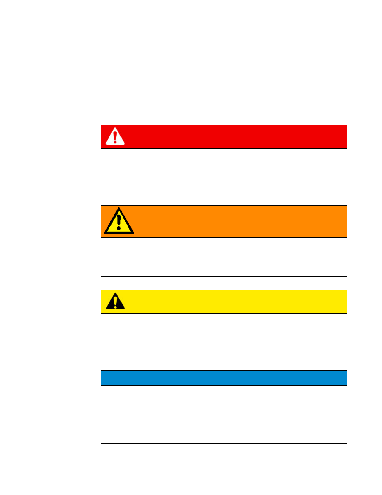
1.4 Icons and Typographic Conventions
The following safety instructions are used in this document. The sequence starts with
the most important information, and shows the importance of the messages.
A safety instruction always begins with the hazard sign, the signal word, and a text box
that explains the hazard point and gives handling instructions.
DANGER
The safety instruction DANGER stands for an extremely dangerous situation.
Nonobservance will lead to severe and even fatal injuries (burns, for example).
Observe the danger warning, and take greatest care (using protective equipment, for
example) to face the danger. Persons must work very carefully in this area.
WARNING
The safety instruction WARNING stands for a very dangerous situation.
Nonobservance can lead to severe, irreversible and even fatal injuries, and loss of
limbs.
Observe the danger warning, and take greatest care (using protective equipment, for
example) to face the danger.
CAUTION
The safety instruction CAUTION stands for a dangerous situation. Nonobservance
can lead to injuries or material damage.
Observe the danger warning, and take greatest care (using protective equipment, for
example) to face the danger.
NOTE
The safety instruction NOTE refers to situations that can lead to material damage.
They show how damage can be avoided.
Safety instructions

Hardness Tester
Introduction
DuraJet 10 G5
1-6
The following icons and typographic conventions are used in this instruction manual:
Crushing hazard
indicates a risk of crushing, threatening life and limb of persons.
Electric current
indicates a risk of electric current, threatening life and limb of persons.
Danger
indicates a risk that threatens life and limb of persons.
Note
indicates a risk of damage to property, or the need to proceed with special care.
Information
indicates additional information and tips
Bold
indicates menu options and button labels
Italics
indicate names, software programs or figure titles
Monospace
indicates system output
"Inverted commas"
indicate chapter titles and terms of particular
importance
indicates a necessary work step
Icons
Typographic
conventions
Hardness Tester
Introduction
DuraJet 10 G5
1-7
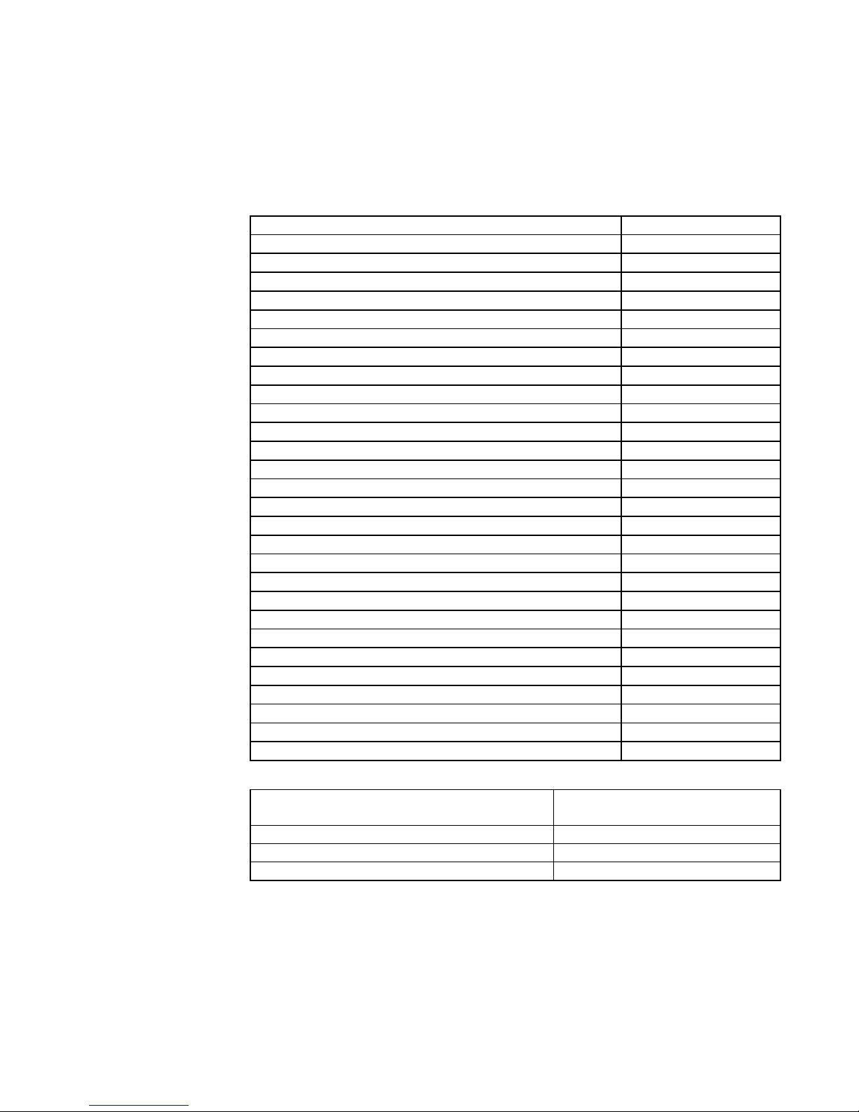
1.5 Technical Data
Test loads
[N]
9.8-2450N
[kgf]
1-250kg
Test anvil/nose cone/test unit
Test unit drive [1]
DC motor
Standard support [mm]
Diameter 25
Nose cone support [mm]
Diameter 15
Nose cone drilling [mm]
Diameter 8
Test anvil dimensions
Width x depth [mm]
180 x 185
Throat depth [mm]
175
Test height [mm]
260
Max. weight of workpiece [kg]
100
Power supply [V]
110 V / 230 V
Max. voltage fluctuations [%]
+6/-10
Frequency [Hz]
50/60
Max. power consumption [W]
max. 120 W
Main fuse rating at 230 V [A/T]
T 6.3 A
Main fuse rating at 110 V [A/T]
T 6.3 A
Touch screen [inches]
7 in.
Dimensions
Basic unit (WxHxD) [mm]
300x740x562
Footprint (WxD) [mm]
700x900
Weight of basic unit [kg]
approx. 110
Ambient conditions
Room temperature [°C]
5-40
Rel. humidity (non-condensing) [%]
up to 90
Protection category EN60529 [1]
IP20
The machine adjusts automatically to the voltage variant.
Voltage
230V~1/N/PE 50/60 Hz
110V~1/N/PE 50/60 Hz
Max. voltage fluctuations
+6%/-10%
Power consumption
120 W
Fuses
T 6.3 A
Technical data
Electrical power supply
Hardness Tester
Introduction
DuraJet 10 G5
1-8
DANGER
Electric current
Connect the machine only to a grounded electrical outlet with a protective earth
conductor contact.
Any intervention in the electrical/electronic part of the unit is prohibited.
Circuit diagram
Hardness Tester
Startup
DuraJet 10
2-1
2 Startup
2.1 Transporting the Machine
The machine is delivered on a pallet. Its outer packaging varies depending on the
country of delivery and the delivery agreements.
Remove the packaging.
Use a lifting vehicle to move the machine on the pallet.
WARNING
Overturning parts with improper transport.
Severe injuries from overturning parts.
Secure the unit with bolts on the pallet.
Transport the unit only on the pallet and with a lifting vehicle.
Unpacking the machine
Hardness Tester
Startup
DuraJet 10
2-2
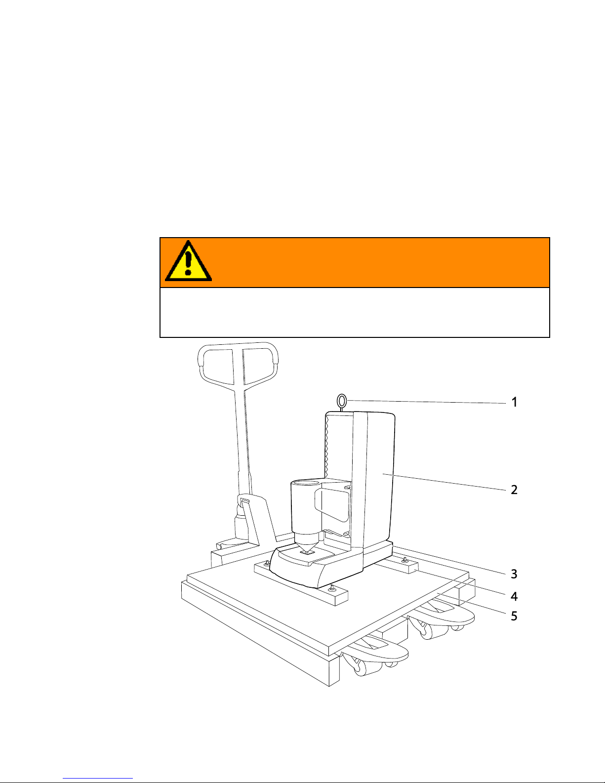
1
Ring bolt with 10 mm thread for transportation by crane
2
Hardness testing machine
3
Serial number of the unit
4
Transportation rails
5
Pallet for transporting with lifting vehicle
2.2 Scope of Supply
▪ Inspect the machine for any damage that may have occurred during transportation,
and check the delivery for completeness.
▪ If you detect any defects or discrepancies, contact your supplier or insurance
provider immediately.
▪ Please specify the serial number of the machine when you make a complaint. You
can find this serial number on the rating plate at the rear of the machine.
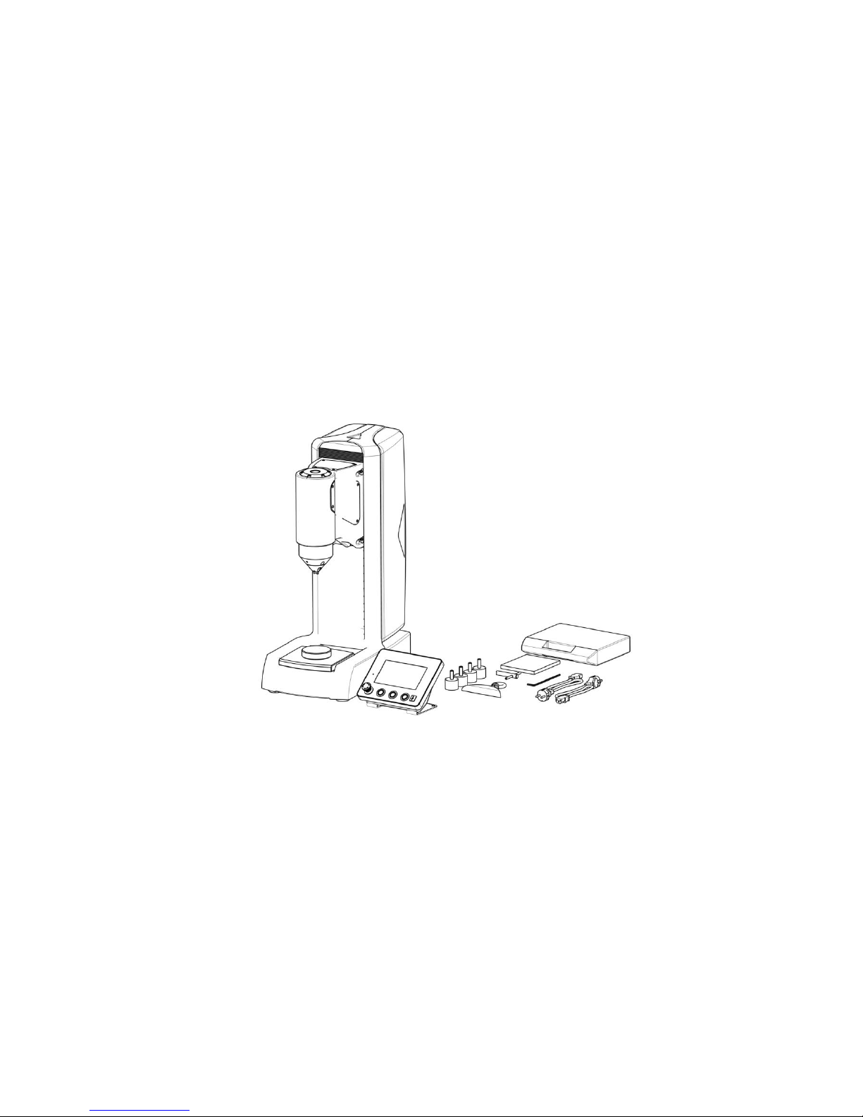
▪ Hardness tester with mounted nose cone
▪ Standard XY table DM 90mm
▪ Control part with 7-in touch screen
▪ 4x feet
▪ Cover for ring-bolt hole
▪ 2 power cables (EU/US plugs)
▪ 2 replacement fuses (slow-blow 6.3 A)
▪ 1 socket head wrench (Allen wrench)
▪ 1 socket wrench for changing the indenter
▪ CD-ROM with machine data, certificate and documentation
▪ Ring bolt
Optional accessories
▪ Indenter
▪ Nose cone
▪ Test anvils
Inspecting the delivery

Hardness Tester
Startup
DuraJet 10
2-3
If you ordered an indenter, it is included in the delivery and must be mounted.
To order additional accessories and replacement parts, contact your supplier. Only
approved products have been tested for use with this machine.
▪ Calibrated test blocks
▪ Test anvils
▪ Nose cones
▪ USB printer
▪ USB hub
▪ USB flash disk (USB stick)
Hardness Tester
Startup
DuraJet 10
2-4
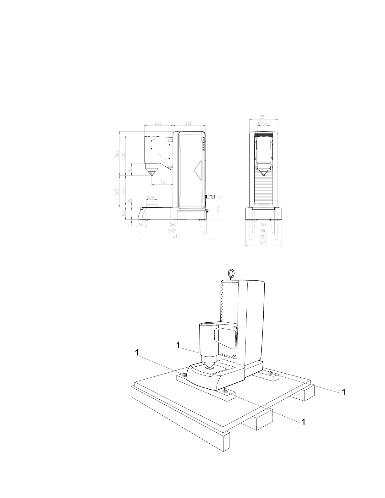
2.3 Weight and Dimensions
excluding pallet and transportation rails: approx. 110 kg
including pallet and transportation rails: approx. 150 kg
2.4 Installing the Machine
Weight and dimensions
Lifting the machine off
the pallet

Hardness Tester
Startup
DuraJet 10
2-5
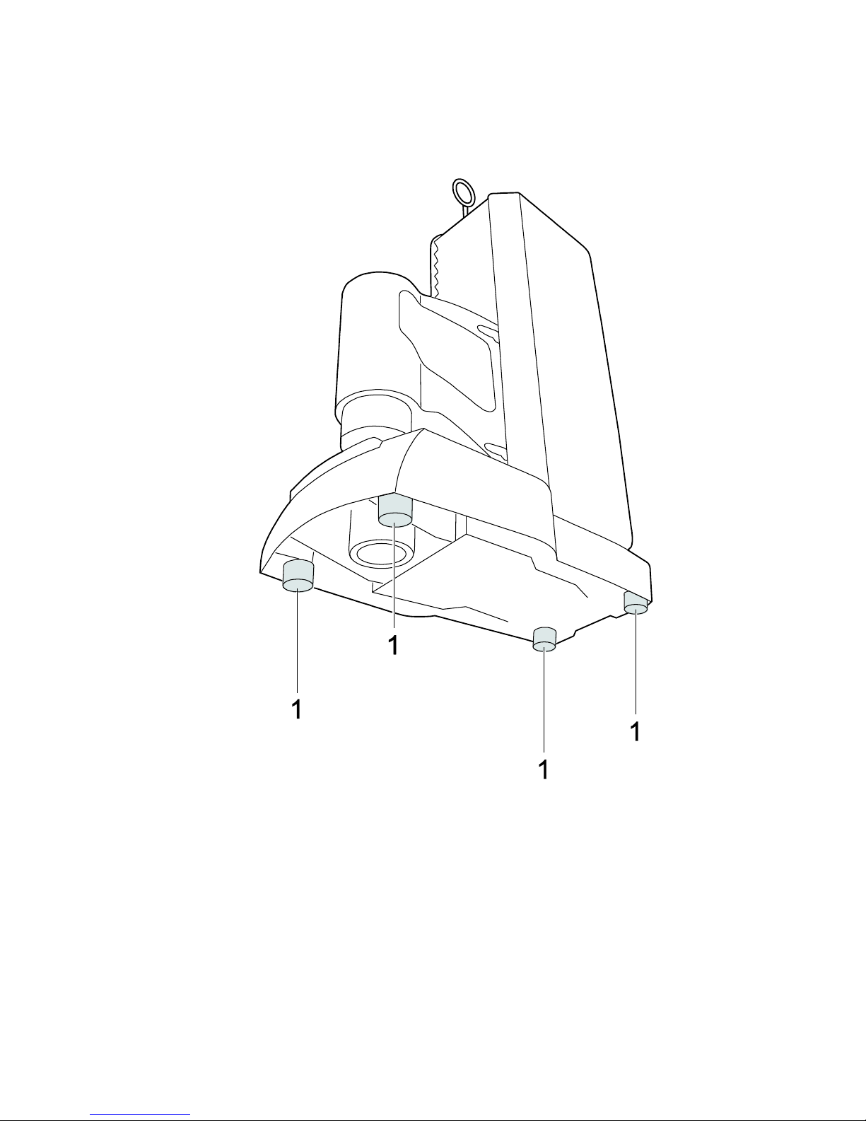
Loosen the four fastening screws (1).
Use a crane to lift the machine off the pallet by the ring screw.
Hardness Tester
Startup
DuraJet 10
2-6
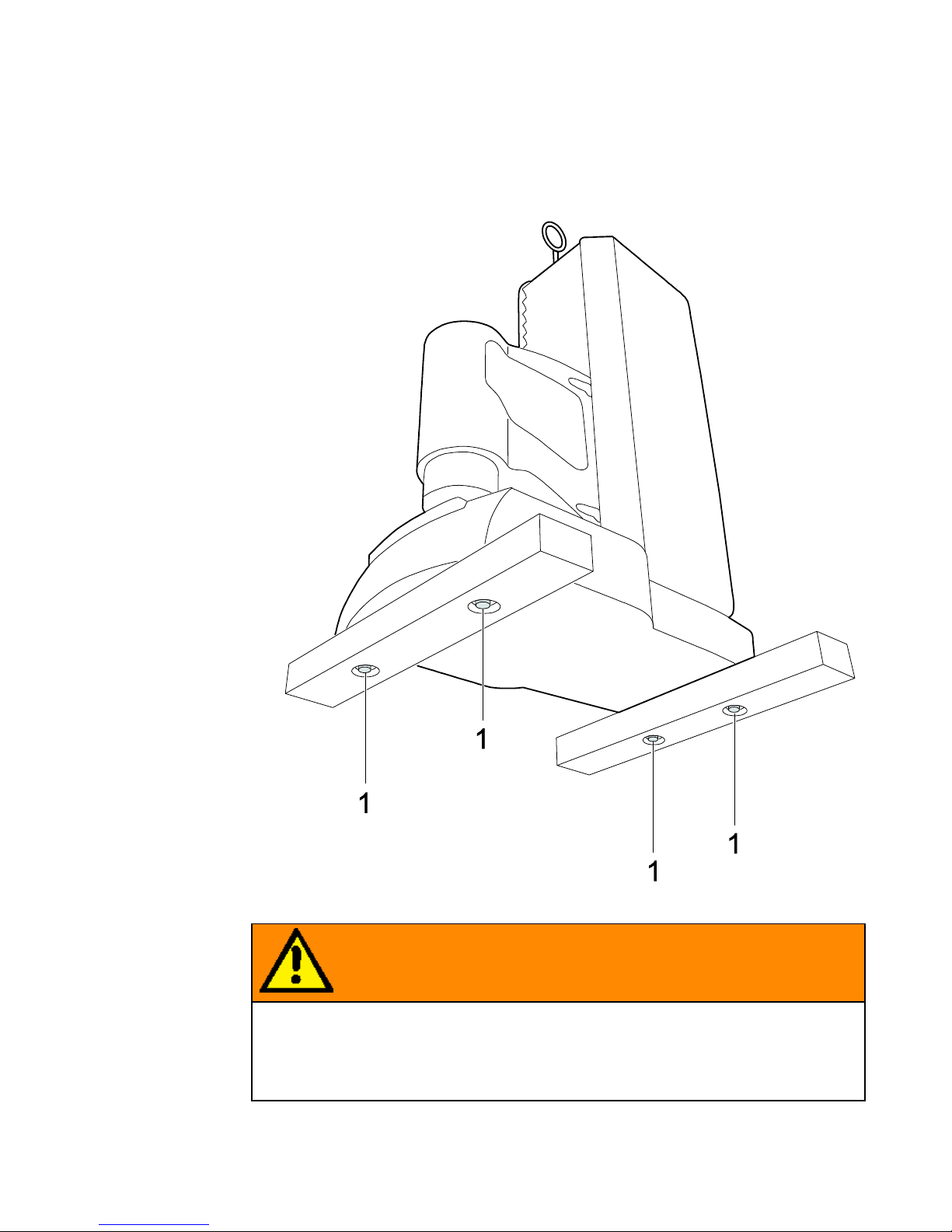
Two transportation rails are screwed onto the machine in place of the feet.
Use a crane to lift the machine.
WARNING
Dropping parts.
Severe injuries of head and limbs.
When using a crane for lifting, never exceed the maximum lifting capacity of the rope or
chain.
Ensure that nobody stays under the suspended load.
Put down the unit on 2 assembly stands.
Remove the screws (1) fastening the transportation rails and remove the rails.
Removing the
transportation rails
Hardness Tester
Startup
DuraJet 10
2-7
Screw the feet provided (1) to the unit while the unit is still suspended from the
crane and is supported by the assembly stands.
Otherwise, it is difficult to attach the feet because the unit weighs 110 kg and lies flat on
any surface when the feet are not attached.
The bench on which the machine is installed must meet the following requirements:
▪ The bench must be level and have a height of approx. 700 mm.
▪ It must be capable of supporting at least 220 kg.
During installation, allow sufficient space for operating the machine and for carrying out
possible maintenance work.
The machine must be professionally installed.
Attaching the feet
Installing the machine
Hardness Tester
Startup
DuraJet 10
2-8
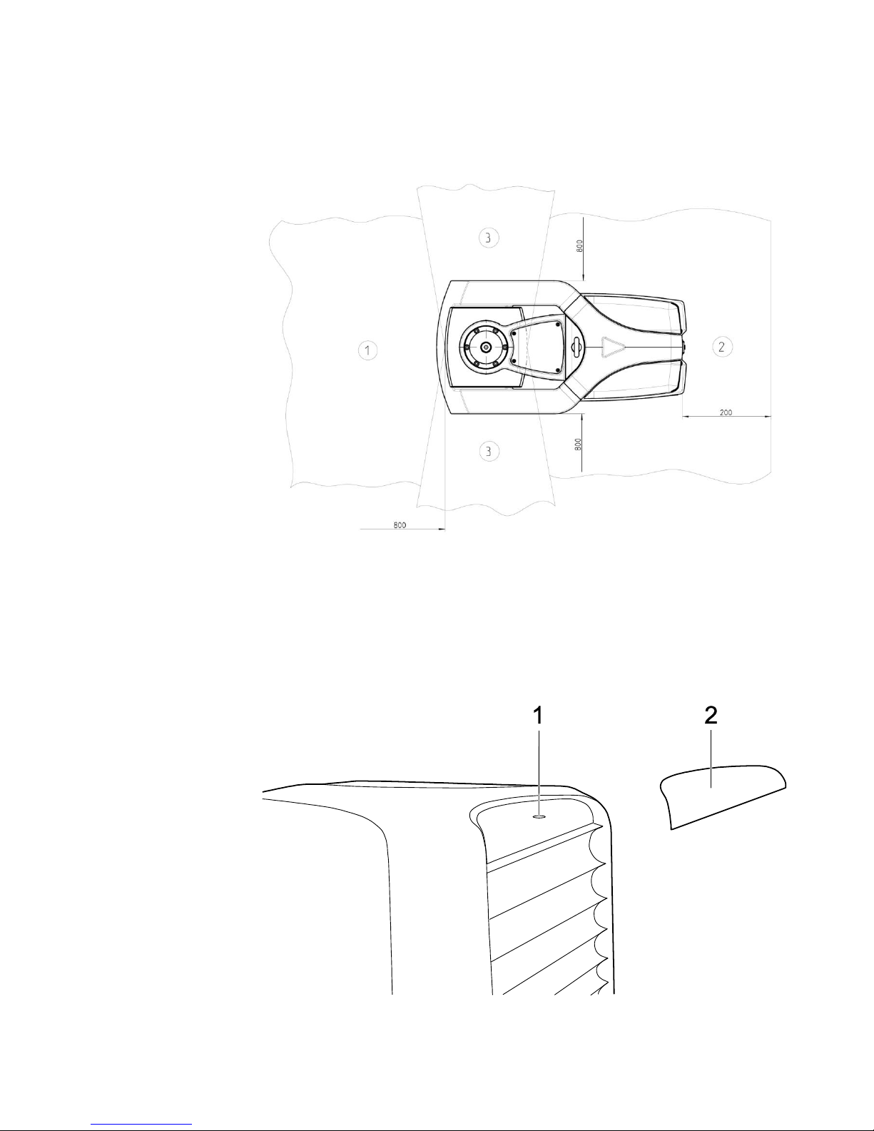
1
Space required for operation
2
Space required for maintenance
3
Space required for workpiece feed
The machine's ergonomic design is intended to optimize operation.
▪ During installation, ensure that the work station has adequate lighting.
▪ Avoid direct glare (dazzling light sources within the operator's line of vision) and
reflected glare (reflections and light reflexes) on the touch screen.
Remove the ring bolt.
Secure the cover (2) over the ring bolt (1).
The cover is supplied with a Velcro fastener.
Attaching the cover
Hardness Tester
Startup
DuraJet 10
2-9
2.5 Initial Startup
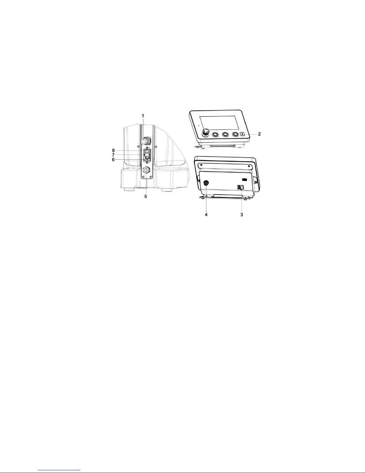
Connections on the units
1
Hardware interface (option)
2
USB connection
3
Ethernet interface
4
Control unit connection
5
Control unit connection
6
Mains connection
7
Fuses
8
Main ON/OFF switch with indicator lamp
Turn the main switch to OFF.
Plug the connector of the fixed control unit cable into the connection on the control
unit.
Ensure that the control unit cable is firmly screwed into place.
Plug the power cable into the mains connection.
Plug the opposite end of the power cable into a grounded electrical outlet with a
protective earth conductor contact.
Turn the main switch to ON.
To release the EMERGENCY OFF button on the control unit, turn it clockwise.
The software starts the initialization process.
Connecting the unit
Switching on the unit

Hardness Tester
Startup
DuraJet 10
2-10
After one to two minutes, the initial screen appears on the touch screen monitor of the
control unit, followed shortly afterwards by the main menu.
The default language of the software is English. If you want to use the software in a
language other than English, you must configure this first.
Select the button with your finger or with the touch pen.
The following screen appears on the touch screen monitor:
Select the button Settings.
Selecting language units
Hardness Tester
Startup
DuraJet 10
2-11
Select the button Open.
Select the language German.
Select the unit mm.
Language and unit have been selected.
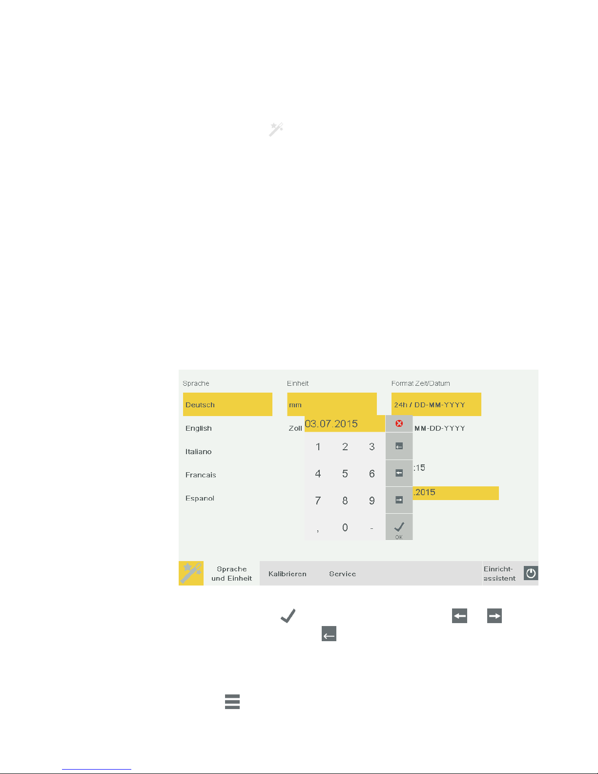
Select data and time in the right column.
Select Time or Date.
Enter the current data and time in the numeric box. Touch the button to abort
the input. Touch the button to confirm the input. Touch the and buttons
to move the cursor. Touch the button to delete the number to the left of the
cursor.
Date and time are selected and the settings are completed.
Touch the button back to configuration.
Touch back to measuring.

Hardness Tester
Startup
DuraJet 10
2-12
The three buttons Nose Cone Up, Nose Cone Down, and Start Testing on the control
unit are only active when measuring mode is activated.
Select the Testing button with your finger or with the touch pen.
The unit is now operating in a measuring mode and you can use the Nose Cone Up,
Nose Cone Down buttons on the control unit to move the test unit up or down.
Touch the Test button
DANGER
Risk of crushing from dropping test unit.
Crushed hands, arm, or fingers.
Keep your hands away from the area around the moving test unit.
Use the Nose Cone Up button on the control unit to move the test unit upwards
until you can easily reach the nose cone.
Remove the transportation safety device (cardboard padding) from the test anvil.
If you ordered an indenter, it is included in the delivery and must be mounted.
Caution
Use the main switch to turn the tester off before mounting or dismounting the indenter.
Turn the main switch to the OFF position.
Activating the
measuring mode
Mounting the
indenter
 Loading...