

Page 1
Page 2

HBS Operating Instructions Version 1.0
Page 2 of 36
Page 3

HBS Operating Instructions Version 1.0
Page 3 of 36
Contents
1. Preface .............................................................................................4
2. Safety Instructions..........................................................................5
3. What does HBS stand for?.............................................................6
4. HBS Connection Scheme...............................................................7
5. Characteristics ................................................................................8
5.1. Usage in an Electrical Motor Powered Model..........................8
5.2. Usage in a Combustion Engine Powered Model...................11
6. Recommended Accessories ........................................................ 15
7. Mounting........................................................................................ 16
8. Connecting the Supply Batteries.................................................16
9. Connecting the Receiver Battery.................................................17
10. External Status-LED.................................................................... 19
11. Mounting Examples ....................................................................19
11.1. Electrical Powered Model....................................................20
11.2. Electrical Powered Model with Dual Supply ........................20
11.3. Combustion Engine Powered Model ...................................21
11.4. Combustion Engine Powered Model with Dual Supply........22
12. Operating .....................................................................................23
13. Storage-Mode ..............................................................................25
14. Summarizing the HBS-Functions .............................................. 27
15. LED-Codes (Error- and Status Indications).............................. 28
15.1. Ext. LED at "Status Output".................................................29
15.2. Internal LED "Status"...........................................................30
15.3. Summary Table ...................................................................30
16. HBS Block Diagram .................................................................... 32
17. Technical Data of the HBS ......................................................... 33
18. Warranty.......................................................................................35
19. Declaration of Conformity..........................................................36
20. Disposal of Equipment ............................................................... 36
21. Legal Instructions .......................................................................36
Page 4

HBS Operating Instructions Version 1.0
Page 4 of 36
1. Preface
With this PowerCube ® HBS (Hybrid Battery Supply) you purchased
a high grade, modern and secure power supply system. We appreciate
your trust and assure you that you made the right choice!
More than 25 years of experience in development and manufacturing
of electronically systems, knowledge of the world’s best model airplane
pilots as well as the experience in UAV's has influenced the
development of EMCOTEC products. All products are manufactured at
EMCOTEC GmbH in Germany on our own production line. Extensive
optically and electronically end tests for every system, which leaves
our house, assure that you, our customer acquire an absolute reliable
product, which considerably increases the reliability of your valuable
RC-Model.
Of course, the products not only have been tested extensively in the
laboratory, but also went through intensive flight-testing. Like done in
the automobile industry an FMEA (Failure Mode and Effect Analysis)
reduce the possibility of damage and malfunction on operating errors to
a minimum.
We kindly ask you to read these operating instructions carefully and to
observe the installation hints. Thus, errors can be avoided in advance.
We are all ears for your wishes and questions. Challenge us!
Wehringen, May 2013
The Staff of EMCOTEC GmbH
Page 5

HBS Operating Instructions Version 1.0
Page 5 of 36
2. Safety Instructions
In general, all connecting lines should be run so that they do not
come into contact with moving or hot parts of the model (such as
servos, gears or mufflers).
The HBS (20V…75V) can be driven by high voltages but must be
according to IEC 60449 rules. This partial range of low voltage is
generally known as low tension current or light current. The limits
for direct current (DC) are ≤ 120 V. These values correspond to
continuously permissible effective touch voltages for adults and
are considered not life-threatening under normal circumstances.
For voltages greater than 60 volts DC all current leading cables
should be isolated and protected against touching.
The HBS must be protected from humidity and moisture.
The HBS must have sufficient distance to neighboring areas, in
order to allow for good heat dissipation.
Improper handling of the HBS can result in serious damage/injury
to property or persons!
Carry out a general inspection of all connections in your model
before each use! All plugs must be correctly polarized and have
clean contacts (i.e. fit tightly). Loose cables present a potential
hazard!
Under no circumstances may power sources be used that do not
meet the specified voltages.
The current-conducting contacts of the connector plugs may not
be short-circuited. If you fail to observe this warning, the shortcircuited cables may overheat and even melt.
The HBS may not be taken apart or technically altered under any
circumstances.
Never use the HBS for purposes other than for RC model making
as a hobby. Above all, their use in passenger-carrying equipment
is strictly prohibited.
Operate the HBS only with components provided for model
making (or UAS).
Page 6

HBS Operating Instructions Version 1.0
Page 6 of 36
Always ensure that you have fully charged batteries when
operating your model. Empty batteries inevitably lead to failure of
the RC components, which cause the model to crash.
Do not expose the HBS to any extremely hot or extremely cold
temperatures, moisture or humidity. This would lead to danger of
malfunction, damage or decreased efficiency.
Only use accessories approved by EMCOTEC with the HBS.
3. What does HBS stand for?
HBS stands for Hybrid Battery Supply. Hybrid means "bundled,
interbred or mixed". In this case, it relates to the voltage supply of the
receiver equipment or other components in a RC model or UAS
(Unmanned Aerial System).
The supply voltage of the HBS is generated by the flight battery of an
electrical powered model or another power source (e.g. generator). It is
actually a kind of BEC (Battery Elimination Circuit). Additionally, this
supply voltage is "interlaced" with a regular 2-cell Lithium-Polymer
battery. This additional battery serves as a buffer; it provides for high
current peaks and makes sure, that there is enough energy in case the
flight battery is empty or breaks.
Of course, the usage of the HBS is not limited to electrically powered
models. Stay tuned for more later on.
Page 7
HBS Operating Instructions Version 1.0
Page 7 of 36
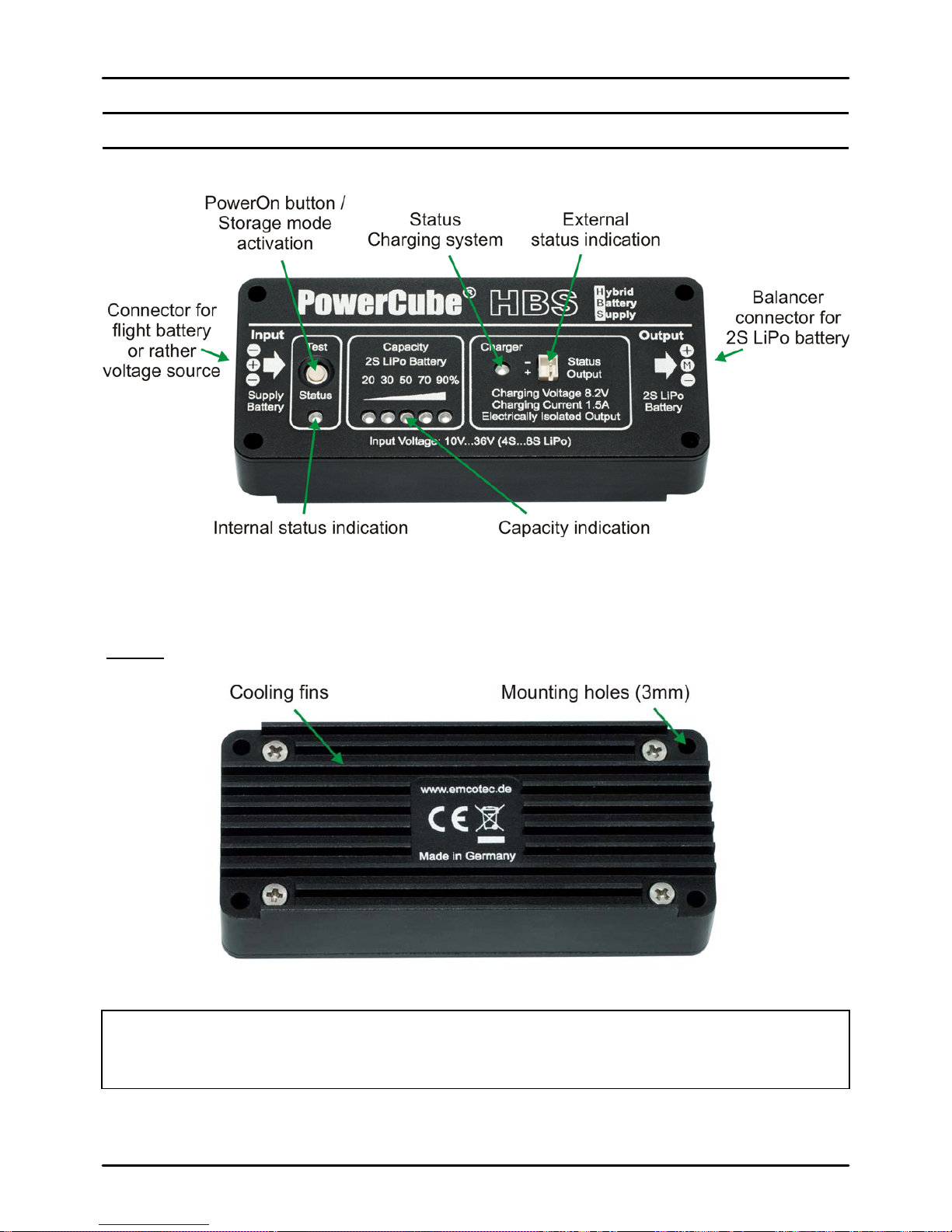
4. HBS Connection Scheme
Rear:
Hint:
The HBS can get very hot depending on withdrawn power. Therefore, the total
aluminum housing is used as heat sink.
Page 8

HBS Operating Instructions Version 1.0
Page 8 of 36
5. Characteristics
The HBS is available in two versions mend for different usages. Both
systems differ only in their input voltage range.
Version 1: HBS with 10V … 36V input voltag e
• Intelligent energy management system for combustion
powered models.
• Entire BEC substitute for electrical flight applications in
connection with a 2S LiPo buffer battery
Version 2: HBS with 20V … 75V input voltag e
• Entire BEC substitute for electrical flight applications in
connection with a 2S LiPo buffer battery
Hint:
The HBS is a totally new system and therefore remains under legal protection of
registered designs at the German patent office (Nr. 20 2013 000 114.2)
First, the function for electrical flight (BEC substitute) will be shown for
better appreciation as follows.
5.1. Usage in an Electrical Motor Powered Model
Charging of all batteries in an electrical powered model
Background of the development of the HBS is the necessity to
additionally charge the receiver battery in electrical powered models. In
huge models with redundant supply (battery switching operation) even
two receiver batteries must be charged in order to charge all batteries.
This causes a lot of work and thoughtfulness.
Page 9

HBS Operating Instructions Version 1.0
Page 9 of 36
Right here the HBS adds to it: It disburdens the pilot's everyday life
remarkably and makes sure there are less or even no errors during
charging of the batteries.
BEC was yesterday – HBS is today
The reason for the PowerCube ® HBS is to supply the receiver
equipment out of the flight battery similar to a BEC. Additionally, a
small receiver battery when mounted inside the model which actually
serves as buffer provides for high current peaks and serves for
reliability in case the flight battery is empty or malfunctions.
The receiver set is actually supplied by the HBS while the receiver
battery (2S Lithium-Polymer battery) serves for safety and is recharged
by the HBS at the same time. Manual charging of the receiver battery
is eliminated, as well as cell matching, which is done by the HBS, too.
The flight battery supplies the HBS. The DC/DC converter in the HBS
reduces the voltage of the flight battery to the charging voltage of the
2-cell LiPo battery which is directly connected to the balancing
connector of the HBS.
As soon as the flight battery is connected the HBS starts charging the
receiver battery – fully automatically. Charging current is 1.4 amps.
Simultaneously to charging, both cells of the receiver battery are
matched (equalizing function).
The receiver set gets its current via the receiver battery (when using a
battery switch via two receiver batteries with a HBS each) additionally
from the HBS (=> hybrid solution). Due to the HBS, the receiver
battery can be very small which practically leads to a weight neutral
solution. A 450mAh to 800mAh battery fully suffices – for huge models
2 batteries when using dual current supply operation.
Page 10

HBS Operating Instructions Version 1.0
Page 10 of 36
The HBS constantly recharges the receiver battery, thus, the receiver
battery is rarely discharged. Only when the flight battery fails, the
receiver set is supplied by the receiver battery only.
Hint:
As long as the average of the withdrawn current is lower than 1.4 amps (average
current consumption of the receiver set) the system acts as an "unlimited" big
receiver battery. The disadvantages of separate charging and balancing of the
(receiver) battery are eliminated.
The charging end voltage is 8.2 volts instead of normally 8.4 volts. This
reduces the usable capacity slightly but increases life expectancy
(charging cycles) significantly – similar to the batteries in a hybrid
vehicle. Here too, the bandwidth of the battery is not fully utilized in
order to increase life duration.
Extremely high Currents
The difference to a regular BEC without receiver battery is that, due to
the usage of a 2S Lipo battery, high current peaks are possible which a
BEC can not deliver. An 800mAh / 30C LiPo battery delivers 24 amps
continuous current. No BEC can do that! Additionally, the circuitries of
the flight battery and the receiver set are totally electrically separated
by the HBS. The advantages of motor controllers with optically isolated
couplers fully remain. The biggest advantage of the HBS compared to
a BEC is, that the receiver set works totally normal should the flight
battery fail because it is then supplied by the receiver battery.
The HBS is available in two versions which differ in their input voltage
range. Both versions apply to electrical flight; the version with the
smaller input voltage range applies for applications without electrical
drive as well.
Page 11

HBS Operating Instructions Version 1.0
Page 11 of 36
5.2. Usage in a Combustion Engine Powered Model
The HBS also works perfectly for motor models and jets – but is used
differently than in electrically powered models.
In a combustion engine powered model the HBS does not work as
hybrid supply but rather as a charger / equalizer which is constantly
mounted into the model. Charging of the receiver battery (or ignition /
turbine battery) is conducted by connecting an external voltage in the
range of 10 volts up to 36 volts (e.g. car battery, truck battery, solar
panel, 4S – 8S Li++ battery or any other voltage supply).
Integrated charging station in combustion engine powered model
Due to the circuitry design of the HBS a fully electrically isolation
(galvanic separation) of the input voltage (Input) and the output voltage
(Output) is accomplished.
Hint:
The output voltage (Output) of the HBS is galvanic separated from the input
voltage (Input) (electrically isolated).
Fully automatically charging several batteries with one single connector
In a model with e.g. three LiPo batteries (two for the receiver set and
one battery for ignition or turbine) three HBS are to be built in (one
HBS for each battery). All Inputs (Input) of the HBS' are connected
together and put onto one single charging connector (e.g. EMCOTEC
Part No. PC4205).
Now one single car battery suffices to be connected and all three
batteries are charged simultaneously and automatically!
Page 12

HBS Operating Instructions Version 1.0
Page 12 of 36
Because no charging program, no cell number and no charging current
must be selected and no balancer must be connected, charging is
simple as never before and can be conducted practically after every
flight. Simply connect a car battery after landing the model – ready.
Due to recharging after every flight, batteries can be much smaller as
usual. This leads to a weight neutral solution because the additional
weight of the HBS is compensated by the smaller batteries.
Battery State Indication
The charging state of the (receiver) battery which is connected to the
HBS is displayed by five LED's, operating state by 2 additional LED's.
In order to assess the remaining capacity of the battery pressing the
built in button of the HBS suffices. The charging state is displayed by
the LED's before the device automatically turns off after one minute. It
is possible to connect an external LED e.g. in the fuselage's sidewall. It
is an additional advantage of the HBS that the receiver battery can be
connected unlimited times because there is no current consumption
(without flight battery or any other input voltage)!
Page 13

HBS Operating Instructions Version 1.0
Page 13 of 36
Storage-Function
A so called storage function
rounds up the performance of the HBS. If
the (receiver) battery is to be unused for a longer period of time (e.g.
winter pause) a 5 second push onto the button activates the storage
mode. Both LiPo cells of the receiver battery are then discharged to
their optimal voltage which is best for storage, fully automatically. Due
to this function, the life performance of the battery is increased
tremendously.
Cooperation with DLR
The HBS (Hybrid Battery Supply) was developed in close cooperation
with the DLR (Deutsches Luft- und Raumfahrtzentrum / German Air
and Space Center) and finds its usage in unmanned flight systems
(UAS).
Highest Safety
Due to elaborate FMEA (Failure Mode and Effect Analysis) all risks
when using Lithium-Polymer batteries could be minimized or
eliminated. The combination of the HBS with the PowerCube LiPo
batteries (Part No. PC4100 up to PC4120) therefore is absolutely safe
and long living.
Page 14

HBS Operating Instructions Version 1.0
Page 14 of 36
PowerCube batteries must not be removed from the model for
recharge and can remain built in. Just some other outstanding safety
features of the HBS are over-load protection, low-discharge protection,
equalizing, reverse polarity protection, shortcut protection, over
temperature cutoff and recognition of battery errors. The Hybrid Battery
Supply makes charging technique in a RC model as safe as never
before.
The HBS in head words
Wide input voltage range from 10-36 volts or 20-75 volts
Galvanic isolated charging system for 2S Lithium-Polymer
batteries
1.4A charging current, 8.20V charging end voltage
Integrated equalizer with storage function
Quiescent current lower than 1.5µA – Therefore no discharge of the
batteries during longer breaks
Unlimited number of parallel HBS possible. The outputs are
electrically isolated
Shortcut- and reverse polarity protected input
Shortcut protected output
Conservative Trickle-Charging for deep discharged batteries
Over-temperature cutoff
Different display modes of the charging- and battery state
Recognition and indication if battery errors
Simple control of charging state of the receiver battery with single
button press
Special ground concept for disturbance free operation and highest
safety
High grade housing milled out of a solid aluminum block which also
serves as heat sink at the same time
Perfectly suitable in combination with PowerCube LiPo batteries
Under legal protection of registered designs (German Patent Office
Nr. 20 2013 000 114.2)
Page 15

HBS Operating Instructions Version 1.0
Page 15 of 36
6. Recommended Accessories
Part No. Product
PC4100 PowerCube 450 – 2S LiPo battery, 450mAh
PC4105 PowerCube 800 – 2S LiPo battery, 800mAh
PC4110 PowerCube 1300 – 2S LiPo battery, 1300mAh
PC4115 PowerCube 1800 – 2S LiPo battery, 1800mAh
PC4120 PowerCube 2400 – 2S LiPo battery, 2400mAh
PC4230 JR/UNI battery patch cable - Variant 30cm long
PC4230 JR/UNI battery patch cable - Variant 50cm long
PC4240 PowerCube battery charging / balancing cable - Variant 10cm
PC4240 PowerCube battery charging / balancing cable - Variant 20cm
PC4200 EMCOTEC Charging Socket
PC4205 EMCOTEC Charging Socket with Status LED's
PC4220 Charging Cable for Charging Socket - Variant 180cm
PC4220 Charging Cable for Charging Socket - Variant 250cm
PC4010 PowerCube HBS Status-LED, 5mm
A86200 Vibration Damper Set (4 pieces) - Variant “A”
Page 16

HBS Operating Instructions Version 1.0
Page 16 of 36
7. Mounting
The HBS can be mounted onto a board using M3 screws. We
recommend mounting on vibration dampers (Part No. A86200). That
assures for good air flow and vibration damping.
8. Connecting the Supply Batteries
For connection of the supply voltage (= external charging voltage) on
the HBS a normal JR/Uni battery patch cable or a servo cable with
disconnected pulse line suffices. The wire cross section for low input
voltages should be up to 20 volts 0.5mm² (AWG21), for higher voltages
a cable with 0.25mm² (AWG24) suffices. The input of the HBS is
reverse polarity- and shortcut protected.
Hint:
A JR/Uni battery connection cable could be accidentally connected to the HBS
output because the spacing is nearly identical. This could lead to damage of the
HBS! Therefore always observe correct connection of the cable!
Page 17

HBS Operating Instructions Version 1.0
Page 17 of 36
9. Connecting the Receiver Battery
All 2S Lithium-Polymer batteries are suitable as (receiver)-batteries for
charging. We recommend using PowerCube LiPo batteries. These are
equipped with today's highest grade available cells from KOKAM. This
assures for very long life performance. The capacity indication of the
HBS is calibrated to PowerCube LiPo batteries and shows the most
precise results for them.
Supply voltage 2S LiPo battery
(external charging voltage) (receiver battery)
The battery is connected to the output of the HBS with its balancing
connector (JST EHR connection system). Charging current of the HBS
is limited to 1.4 amps, charging end voltage is 8.2 volts.
Page 18

HBS Operating Instructions Version 1.0
Page 18 of 36
Hint:
The charging end voltage of the HBS is 8.2 volts (although 8.4 volts are
permissible). This lowers the provided capacity of the battery by approx. 18%.
An 800mAh battery therefore has only effectively approx. 650mAh of capacity, a
battery with nominal 2400mAh just under 2Ah effective capacity.
These measuring results correspond to PowerCube batteries with KOKAM cells
at 23°C and 1C charging / discharging current.
Life performance of the batteries is tremendously increased by this lowered
charging end voltage because relevant values of the DOD (Depth of Discharge)
for life performance are far not reached.
Hint:
Only 2-cell Lithium-Polymer batteries must be connected to the HBS. Usage of
LiFePO4 batteries is impossible and not permissible!
Hint:
A receiver battery connected to the HBS is not protected against deep discharge!
Because the battery is directly connected to the consumer (e.g. battery switch or
receiver set) the HBS has no control. But a threatening low voltage is optically
indicated by LED's if the HBS is turned on.
Page 19

HBS Operating Instructions Version 1.0
Page 19 of 36
10. External Status-LED
If free sight to the HBS in the model is not possible, an external LED
(Part No. PC4010) can be connected to the output ("Status Output").
The LED can be mounted into the fuselage's sidewall and indicate
important system states of the HBS optically. The open collector output
of "Status Output" switches 5 volts and can be loaded with a maximum
of 60mA.
The EMCOTEC charging socket with status LED (Part No. PC4205)
has two integrated LED's which illuminate the outer ring of the charging
socket. The charging socket is suitable for two HBS (e.g. for dual
current supplies) and can display the status of two HBS. Contact is
accomplished directly with the connection cables of the charging
socket.
11. Mounting Examples
The following mounting examples serve as recommendation for using
a HBS in an RC model. Of course, many other variants are
considerable.
Page 20

HBS Operating Instructions Version 1.0
Page 20 of 36
11.1. Electrical Powered Model
In this example the receiver set is powered by a receiver battery.
Switches and so on are not shown.
11.2. Electrical Powered Model with Dual Supply
In this example the receiver set is powered by a dual current supply
with two receiver batteries.
Page 21

HBS Operating Instructions Version 1.0
Page 21 of 36
11.3. Combustion Engine Powered Model
In this example the receiver set is supplied by a receiver battery, the
ignition by an additional battery. The HBS isolates the two batteries in
order to avoid disturbance between the ignition system and the
receiver set.
The inputs of the HBS' lead to a central charging socket (Part No.
PC4205) which is mounted into the fuselage's sidewall. After each
flight connect an external charging cable (Part No. PC4220). The
charging cable on the other hand is directly connected to a car battery
or any other DC voltage source. Nothing is to be selected: no cell
number, no charging program, and no charging current!
The gray, dotted lines in the draft leading from the HBS' to the
charging socket indicate the connection cable for the "illumination" of
the charging socket. There are two status LED's in the charging socket
which display the actual charging state of the batteries. The user
immediately sees the charging state of the batteries.
Page 22

HBS Operating Instructions Version 1.0
Page 22 of 36
11.4. Combustion Engine Powered Model with Dual Supply
Here, the receiver set is supplied by two receiver batteries via a dual
current supply. The ignition has its own battery. Each battery is
supplied by a HBS. The inputs of the HBS' lead to a central charging
socket (Part No. PC4205) which is best mounted in the fuselage's
sidewall.
Noteworthiness of the gray, dotted lines in the draft from the HBS to
the charging socket: In this case, one LED in the charging socket
corresponds to the receiver set the other to the ignition system. For
DPSI dual current supplies from EMCOTEC both receiver batteries are
always 100% discharged identically. Therefore, it suffices to display the
state of one battery. The other battery has the same identical state
anyway.
Page 23

HBS Operating Instructions Version 1.0
Page 23 of 36
12. Operating
After finishing all connections, the HBS is activated either by applying
an external voltage or by pushing the button.
After turning the HBS on all LED's are lit for optically control ("walking
light" – LED's light in sequence). Now, the HBS tests for correct battery
connection. A missing center tap of the balancing connector is
indicated as well as a missing plus pole of the battery. Here, cabling or
contact errors are indicated immediately.
If all is correctly connected the battery is measured, its capacity is
displayed by the LED's and possibly equalizing is started in order to
bring both cells to the same voltage.
Hint:
The LED's of the capacity display show the remaining capacity of the LiPo
battery. Here, charging and recharging is differentiated, i.e. depending on state
(charging / recharging) another characteristic curve is displayed. This serves for
a very precise display.
Charging State Control
When the HBS is turned on by its button (e.g. for control of the
charging state of the connected battery) it turns itself off after one
minute automatically in order to safe current. Automatic cutoff does
NOT occur if the voltages of both cells must be equalized. Only if the
voltages of both cells are identical, cutoff occurs after another two
minutes.
Hint:
In order to test the charging state of the connected battery, turn the HBS on by its
button. The LED's of the capacity display indicate the remaining capacity of the
LiPo battery. The HBS turns itself off after one minute if balancing is not in order.
The LED "Status" below the button flashes if the HBS is turned on by
its button. A LED connected to "Status Output" flashes, too.
Page 24

HBS Operating Instructions Version 1.0
Page 24 of 36
Charging Process
If an external voltage is connected to the HBS the internal charging
system will start charging, even if the battery is fully charged. With a
fully charged battery, the charging system turns itself off after a few
minutes. The charging process is totally independent from the
equalizing function of the HBS.
In an actual
power on cycle a new charging process only starts if the
battery voltage dropped to approx. 7.8 volts. The HBS therefore could
be theoretically connected to an external power supply for days or
even weeks. A fully charged battery would not be charged at this time
and therefore life performance would be increased. Furthermore, this
serves for control, whether a receiver battery is even connected
because the receiver set is supplied power from the receiver battery
only for the first couple of minutes; this continuous until the charging
system turns on automatically.
The charging process is indicated by the continuous lit LED "Charger".
If the LED turns off, the charging process is finished or the charging
system was deactivated. For a too high temperature, the monitoring
circuitry turns the charger off. This is also indicated.
Hint:
If the capacity of the connected battery is too big and the charging time exceeds
the LED "Charger" possibly blinks. Also if the battery is deeply discharged and
the cells are damaged the LED may blink. In this case it is helpful to disconnect
and reconnect the external voltage or to test the battery.
During charging the LED "Status" blinks below the button. A LED
connected to "Status Output" displays the charging state and possible
errors by blink codes.
Page 25

HBS Operating Instructions Version 1.0
Page 25 of 36
13. Storage-Mode
Lithium-Polymer batteries should not stored fully charged during long
operating pauses (e.g. in winter times). Storing a fully charged battery
reduces its life performance considerably.
The best charging state of the battery is at delivery. Therefore, the
HBS allows reestablishing this state by a single button press.
Storage mode is only available if no external voltage source is
connected to the HBS (i.e. no external supply for charging the battery).
Turn on the HBS using button "Test". After a few seconds the charging
state of the connected battery is displayed by five capacity indicating
LED's.
Pressing the button for 5 seconds starts the Storage-Mode. This
operating state is displayed by the five inverted illuminated LED's, i.e.
all five LED's are turned on and only one LED (indicating the actual
capacity in percent) is off.
In the HBS integrated balancing circuitry discharges the battery to the
desired voltage of approx. 7.8 volts.
Page 26

HBS Operating Instructions Version 1.0
Page 26 of 36
Hint:
No external voltage must be connected to the input of the HBS because the
charging system would be activated. The storage mode then can not be activated
or will be interrupted.
The charging state of the receiver battery must be >= 70% otherwise the
Storage-Mode can not be activated.
Depending on the capacity of the connected battery it can take several
hours to reach this state. When the correct cell voltage is reached the
HBS turns itself off.
Hint:
Of course, the battery is balanced during active Storage-Mode, i.e. both cells
remain identical voltages.
An activated Storage-Mode can be manually deactivated by either
pressing the button "Test" for 5 seconds, connecting an external
voltage to the HBS (Input) or by disconnecting the battery from Output.
Recommendation:
If it is to foresee that the receiver battery is not to be used for approx. 8 weeks,
the Storage-Mode should be activated already.
Page 27

HBS Operating Instructions Version 1.0
Page 27 of 36
14. Summarizing the HBS-Functions
Power On Process
The HBS activates either via the button or by connecting an external
voltage source. All five capacity-indicating LED's (20 / 30 / 50 / 70 /
90%) turn on in sequence for 100 milliseconds.
Power Off Process
The HBS turns itself off automatically after one minute if no external
voltage is supplied and no balancing was active within this minute. The
HBS turns itself off automatically after two minutes if no external
voltage is supplied and balancing was activated at least once. The
power off process is extended for another 2 minutes as soon as the
HBS starts balancing.
Safety Functions
• If the center tap of the battery is missing the charging system
is turned off after 5 seconds automatically.
• If the internal temperature exceeds 80°C the charging
process is deactivated. Reactivation occurs when the
temperature drops below 70°C.
• The charging system deactivates if a cell of the battery
exceeds 4.205 volts. Reactivation only occurs if the cell
voltage drops below 3.7 volts!
Balancing of the cell voltages
The cell voltages of a 2S battery will be balanced / equalized down to
3.7 volts. There is no balancing below 3.7 volts. The cell which has at
least a 30mV higher voltage than the other will be discharged.
Balancing current is approx. 90mA.
Page 28

HBS Operating Instructions Version 1.0
Page 28 of 36
Storage Function
The Storage-Function is activated by pressing the button 5 seconds
and, at the same time, if there is no external voltage connected, the
center tap of the battery is connected correctly and both cell voltages
exceed 3.81 volts.
The Storage-Function deactivates by pressing the button for 5 seconds
again or an external voltage is connected to the HBS. Deactivation
takes also place if the center tap of the battery is missing or both cells
drop below 3.81 volts.
Error Conditions
• A battery cell is considered broken if its voltage drops below
2.0 volts.
• A missing center tap is detected if the voltage of the battery
cell drops below 0.2 volts. The qualifying time is 200
milliseconds.
15. LED-Codes (Error- and Status Indications)
The different states of the HBS are indicated by the internal LED's as
well as with an optional external LED (at output "Status Output").
The LED's have different meanings:
Status LED (below the button): Actual state of the HBS
Capacity indicating LED's: Charging state of the battery
Charger LED: State of the charging system
External LED (Status Output): Charging state of the battery / status
information
The internal Status-LED below the button indicates other codes than
the external LED. The external LED (e.g. LED in the optional charging
socket) has the following meaning:
Page 29

HBS Operating Instructions Version 1.0
Page 29 of 36
Charging State Control: frequent blinks: little charged so far
less frequently blinks: a lot charged so far
continuously on: battery fully charged
Error Indication: fast blinks (10 times per second)
Short Flashes: standby-operation (no ext. voltage)
Hint:
The less the external LED blinks the fuller the battery. If the LED blinks
symmetrically and constantly (1 time per second) the battery is charged more
than 90% and the model can take off. No need to wait for a constantly lit LED.
Hint:
Charging of a LiPo battery follows the principal of CC/CV, i.e. first charging
occurs with constant current, then constant voltage. When the battery is charged
up to approx. 90%, the remaining charging time to reach 100% is relatively long.
Therefore, there is no need to wait for a 100% charged battery. 90% capacity
suffices (better to observe some buffer anyway).
15.1. Ext. LED at "Status Output"
Page 30

HBS Operating Instructions Version 1.0
Page 30 of 36
15.2. Internal LED "Status"
15.3. Summary Table
State Display
Capacity-Indicating LED's: depending on battery state
Internal Status-LED: flashing (30ms on, 1500ms off)
Standby, i.e.
no external voltage
Status Output: flashing (30ms on, 1500ms off)
Capacity-Indicating LED (20%): blinking with 10Hz or
totally off when battery deeply discharged
Internal Status-LED: blinks with 10Hz
Capacity <= 10%
no external voltage
Status Output: blinks with 10Hz
Capacity-Indicating LED (20%): blinks with 10Hz
Internal Status-LED: blinks with 10Hz
Capacity < 20%
external voltage
connected (charger
active)
Status Output: 6 * (400ms on / 400ms off), then 800ms
pause
Capacity-Indicating LED (20%): continuously on, others off
Internal Status-LED: blinks (1000ms on / 1000ms off)
Capacity >= 20%
external voltage
connected (charger
active)
Status Output: 5 * (500ms on / 500ms off), then 1000ms
pause
Page 31

HBS Operating Instructions Version 1.0
Page 31 of 36
State Display
Capacity-Indicating LED (30%): continuously on, others off
Internal Status-LED: blinks (1000ms on / 1000ms off)
Capacity >= 30%
external voltage
connected (charger
active)
Status Output: 4 * (600ms on / 600ms off), then 1200ms
pause
Capacity-Indicating LED (50%): continuously on, others off
Internal Status-LED: blinks (1000ms on / 1000ms off)
Capacity >= 50%
external voltage
connected (charger
active)
Status Output: 3 * (700ms on / 700ms off), then 1400ms
pause
Capacity-Indicating LED (70%): continuously on, others off
Internal Status-LED: blinks (1000ms on / 1000ms off)
Capacity >= 70%
external voltage
connected (charger
active)
Status Output: 2 * (800ms on / 800ms off), then 1600ms
pause
Capacity-Indicating LED (90%): continuously on, others off
Internal Status-LED: blinks (1000ms on / 1000ms off)
Capacity >= 90%
external voltage
connected (charger
active)
Status Output: 1 * (1000ms on / 1000ms off)
Capacity-Indicating LED (90%): continuously on, others off
Internal Status-LED: continuously on
Battery fully charged
external voltage
connected (charger
active)
Status Output: continuously on
Capacity-Indicating LED's: depending on battery state
Internal Status-LED: flashing (30ms on, 1500ms off)
Charging system
inactive
external voltage
connected (charger
active)
External LED: flashing (30ms on, 1500ms off)
Capacity-Indicating LED's: depending on battery state
Internal Status-LED: Blinks / Flashing (1180ms on /
100ms, then flashing)
Balancing active
Status Output: depending on charging state
Page 32

HBS Operating Instructions Version 1.0
Page 32 of 36
State Display
Capacity-Indicating LED's: depending on battery state with
INVERTED DISPLAY
Internal Status-LED: blinking / flashing (1180ms on /
100ms, then flashing)
Storage-Mode
no external voltage
Status Output: flashing (30ms on, 1500ms off)
Capacity-Indicating LED's: blinks with 10Hz
Internal Status-LED: blinks with 10Hz
Center tap missing
Error Condition
Status Output: blinks with 10Hz
Capacity-Indicating LED (90%): blinks with 10Hz
Internal Status-LED: blinks with 10Hz
Over Voltage
Error Condition
Status Output: blinks with 10Hz
Capacity-Indicating LED's: depending on battery state
Internal Status-LED: blinks with 10Hz
Temperature
exceeded
Error Condition
Status Output: blinks with 10Hz
16. HBS Block Diagram
Page 33

HBS Operating Instructions Version 1.0
Page 33 of 36
17. Technical Data of the HBS
Supply Voltage
10V to 36V or
20V to 75V DC (depending on version)
Current Consumption without external Voltage at "Input" (no charging operation)
Quiescent Current (turned off)
< 1.5µA
Quiescent Current Standby
Approx. 6.5mA
Current Consumption with external Voltage at "Input" (charging operation)
Version 10-36V
Max. 1.75A @ 10V / 0.46A @ 36V
Version 20-75V
Max. 0.84A @ 20V / 0.23A @ 75V
Equalizing- und Charging System
Max. Charging Current
1.40A (+/- 5%)
End-of-Charge Voltage
8.20V (+/- 0.5%)
Equalizing Range
3.70V to 4.20V per cell
Equalizing Current
Max. 90mA per channel
Trickle Charge Mode
@ battery voltage < 5.60V
Re-Switch-On-Voltage Charger
@ battery voltage < 7.80V
Safety Functions
Temperature Shutdown
@ T >= 80°C, repeated Switch-on @ T < 70°C
Over Voltage Indication
> 4.20V per cell
Low Voltage Indication
< 3.20V per cell
Short Protection Input
Yes
Reverse Polarity Protect. Input
Yes
Reverse Polarity Protect. Output
Yes
Cutoff Voltage Converter
Version 10V to 36V: @ < 9.5V
Version 20V to 75V: @ < 17.0V
General Data
Isolation Voltage
Galvanic separated Output
> 2kV
Isolation Resistance
> 10MOhm
Status Output
Open Collector, 5V output, max. 60mA
CE-Test
According to 2004/108/EG
Environmental Conditions
-10°C .... +50°C
Permissible Temperature Range
-25°C .... +80°C
Dimensions
85mm x 37mm x 21mm (L x W x H)
Weight
Approx. 68g
Warranty
24 month
Page 34

HBS Operating Instructions Version 1.0
Page 34 of 36
Connectors
Connector Supply Voltage (Input)
JR / UNI, spacing 2.54mm, 3-pin
Connector LiPo-Battery (Output)
JST EH Series, spacing 2.5mm, 3-pin
Connector Plug Status Out
JST PH Series, spacing 2.0mm, 2-pin
Technical modifications and errors excepted!
Page 35

HBS Operating Instructions Version 1.0
Page 35 of 36
18. Warranty
EMCOTEC GmbH shall issue a 24-month warranty on the "HBS". The guarantee
period shall begin with delivery of the equipment by the retailer and shall be not
extended by any guarantee repair or guarantee replacement.
During the period of guarantee, the warranty shall cover the repair or
replacement of any proven manufacturing or material defects at no charge. There
shall be no specific entitlement to repair work. In case of a guarantee claim, the
manufacturer shall reserve the right to exchange the equipment for a product of
equal value if repair of the item is not feasible for economic reasons. There shall
be no assumption of liability for consequential damages that are brought about by
a proven defect during operation of the "HBS". There shall be no extended
claims for damages.
All transportation, packaging and travel expenses shall be borne by the
purchaser.
No liability shall be assumed for any damages during transport.
If repair is needed, the equipment must be sent to the appropriate service
center of the respective country or directly to EMCOTEC GmbH.
The guarantee shall only be valid when the following conditions are met:
The guarantee document (original invoice) must include the delivery date,
the company stamp, the serial number and signature of the retailer.
No intervention in the equipment may have been undertaken.
It must have been operated in accordance with our operating instructions.
Only the power sources and other accessory devices and components that
were recommended by us may have been used.
The guarantee document, the original invoice and other pertinent
information regarding the malfunction (a short description of the defect)
must be included with the transmittal.
The equipment must still be the property of the initial purchaser.
If equipment is sent in that later proves to be functional following an initial
inspection, we shall impose a flat processing fee of € 15.
In all other respects, the general business terms and conditions of
EMCOTEC embedded controller technologies GmbH shall apply for any
items not listed.
Page 36

HBS Operating Instructions Version 1.0
Page 36 of 36
19. Declaration of Conformity
EMCOTEC GmbH hereby declares that this product satisfies the fundamental requirements
and other relevant regulations contained in the appropriate EU directives. The original
Conformity Declaration can be viewed on the Internet under http://shop.rc-electronic.com
which is included in each device description.
20. Disposal of Equipment
It is illegal to dispose of electronic equipment in the ordinary household waste: that is the
meaning of the symbol printed alongside. It simply means that you must dispose of electrical
and electronic equipment separately from the general household waste when it reaches the
end of its useful life. Take your HBS to your local specialist waste collection point or recycling
centre. This applies to all countries of the European Union, and to other European countries
with a separate waste collection system.
21. Legal Instructions
Trademarks:
The following names are registered trademarks: EMCOTEC / DPSI / PowerCube
Other product names mentioned in this manual may also be trademarks or registered
trademarks of their respective owners.
Copyright information:
This manual is copyrighted by EMCOTEC GmbH. All rights reserved. This document may not
be copied either entirely or in part, nor may it be transferred to any type of medium or
translated into any other language without the express written approval of EMCOTEC GmbH.
Manual Note:
EMCOTEC GmbH reserves the right make changes to this manual and to equipment
described herein without notice. Considerable effort has been made to ensure that this manual
is free of errors and omissions. We shall not assume responsibility or liability for any errors that
may be contained in this manual nor for any incidental, concrete or consequential damage that
may arise from the provision of this manual, or the use of this manual in operating the
equipment, or in connection with the performance of the equipment when so operated.
 Loading...