

Page 1
Page 2

DPSI TWIN Mini Operating Instruc tions Version 1.0
Page 2 of 36
Table of Contents
1. Preface .............................................................................................3
2. Characteristics ................................................................................4
2.1. Functional Description.............................................................4
2.2. Safety Considerations & Quality..............................................6
2.3. Connections.............................................................................8
3. Properties of the DPSI TWIN Mini................................................ 11
3.1. Data Logger...........................................................................12
3.2. Functional Principal of the Switching..................................... 13
4. Packing Contents..........................................................................16
5. Mounting Details ...........................................................................16
5.1. Mounting of the DPSI TWIN Mini...........................................16
5.2. Connecting the Receiver ....................................................... 17
5.3. Arranging the Antennas.........................................................18
5.4. Current Supply and Servo Connections ................................ 19
5.5. Failsafe Channel....................................................................25
6. Beginning of Operation ................................................................ 25
7. Error Indications ...........................................................................26
8. Programming.................................................................................27
8.1. Firmware-Update...................................................................29
9. Application Examples...................................................................30
10. Safety Instructions...................................................................... 32
11. Technical Data of the DPSI TWIN Mini ...................................... 33
12. Warranty.......................................................................................34
Page 3

DPSI TWIN Mini Operating Instruc tions Version 1.0
Page 3 of 36
1. Preface
With the DPSI TWIN MINI you purchased a high grade, modern and
secure product for your valuable radio controlled model. We apprec iate
your trust and assure you that you made the right choice!
Long lasting experience for years in development and manufacturing of
electronically systems as well as the knowledge of the world’s best
model airplane pilots has influenced the development of the DPSI
TWIN MINI systems. All products are manufactured at EMCOTEC
GmbH in Germany on our own pr oduction line. Extensive optically and
electronically end tests for every system, which leaves our house,
assure that you, our customer, acquire an absolute reliable product
which considerably increases the reliability of your valuable RC-Model.
Of course, the DPSI TWIN MINI not only has been tested extensively
in the laboratory, but also went through intensive flight-testing. Like
done in the automobile industry an FMEA (failure mode and effect
analysis) reduces the possibility of damage and malfunction on
operating errors to a minimum.
Hint:
We kindly ask you to read these instructions carefully and to observe the
installation hints. Thus, errors can be avoided in advance.
We are all ears for your wishes and questions. Challenge us!
Bobingen, September 2007
The Staff of EMCOTEC GmbH
Page 4

DPSI TWIN Mini Operating Instruc tions Version 1.0
Page 4 of 36
2. Characteristics
2.1. Functional Description
The DPSI TWIN Mini provides a kind of ”Receiver diversity“. Two
receivers can be connected. The receiver with undisturbed radio
reception provides for the servos signals. If this receiver fails, the
signals for the servos are provided from the other undisturbed receiver
by automatic switch over. Therefore, the model remains fully
controllable if a receiver fails. In summary, 16 channels are switched
completely. The DPSI TWIN Mini can be operated stand-alone or in
conjunction with the battery-switches from then EMCOTEC’s DPSI
product range.
Several applications are possible with the DPSI TWIN Mini:
1. Failsafe-Function “A“:
(Two identical receivers using same frequency)
If one receiver fails, all (!) servos are switched to the second receiver.
The pilot can continue his flight without disturbances or adverse
effects. The receivers should feature a failsafe function (e.g. PCM).
Even by using two PPM (or IPD) receivers without failsafe capability,
switching of the servo signal can occur caused by a disturbed (or
missing) servo signal.
2. Failsafe- Function “B“:
(Two receivers using different frequencies, e.g. using the EMCOTEC HF TWIN)
If one receiver fails OR channel double-allocation occurs, all servos are
switched to the second (backup) receiver.
3. Pilot-Backup:
(Two receivers and two transmitters using different frequencies)
If the receiver OR the transmitter of the pilot fails, all servos are
switched to the second (backup) pilot. He can then land the model
safely.
Page 5

DPSI TWIN Mini Operating Instruc tions Version 1.0
Page 5 of 36
4. Teacher-Student-Function:
(Two receivers and two transmitters using different frequencies)
The teacher switches between his and the students radio back and
forth by using a switching channel of his transmitter. The student can
now take over all functions of the model with his transmitter (passing
single
functions to the student are not possible). The teacher can gain
full control with one single switching event in critical situations.
Herewith, each model-pilot can fly his friend’s model (which has
installed the DPSI TWIN MINI) with his own radio using his own stick
assignment. He just must program the model parameters into his radio.
5. Autopilot for Drones (UAV´s):
(Regular remote radio control and an autopilot)
The pilot switches between the receiver and the autopilot by using a
switching channel on his radio. The drones therefore can takeoff and
land under control of a regular remote control and be switched to the
autopilot on demand to fly its corresponding program.
Additional Functions:
Additionally, the DPSI TWIN Mini works as data logger, i.e. all
operation relevant data of the last flight are stored in non volatile
memory. The data can be read by a PC afterwards. The cause of an
eventual crash (failsafe signals, number and duration of receiver
disturbances) can be evaluated from the stored information.
Two built in bicolor LED’s indicate optically the operational state of the
DPSI TWIN Mini. In order to receive additional information about the
status of the entire system, the optional DPSI ICE (Information Ce nter),
an external LED or the DPSI LCD can be connected to the DPSI TWIN
Mini.
Page 6

DPSI TWIN Mini Operating Instruc tions Version 1.0
Page 6 of 36
2.2. Safety Considerations & Quality
Exclusively highly modern electronically parts are used in the DPSI
TWIN Mini. Electronics are built in as safe as possible in all areas of
the product. All vendor parts such as PCB’s, cables, connectors, etc.
are provided by German companies. The elaborated manufacturing of
the housing provides for best EMC safety, which is especially important
for drones usage. The 4-multilayer PCB allows for highest packing
density and therefore for smallest dimensions and low weight.
Maximum safety is also guaranteed by elaborated software quality
assurance. Individual measuring systems were developed for
qualification, which were used for signal conditioning and analysis.
Thinking about quality continues all the way through manufacturing.
Each step in production is monitored and each system is tested for all
its functions before leaving the house.
Quality over Quantity!
Hint:
The following parameters are factory programmed:
Operating Mode: Failsafe
Fail-Position = 1200µs (ca. –75% of Servo Channel)
Pass-Position = 1800µs (ca. +75% of Servo Channel)
If other parameters are desired, programming is in order (see programming
instructions). The default values best correspond to the +100% and -100%
settings of the failsafe channel of the receiver. Reprogramming of these values is
therefore not mandatory.
Page 7
DPSI TWIN Mini Operating Instruc tions Version 1.0
Page 7 of 36
Page 8
DPSI TWIN Mini Operating Instruc tions Version 1.0
Page 8 of 36
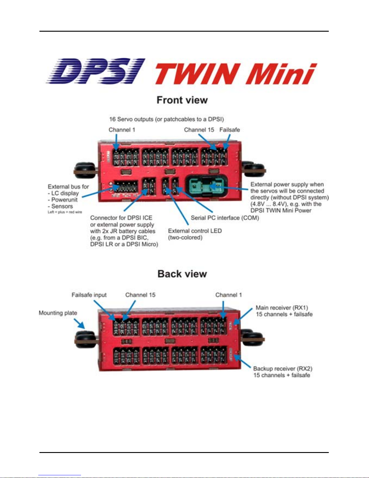
2.3. Connections
Rear View:
You find pin-connectors at the rear for both receivers (or r eceiver and
autopilot). There are 16 connectors each for the “main”-receiver as well
as 16 connectors for the “backup”-receiver or autopilot respectively.
The connectors are JR/UNI compatible.
The 16
th
connector functions as the failsafe-input at the same time
(“FS1” or “FS2”). The failsafe signals of the connected receivers are
evaluated by the DPSI TWIN Mini internall y for switch-over. As long as
the signals value is larger than 75% (percentage of the corresponding
servo channels) the receiver is considered error free. As soon as the
signal drops down to less than 75%, the DPSI TWIN Mini recognizes
an error condition (failsafe) and switches all 16 servo signals to the
error free receiver.
Page 9
DPSI TWIN Mini Operating Instruc tions Version 1.0
Page 9 of 36
If the failsafe pulses are totally missing or are out of specification, this
is recognized as an error condition too. The 75% values are factory set
and can be reprogrammed at any time.
The receivers are connected to the DPSI TWIN Mini using the
accompanying patch cables.
Hint:
Both connected receivers are supplied by the DPSI TWIN MINI via the patch
cables. The battery connectors of the receivers ALWAYS remain unused!
Front View:
You find the pin connectors of the outputs in the upper row
(connections to servo current distribution or to the servos directly).
Page 10

DPSI TWIN Mini Operating Instruc tions Version 1.0
Page 10 of 36
When using a DPSI RV system the patch cables are here connected to
the DPSI. Servos can be directly connected if an optional current
supply is available.
You find in the lower row (from left to right):
AUX1 and AUX2:
here, optional products from the EMCOTEC product
range can be connected (LC display, bridging PCB for th e DPSI power
part, external sensors for RPM, temperature, height, velocity, etc.).
B1 and B2:
connection for the optional DPSI ICE. Furthermore, an
external power supply can be connected, if the DPSI TWIN Mini is to
be used stand-alone (without current distribution), i.e. the servos are
directly connected. For instance, a DPSI BIC, a DPSI LR or a DPSI
Micro can be used as power supply.
EXT:
connection for an optional external bicolor LED, which can be
mounted in the fuselage’s sidewall, providing information about the
current status of the DPSI TWIN Mini (see error indications).
COM:
connection for the RS232 interface cable to a PC (COM
interface) or using an optional USB convert on an USB port of the PC.
Using the PC software, the parameters of the DPSI TWIN Mini can be
programmed and the data logger can be read. Furthermore, new
firmware can be downloaded.
Opt. Bat:
here, an external power supply can be connected if the DPSI
TWIN MINI is being used in the stand-alone version and if the servos
are directly connected. If many servos are to be used, this connection
is to be preferred over the B1 B2 connections. 15A continues current is
possible. The external power supply can be an optional DPSI power
part (contacting a bridging PCB) or a current source ranging from 4.8
volts up to 8.4 volts. Servos and receivers are supplied with this
voltage. Voltages of 5.2 volts up to 6.0 volts are reasonable.
Page 11

DPSI TWIN Mini Operating Instruc tions Version 1.0
Page 11 of 36
Hint:
If an external voltage is supplied to “B1” / “B2” or “opt. Bat”, the DPSI TWIN MINI
must not be connected to a servo current distribution!
3. Properties of the DPSI TWIN Mini
Failsafe operation with automatic switching between two receivers
with up to 16 channels each
Teacher student operation with manual switching between two
receivers using a switching channel on radio
“Pilot-Backup" using two separate frequencies possible (2
transmitters, 2 receivers)
Receiver/autopilot switching for drones
All control functions fully available after switching from one receiver
to the other
Failsafe positions freely programmable
Integrated PC interface for reading and programming of the data
and for software updates of the firmware
Data logger, i.e. important parameter of the last 22 (!) flights are
stored and can be read later by a PC
2 x 16 receiver channels
Integrated bicolor LED’s indicate status of the system
Two failsafe channels for evaluation of receiver function
Cable free system, i.e. all connections are pluggable and therefore
replaceable
Special grounding concept for flawless operation and highest safety
Future-proof concept achieved through extendibility (DPSI ICE,
DPSI LCD, DPSI Power, external sensors etc.)
Each system 100% tested prior to delivery
Page 12

DPSI TWIN Mini Operating Instruc tions Version 1.0
Page 12 of 36
3.1. Data Logger
The integrated data logger (“black box”) stores all relevant operati onal
data of 22 turn-on cycles (flights). Each time, the DPSI TWIN Mini is
turned on, a counter is incremented and the data logger advances one
entry. All data of the last 22 flights remain stored and a possible crash
can be analyzed even after some time (or after several turning on
cycles). Usually, one tests the radio right after a crash. This means, the
set is turned on and off several times, before the data is read off o f the
data logger at home using the PC.
Due to a turn-on counter, the number of cycles is known (since
purchase of the DPSI TWIN Mini). This provides for the real number of
flights of a model.
Page 13

DPSI TWIN Mini Operating Instruc tions Version 1.0
Page 13 of 36
The following data is stored by the data logger:
System-Information:
- Operating Mode (Failsafe or Teaching)
Receiver-Status:
- Number of errors for each receiver (pulse gap greater than
40ms => total malfunction of the receiver)
- Number of errors for each receiver (failsafe, pulse gap
smaller than 10ms, pulse width < 0.8ms, pulse width > 2.2ms
(failsafe only for PCM))
- Time in seconds, where both receivers were in an error condition
simultaneously
The data can provide for exposure of an eventual crash. It is recorded,
if both receivers are failing SIMULTANEOUSLY for e.g. 5 seconds.
This probably causes a model to crash.
3.2. Functional Principal of the Switching
Because two separate receivers are used with the DPSI TWIN Mini, it
must be able to recognize the necessity to switch from the first receiver
(“main”) to the second receiver (“backup”).
This happens based on any receiver output. This output is named
“failsafe output” in this document. For most PCM receivers (Graupner
JR PCM/SPCM as well as Futaba PCM1024), channels 1 through 8
are failsafe capable. Usually, channel 8 is used. Sets from Multiplex do
not use PCM, but rather call it the IPD function. Here too, each IPD
capable channel can be used for failsafe. But even non PCM/IPD
systems can be used with the DPSI TWIN Mini because a total
qualification of the signals takes place and not just only the evaluation
of the failsafe threshold alone.
Page 14

DPSI TWIN Mini Operating Instruc tions Version 1.0
Page 14 of 36
The failsafe outputs of both receivers connected to the DPSI TWIN
Mini are constantly monitored for thei r signal quality. If an e rror occ urs,
this error is qualified after a certain time. A single “one off” does not
lead to switching from one receiver to the other.
For better appreciation, it is helpful to understand how the signals are
provided by the receivers. Most of the remote controls on the market
as of today provide the servos a pulse length coded signal. All approx.
20ms (this is 50 times a second), the receiver sends a pulse to the
servo. Depending on the desired position of the servo, the pulse length
varies between 0.9ms and 2.1ms. In the center position, the pulse
length is 1.5ms, for end positions 0.9ms or 2.1ms respectively. The
DPSI TWIN Mini receives these pulses via the failsafe channels and
evaluates them. The following events are recognized as errors:
Error qualification in DPSI TWIN Mini qualification time
Pulse width is smaller than 0.8ms (100ms)
Pulse width is greater than 2.2ms (100ms)
Pulse gap is smaller than 10ms (100ms)
Pulse gap is greater than 40ms (400ms)
Pulse exceeded failsafe threshold (100ms)
In brackets: error qualification time, i.e. time, after which switching
takes places.
This shows, that also non-PCM-systems can be used, because not
only a certain programmed position (failsafe position) causes a switch
between the two receivers, but also an erroneous signal. If e.g. a
receiver totally fails, it doesn’t provide a signal on its outputs anymore.
The pulse gaps would be greater than 40ms. This is recognized and
switched to the other receiver after a qualification time of 400ms (if t his
one works error free).
Page 15

DPSI TWIN Mini Operating Instruc tions Version 1.0
Page 15 of 36
If the receiver provides for totally wrong signals (e.g. pulse length
greater than 2.2ms), this is also recognized and causes a switch over.
Switching only occurs, if the second (backup) receiver works error free.
If an error exists in the second receiver as well, no switching occurs.
Hint:
Due to a special algorism, it is impossible that switching occurs rapidly inbetween short intervals (which could lead to signal corruption). Each active
receiver remains active for a minimum period of time before switching can occur
(hysteresis).
Hint:
If switching occurred to the second receiver, this receiver remains active, even if
the first one should become error free.
Hint:
Due to the design of the hardware it is assured, that the servos are NEVER
supplied by both or none receiver. Only ONE receiver is connected to the servos
at any point of time.
Hint:
In order to test switching of the receivers the corresponding failsafe connector
can be pulled out from the DPSI.
If uncertain about the failsafe programming of the transmitter, you can connect a
servo in parallel to the failsafe signal. Now you can monitor the correct
adjustments immediately.
Page 16

DPSI TWIN Mini Operating Instruc tions Version 1.0
Page 16 of 36
4. Packing Contents
Content of delivery of the DPSI TWIN Mini
DPSI TWIN Mini base device
20 pieces receiver connection cables (17cm long)
(patch cables with servo connectors on both sides)
=> additional cables available in e-shop
Operating instructions (instructions in English language as
PDF for download from RC-Electronic Homepage)
EMCOTEC adhesive label
5. Mounting Details
5.1. Mounting of the DPSI TWIN Mini
Mounting on 4 silicon hoses has proofed to be the best technical
method. Mount the total packet onto 4 stilts in a shock absorbing
manner.
Mounting using 4pcs. M4 screws with pieces of fuel hoses:
Page 17

DPSI TWIN Mini Operating Instruc tions Version 1.0
Page 17 of 36
In general, always watch for vibration free mounting. Vibration damping
is especially important for the receivers, because they are much more
sensitive to mechanically vibrations than the DPSI TWIN Mini.
Holes spacing for mounting:
5.2. Connecting the Receiver
Although the DPSI TWIN Mini provides especially for connecting two
receivers, operation with one receiver (main) is possible. In this case,
the channel connections of the backup receiver will remain unused.
The DPSI TWIN Mini indicates an error for receiver two (backup
receiver) and will show this failure with the build-in LED in this case.
The actual purpose of the device is to connect two receivers. Because
the DPSI TWIN Mini can handle 16 channels, receivers with up to 16
channels can be connected. The failsafe channel is also “fed through”
and therefore is also available for additional functions.
Page 18

DPSI TWIN Mini Operating Instruc tions Version 1.0
Page 18 of 36
Of course, not all inputs of the DPSI TWIN Mini must be used. If only 5
channels are needed, 5 patch cables suffice for connecting the DPSI
TWIN Mini to the corresponding receiver (plus failsafe channel).
Hint:
When connecting a second (backup) receiver, all servo outputs must be identical
to the first (main) receiver. This means, no servo outputs must be swapped.
BOTH failsafe inputs of the DPSI TWIN Mini must always be connected, because
error recognition of the corresponding receiver takes place here.
Hint:
If the DPSI TWIN Mini is used in conjunction with an autopilot, the autopilot is
connected instead of the backup receiver. Servo connections must be identical to
the main receiver’s assignment.
5.3. Arranging the Antennas
When defining the positions of the antennas, make sure not to mount
the antennas in parallel. Best is a rod aerial for the mail receiver. Guide
the antenna first in parallel to the fuselage from the receiver, than in
90° to the rod aerial. Don’t change the total length of the antenna. If the
rod aerial is 20 cm / 8”, shorten the receiver’s antenna wire by 20 cm /
8”.
The antenna of the second receiver can either be wired to the elevator,
wired inside the wing (not recommendable due to the plug-in-tube) or
also ending in a rod aerial (eventually down wards). The distance
between the antennas should be as large as possible.
Page 19

DPSI TWIN Mini Operating Instruc tions Version 1.0
Page 19 of 36
5.4. Current Supply and Servo Connections
There are several ways to provide power to the equipment. This
depends on connecting the servos directly to the DPSI TWIN Mini or if
the DPSI TWIN Mini is to be used in conjunction with a current
distribution unit (e.g. a DPSI RV).
The most reasonable solution is to use a current distributor (e.g. DPSI
RV Mini 5 or Mini 6, DPSI RV, DPSI 2001 RV or other vendor’s
products).
Page 20

DPSI TWIN Mini Operating Instruc tions Version 1.0
Page 20 of 36
DPSI TWIN Mini in connection with DPSI RV Mini 5:
In this example, the DPSI RV Mini is used as a current distributor. The
DPSI TWIN Mini serves just as receiver switch and is supplied with
voltage by the DPSI RV Mini 5 via the patch cables. Both receivers are
supplied from the DPSI TWIN Mini via their patch cables.
Page 21

DPSI TWIN Mini Operating Instruc tions Version 1.0
Page 21 of 36
DPSI TWIN Mini in connection with DPSI 2001 RV:
Here too, the DPSI TWIN Mini serves as pure receiver switch and is
fully supplied by the DPSI 2001 RV’s patch cables. The DPSI 2001 RV
distributes 10 receiver-outputs to 26 servos. The SPCM receivers in
this example have 10 channels.
Channels 1 through 7 are connected to the corresponding channels of
the DPSI TWIN Mini. Channels 8 (failsafe capable!) of the receivers
are plugged into the failsafe inputs of the DPSI TWIN Mini. Connect
the failsafe output of the DPSI TWIN Mini to channel 8 of the DPSI
2001. It is (partially) available as servo output, too.
Channels 9 and 10 are therefore connected to inputs 9 and 10 of the
DPSI 2001 RV respectively.
Page 22

DPSI TWIN Mini Operating Instruc tions Version 1.0
Page 22 of 36
DPSI TWIN Mini in connection with DPSI RV:
The DPSI RV serves also as current source for the DPSI TWIN Mini
and both receivers. Because the DPSI RV provides 12 inputs,
receivers with 12 channels can be utilized (e.g. Futaba G3).
Page 23

DPSI TWIN Mini Operating Instruc tions Version 1.0
Page 23 of 36
DPSI TWIN Mini in connection with DPSI RV Mini 6 and additional ser v os:
If, in the case of using a DPSI RV Mini 5 (or Mini 6) in combination with
a DPSI TWIN Mini, 8 (or 7) servo connections of t he DPSI RV Mini ar e
not sufficient, additional servos can be connected directly to the DPSI
TWIN Mini.
In this example, all 10 receiver channels are used. 6 channels lead to
the DPSI RV Mini 6, which controls 7 servos (the most loaded servos,
like elevator, aileron, rudder, etc.). Additional 3 servos (e.g. throttle,
choke and landing gear) are directly connected to the DPSI TWIN
Mini. Now, 9 channels are fully usable, the 10
th
channel serves as
failsafe connection.
Page 24

DPSI TWIN Mini Operating Instruc tions Version 1.0
Page 24 of 36
DPSI TWIN Mini with direct connection of servos and external power supply:
In this example, the DPSI TWIN Mini is used in the stand-alone
version, i.e. without current distribution. The supply is realized via the
optional battery connector (MPX connection cable). Current source can
be e.g. a DPSI LR, DPSI BIC or a DPSI Micro. A direct connection of a
5-cell NiMH battery is possible (or any other current source with 4.8
volts up to 8.4 volts).
Page 25

DPSI TWIN Mini Operating Instruc tions Version 1.0
Page 25 of 36
5.5. Failsafe Channel
The failsafe channel (channel “FS1” or “FS2” of the DPSI TWIN Mini)
is also switched when changing to the error free receiver. Therefore, it
can also be used partially as remotely controlled channel.
If settings in the DPSI TWIN Mini are not reprogrammed, a receiver
will be recognized as error free, if the failsafe signal is greater than
1.8ms (+75% servo movement). The receiver is considered erroneous,
if the failsafe signal is lower than 1.2ms (-75% servo movement). The
range in-between is considered as “grey area”.
A receiver switch over therefore only occurs, if the failsafe signal is less
than 1.2ms (-75% servo movement). The failsafe position on the
transmitter therefore must be smaller than -75% (e.g. -80% or -100%).
The range between -75% and +75% is freely usable, because no
switching occurs here. If the failsafe channel is used, the servo must
only be operated in range from -75% up to +150%. It must be made
sure, that the servo path is not mechanically limited when reaching the
failsafe threshold.
6. Beginning of Operation
After turning on, the DPSI TWIN Mini passes the following phases (5
seconds duration):
Advancing the data logger entry and incrementing the turn-on counter
Polling the COM interface whether a PC communication is desired
(diagnosis mode or firmware update)
After a successful self-test, the DPSI TWIN Mini changes into normal
mode after 5 seconds. The built-in LED’s indicate the current status,
i.e. the “Main”-LED turns to green (see error indications). From now on,
the COM interface is inactive.
Page 26

DPSI TWIN Mini Operating Instruc tions Version 1.0
Page 26 of 36
7. Error Indications
There are two indicator LED’s built into the DPSI TWIN Mini (“Main”receiver and “Backup”-receiver). They are bicolor LED’s, which can
shine green as well as red (or mixed as kind of yellow).
In case of errors, the error indication is repeated approximately every
12 seconds. The integrated LED’s indicate the current status of the
DPSI TWIN Mini as follows:
System State LED “Main“ LED “Backup“
Main-receiver active green --Backup- receiver active --- green
Error in Main- receiver
(e.g. failsafe)
red LED blinks:
1x = 1 error
2x = 2 errors
9x = 9 errors
constantly =
more than 9
errors
Example: 5x
blinking means
“5 receiver
errors occurred“
green
Error in Backup- receiver
(e.g. failsafe)
green red LED blinks:
1x = 1 error
2x = 2 errors
9x = 9 errors
constantly =
more than 9
errors
PC communication red red
firmware update Quick alternating blinking red/green
Always, the receiver whose green LED is lit, is “active”, i.e. the
receiver’s servo signals are wired to the servo connectors (as well as
the failsafe channel!).
Page 27

DPSI TWIN Mini Operating Instruc tions Version 1.0
Page 27 of 36
Hint:
The error indication of the ”Main”-receiver only occurs in “failsafe”-mode. In
“teaching”-mode (teacher/student operation) switching between receivers is
desired, therefore no error is indicated from the „Main“-receiver. The “Backup”(or student-receiver) can indicate errors if the failsafe signal indicates
corresponding values.
In order to indicate errors, optional external indicators are available:
the “DPSI ICE” (Information CEnter of DPSI TWIN), the “DPSI LCD” (3line LC-Display with 3 buttons for changing display) as well as a bicolor
LED, which can be mounted at the fuselages sidewall. Displaying
capabilities of “DPSI ICE” and “DPSI LCD” are available from the
corresponding operating instructions.
Error indications of the optional external LED:
State of LED State of System
green System is turned on (Power-On)
red 1x blinking The Main-receiver was or is erroneous
red 2x blinking The Backup-receiver was or is erroneous
red 15x blinking
(fast blinks)
Supply voltage of the DPSI TWIN Mini is less than
4.8V. This is a critical range!
All of these errors are indicated until the power is turned off. Error
output is repeated every 12 seconds. In case of multiple errors, these
are output sequentially.
8. Programming
In order to adapt the DPSI TWIN Mini to desired requirements, all
relevant parameters can be programmed. The programming is non
volatile, i.e. programmed values remain in memory even after turning
the device off until eventual reprogramming occurs. Programming is
accomplished using an external PC via the COM interface of the DPSI
TWIN Mini.
Page 28

DPSI TWIN Mini Operating Instruc tions Version 1.0
Page 28 of 36
Programming using the PC:
You need the TWIN_MINI_ADMIN.EXE software. This program runs
under the Windows operating system and can be downloaded from
www.rc-electronic.com
or from http://shop.rc-electronic.com with no
charge. The program is self explanatory and has h elp-texts in Germ an,
English and French.
Hint:
The connection cable for the serial interface of the PC is not included in the
delivery and must therefore be ordered separately.
When delivered, the DPSI TWIN Mini is programmed in Failsafe-Mode.
A correct receiver is recognized, if the failsafe-pulse is ≥ 1.8ms (greater
than approx. +75% servo path), where as an erroneous receiver is
recognized if the failsafe-signal is ≤1.2 ms (less than approx. -75%
servo path).
Operating mode and pass/fail values can be changed using the PC
software.
The following explanations apply:
In failsafe mode, a signal reaching the failsafe value causes a switch to
the other receiver. Because this switch happens undesired (caused by
a disturbance of the receiver) an error is indicated (by LED).
In teaching mode, the switching is desired (if the “teacher” s witches to
or from the “student”). This switch is not indicated by an error.
For this reason, the DPSI TWIN Mini must be told, which operating
mode it is in.
Page 29

DPSI TWIN Mini Operating Instruc tions Version 1.0
Page 29 of 36
Hint:
In order to allow for correct switching in failsafe operation, the corresponding
channel (failsafe) in the transmitter (e.g. from Graupner JR) or at the receiver
(e.g. from Multiplex) must be programmed to failsafe of course (not in hold
mode)! Please see the operating instructions of your remote control.
Hint:
For programming of the pass/fail settings (or teacher/student settings), a switch
should be installed in the transmitter for this task in advance.
If channel 8 is to be used as the failsafe channel, a switch (preferably a switch,
which can not accidentally be toggled) in the transmitter must be programmed
such, that a servo at receiver output 8 has a position greater +75% in the “pass”
or “teacher” switch position and a position of less than -75% in switch position
“fail” or “student”. You can verify that easily in the transmitter’s menu “servo
position”.
When programming the values for the DPSI TWIN Mini using the PC software,
just bring the transmitters switch to the pass position. Then confirm the value.
Now bring the switch into the other (fail) position programming the fail value.
8.1. Firmware-Update
The built-in micro controller allows for loading new software versions
into the DPSI TWIN Mini (“Firmware-Update“). Here, a program named
TWIN_MINI_FLASH.EXE is to be used (available on the homepage for
download as well). Select the COM port first after starting the program.
In order to establish a connection to the DPSI TWIN Mini, the connect
symbol must be clicked within 5 seconds. Afterwards, the DPSI TWIN
Mini locks out PC communication.
Page 30

DPSI TWIN Mini Operating Instruc tions Version 1.0
Page 30 of 36
After a successful connection, the button “Get Hex File” appears. After
clicking, the Windows Explorer opens. Here, select the previously (from
the homepage) loaded firmware file with the “.hex” extension. If this file
is loaded, the “flash” button can be clicked.
Now, flashing starts (first deletion, then programming, then
verification). This event lasts about 3 minutes. Under no circumstances
remove power from the DPSI TWIN Mini during this time!
Hint:
The supply voltage must not be removed from the DPSI TWIN Mini during
flashing (firmware update) in any circumstances! This leads to data loss, which
can not be rolled back. If this happens, the device must be sent in to EMCOTEC.
9. Application Examples
Teacher/Student operation or Autopilot operation
Task:
The DPSI TWIN Mini is to be used as a teacher/student system. Here,
2 transmitters and 2 receivers equipped with different channels are
utilized. When using a drone control, only one transmitter and one
receiver as well as the autopilot system are used.
Procedure:
Define a free output on the teachers transmitter (e.g. servo output or
actuator 9) for switching from the teacher’s transmitter to the student’s
transmitter. Assign a free mixer to actuator 9. Both switching positions
of the switch are programmed in the transmitter according to the values
for the teacher (e.g. +100%) or student (e.g. -100%). Both positions
are to be verified by using the servo position display of the transmitter.
Page 31

DPSI TWIN Mini Operating Instruc tions Version 1.0
Page 31 of 36
Hint:
In teacher/student mode (or pilot backup) the receivers must have the
corresponding crystal which fits the transmitter’s channel. The student’s
transmitter (backup transmitter) must be programmed with the same model
parameters as the teacher’s transmitter, i.e. all servo-, mixer- and trim- settings.
Please verify all functions on ground IN ADVANCE!
Failsafe-System with Graupner MC24 (receiver PCM)
Task:
A MC24 transmitter with two SMC20 receivers with the same channel
is to be used.
Procedure:
Define a free output for failsafe switching on the transmitter (e.g. servo
output or actuator 8). Assign a switch to actuator 8 using a free mixer.
Both switching positions of the switch are programmed for pass (e.g.
+100%) and fail (e.g. -100%) corresponding to their values
respectively. Verify both positions using the servo position display of
the transmitter. Change channel 8 in the transmitter using menu
“failsafe settings” from “Halt” to “Pos”. Toggle the switch to the failsafe
position and store the value using “STO”.
You find additional instructions about failsafe programming in the
operating manuals of the corresponding manufacturers.
Hint:
For most radios, only channels 1 through 8 are capable of indicating failsafe in
PCM mode. This means, one of these channels is to be selected for switching
failsafe.
Hint:
In order to test the failsafe settings, it is reasonable to connect an additional
servo to the failsafe output of the receiver (“Main“ and/or “Backup“), e.g. using a
V-cable. According to the servo position, you can immediately see, based on the
position of the servo, whether the receiver outputs the correct failsafe signal in
case of a failsafe (turn off transmitter or dual channel assignment).
Page 32

DPSI TWIN Mini Operating Instruc tions Version 1.0
Page 32 of 36
Hint:
The easiest way to test switching between the receivers is to pull off the failsafe
patch cable from the failsafe pin connector of the DPSI TWIN Mini.
10. Safety Instructions
In general, all connecting lines should be run so that they do not
come into contact with moving or hot parts of the model (such as
servos, gears or mufflers).
The DPSI TWIN MINI must be protected from humidity and
moisture.
The DPSI TWIN MINI must be located at a sufficient distance
from neighboring surfaces to enable good heat dissipation of the
cooling element in case of using the optional power supply unit.
Improper handling of the DPSI TWIN MINI can result in serious
damage/injury to property or persons!
Carry out a general inspection of all connections in your model
before each use! All plugs must be correctly polarized and have
clean contacts (i.e. fit tightly). Loose cables present a potential
hazard!
Under no circumstances may power sources that do not meet the
specified voltages be used.
The current-conducting contacts of the connector plugs may not
be short-circuited. If you fail to observe this warning, the shortcircuited cables may overheat and even melt.
The DPSI TWIN MINI may not be taken apart or technically
altered under any circumstances.
Never use the DPSI TWIN MINI for purposes other than for RC
model making as a hobby. Above all, their use in passengercarrying equipment is strictly prohibited.
Operate the DPSI TWIN MINI only with the remote control
components provided for model making.
Page 33

DPSI TWIN Mini Operating Instruc tions Version 1.0
Page 33 of 36
Always ensure that you have fully charged batteries when
operating your model. Empty batteries inevitably lead to failure of
the RC components, which cause the model to crash.
Do not expose the DPSI TWIN MINI to any extremely hot or
extremely cold temperatures, moisture or humidity. This would
lead to danger of malfunction, damage or decreased efficiency.
11. Technical Data of the DPSI TWIN Mini
Supply Voltage 4.8V … 8.4V
Nominal Input Voltage 5.2V ... 7.4V
Quiescent Current (when “On”) ca. 15 mA total (without external wiring)
Max. continuous current using
“opt. Bat.“
25A
Max. continuous current using
“B1“ and “B2“
8A
Number of Receivers 2 receiver with 16 channels each incl. failsafe-channel
Servo Pulse Width
(nominal values)
0.8ms …. 2.2ms
Servo Pulse Width (error
recognition)
< 0.8 ms or > 2.2ms or
pulse spacing < 10ms or distance > 40ms
Number of Servos 16 servo outputs
Interface (Data) RS232 compatible (optional USB adapter available)
CE-Test according to 2004/108/EC
Environmental Conditions -10°C / 14°F... +50°C / 122°F (operating)
Permissible Temperature Range -25°C / 77°F.... +85°C / 185°F (storage)
Filtering (EMI) for 16 servo outputs
Dimensions incl. Flanges 88mm x 60mm x 28mm (L x W x H)
3.46” x 2.36” x 1.10” (L x W x H)
Screw Size for Mounting 4 x 4.2mm / 0.16” for M4 screws
Hole Spacing for Mounting 77.6mm / 3.06” x 48.2mm / 1.9”
Weight 82 grams / 0.18 lb
Warranty 24 month
Technical modifications and errors excepted!
Page 34

DPSI TWIN Mini Operating Instruc tions Version 1.0
Page 34 of 36
12. Warranty
EMCOTEC GmbH shall issue a 24 month warranty on the DPSI TWIN
MINI. The guarantee period shall begin with delivery of the equipment
by the retailer and shall be not extended by any guarantee repair or
guarantee replacement.
During the period of guarantee, the warranty shall cover the repair or
replacement of any proven manufacturing or material defects at no
charge. There shall be no specific entitlement to repair work. In case of
a guarantee claim, the manufacturer shall reserve the right to
exchange the equipment for a product of equal value if repair of the
item is not feasible for economic reasons. There shall be no
assumption of liability for consequential damages that are brought
about by a proven defect during operation of the DPSI TWIN MINI.
There shall be no extended claims for damages.
All transportation, packaging and travel expenses shall be borne
by the purchaser.
No liability shall be assumed for any damages during transport.
If repair is needed, the equipment must be sent to the appropriate
service center of the respective country or directly to EMCOTEC
GmbH.
The guarantee shall only be valid when the following conditions
are met:
The guarantee document (original invoice) must include the
delivery date, the company stamp, the serial number and
signature of the retailer.
No intervention in the equipment may have been undertaken.
It must have been operated in accordance with our operating
instructions.
Only the power sources and other accessory devices and
components that were recommended by us may have been used.
Page 35

DPSI TWIN Mini Operating Instruc tions Version 1.0
Page 35 of 36
The guarantee document, the original invoice and other pertinen t
information regarding the malfunction (a short description of the
defect) must be included with the transmittal.
The equipment must still be the property of the initial purchaser.
If equipment is sent in that later proves to be functional following
an initial inspection, we shall impose a flat processing fee of € 15.
In all other respects, the general business terms a nd conditions of
EMCOTEC embedded controller technologies GmbH shall apply
for any items not listed.
(P) Version 1.0 from September, 26 2007 Robert Hussmann
Page 36

DPSI TWIN Mini Operating Instruc tions Version 1.0
Page 36 of 36
Legal information:
Trademarks:
The following names are registered trademarks:
- EMCOTEC
- DPSI
- DPSI RV
Other product names mentioned in this manual may also be trademarks or registered
trademarks of their respective owners.
Copyright info rmation:
This manual is copyrighted by EMCOTEC GmbH. All rights reserved. This document may not
be copied either entirely or in part, nor may it be transferred to any type of medium or
translated into any other language without the express written approval of EMCOTEC GmbH.
Manual Note:
EMCOTEC GmbH reserves the right make changes to this manual and to equipment
described herein without notice. Considerable effort has been made to ensure that this manual
is free of errors and omissions. We shall n ot assume responsib ility or liability f or any errors th at
may be contained in this manual nor for any incidental, concrete or consequential damage that
may arise from the provision of this manual, or the use of this manual in operating the
equipment, or in connection with the performance of the equipment when so operated.
 Loading...