

Emcotec DPSI RV Mini 5, DPSI RV Mini 6, DPSI RV Mini 5 Magic, DPSI RV Mini 6 Magic Operating Instructions Manual
Page 1

Bedienungsanleitung
Page 2

DPSI RV Mini Family Operating Instructions Version 1.0
Contents
1. Preface .............................................................................................4
2. History..............................................................................................5
3. DPSI RV Mini at a glance................................................................ 6
4. Overall layout ................................................................................ 11
5. Characteristics ..............................................................................12
5.1. Dual Current Supply .............................................................. 13
5.2. Electronically Switches..........................................................13
5.3. Detached Voltage Regulators................................................14
5.4. Servo Current Distribution ..................................................... 15
5.5. APP (Advanced Push Pull Servo Pulse Amplification).......... 15
5.6. HFIB (High Frequency Interference Blocking)....................... 16
5.7. Built-in V-Cable......................................................................16
5.8. Servo-Matching ("Magic" option only).................................... 16
6. Error Detection and Indication..................................................... 17
6.1. IVM (Intelligent Voltage Monitoring)....................................... 17
7. Safety Features of DPSI RV Systems..........................................18
8. Contents of Delivery .....................................................................20
9. Mounting Hints and Programming .............................................. 21
9.1. Mounting the DPSI RV Mini................................................... 21
9.2. Hole-Spacing for Mounting....................................................22
9.3. Mounting the Receiver...........................................................22
9.4. Connecting the Switch Actuator............................................. 23
9.5. Connecting the Receiver ....................................................... 27
9.6. Selecting Batteries.................................................................28
9.7. Soldering Battery Sockets ..................................................... 31
9.8. Charging the Batteries........................................................... 32
9.9. Setting the Voltages............................................................... 33
9.10. Programming the Batteries.................................................. 35
9.11. Connecting Servos .............................................................. 38
Page 2 of 54
Page 3

DPSI RV Mini Family Operating Instructions Version 1.0
10. Servo-Matching ...........................................................................39
10.1. Programming .......................................................................40
10.2. Changing Servo Direction....................................................41
10.3. Setting Servo Center ........................................................... 41
10.4. Setting End-Limits................................................................ 42
10.5. Deletion of all Programming ................................................ 43
10.6 Supplemental Hints for MAGIC-Version ...............................43
10.7. Changing the Model............................................................. 44
10.8. Sequence of Programming.................................................. 44
10.9. Limitation of Range Settings................................................44
10.10. Technical Data of Servo-Matching..................................... 45
11. Connecting Optional Products .................................................. 46
12. Operating .....................................................................................46
13. Error Indication ........................................................................... 47
14. Safety Directions.........................................................................50
15. Technical Data of DPSI RV Mini-Systems................................. 52
16. Warranty....................................................................................... 53
Page 3 of 54
Page 4

DPSI RV Mini Family Operating Instructions Version 1.0
1. Preface
With a DPSI RV Mini dual current supply from EMCOTEC you
purchased a high grade, modern and secure product for your remotely
controlled model. We appreciate your trust and assure you that you
made the right choice!
Long lasting experience for years in development and manufacturing of
electronically systems as well as the knowledge of the world’s best
model airplane pilots has influenced the development. All products are
developed by experienced engineers and manufactured at EMCOTEC
GmbH in Germany on our own production line. Extensive optically and
electronically end tests for every system, which leaves our house,
assure that you, our customer acquire an absolute reliable product,
which considerably increases the reliability of your valuable RC-Model.
Of course, the products not only have been tested extensively in the
laboratory, but also went through intensive flight-testing. Extensive
series of tests with especially in house developed data loggers have
been accomplished to measure the real current consumption in model
airplanes. Like done in the automobile industry FMEA (Failure Mode
and Effect Analysis) reduces the possibility of damage and malfunction
on operating errors to a minimum.
Hint:
We kindly ask you to read these operating instructions carefully and to
observe the installation hints. Thus, errors can be avoided in advance.
We are all ears for your wishes and questions. Challenge us!
Bobingen, October 2008
The Staff of EMCOTEC GmbH
Page 4 of 54
Page 5

DPSI RV Mini Family Operating Instructions Version 1.0
2. History
For all times, EMCOTEC was and is the leader in "safe current
supplies" around RC-Models. Novelties and developments were
initiated by EMCOTEC:
• First dual current supply with servo current distribution and
electronically switches (DPSI 2001)
• First and only "genuine" fail-proof switch actuator for current supplies;
no mechanical influences or microcontroller errors can lead to
malfunctions (DPSI pin switch actuator)
• First LiPo capable dual current supply with regulated output voltage
(DPSI RV Mini, DPSI RV)
• First provider of LiPo-Batteries for supplying receivers (LongGo und
LongGo „S“)
• First and only provider who's products output error information
acoustically (e.g. low voltage)
• First dual current supply with integrated receiver-switches worldwide
(DPSI TWIN)
• First remote control system which transmits in two different
frequencies (HF TWIN)
• First LiPo capable dual current supply with LC-Display for indicating
all relevant data (DPSI BIC)
• First electronically fuse with current monitor which shuts off defective
servos causing an overload (DPSI OCP)
• First electronically switches which are actuated contact free using a
magnet instead of any mechanically switching elements (e.g. push
buttons or switches)
• Smallest and most light weight LiPo capable dual current supply of its
class (DPSI Micro – DPSI RV)
• First receiver switch with 16 channels (DPSI TWIN Mini)
• First dual current supply with integrated receiver switch, 16 channels
and LC-Display (DPSI TWIN Maxi)
• First dual current supply with separate supply voltage for receiver,
servos and pulse amplifiers and integrated servo-matching (DPSI RV
Mini 5/6 Magic)
Innovation and Quality – Made in Germany by EMCOTEC!
Page 5 of 54
Page 6

DPSI RV Mini Family Operating Instructions Version 1.0
3. DPSI RV Mini at a glance
The DPSI RV Mini – family consists of four different dual current
supply systems with servo current distribution for models of medium
size which fit all applications:
DPSI Version Receiver-
DPSI RV Mini 5 5 8 3 built in V-cable
DPSI RV Mini 6 6 7 1 built in V-cable
DPSI RV Mini 5
Magic
DPSI RV Mini 6
Magic
channels
5 8 3 built in V-cable with
6 7 1 built in V-cable with
Servo-
connections
Specifics
servo-matching
servo-matching
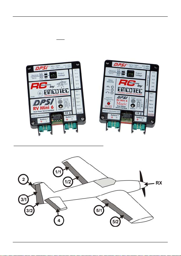
The DPSI RV Mini 5 corresponds to pilots of the 2m to 2.7m air
acrobatic class who need up to 10 servos and where up to 2 servos
actuate one rudder. Therefore, only heavy loaded rudders are supplied
by the DPSI (aileron, elevator and yaw rudder). Servos for additional
functions (e.g. engine, retractable landing gear, etc.) are connected
directly to the receiver.
Page 6 of 54
Page 7
DPSI RV Mini Family Operating Instructions Version 1.0
The DPSI RV Mini 6 is mainly used by jet- and glider-pilots (as well as
engine driven planes and helicopters) were more channels are
necessary but only one
powerful servo actuates one rudder. Here too,
additional (less powered) servos can be directly supplied by the
receiver.
Examples for the DPSI RV Mini 5 (Magic)
An acrobatic airplane with 2 servos per aileron and 2 servos for the yaw rudder. The throttle
servo is directly connected to the receiver.
Page 7 of 54
Page 8
DPSI RV Mini Family Operating Instructions Version 1.0
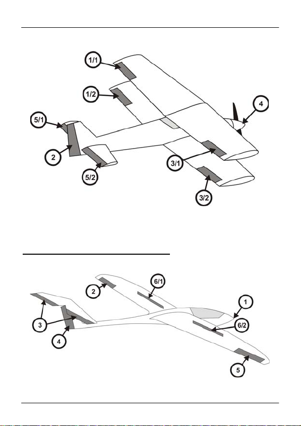
A biplane with 4 aileron servos, split elevator- and one yaw-rudder servo. The throttle servo
may be directly connected to the receiver as an option.
Examples for the DPS RV Mini 6 (Magic)
A glider with spoilers and tow release.
Page 8 of 54
Page 9
DPSI RV Mini Family Operating Instructions Version 1.0
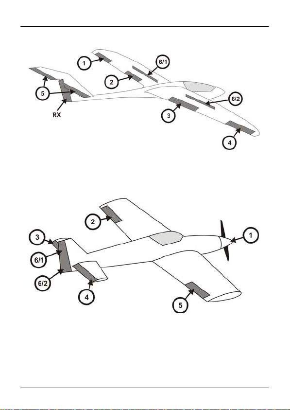
A glider with flaps and spoilers. The yaw rudder (and if so one tow release) are directly
connected to the receiver.
An acrobatic airplane with one servo per rudder, the yaw rudder is actuated by 2 servos.
Page 9 of 54
Page 10
DPSI RV Mini Family Operating Instructions Version 1.0
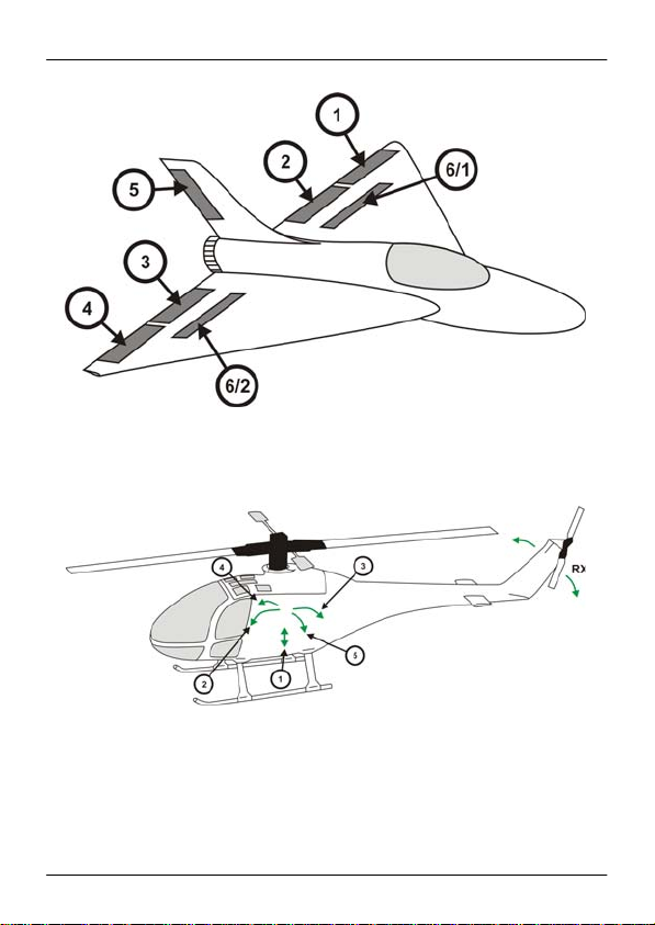
A jet with flaps and spoilers. The turbine-ECU is directly connected to the receiver,
as well as landing gear doors or other electronically systems.
A helicopter with 4-point-control of swash plate (2 roll- und 2 pitch-servos). 1 = throttle. The
gyro (tail rotor) is supplied directly by the receiver (5.2V) or via channel 6/1 of the DPSI (5.9V).
Page 10 of 54
Page 11
DPSI RV Mini Family Operating Instructions Version 1.0
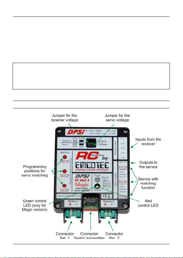
In these examples, the outputs of the DPSI RV Mini are assigned to
the corresponding rudders. Outputs at the DPSI are labeled "Out 1/1",
"Out2", and so on.
Additional servos and auxiliaries can be directly connected to the
receiver.
Hint:
Assignment of the receiver channels to the DPSI is totally arbitrary and therefore
not stringent. Mapping according to the manufacturer (e.g. channel 1 = throttle,
etc.) is not necessary. Receiver channel 3 can be connected to DPSI input 1 just
as well. Any combination is allowed and possible.
4. Overall layout
Page 11 of 54
Page 12

DPSI RV Mini Family Operating Instructions Version 1.0
5. Characteristics
With the DPSI RV Mini - systems a new dimension is reached as far
as safety and comfort about current supplies for RC receiver
equipment is concerned:
Dual current supply (battery switch)
Separate electronically high power switches for both batteries
Up to 50A peak current load
Switching without microcontroller and therefore failsafe (CSHC=
Controller-less Self Holding Circuitry)
Possibility to connect an external LED voltage indicators onto switch
actuator
Due to voltage regulators usage of all battery types available
Selectable output voltage for receiver
Selectable output voltage for servos
Usage of 7.4V servos unlimited
Compliant to all RC receiver-equipment's manufacturers
specifications
Continuously constant servo power due to constant voltage supply
Servo current distribution for heavy loaded servos in system
Optimal recognition and conditioning of servo signals from 2.7V
receivers
Short-circuit proof servo pulse amplifier in current-saving APP-
Technology (Advanced Push Pull) for each individual servo
HFIB (High Frequency Interference Blocking) suppression of induced
HF interference caused by long servo cables (for each individual
servo)
Built-In "V-cable“ for conne cting two servos per channel
Servo-matching for built-in "V-cable“ (in Magic versions)
Failsafe function of programmable servos (in Magic versio ns)
Optically and acoustically warnings on malfunctions, e.g. battery low
voltage or total battery loss
IVM (Intelligent Voltage Monitoring) – intelligent voltage monitoring
with acoustically and optically state indication for six different battery
types (programmable)
Protection of receiver against the so-called "Dynamo Effect“
(feedback of servo counter electromotive force)
Cable free system, i.e. all lines are pluggable and therefore
replaceable at any time
Special grounding concept for flawless operation and highest safety
Page 12 of 54
Page 13

DPSI RV Mini Family Operating Instructions Version 1.0
High grade plastic housing with integrated latches for battery
connectors
Large area heat sink for heat dissipation
Each system 100% tested and provided with individual serial number
Delivery inclusive all accessories
Developed and manufactured by market leader (Made in Germany)
5.1. Dual Current Supply
First of all the DPSI RV Mini is a dual current supply with regulated
output voltage which allows for usage of all commercially available
batteries as a receiver power supply (NiCd, NiMH, LiIon, LiPo, LiFePo,
etc.).
It's a dual current supply because two batteries can be connected to
the system. If one battery fails, secure operation is guaranteed by the
second battery. Normally, both batteries are discharged equally at the
same time. Additionally, current drawn from each battery is cut in half
due to the two batteries connected in "parallel" which allows for
batteries with lower current load capabilities.
5.2. Electronically Switches
The batteries are switched using fail-proof electronically switches. The
external switch actuator only generates the On/Off signal. Power is
switched by highly loadable semiconductors. Thanks to the
electronically switches there is no power loss, contacting problems or
transition resistance. All DPSI RV Mini systems are built with separate
electronically switches, i.e. all electronics are dual. The switches are
fail-proof and are controlled by a self holding circuitry (not by means of
a microcontroller!).
An operating DPSI RV Mini stays turned on even if the On/Off switch
actuator is removed or broken or should the microcontroller
malfunction.
Page 13 of 54
Page 14

DPSI RV Mini Family Operating Instructions Version 1.0
5.3. Detached Voltage Regulators
Until now, the receiver set was supplied directly by the connected
battery (or corresponding battery switch). The output voltage of
batteries depends heavily on the actual discharging state. Because 5cell NiCd or NiMH batteries are utilized more often for optimal servo
power, a fully charged battery reaches voltages up to 7.5V after turning
the charger off. Although this peak voltage usually drops quickly it can
shorten the life cycle of servos in adverse cases because servos
usually are approved only for 6V by the manufacturer. Due to
increased usage of light weight Lithium Polymer batteries voltage
regulation is mandatory because these batteries carry a nominal
voltage of 7.4V.
The electronics in the DPSI RV Mini make sure that the voltage is
reduced to a permissible value, independent of the higher input voltage
of the battery. Jumper (small pluggable bridges) allow for selection of
the desired output voltage. This way, the power requirements can be
adapted to the pilot needs and technical data of the servos.
As a specialty, two separate voltage regulators are built into the DPSI
RV Mini each having its own selectable output voltage. Servos directly
connected to the DPSI are supplied by their own voltage regulator. Its
output voltage is either 5.9V or battery voltage. This means: the servos
are supplied either with a regulated 5.9V (regular permissible voltage)
or directly with the (unregulated) battery voltage. Later is about 7.4V for
2-cell LiPo batteries. Some servos can be supplied with this higher
voltage already.
A receiver connected to the DPSI RV Mini is supplied by its own
voltage regulator. This is very advantageous and gains safety
significantly.
The output voltage of the receiver can be set between 5.2V and 5.9V.
Besides direct connections of high power servos the concept of the
DPSI RV Mini allows for connection of additional low power servos to
the receiver (e.g. a throttle servo), where 5.2V normally suffice.
Page 14 of 54
Page 15

DPSI RV Mini Family Operating Instructions Version 1.0
Even fast tail rotor servos or gyro systems which only "allow for" small
voltages can be supplied by the receiver with 5.2V. Additionally, the
receiver supply is protected against voltage peaks. This means: all
disturbing pulses induced into the supply voltage are limited to safe
values.
5.4. Servo Current Distribution
Furthermore, a DPSI RV Mini provides current distribution for high
power servos, in order not to connect these to the sensitive receiver.
All servos directly connected to the DPSI RV Mini are supplied with full
power and each individual servo gets its maximum possible current.
This can be recognized by a significantly better servo actuating force.
5.5. APP (Advanced Push Pull Servo Pulse Amplification)
In order to provide each servo optimally conditioned control signals
from the receiver, these signals are electronically amplified. This is
especially important if receivers operate on low voltage (e.g. 2.7V);
their pulse amplitude is too low for some servos.
Each individual servo output of the DPSI RV Mini has its own pulse
amplifier and specific HF suppression. The amplifiers recognize even
very weak servo signals from the receiver and elevate the level up to
an exactly defined value. They are short-circuiting proof and are
supplied with their own voltage regulator for safety reasons (i.e. not
with the regular servo voltage). Therefore, the signals always carry a
defined and constant level over the total operating range.
An additional advantage is the current-saving APP-Technology. The
amplifiers consist of special output stages which actively control the
low- as well as the high-phase of the servo signal. In connection with
highly effective filters which practically eliminate induced disturbances
caused by long servo cables completely, best pulse quality and highest
possible safety is guarantied.
Page 15 of 54
Page 16

DPSI RV Mini Family Operating Instructions Version 1.0
5.6. HFIB (High Frequency Interference Blocking)
In order to even increase safety, a highly effective filter is looped in into
each servo's signal path. Disturbances, "caught" by long servo cables
are almost completely eliminated directly at the servo connector and
therefore do not reach the receiver. Ferrite cores, as often utilized, can
be omitted, which saves weight and cost. The filters in the DPSI RV
Mini are tremendously more effective than cheap ferrite cores; their
effectiveness is controversial anyway.
5.7. Built-in V-Cable
Depending on the system (Mini 5 or Mini 6) V-cables are built in to the
DPSI. This means, two servos can be connected to one receiver
output. This is especially handy, if two servos actuate one rudder (e.g.
the aileron of a larger acrobatic plane). The DPSI RV Mini 5 has three,
the Mini 6 one built-in V-cable (e.g. for the yaw
rudder and nose gear).
5.8. Servo-Matching ("Magic" option only)
DPSI RV Mini with "MAGIC" option allow for setting the servos which
are connected to V-cables arbitrarily, i.e. direction, center- and endlimit positions.
This means: one receiver channel serves actually two servos; their
direction, center position and end positions can be aligned. A split
elevator rudder can be controlled by one servo on each side with one
single receiver channel. Therefore one receiver channel and one mixer
in the transmitter get freed up.
The same holds true for controlling the yaw
rudder with coupled nose
gear. Here too, "matching" helps to adapt both servos and saves one
channel.
There is no external programming device (e.g. a PC) necessary for
programming or adapting the servos. A delivered magnet initiates
programming.
Page 16 of 54
Page 17

DPSI RV Mini Family Operating Instructions Version 1.0
Each matching system has its own microcontroller (there are three in
the DPSI RV Mini 5 Magic, one in the DPSI RV Mini 6 Magic).
Resolution (precision) is more than 3000 steps and the delay of the
servo signals is only 1500 micro-seconds!
6. Error Detection and Indication
6.1. IVM (Intelligent Voltage Monitoring)
An internal microcontroller monitors all voltages using an intelligent
algorithm and indicates different errors (overload, low voltage, voltage
errors, battery malfunctions) acoustically by means of a built-in piezobuzzer. Furthermore, errors are visualized by blink codes by a LED in
the switch actuator.
Additionally, the DPSI RV Mini allows for connection of external LED-
Displays (battery monitors) directly at the switch actuator.
In order for the DPSI RV Mini to detect low voltages correctly the
battery type must be programmed once. Simple programming allows
for selection of 6 different battery types.
Page 17 of 54
Page 18

DPSI RV Mini Family Operating Instructions Version 1.0
Hint:
At delivery, low voltage recognition of the DPSI RV Mini systems is programmed
for 2-cell LiPo batteries. If other battery types are to be used, the corresponding
battery type must be programmed in first place (see chapter 9.10.)!
Output voltages for receiver and servos are both set to 5.9 volts at delivery.
7. Safety Features of DPSI RV Systems
Because of the results of FMEA and an elaborate design DPSI RV
Mini is especially safe:
Short-circuits at contacts of the male multi point connector where the
switch actuators cable is connected to, do not damage the DPSI RV
Mini. Therefore even not a defective (squeezed) switch actuator cable.
Shorts on servo pulse lines, no matter whether to ground or positive,
do not any damage, too. All other servos of that channel, where there
is a short-circuit pending, remain fully functional. Even reverse polarity
of a servo does not harm to the DPSI RV Mini.
Mistakenly shorted servo cables usually burn up or melt without
damaging the DPSI RV Mini. The heat sink naturally gets very hot at
events like this!
Both batteries are totally decoupled and also the electronically
switches (inclusive peripheral electronics) are doubled. There are no
dual diodes (two diodes in one housing) built in. Therefore, no
malfunctioning part can cause total fail of the system. This circuitry has
been proven outstandingly several thousand times.
A DPSI RV Mini must not be disconnected from its batteries during
long breaks (e.g. in winter time) because the self discharge of the
batteries is much higher than the quiescent current consumption which
practically is not measurable.
Page 18 of 54
Page 19

DPSI RV Mini Family Operating Instructions Version 1.0
In order to allow for optical power-on control, an ultra bright LED has
been built into the switch actuator of the DPSI RV Mini. It signals
power-on and low voltage or other errors of the battery / batteries by
blinking even over large distances.
All commercially available remote control systems (JR, Futaba,
Multiplex, Spektrum) with all available modulations (PCM, SPCM,
PCM1024, PPM, IPD), 2.4GHz as well, were tested in connection with
DPSI RV Mini systems. Therefore all systems can be utilized with no
problems.
Receivers which are supplied with 2.7 volts internally (e.g. Futaba
6014), can be used without hesitation, because the servo pulses in the
DPSI RV Mini are already recognized at 1.6 volts reliably. Servo
amplifiers in the DPSI RV Mini are supplied by their own voltage which
is totally independent from the regular servo and receiver voltage.
Therefore, voltage peaks and voltage drops do not have any influence
to the pulse quality. Due to its sophisticated safety features in
connection with elaborate testing, operating errors and outside
influences usually do not lead to damage of the DPSI RV Mini.
Page 19 of 54
Page 20

DPSI RV Mini Family Operating Instructions Version 1.0
8. Contents of Delivery
Delivery of DPSI RV Mini 5 (6):
"DPSI RV Mini 5 (6)“ Base Device
On/Off switch actuator with pin and mounting material
5 (6) pieces receiver connection cables (with servo
connectors on both ends => patch cable)
2 pieces MPX high-current sockets for the batteries
4 pieces of shrink tubing for MPX high-current sockets
2 pieces of voltage selection jumpers
Operating instructions, EMCOTEC 3D sticker
Delivery of DPSI RV Mini 5 (6) Magic:
"DPSI RV Mini 5 (6) Magic" Base Device
On/Off switch actuator with pin and mounting material
5 (6) pieces receiver connection cables (with servo
connectors on both ends => patch cable)
Switching-magnet for programming of the matching-functions
2 pieces MPX high-current sockets for the batteries
4 pieces of shrink hoses for MPX high-current sockets
2 pieces of voltage selection jumpers
Operating instructions, EMCOTEC 3D sticker
Each individual DPSI RV Mini system carries its own serial number
and is tested several times prior to delivery!
Page 20 of 54
Page 21

DPSI RV Mini Family Operating Instructions Version 1.0
9. Mounting Hints and Programming
9.1. Mounting the DPSI RV Mini
The DPSI RV Mini is simply mounted onto 4 pieces of silicon hoses
(gasoline hose). Just mount the package vibration damped onto 4
"stilts", as shown in the picture.
In general, always observe vibration free mounting including good air
circulation. Vibration damping is especially important for the receiver
because it is much more sensitive to mechanical stress than the DPSI
RV Mini.
Page 21 of 54
Page 22

DPSI RV Mini Family Operating Instructions Version 1.0
9.2. Hole-Spacing for Mounting
9.3. Mounting the Receiver
The receiver can be directly glued onto the DPSI RV Mini by means of
dual sided adhesive foam rubber (approx. 5-10 mm thick). The
programming marks must remain free for Magic versions.
Separate mounting of the receiver is also possible and even
recommended for 2.4GHz receivers. At high current loads and under
combat conditions, the upper surface of the DPSI RV Mini should
remain uncovered in order to allow for unrestricted heat dissipation.
Hint:
The lower side of the DPSI RV Mini where the heat sink resides, must not be
covered or pasted up with something at all and should have at least a distance of
30mm to the next area (fuselage's bottom or similar)! Good air ventilation
(eventually with air hoods or guided cooling air) is especially reasonable when
operating many servos.
Page 22 of 54
Page 23

DPSI RV Mini Family Operating Instructions Version 1.0
9.4. Connecting the Switch Actuator
Mechanical switches risk malfunctions. There are vibrations at a
fuselage's side wall especially with large models. In order to avoid any
mechanically influence in DPSI RV systems electronically switches
with self-holding circuitry are utilized.
The electronically switches are only controlled by a pulse from the
external switch actuator. The receiving set therefore is turned on or off
by means of a pin or magnet (Magic version). The corresponding
switch actuator just delivers the on/off signal.
Dimensions of the switch transmitters:
Rear side of the switch transmitter with connected battery controllers (optionally)
Page 23 of 54
Page 24

DPSI RV Mini Family Operating Instructions Version 1.0
Pin-Switch-Actuator in DPSI RV Mini:
The pin, put into the "ON" socket (red) turns the DPSI RV Mini on.
Putting it into the "OFF" (black) socket turns the DPSI RV Mini off.
Even if the pin gets lost a powered system remains on.
A DPSI RV Mini only can be turned off if the pin is put into the OFF
socket (in other words swapped from red to black)!
DPSI RV pin-switch-actuator:
Of course, two pins must not be put into each of the sockets at the
same time although this does not damage the DPSI RV Mini. In this
case, the set would be turned off and the batteries would be
discharged slowly with approx. 12mA. In the powered state the pin
should always remain in the ON socket!
Hint:
Should the pin get lost, a 2mm wire or 2mm screw suffices by putting it into the
corresponding socket.
Page 24 of 54
Page 25

DPSI RV Mini Family Operating Instructions Version 1.0
The On/Off switch can be arbitrarily positioned (e.g. at the fuselage's
side wall). Put the connection cable with its plug into the multi point
connector of the DPSI RV Mini until it locks (see picture). If eventually
a swap or disconnect is in order, carefully remove by moving upwards
out of the multi point connector (grapple the cable directly at the plug).
Correctly mounted switch actuator at DPSI RV:
Switch Actuator in Magic versions:
Magic versions of the DPSI RV Mini (with servo-matching) are not
delivered with the pin switch actuator but rather with a magnetically
switch actuator. Because a magnet is necessary for programming the
servo-matching functions it can be used as switching element for the
switch actuator as well.
The magnet is positioned close to the on-position of the switch actuator
(green marking on housing) for about 1 second.
For turning off, hold the magnet close to the opposite marking of the
switch actuator for about 2 seconds.
Hinweis:
For regular DPSI RV Mini versions, a magnetically switch actuator is available as
optional accessory.
Page 25 of 54
Page 26

DPSI RV Mini Family Operating Instructions Version 1.0
DPSI RV magnetically switch-actuator:
The central ultra bright LED in the switch actuator housing is lit when
the DPSI RV Mini is powered. In case of errors (e.g. low voltage) or
during programming, the LED indicates the states by different blink
codes.
Two commercially available battery controllers with JR-Uni connectors
can be connected directly at the rear of the switch actuator. The prints
"B1" and "B2" indicate battery 1 and battery 2 respectively. Herewith,
additional voltage monitoring is possible. When using such voltage
controllers, observe required cell numbers and/or correct battery type.
A turned off DPSI RV Mini system also turns off eventually connected
battery controllers, too.
Page 26 of 54
Page 27

DPSI RV Mini Family Operating Instructions Version 1.0
9.5. Connecting the Receiver
Connect the receiver to the DPSI RV Mini using the delivered patch
cables (see print on housing). When connecting the receiver not all
inputs of the DPSI RV Mini must be used. Just connect as many
cables as needed. Each of the cables provides the receiver with
voltage.
Hint:
All receiver connection cables supply the receiver with regulated output voltage!
Therefore it is not relevant which cable (channel) is connected.
Hint:
At all DPSI RV Mini systems the negative wire (brown) points to top i.e. towards
the print. The pulse wire (orange) points towards the heat sink.
Hint:
If the equipment does not work please make sure that all cables are correctly
connected and that the modulation mode of the transmitter corresponds to that of
the receiver (e.g. PPM, PCM, SPCM, IPD and so on).
Hint:
Assignment of the receiver channels on the DPSI housing's print is only a
suggestion! Assignment is arbitrary in any case. This means: receiver channel 1
must not necessarily be connected to channel 1 of the DPSI. It is only important
that servo outputs correspond to the receiver inputs of the DPSI (e.g. receiver
input 2 to servo output 2). Therefore, receiver channel 1 can be connected to
DPSI input 2. In this case servos at output 2 are controlled by receiver channel 1.
Hint:
Under no circumstances connect a patch-cable between receiver and a servo
output of the DPSI RV Mini. Both, the DPSI RV Mini or the receiver could
become damaged!
Page 27 of 54
Page 28

DPSI RV Mini Family Operating Instructions Version 1.0
9.6. Selecting Batteries
All commercially available batteries are selectable (NiCd and NiMH) as
well as Lithium-Ion (LiIon), Lithium-Polymer (LiPo) or LiFePo (A123).
Independent of the selected output voltage these batteries are usable
with no restrictions.
Page 28 of 54
Page 29

DPSI RV Mini Family Operating Instructions Version 1.0
6-cell NiCd batteries are also connectable. This only makes sense if
the output voltage for the servos is set to "Bat." and servos with a
corresponding higher supply voltage are connected (e.g. 7.4V servos).
Usually 5-cell NiCd/NiMH or 2-cell LiPo batteries are used.
Battery capacities
In general observe current load and capacities of the utilized batteries.
Battery packs of 2 times 450mAh are far too small for a model carrying
10 servos. There should be at least two "2000th" which can be
discharged with 5C (peak current). (C is nominal capacity in Ah => a
battery with 2Ah can be loaded with 5 * 2A = 10A at 5C). Especially
when using digital servos higher current consumption must be
observed.
Our elaborated measurements with a 3m model using 15 digital servos
resulted in a current consumption of about 0.6 – 0.8Ah at 10 minutes
flight time. Dimension your batteries very carefully! If in doubt, ask your
model manufacturer.
Furthermore, make sure, that the connection cables of the battery are
thick enough when selecting the batteries. If a battery with 0.25 mm
2
cable area is being used, the advantage of using the DPSI is lost
because of losses in such thin cables. Therefore, battery wires for
large models should have an area of 1.0 – 1.5mm
2
.
Solder the battery connection cables to the delivered Multiplex high
current connectors to make them compatible to the DPSI RV Mini (if
no readily conditioned batteries are utilized). Shrink tubes for isolating
the solder connections are delivered as well.
If the batteries must be placed far away from the DPSI RV Mini due to
COG (Center of Gravity) purposes (long connection cables) it is
desirable to twist the wires. We recommend using our EMCOTEC
Lithium Polymer batteries. These are delivered completely wired and
can be connected to the DPSI RV Mini right away. An additional
charging connector at the battery allows for charging without removing
the battery from the DPSI. Charging devices for all battery types are
available from EMCOTEC, too.
Page 29 of 54
Page 30

DPSI RV Mini Family Operating Instructions Version 1.0
Selecting the output voltage
Meanwhile almost all servos are suitable for a 5.9V supply voltage.
Therefore, the default setting for servos directly connected to the DPSI
RV Mini is 5.9V. If 7.4V servos are to be used, the output voltage can
be set to battery level ("Bat.") by jumper. In case LiPo batteries are
used servos are supplied with 7.4V.
Some servos are restricted to 4.8V according to manufacturer's
specifications (e.g. fast tail rotor servos for helicopters). Connect these
servos directly to the receiver. Its supply voltage then is set to 5.2V by
jumper at the DPSI RV Mini. 5.2V correspond to the voltage of 4-cell
NiCd batteries which are the reference for 4.8V servos.
As of today, all commercially available receivers can be operated with
5.9V with no limitation. Therefore, the receiver voltage at the DPSI RV
Mini is set to 5.9V by default.
Hint:
The higher the difference between input and output voltage, the higher is the
power dissipation which must be converted to heat. If using many servos it is
advisable to select a higher output voltage at the DPSI RV Mini.
Hint:
Using a 4-cell battery pack (NiCd/NiMH) on a DPSI RV Mini is not permissible!
Page 30 of 54
Page 31

DPSI RV Mini Family Operating Instructions Version 1.0
9.7. Soldering Battery Sockets
Delivered Multiplex high current sockets are marked + and – on their
soldering side. Observing this marking is mandatory! Dismantle the
cable about 5mm, and then tin it. Before soldering, push the delivered
shrink hose over the corresponding cable. Solder the cable to all 3 pins
on one side of the socket; it must contact all 3 pins from the inside (see
picture). If the cables are thin, bend the pins of the socket a little to
their common center. Use plenty of tin to assure good contact to all 3
pins. Shrink the hose using a heat gun.
Soldering Multiplex connectors:
Hint:
DPSI RV Mini systems are not inverse polarity protected by design! Please
observe correct connection of the batteries, i.e. connect red wire to positive and
black wire to negative. Better control once too many than too little!
Page 31 of 54
Page 32

DPSI RV Mini Family Operating Instructions Version 1.0
9.8. Charging the Batteries
All DPSI RV Mini systems switch battery-positive, i.e. both batteries
are interconnected with their negative pole (ground) if connected to a
DPSI. Simultaneously charging therefore is not always possible
because most chargers with more than one charging output measure
the current in their negative line while interconnecting the positive lines.
Separate charging of the batteries is possible at an y time when
connected to a DPSI RV Mini!
If one wishes to charge the batteries while connected to a DPSI RV
Mini a second cable must be soldered to the battery which serves as a
charging cable. This cable then is in parallel to the connection cable of
the DPSI RV Mini.
Simultaneous charging of both connected batteries while connected to
a DPSI RV Mini is only possible with Lithium Polymer batteries. LiPo
batteries may be charged in parallel because the DPSI discharges
these batteries absolutely identically and therefore having identically
discharge states. This means: both batteries are interconnected in
parallel for charging by means of a V-cable (positive to positive,
negative to negative). This makes it a "2S2P“-battery. Cell number
(voltage) stays the same, charging current may be doubled.
Corresponding charging cables are available from EMCOTEC.
If in doubt it is reasonable and safer to disconnect the batteries from
the DPSI RV Mini for charging. Just tilt the plug a little (to the side) and
pull it from its DPSI RV Mini latches with slight zigzag moves.
Hint:
It is possible to charge the battery when still connected to the DPSI RV Mini (e.g.
via an additional soldered charging cable). Only charge one battery at a time
(exception: LiPo batteries). Please observe correct polarity!
Page 32 of 54
Page 33

DPSI RV Mini Family Operating Instructions Version 1.0
Removing the battery plugs from the DPSI RV Mini:
9.9. Setting the Voltages
The output voltage of the DPSI RV Mini can be set in 2 steps for the
receiver as well as the servos. This is done using delivered jumpers
which are plugged to the multi-pin connectors of the DPSI RV Mini
depending on the desired output voltage. Best use a tweezers or small
pliers.
Setting the voltage of the receiver and the servos to 5.9 Volt:
Page 33 of 54
Page 34

DPSI RV Mini Family Operating Instructions Version 1.0
Selecting full battery voltage for the servos (receiver stays at 5.9V):
The positions of the jumpers on their multi-pin connectors and their
corresponding output voltage are printed onto the housing of the DPSI
RV Mini. Because a DPSI RV Mini should be mounted vibration-less
the jumpers can not fall out.
Page 34 of 54
Page 35

DPSI RV Mini Family Operating Instructions Version 1.0
9.10. Programming the Batteries
Because DPSI RV Mini systems monitor the battery voltage
intelligently, they need to know the utilized battery type (e.g. 5-cell or 6cell batteries or LiPo batteries). Therefore the battery type must be
programmed once – the programmed state is memorized in the
microcontroller of the DPSI RV Mini until programmed again.
Programming starts when only one
battery (no matter which type and
at which connector) is connected to the DPSI RV Mini and when the
system is turned on.
After power on, the internal buzzer (signaling device) of the DPSI RV
Mini turns on for 3 seconds and pauses for another 3 seconds. This
indicates operating mode "programming".
Now one beep follows which indicates "battery type no. 1". If the
missing battery is now connected to the DPSI RV Mini within 3
seconds, "battery type no. 1" is selected and programmed.
If the missing battery is not connected within 3 seconds, two beeps
follow for indicating "battery type no. 2". Again, the user has 3 seconds
to connect the missing battery if he/she wishes to select (program) this
battery type.
This principal is repeated until the buzzer beeps seven times
(deactivate all tests). If no battery is connected within 3 seconds there
is no programming at all and the system changes to normal operation.
Page 35 of 54
Page 36

DPSI RV Mini Family Operating Instructions Version 1.0
Battery types are defined as follows:
Type no. Buzzer Code Battery Type / Programming
1 1x beep 5 cells NiCd / NiMH
2 2x beeps 6 cells NiCd / NiMH
3 3x beeps 2 cells Lithium-Ion
4 4x beeps 2 cells Lithium-Polymer
5 5x beeps 2 cells LiFePo (e.g. A123)
6 6x beeps 7 cells NiCd / NiMH (res.)
7 7x beeps All tests deactivated
By default "battery type 4" (LiPo battery) is programmed at delivery.
Selection "7 beeps" (all tests deactivated) causes the DPSI RV Mini
not to conduct any voltage tests. No empty batteries or other errors are
indicated anymore.
Hint:
Always use two identical batteries (i.e. same battery type: NiCd, NiMH or LiPo
and same number of cells). Battery capacity may be different - although it makes
no sense.
Hint:
The battery type is output after powering the DPSI RV Mini on by means of
buzzer codes. Multiple beeps after turning the system on therefore do not
indicate an error!
Page 36 of 54
Page 37

DPSI RV Mini Family Operating Instructions Version 1.0
Programming the battery type at a glance:
Page 37 of 54
Page 38

DPSI RV Mini Family Operating Instructions Version 1.0
9.11. Connecting Servos
The DPSI RV Mini 5 (Magic) distributes 5 receiver channels to 8
servos in total (with 3 "built-in“ V-cables).
The DPSI RV Mini 6 (Magic) distributes 6 receiver channels to 7
servos in total (with 1 "built-in“ V-cable).
In the example at page 28, 8 servos are connected to the DPSI RV
Mini 5 in total, the throttle servo however directly at the receiver. For all
servos connected to the DPSI RV Mini the pulse wire points
downwards (as pretended by chamfered noses in housing). We do not
recommend connecting more than 10 servos in a receiver system
powered with a DPSI RV Mini in total because current limits can be
reached or thermal load could get too high.
Observe sufficient cooling when using digital servos, in any case.
Hint:
Dependent on number and force of servos total current consumption varies in the
system. The higher the total current consumption, the higher is the energy which
is converted to heat. The heat sink of the DPSI RV Mini can get very hot. This is
not an error, but rather represents normal function. Therefore, observe for
sufficient cooling (distance to neighboring walls like fuselage's side walls or
similar – eventually arrange for cooling air supply). On request, an additional heat
sink can be mounted.
Hint:
Printed assignment connections on top of the DPSI RV systems are only a
suggestion! Receiver channels may be connected to any DPSI inputs. Receiver
channel "1" might be connected to DPSI input "3". Servo outputs "3" of the DPSI
are then controlled by receiver channel "1". Assignment therefore is arbitrary!
Page 38 of 54
Page 39
DPSI RV Mini Family Operating Instructions Version 1.0
10. Servo-Matching
This is especially helpful if e.g. two servos actuate one rudder and
synchronized movement is not possible by mechanically adjustments
(e.g. two servos for one aileron). Often it suffices to change one
servo's direction. This is also simply possible with the MAGIC version.
Failsafe-Function:
Additionally a failsafe function has been integrated. An erroneous or
missing receiver signal stops both servos (master and slave) at their
current position (hold) until a valid receiver signal is recognized again.
This state is indicated by a flashing green LED on the upper side of the
housing ("status") which stays active until power is turned off. After the
flight the flashing LED indicates a failsafe situation.
High Precision:
Due to the intelligent software design and a highly accurate crystal
oscillator resolution is more than 3000 steps. Therefore, the system is
suitable even for modern remote controls with high servo positioning
accuracy (number of steps).
There are built-in V-cables in a DPSI RV
Mini allowing two servos to connect to one
receiver channel (Mini 5 has three Vcables; Mini 6 has one V-cable). As a
specialty, MAGIC versions allow to
program the direction, center- and end
positions for one of both servos ("slave"
servo). This servo therefore can be
"matched" to the main servo (MSTR).
Page 39 of 54
Page 40

DPSI RV Mini Family Operating Instructions Version 1.0
10.1. Programming
No external operating unit is necessary for programming the slaveservos such as a PC or a programming box. Only the delivered magnet
serves to activate the corresponding programming function. Everything
else is done with the transmitter (the remote control system).
During programming settings of the original servo (master) do not
change! Programming always refers to the slave servo. The slave
servo connects to the red encircled output. This is the servo at output
"Out 6/2" for the DPSI RV Mini 6 Magic; for the DPSI RV Mini 5
Magic these are outputs "Out 1/2“, "Out 3/2“ and "Out 5/2“.
Hint:
Setting and programming of the slave servo is only possible within the first 10
seconds after powering the DPSI on. Afterwards programming is inhibited for
safety reasons!
Hint:
Prior to EACH programming the corresponding transmitter stick (or switch
actuator) must be positioned in the center!
Hint:
If both servos, MSTR and SLAVE share one rudder at least one link must be
released in order to avoid mechanically blocking of the servos.
Hint:
Whenever the servo center is changed, end-limits should be reprogrammed as
well!
Hint:
Implemented basic settings correspond to servo values of Graupner/JR sets.
Center position is 1.50ms; end-positions are set to 100% each. Of course, all
remote control sets can be utilized.
Page 40 of 54
Page 41

DPSI RV Mini Family Operating Instructions Version 1.0
Hint:
Whenever programming is activated the green LED blinks for controlling
purposes in the DPSI RV Mini Magic at a rate of 0.5Hz (1s on, 1s off). A fast
blinking of this green LED indicates a failure (=> missing receiver signal).
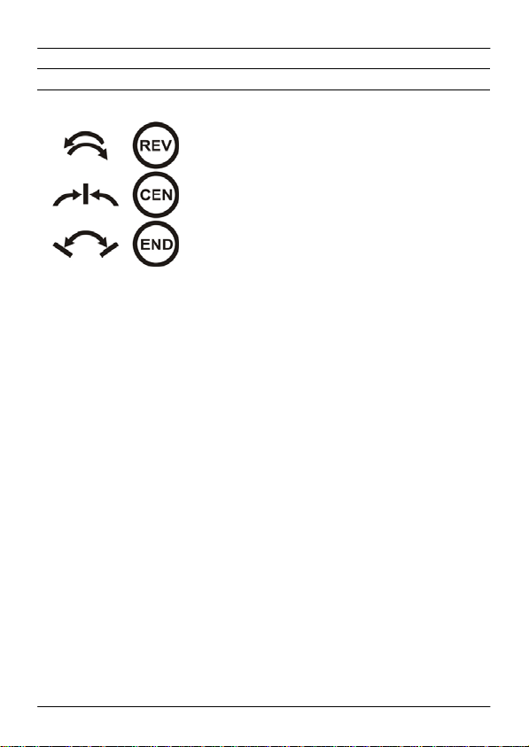
10.2. Changing Servo Direction
programming panel" field) within the first 10 seconds after power on.
Distance of the magnet may be up to 8mm. It is easiest to set the
magnet onto the housings upper surface.
2.5 seconds after placing the magnet the slave servo makes a short
move back and forth (approx. 10% deflection). If the magnet is then
removed within 5 seconds, the direction of the servo changes and is
permanently stored.
current position (on the red dot). The transmitter's stick or switch
actuator must not be moved anymore, i.e. it must remain on its center
position. After another 5 seconds the servo turns again. Now
programming of the servo's center position is activated.
The master servo now remains in its current center position and does
not move even if the transmitter's stick is moved. Each move of the
stick out of its center position increases or decreases the servo
position (servo center) of the slave servo for one step.
If the direction of a servo is to be changed, all
other settings remain! For changing the direction
of the servo, the magnet is to be put close to the
corresponding position (red dot in the "magnetic
10.3. Setting Servo Center
Programming also starts by positioning the
magnet close to the red dot. The servo turns
shortly (just as when changing direction). Do
not remove the magnet now but keep it on the
Page 41 of 54
Page 42

DPSI RV Mini Family Operating Instructions Version 1.0
Holding the stick in its end position the steps increase or decrease
automatically after 2.5 seconds. This serves for quicker settings.
Hint:
Due to the high resolution it is possible that the change in servo positions is only
visible after several single steps.
As soon as the slave servo reaches its final center position remove the
magnet from the red dot. Programming of servo center is finished.
Hint:
If the servo center position is newly programmed, the end-positions should be reprogrammed as well in order to gain linear curves.
10.4. Setting End-Limits
Programming of end limits starts identically to
programming servo center. Here, the stick (or
switch actuator) is put into its maximum end
position within 5 seconds after the servo
makes its short move. After these 5 seconds the servo moves again
and both servos remain in their maximum-position. The stick is now
moved to its center position – servo positions do not change!
Here too, deflection of the slave servo is accomplished by moving the
stick out of its center position in order to increase or decrease the
steps.
Page 42 of 54
Page 43

DPSI RV Mini Family Operating Instructions Version 1.0
If the desired end position is reached, remove the magnet.
Hint:
Whenever changes of servo deflections are programmed, all values should be
reprogrammed, i.e. center position and end-positions! Sequence of programming
(center, end-positions) is actually unimportant.
Caution:
Programmable values for end positions of the servos can be higher than the
mechanically resolution of the servo. The servo therefore could be damaged or
function incorrectly if the full range is being used. Therefore approach limits
carefully. An additionally connected servo tester (e.g. EMCOTEC Mini Servo
Tester – part number A71050) which indicates the corresponding servo position
digitally can be helpful if in doubt.
10.5. Deletion of all Programming
Total reset of all programmed settings is also
possible. Just position the magnet close to the
red dot after powering the DPSI RV Mini on
and keep it there for about 30 seconds. After
2.5 and additional 5 seconds, the servo makes its short move (just like
when programming center / end values). The stick must not be moved
at all during this time and the magnet must remain at its position close
to the red dot. After 30 seconds have elapsed all settings are deleted.
Hint:
Whenever programming is activated the green LED on the DPSIs top side blinks
for controlling purposes in the DPSI RV Mini Magic at a rate of 0.5Hz (1s on, 1s
off).
10.6 Supplemental Hints for MAGIC-Version
These additional hints are valuable for the ambitious user who likes to
know more about the functions of servo-matching by explaining its
behavior under certain circumstances.
Page 43 of 54
Page 44

DPSI RV Mini Family Operating Instructions Version 1.0
10.7. Changing the Model
If an already programmed DPSI RV Mini is to be used in another
application (e.g. changing the model) all settings should be generally
deleted (see "Deleting of all Programming"). This holds true if even a
servo with different direction is built in.
10.8. Sequence of Programming
When programming the slave servo, set direction first (if necessary).
Then center position and end-positions follow, while the sequence is
not important.
Hint:
Whenever a change of e.g. then servo center position is reprogrammed, endpositions should be reprogrammed as well!
10.9. Limitation of Range Settings
The DPSI RV Mini only allows for certain values during programming
of the slave servo. Because the slave servo is to be adapted to the
master servo both servos should have a similar basic setting e.g. a
similar center position.
If the servo center of the master servo already exceeds 100% of the
servo deflection it does not make much sense to offset the slave servo
even further. Therefore only a setting of a servo center for a maximum
of +/-100% is possible.
Setting of the slave servo is generally accomplished by a so called 3point curve (i.e. center position, maximum value left / upper, maximum
value right / lower).
"Distance" of maximum value to the center position is 20% minimum
otherwise the value is not programmable.
Page 44 of 54
Page 45

DPSI RV Mini Family Operating Instructions Version 1.0
A range check takes place at every programming attempt. It is
therefore not possible to position the servo center position outside of
the maximum value. This inhibits malfunctions (e.g. V-curve of servos).
10.10. Technical Data of Servo-Matching
Servo Signal Level Input:
Low-Level 0V ... 0.8V
High-Level 2.0V ... 8.4V
Servo Signal Level Output approx. 5.0V
Permissible Center Position +/-100% (1.10ms .... 1.90ms)
Permissible End-Limits* +/-200% (0.70ms .... 2.30ms)
Permissible Signal Period min. 6.9ms, max. 34.868ms
Resolution (steps) 3200
Page 45 of 54
Page 46

DPSI RV Mini Family Operating Instructions Version 1.0
* Caution:
Programmable values for end positions of the servos can be higher than the
mechanically resolution of the servo. The servo therefore could be damaged or
function incorrectly (e.g. wheel spinning) if the full range is being used. Therefore
approach limits carefully.
11. Connecting Optional Products
Operating the DPSI RV Mini with Gyros
It is possible without any difficulty to operate the DPSI RV Mini in
connection with a gyro. The gyro and its connected servos can be
supplied by the receiver without problems.
Varios, Smoke-Pumps, Retractable Gears and other Consumers
All other types of consumers can be connected to the DPSI RV Mini
just like a normal servo. Using a DPSI RV Mini also allows for
connecting additional auxiliary functions directly at the receiver if the
available slots (channels) of the DPSI RV Mini are not sufficient. Just
observe maximum current (see also technical data).
Ignitions
Even if it appears appealing to supply the ignition system for gasoline
engines by a DPSI we strongly recommend not doing so! Ignitions
induce considerable disturbances which influence the range of the
remote control if integrated into the receiving set. Always supply the
ignition system with a separate battery!
12. Operating
After powering the DPSI RV Mini on, the red ultra bright LED in the
switch actuator and the LED in the DPSI RV Mini illuminate. This
signals operation. Immediately after power on, the signaling device
(buzzer) indicates the programmed battery type (once, twice, three-,
four-, five-, six- or seven times). Afterwards, the algorithm for error
recognition starts.
Page 46 of 54
Page 47

DPSI RV Mini Family Operating Instructions Version 1.0
In case one battery is not connected, the DPSI RV Mini starts in
programming mode. This programming mode automatically ends after
approx. 30 seconds. Within these 30 seconds, the second battery must
not be connected if reprogramming is not desired.
Hint:
If the buzzer beeps 3 seconds after turning the DPSI RV Mini on, only one
battery is connected and the DPSI starts in programming mode. If no
reprogramming is desired, either turn the DPSI RV Mini off or wait approx. 30
seconds before connecting the second battery.
Hint:
If the DPSI RV Mini indicates errors for low voltage after a short period of time
although the batteries are fully charged, probably the wrong battery type is
programmed.
It is also possible, that a battery with a too high internal resistance is used which
breaks down when loaded (e.g. NiMH batteries in AA size). Only utilize batteries
for high current load!
13. Error Indication
There is a microcontroller integrated into the DPSI RV Mini which
constantly monitors all voltages and the function of the voltage
regulator. An intelligent algorithm makes sure that low voltage of a
connected battery not only is detected during shortly dropping voltages
(e.g. in case all servos move at once). The algorism is especially
designed for operating RC-models (this is cyclic load of the batteries)
i.e. not constant load of the batteries. Now, reliable recognition of low
voltages is possible.
Despite this, don't trust blindly low voltage recognition. A good and
responsible model pilot knows how long he/she can fly with fully
charged batteries and recharges them in time (not just when low
voltage is indicated).
Different error types are indicated by the internal piezo-buzzer and the
red LED in the switch actuator.
Page 47 of 54
Page 48

DPSI RV Mini Family Operating Instructions Version 1.0
1. Overload (short circuit):
Error signal: constant beep
⎯⎯⎯⎯⎯⎯⎯⎯⎯⎯⎯⎯⎯⎯⎯⎯⎯
If current consumption of the DPSI RV Mini gets too high a constant
beep is output. In this case, an external short-circuit is detected which
can lead to total damage of the DPSI RV Mini (depending on the
duration of the short). Immediately turn the system off or disconnect
the batteries. This error type has highest priority. If the short (during
operation) gets away, the buzzer stops beeping after a "dequalification" time of approx. 4 seconds.
2. Battery empty: ⎯⎯⎯ ⎯⎯⎯ ⎯⎯⎯ ⎯⎯⎯
Error signal: endless 0.5 seconds beeps / 0.5 seconds
pause
If the voltage at the receiver (not at batteries!) drops below 4.5V, error
type 2 is output. The batteries (no matter which type) are totally
discharged and safe operation not possible any more. This error is
extremely critical because the whole RC-system can drop out of
operation at any time (due to low voltage).
Error type 2 has second highest priority and is active until the DPSI RV
Mini is turned off. If using LiPo-cells, a state is reached where the
batteries are irrevocable destroyed if not turned off immediately and
the batteries being recharged.
3. Voltage Regulator defective:
Error signal: endless 0.5 seconds beep / 0.1
⎯⎯⎯⎯ ⎯ ⎯⎯⎯⎯ ⎯
seconds pause, 0.1 seconds beep
This error signal is output if the voltage regulator for supplying the
receiver malfunctions. Send in the DPSI for repair in this case. Error
type 3 has third highest priority and stays active until turning the DPSI
RV Mini off.
Page 48 of 54
Page 49

DPSI RV Mini Family Operating Instructions Version 1.0
4. Battery Malfunction:
Error signal: endless 0.1 seconds beeps / 0.1 seconds
⎯ ⎯ ⎯ ⎯ ⎯ ⎯ ⎯ ⎯ ⎯
pause
If a battery fails of a DPSI RV Mini (e.g. broken cable, loose contact or
battery defective) a fast buzzer signal is output (5Hz). This error type
has forth highest priority. If the disconnection stops during operation,
the error stays active (until power off)!
5. Low Voltage battery 1:
Error signal: 3 times 0.1 seconds beeps with 0.1
⎯ ⎯ ⎯ ⎯⎯⎯⎯⎯⎯⎯⎯
seconds pause each, then 1 second beep
If the voltage of battery 1 drops a certain level this buzzer code is
output. Usually capacity suffices for one more flight before recharge is
in order. It is better to recharge right away if this error code is indicated.
A correctly programmed battery type of course is prerequisite
(NiCd/NiMH, LiIon, LiPo or LiFePo with corresponding cell number).
This error code repeats every 7 seconds. If this error is qualified the
first time, it stays active until the DPSI RV Mini is turned off.
6. Low Voltage battery 2:
Error signal: 3 times 0.1 seconds beeps with 0.1
⎯ ⎯ ⎯ ⎯⎯⎯⎯⎯ ⎯⎯⎯⎯⎯
seconds pause each, then 2 times 0.65 seconds
beeps with 0.1 seconds pause
If the voltage of battery 2 drops a certain level this buzzer code is
output. Usually capacity suffices for one more flight before recharge is
in order. It is better to recharge right away if this error code is indicated.
A correctly programmed battery type of course is prerequisite
(NiCd/NiMH, LiIon, LiPo or LiFePo with corresponding cell number).
This error code repeats every 7 seconds. If this error is qualified the
first time, it stays active until the DPSI RV Mini is turned off.
If battery 1 as well as battery 2 indicates low voltage, both error codes
are output alternatively. Low voltage errors 5 and 6 have lower priority
(importance) than errors 1-4. In case of an error of type 1.-4., output of
low voltage errors is interrupted.
Page 49 of 54
Page 50

DPSI RV Mini Family Operating Instructions Version 1.0
Hint:
Limits for recognizing low voltage are especially set up for operating RC models.
When utilizing the DPSI RV Mini for other purposes erroneous information could
eventually be output. If this is the case the error indication (if disturbing) can be
completely inhibited (see also "Programming the Battery Type“).
Hint:
Low voltage recognition is only pointing to batteries getting weak and do not
absolve the user from his/her care of only to fly with fully charged batteries! Due
to different characteristics of batteries from different manufacturers low voltage
recognition does not feature 100% safety.
14. Safety Directions
In general, all connecting lines should be run so that they do not
come into contact with moving or hot parts of the model (such as
servos, gears or mufflers).
The DPSI RV Mini must be protected from humidity and moisture.
The DPSI RV Mini must be located at a sufficient distance from
neighboring surfaces to enable good heat dissipation of the
cooling element.
Improper handling of the DPSI RV Mini can result in serious
damage/injury to property or persons!
Carry out a general inspection of all connections in your model
before each use! All plugs must be correctly polarized and have
clean contacts (i.e. fit tightly). Loose cables present a potential
hazard!
Under no circumstances may power sources that do not meet the
specified voltages be used.
The current-conducting contacts of the connector plugs may not
be short-circuited. If you fail to observe this warning, the shortcircuited cables may overheat and even melt.
The DPSI RV Mini may not be taken apart or technically altered
under any circumstances.
Page 50 of 54
Page 51

DPSI RV Mini Family Operating Instructions Version 1.0
Never use the DPSI RV Mini for purposes other than for RC
model making as a hobby. Above all, their use in passengercarrying equipment is strictly prohibited.
Operate the DPSI RV Mini only with the remote control
components provided for model making.
Always ensure that you have fully charged batteries when
operating your model. Empty batteries inevitably lead to failure of
the RC components, which cause the model to crash.
Do not expose the DPSI RV Mini to any extremely hot or
extremely cold temperatures, moisture or humidity. This would
lead to danger of malfunction, damage or decreased efficiency.
Only use EMCOTEC approved accessories in connection with the
DPSI RV Mini (e.g. switch actuator, external voltage monitors,
etc.)
We recommend the usage of EMCOTEC Lithium-Polymer batteries for
the DPSI RV Mini systems. There are several capacities available as
well as chargers, balancers and other accessories.
Page 51 of 54
Page 52

DPSI RV Mini Family Operating Instructions Version 1.0
15. Technical Data of DPSI RV Mini-Systems
Current sources 5, 6, (7)-cell NiCd / NiMH Cells, 2-cell Lithium-Ion
Operating voltage range 5.0V .... 13V
Nominal input voltage 6.0V .... 8.4V
Output voltage receiver 5.2V or 5.9V settable by jumper
Output voltage servos 5.9V or full battery voltage settable by jumper
Quiescent current (turned off) approx. 1µA per battery
Quiescent current (turned on) approx. 55mA totally (MAGIC versions approx. 70mA)
Max. continuous current @ 5.9V
(15 minutes with LiPo batteries)
Max. peak current @ 5.9V
(10 seconds with LiPo batteries)
Drop-out losses @ 4A 0.4V
Maximum power dissipation 8W
Number of servos Up to 10 servos in the complete system
CE approvals according to 2004/108/EC
Environmental conditions -10°C .... +50°C
Permissible temperature range -25°C .... +85°C
LCL filtering (EMI) For each individual servo output
Interference Suppression at
35MHz
Dimensions incl. latches for
battery connections
Screw diameter for mounting 4 x 4.2mm
Hole spacing for mounting 78.7mm x 67.7mm
Weight approx. 105 grams
Warranty 24 month
batteries, Lithium-Polymer batteries, LiFePo batteries
5 Ampère
50 Ampère
-20dB @ 35MHz, -34dB @ 100MHz
77mm x 99mm x 15.8mm
Technical modifications and errors excepted!
(C) EMCOTEC embedded controller technologies GmbH
(P) July 2008 Version 1.0 from 01.October 2008
Robert Hussmann www.emcotec.de
www.rc-electronic.com
Page 52 of 54
Page 53

DPSI RV Mini Family Operating Instructions Version 1.0
16. Warranty
EMCOTEC GmbH shall issue a 24-month warranty on the DPSI RV Mini. The
guarantee period shall begin with delivery of the equipment by the retailer and
shall be not extended by any guarantee repair or guarantee replacement.
During the period of guarantee, the warranty shall cover the repair or
replacement of any proven manufacturing or material defects at no charge. There
shall be no specific entitlement to repair work. In case of a guarantee claim, the
manufacturer shall reserve the right to exchange the equipment for a product of
equal value if repair of the item is not feasible for economic reasons. There shall
be no assumption of liability for consequential damages that are brought about by
a proven defect during operation of the DPSI RV Mini. There shall be no
extended claims for damages.
All transportation, packaging and travel expenses shall be borne by the
purchaser.
No liability shall be assumed for any damages during transport.
If repair is needed, the equipment must be sent to the appropriate service
center of the respective country or directly to EMCOTEC GmbH.
The guarantee shall only be valid when the following conditions are met:
The guarantee document (original invoice) must include the delivery date,
the company stamp, the serial number and signature of the retailer.
No intervention in the equipment may have been undertaken.
It must have been operated in accordance with our operating instructions.
Only the power sources and other accessory devices and components that
were recommended by us may have been used.
The guarantee document, the original invoice and other pertinent
information regarding the malfunction (a short description of the defect)
must be included with the transmittal.
The equipment must still be the property of the initial purchaser.
If equipment is sent in that later proves to be functional following an initial
inspection, we shall impose a flat processing fee of € 15.
In all other respects, the general business terms and conditions of
EMCOTEC embedded controller technologies GmbH shall apply for any
items not listed.
Page 53 of 54
Page 54

DPSI RV Mini Family Operating Instructions Version 1.0
Legal information:
Trademarks:
The following names are registered trademarks:
- EMCOTEC
- DPSI - Dual Power Servo Interface
- DPSI RV
Other product names mentioned in this manual may also be trademarks or registered
trademarks of their respective owners.
Copyright information:
This manual is copyrighted by EMCOTEC GmbH. All rights reserved. This document may not
be copied either entirely or in part, nor may it be transferred to any type of medium or
translated into any other language without the express written approval of EMCOTEC GmbH.
Manual Note:
EMCOTEC GmbH reserves the right make changes to this manual and to equipment
described herein without notice. Considerable effort has been made to ensure that this manual
is free of errors and omissions. We shall not assume responsibility or liability for any errors th at
may be contained in this manual nor for any incidental, concrete or consequential damage that
may arise from the provision of this manual, or the use of this manual in operating the
equipment, or in connection with the performance of the equipment when so operated.
Page 54 of 54
 Loading...