

Page 1
333333333
System 5000
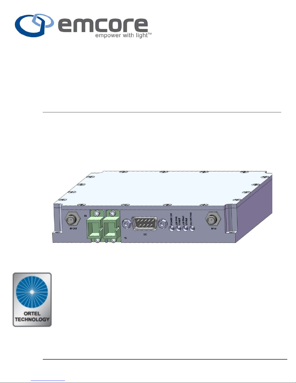
5021TR Wideband Transceiver Link
Installation Manual
Copyright © 2008 Emcore Corporation MAN-5021TR, Rev B
Page 2

Emcore Corporation
System 5000 series
Table of Contents
General................................................................................................................................................2
Interface....................................................................................................................................................4
Installation......................................................................................................................................5
Operation..........................................................................................................................................5
Transceiver........................................................................................................................................5
LED Indicator Tables & Diagram.......................................................................................6
Remote Monitoring.............................................................................................................7
Discrete...............................................................................................................................................7
Specifications...............................................................................................................................7
Ordering Information.....................................................................................................8
Optics Handling & Safety.................................................................................9
Warranty.....................................................................................................................................10
EMCORE Corporation offers a broad portfolio of compound semiconductor-based
components and systems for the broadband, fiber optic, satellite communication, defense and solar
power markets. EMCORE has two primary operating segments: Fiber Optics and Photovoltaics.
The company’s integrated solutions philosophy embodies state-of-the-art technology, material
science expertise, and a shared vision of our customer’s goals and objectives to be leaders in fiber
optics and photovoltaics.
EMCORE’s solutions include: optical components and subsystems for fiber-to-the-premise, cable
television, high speed data and telecommunication networks; defense photonics products for
commercial and military applications including lasers, modulators, spectrometers, sensors, fiber
gyro components and diagnostic instruments; solar cells, solar panels, and fiber optic ground station
links for global satellite communications.
2015 Chestnut Street Alhambra, California 91803, USA
(626) 293-3400 Fax: (626)293-3428 www.emcore.com
General
Copyright © 2008 Emcore Corporation MAN-5021TR, Rev B
Page 3
Emcore Corporation
System 5000 series
• Stand alone system ideal for multi
platform enclosures.
• Fully integrated laser and photodiode
• Bandwidth from 50 MHz to 22 GHz
• 50 Ohm
• Fixed RF gain
• Multiple monitoring options provide
for panel LED & discrete signal
monitoring
• Optional adapter plate for use in 5016
applications
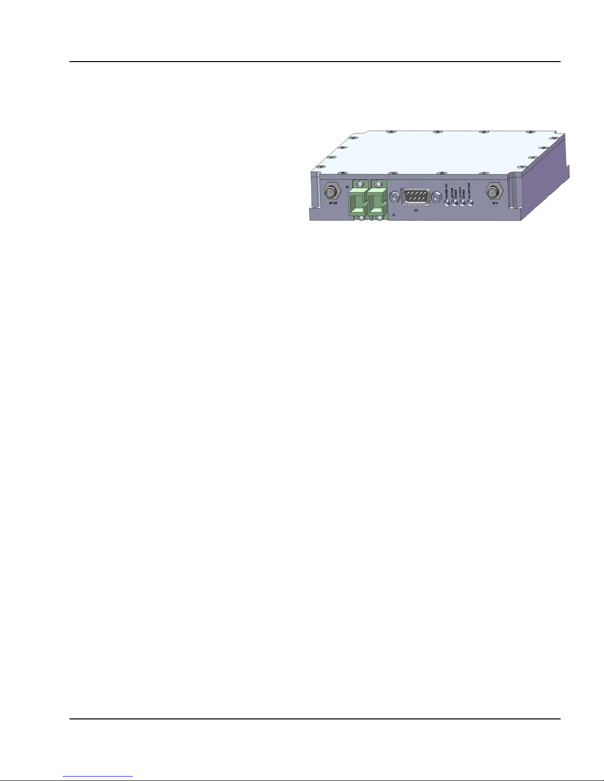
System 5000 Wideband Microwave Transceiver fiber optic intra-facility links are a highperformance, cost-effective alternative to coaxial cable. They provide much longer transmission
distances than copper cables, which simplify network design, ease installation and even enhance
immunity from EMI, RFI and lightning. These transmitters and receivers take the best RF design
features of Emcore’s extensive families of products and combine them into a compact package
compatible with the 10901G Power Supply.
The System5000 Wideband Microwave Transceiver family’s wide range of RF with a single
chassis. The final result is a system that can be factory or user custom configured to meet a wide
range of fiber transport applications.
Copyright © 2008 Emcore Corporation MAN-5021TR, Rev B
Page 4
Emcore Corporation
Interface
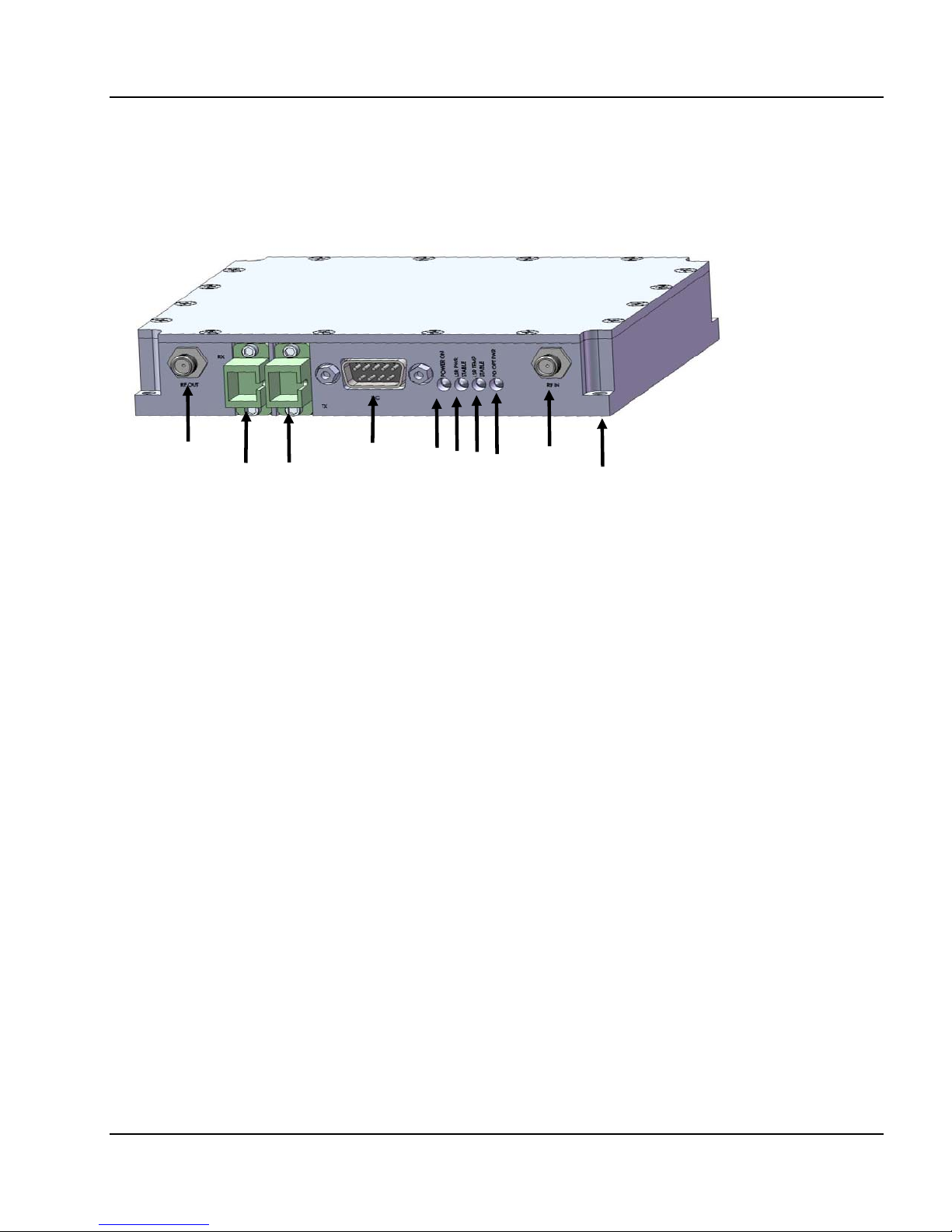
Figure 01
System 5000 series
6
7
8
9
1
2 3
4
5
10
1. Power This LED illuminated indicates when DC power is present and off when there is no DC
power.
2. Laser Power The LED illuminated indicates the laser is operating 10% above its set-point.
3. Laser Temp This LED illuminated indicates the laser is operating within 2% of its set-point.
4. Photodiode Optical Power The LED illuminated indicates the photodiode is receiving optical
power greater the –12 dBm.
5. RF Input
6. RF output
7. Optical Input (SC/APC shown)
8. Optical Output (SC/APC shown)
9. DC Power
10. Mounting
Copyright © 2008 Emcore Corporation MAN-5021TR, Rev B
Page 5

Emcore Corporation
System 5000 series
Installation
Module Installation
Apply DC power
Verify that the Power On, Laser Power and Laser Temp are illuminated.
The LED’s illuminated will be in respect to the device option selected. Selectable options
are, TR – Transceiver and T – Transmitter.
Connect RF input and output signal cables.
Insert either the SC/APC or FC/APC connector of the fiber jumper in the fiber output
connector socket.
Insert the opposite end of the SC/APC or FC/APC connector of the fiber jumper to the fiber
input connector.
Verify that the Optical Power LED is now illuminated and that the link is established.
DC Interface (Table 01)
Pin
Number
1 +15 VDC
2 +5 VDC
3 Not Used
4 Ground
5 Ground
6 Optical Current Monitor
7 Summary Alarm Common
8 Laser Current Monitor
9 Summary Alarm
Function
Operation
Every step has been taken to ensure simple hands free operation. This will provide the lowest
possible distortion.
Transceiver (TR)
After ensuring that the 5021TR is setup and powered ensure the following LED’s are illuminated.
Power - Green: DC power is applied to the transmitter.
Laser Power - Green: Laser Power is operating 10% above set point.
Laser Temp - Green: Laser Temperature is operating 2% from set point.
Optical Power – Off: Optical power greater than –12 dBm is received.
Only after the optical input is connected to the optical input of the 5021TR will the Optical Power
LED be illuminate Green.
Verify that the transceiver has the specified optical output, refer to the supplied test data sheet.
Copyright © 2008 Emcore Corporation MAN-5021TR, Rev B
Page 6
Emcore Corporation
System 5000 series
Verify that the fiber is terminated with either a SC/APC or FC/APC connector, failure to use the
correct connector will result in higher than expected losses and poor system performance.
From the supplied data sheet for the transceiver locate the measure TG and RG values respectively.
The numbers added too 2*(Optical Loss) dB will give the overall system gain.
LED Indicator Tables & Diagram
TX Status LED (Table 02)
LED,
Alarm
Off Green Power DC Power, present
Off Green Laser Power Laser Power, 10%
Off Green Laser Temp
Off Green Optical Power Optical power > -12
LED,
Good
“Transceiver”
LED
Notes,
Good State
above set point
Laser Temp, 2%
above set point
dBm
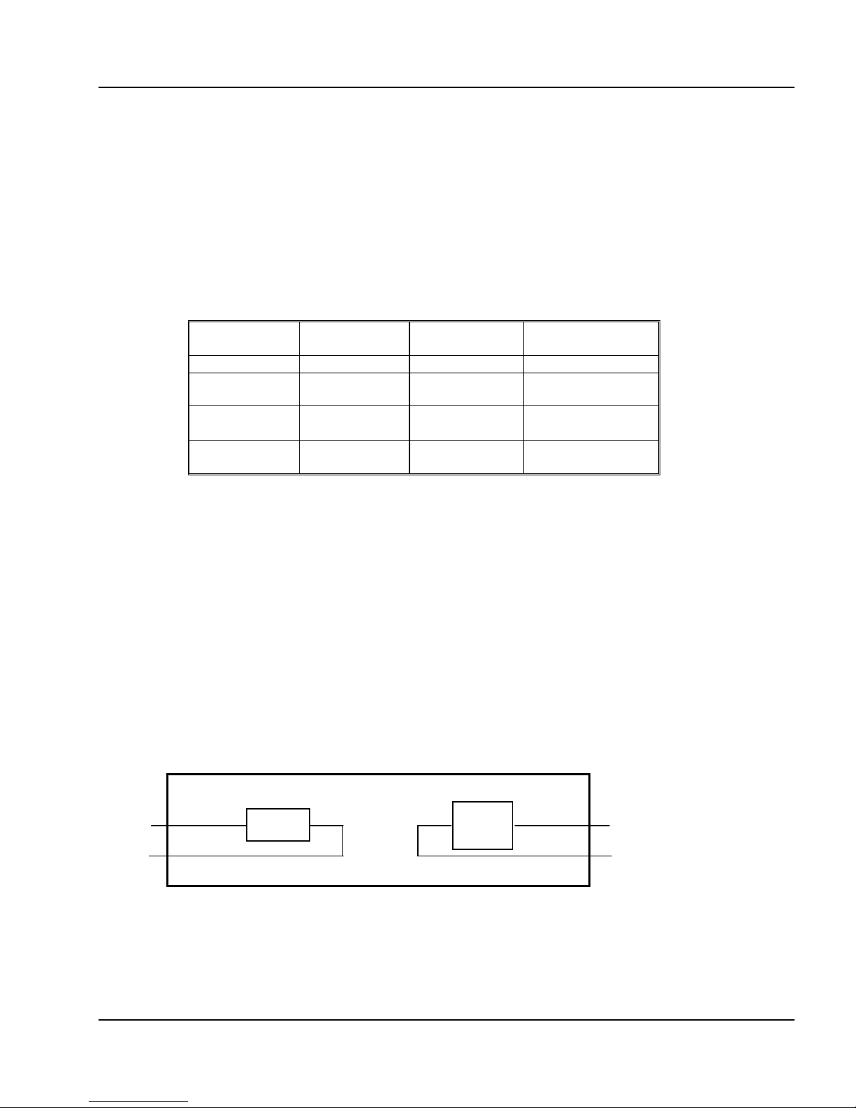
System 5000 Wideband Fiberoptic Transmission System
S
S
L
Laser
Photo
diode
-
P
S
out
P
R
5021 Transceiver
S
in
P
L
Txcvr
Copyright © 2008 Emcore Corporation MAN-5021TR, Rev B
Page 7

Emcore Corporation
System 5000 series
Remote Monitoring
Discrete
The System 10000 System is designed to provide remote status. Use of this feature requires the use
of a network management system that can accept discrete inputs.
5021 (TR -Transceiver)
Monitored Values
Laser Current
Photodiode Current
Summary Alarm
1V/100mA
1V/1mA
Dry Contact – Sums the Laser Temp, Laser
Power and Photodiode Low Optical Power
alarm
Specifications
5021TR
RF Frequency 50 MHz – 22 GHz
Laser Power +8 to +10 dBmo
RF Flatness 7 dB max (pp)
RF Return loss >-4 dB
Carrier/Noise ratio 115 dB/Hz(*)
Carrier/Intermod Ratio >55 dB(*)
Spur Free Dyn Range* 98 dBHz
* (Two tones peaked)
Photodiode input -12 to +10 dBmo
rd
3
order intercept, >25 dBm
2/3
System 5000 General
Certifications CE,CSA,FCC,
Operating Temperature -40 to 60C
Storage Temperature -40 to 85C
Humidity, non-condensing 5 to 95%
Dimensions (HxWxD) 1.00” x 5.00” x 5.00”
Weight, Typical 3.0 lbs
Photodiode Current 10 mA max
RF Flatness 5 dB max (pp)
RF Return loss >-4 dB
Transmit Gain (TG) -24 dB
Receive Gain (RG) -11 dB
System Gain (SG) -35 dB
Copyright © 2008 Emcore Corporation MAN-5021TR, Rev B
Page 8

Emcore Corporation
System 5000 series
Ordering Information
Model Number
Model Number
Each Emcore product is assigned a unique model number and serial number, which
appears on the label of the unit. Model numbers for this series have the form 5021XX-Y-ZZ
here; ‘X’ is a two letter designation specifying the appropriate unit option TR – Transceiver,
Y” is a one letter designation for frequency (A, B, C, D and E), “and ‘ZZ’ is a two letter
designation for the appropriate optical connector SA – SC/APC or FA – FC/APC.
Model Number Description
Transceiver
5021TR-A-SA-1309 Txcr, 3 GHz, 50 Ohm SMA, 1310nm, 9 dBm SC-APC
5021TR-A-FA-1309 Txcr, 3 GHz, 50 Ohm SMA, 1310nm, 9 dBm FC-APC
5021TR-B-SA-1309 Txcr, 7 GHz, 50 Ohm SMA, 1310nm, 9 dBm SC-APC
5021TR-B-FA -1309 Txcr, 7 GHz, 50 Ohm SMA, 1310nm, 9 dBm FC-APC
5021TR-C-SA -1309 Txcr, 13 GHz, 50 Ohm SMA, 1310nm, 9 dBm SC-APC
5021TR-C-FA -1309 Txcr, 13 GHz, 50 Ohm SMA, 1310nm, 9 dBm FC-APC
5021TR-D-SA -1309 Txcr, 18 GHz, 50 Ohm SMA, 1310nm, 9 dBm SC-APC
5021TR-D-FA -1309 Txcr, 18 GHz, 50 Ohm SMA, 1310nm, 9 dBm FC-APC
5021TR-E-SA -1309 Txcr, 22 GHz, 50 Ohm SMA, 1310nm, 9 dBm SC-APC
5021TR-E-FA -1309 Txcr, 22 GHz, 50 Ohm SMA, 1310nm, 9 dBm FC-APC
Power Supplies
10901G-NA Power Supply for 10990A North America AC cord
10901G-UK Power Supply for 10990A United Kingdom AC cord
10901G-EU Power Supply for 10990A European AC cord
8218-003 DC power cable for use with the 10901G Power Supply
8218-002 DC power cable for use with the Laboratory Power Supply
Accessories
5220-037 3 Meter SC/APC to SC/APC jumper
XXXX-XXX 5016 adapter plate
Copyright © 2008 Emcore Corporation MAN-5021TR, Rev B
Page 9

Emcore Corporation
System 5000 series
Optics Handling & Safety
Working with fiber optic cables and interfaces require a clean dust free environment. The optical power is
confined in the optical core only a few microns in diameter. Small particles of dust can block the proper
transfer of light through the connectors. It is therefore important to keep connectors as clean as possible,
and when in doubt of the cleanliness of a connector, clean it prior to inserting into a transmitter or receiver
receptacle.
A number of events can damage fiber optic connectors. Unprotected connector ends can experience
damage by impact, airborne dust particles, or excess humidity or moisture. Never touch the fiber end face of
the connector.
When cleaning fiber optic connectors use only Industrial grade 99% pure isopropyl alcohol, lens-grade, lintfree tissue, and optionally canned dry air. Alternatively, there are a number of simple, effective products that
are specifically designed for cleaning fiber optic connectors.
Never look onto an illuminated fiber end.
Disclaimer
Every attempt has been made to make this material complete, accurate and up-to-date. Users are cautioned
that EMCORE reserves the right to make changes without notice and shall not be held responsible for any
damages, including consequential, caused by reliance on the material presented, including, but not limited
to, typographical, arithmetical, or listing errors.
WARNINGS, CAUTIONS, LIABILITY, WARRANTY AND GENERAL NOTES
Safety Considerations
When installing or using this product, observe all safety precautions during handling and operation. Failure
to comply with the following general safety precautions and with specific precautions described elsewhere
in this manual violates the safety standards of the design, manufacture, and intended use of this product.
Emcore assumes no liability for the customer's failure to comply with these precautions.
The fiberoptic laser transmitter used in Emcore’s System 5000 link contains a class IIIb laser product as
defined by the U.S. Department of Health and Human Services, Public Health Service, Food and Drug
Administration. This laser product complies with 21 CFR, Chapter I, Subchapter J of the DHEW standards
under the Radiation Control for Health and Safety Act of 1968.
The laser operates at nominally 1310 nm with less than 30 mW optical output. The typical optical output for
this product is less than 10 mW. The protective laser plug-in module housing prevents a user from being
exposed to hazardous optical output levels. Since there is no human access to the laser output during
system operation, no special operator precautions are necessary when fiber is connected to the transmitter
and receiver. During installation, service, or maintenance, the service technician is warned to not look
directly into the end of the fiber connector or the fiber. The light emitted from the fiberoptic connector or any
fiber connected to the transmitter is invisible and may be harmful to the human eye. Use either an infared
fluorescent screen or an optical power meter for optical output verification. All handling precautions as
outlined by Federal agencies or other authorities of class IIIb lasers must be observed.
Do not attempt to modify or to service the laser diode module. Return it to Emcore for service and repair.
Contact the Emcore Customer Service Department for a return authorization and further instructions.
Copyright © 2008 Emcore Corporation MAN-5021TR, Rev B
Page 10

Emcore Corporation
System 5000 series
Electrostatic Sensitivity
Observe electrostatic precautionary procedures. Semiconductor laser transmitters and receivers provide
highly reliable performance when operated in conformity with their intended design. However, a
semiconductor laser may be damaged by an electrostatic charge inadvertently imposed by careless
handling.
Static electricity can be conducted to the laser chip from the center pin of the RF input connector, and
through the DC connector pins. When unpacking and otherwise handling the transmitter, follow ESD
precautionary procedures including use of grounded wrist straps, grounded workbench surfaces, and
grounded floor mats.
Exposure to electrostatic charge is greatly reduced after the transmitter or receiver has been installed in an
operational circuit.
Service
Do not attempt to modify or service any part of the system other than in accordance with procedures
outlined in this Operation Manual. If the system does not meet its warranted specifications, or if a problem
is encountered that requires service, return the apparently faulty plug-in or assembly to Emcore for
evaluation in accordance with Emcore's warranty policy.
When returning a plug-in or assembly for service, include the following information: Owner, Model Number,
Serial Number, Return Authorization Number (obtained in advance from Emcore's Customer Service
Dept.), service required and/or description of the problem encountered.
Warranty
Emcore warrants to the original purchaser all standard products sold by Emcore to be free of defects in
material and workmanship for one (1) year from date of shipment from Emcore. During the warranty
period, Emcore's obligation, at our option, is limited to repair or replacement of any product that Emcore
proves to be defective. This warranty does not apply to any product that has been subject to alteration,
abuse, improper installation or application, accident, electrical or environmental over-stress, negligence in
use, storage, transportation, or handling.
This warranty is the only warranty made by Emcore and is in lieu of all other warranties, expressed or
implied, except as to title, and can be amended only by a written instrument signed by an officer of Emcore.
Emcore sales agents or representatives are not authorized to make commitments on warranty returns.
Limitations of Liabilities
Emcore's liability on any claim of any kind, including negligence, for any loss or damage arising from,
connected with, or resulting from the purchase order, contract, or quotation, or from the performance or
breach thereof, or from the design, manufacture, sale, delivery, installation, inspection, operation or use of
any equipment covered by or furnished under this contract, shall in no case exceed the purchase price of
the device which gives rise to the claim.
EXCEPT AS EXPRESSLY PROVIDED HEREIN, EMCORE MAKES NO WARRANTY OF ANY KIND,
EXPRESSED OR IMPLIED, WITH RESPECT TO ANY GOODS, PARTS AND SERVICES PROVIDED IN
CONNECTION WITH THIS AGREEMENT INCLUDING, BUT NOT LIMITED TO, THE IMPLIED
WARRANTIES OF MERCHANTABILITY AND FITNESS FOR A PARTICULAR PURPOSE. EMCORE
SHALL NOT BE LIABLE FOR ANY OTHER DAMAGE INCLUDING, BUT NOT LIMITED TO, INDIRECT,
SPECIAL OR CONSEQUENTIAL DAMAGES ARISING OUT OF OR IN CONNECTION WITH
Copyright © 2008 Emcore Corporation MAN-5021TR, Rev B
Page 11

Emcore Corporation
System 5000 series
FURNISHING OF GOODS, PARTS AND SERVICE HEREUNDER, OR THE PERFORMANCE, USE OF,
OR INABILITY TO USE THE GOODS, PARTS AND SERVICE.
Emcore will not be responsible for loss of output or reduced output of opto-electronic devices if the
customer performs chip mounting, ribbon bonding, wire bonding, fiber coupling, fiber connectorization, or
similar operations. These processes are critical and may damage the device or may affect the device's
output or the fiber output.
Emcore test reports or data indicating mean-time-to-failure, mean-time-between-failure, or other reliability
data are design guides and are not intended to imply that individual products or samples of products will
achieve the same results. These numbers are to be used as management and engineering tools, and are
not necessarily indicative of expected field operation. These numbers assume a mature design, good
parts, and no degradation of reliability due to manufacturing procedures and processes.
Emcore is not liable for normal laser output degradation or fiber coupling efficiency degradation over the life
of the device.
Every attempt has been made to make this material as complete and accurate and up to date. Users are
cautioned that Emcore reserves the right to make changes without notice and shall not be held
responsible for any damages, including consequential, caused by reliance on the material presented,
including, but not limited to, typographical, arithmetical, or listing errors.
Copyright 2009 EMCORE Corporation
Copyright © 2008 Emcore Corporation MAN-5021TR, Rev B
 Loading...