


GENERAL DESCRIPTION
The EMCOModelV-201s a high quality, 31 range multimeter, provided with a 50 microampere, D’Arsonval meter
movement to give a sensitivity of 20,000 ohms per volt on DC and 1000 ohms per volt on AC. This high sensitivity
results in light loading and, therefore, minimum disturbance in the circuit under test, an indispensable feature for
accurate measurement. The quality of this instrument is further exemplified by the inclusion of wire-wound
potentiometers (shunting and in series with the rectifier), which are factory adjusted to compensate for the individual
characteristics of the rectifier in your instrument. This built-in EMCO feature assures you of standardized accuracy
over a wide range of measurements.
This instrument provides AC and DC voltage measurement from .1 volt (on the 2.5 volt scale) to 5000 volts (an internal
high voltage multiplier is included). It also provides DC current measurement from 1 microampere (on the 50
microampere scale) to 10 amperes. Resistance ranges to 20 megohms, output, and decibel ranges bring the total number
of useful ranges to 31. An added feature of this instrument is an internal blocking capacitor that can be switched when
it is desired to measure the output signal voltage in circuits where DC is present.
Easy reading with less probability of error is obtained with a large 4-1/2" meter. The instrument is ruggedly housed in a
polished, high-impact bakelite case with a genuine leather carrying handle.
These instruments have the wide scope of ranges, sensitivity, and accuracy that are necessary in television, f-m, and am servicing and manufacture. They are simply operated, easily read, and rugged enough for hard daily use.
SPECIFICATIONS
Ranges
DC Voltage 0 to 0.25, 2.5, 10, 50, 250, 1000, 5000 volts at 20,000 ohms per volt
AC Voltage 0 to 2. 5, 10, 50, 250, 1000, 5000 volts at 1000 ohms per volt
DC Current 0 to 50 ua, 10 ma, 100 ma, 500 ma,
10 amperes ( 250 millivolt drop across the meter)
Output Voltage 0 to 2.5, 10, 50, 250, 1000, 5000 volts (. 1 mfd internal series capacitor)
1

Decibels -12 to -55 db in 5 ranges (calibrated for use across a 500 ohm line
Resistance Range Center Scale
0 to 2000 ohms (12 ohms)
0 to 0.2 meg (1200 ohms)
0 to 20 megs (120,000 ohms)
Overall Dimensions 6-3/4" X 5-1/4" X 3"
Weight 2-3/4 pounds with batteries
Cabinet Highly polished black Bakelite
Panel Highly polished black Bakelite
Meter 4-1/2 inch face, 50 ua movement
OPERATING INSTRUCTIONS
Zero Adjustment
The slotted screw directly beneath the meter face is used to adjust the position of the meter pointer if it is off zero
(when no measurement is being made). To bring the meter pointer to zero, use a small screwdriver to turn the screw
either right or left as is necessary. This adjustment should be made before taking readings.
D-C Voltage Measurement
a. Set the DC-AC-OUTPUT switch to the DC position.
b. Set the RANGE switch to the voltage range that you can reasonably expect will include the voltage you are
measuring. If you are in doubt about the voltage present, always set the switch at the highest voltage range before
applying the unknown voltage to the instrument. Failure to observe this precaution may result in serious damage to the
meter. If the unknown voltage is too low for accurate measurement on the highest range, rotate the RANGE switch
towards the lowest voltage position until the range is found at which the voltage can be read accurately.
c. When a voltage is being measured on any range except the 5000 volt range, insert the test leads in the jacks
marked + (POSITIVE) and - COMMON. Place a test lead at each of the two points between which the DC voltage is to
be measured, observing polarities. If you have mistaken the polarities, the pointer will be deflected left of zero, in
which case simply reverse the test leads.
d. Voltages in either the 1000 or the 5000 volt range are measured with the RANGE switch in the 1KV-5KV
position. To use the 5000 volt range insert the test leads in the pin Jacks marked - COMMON and D. C. 5000 V.
CAUTION: Extreme care must be exercised when making measurement on the 5000 volt range, as high voltage is
dangerous. Never fail to turn off the
2

power when connecting or disconnecting the test leads. The meter and the leads must not be handled while the power is
on.
e. DC voltages are read on the black 0-10, 0-50, 0-250 scales marked D.C. When using the 10, 50, and 250 volt
ranges, the meter may be read directly. To obtain the indicated voltage in volts on the 2.5 volt range, divide the reading
on the 250 scale by 100. For readings on the 0.25 volt range, divide the reading on the 250 scale by 1000. On the 1000
volt range, multiply the reading on the 10 scale by 100; on the 5000 volt range, multiply the reading on the 50 scale by
100 to obtain the indicated voltage in volts.
AC Voltage Measurement
The instructions for AC voltage measurement are the same as those for DC voltage measurement, with the following
differences in procedure and reading.
a. Set the DC-AC-OUTPUT switch to the AC position.
b. To use the 5000 volt range, insert the test leads in the pin jacks marked "-" COMMON and A.C. 5000V.
CAUTION: Extreme care must be exercised when making measurement on the 5000 volt range, as high voltage is
dangerous. Never fail to turn off the power when connecting or disconnecting the test leads. The meter and the leads
must not he handled while the power is on.
c. Read the red 0-10, 0-50, 0-250 scale marked A. C. on all voltage ranges except the 2.5 volt range, which is read
on the red 0-2.5 scale marked 2.5V.A.C.
d. The reading of the meter scales corresponding to each range position is the same as for DC with the exception
of the special 2.5V.A.C. scale, which is numbered in tenths of a volt.
DC Current Measurement
CAUTION: Never place the instrument across a voltage source when it is set for current measurement. Failure to
observe this precaution may result in serious damage to the meter.
a. Set the DC-AC-OUTPUT switch to the DC position.
b. Set the RANGE switch to the current range that you can reasonably expect will include the current you are
measuring. If you are in doubt about the current present, always set the switch at the highest current range before
inserting the instrument in the circuit. Failure to observe this precaution may result in serious damage to the meter. If
the unknown current is too low for accurate measurement on the highest range, rotate the RANGE switch towards the
lowest current position until the range is found at which the current can be read accurately.
c. When a current is being measured on any range except the 10 amp. range, insert the test leads into the pin jacks
marked + (POSITIVE) and - COMMON and place the instrument in series with the component through
3

which the current to be measured is flowing (observing current direction). If you have mistaken the direction of current
flow, the pointer will be deflected left of zero, in which case simply reverse the test leads.
d. Currents in either the 10 ma range or the 10 amp. range are measured with the RANGE switch in the 10MA10AMP. position. To use the 10 amp. range, insert the test leads in the pin jacks marked +10 AMP and -10 AMP,
taking care to observe the direction of current flow.
e. DC currents are read on the black 0-10 and 0-50 scales marked D. C. When using the 10 ma and 10 ampere
ranges, read the 10 scale directly in ma and amperes, respectively. To obtain the indicated current on the 100 ma range,
multiply the reading on the 10 scale by 10 and read ma. Read the 0-50 scale directly for measurements made on the 50
ua scale. On the 500 ma scale, multiply the reading on the 50 scale by 10 and read in ma.
Resistance Measurement
a. Set the DC-AC-OUTPUT switch to the DC position.
b. If you are measuring a resistance less than 150 ohms, set the RANGE switch at the RX1 position. For a
resistance between 150 and 15,000 ohms, use the RXI00 position; and for s resistance above 15,000 ohms, use the
RX10K position.
c. Insert the test leads into the Jacks marked + (POSITIVE) and - COMMON.
d. To zero adjust on any range, short the test leads and rotate the ZERO OHMS knob until the meter pointer is set
directly over the zero of the top black scale marked OHMS.
e. Connect the test leads across the component whose resistance is to be measured. On the RX1 range, read the
scale directly in ohms, To obtain the indicated resistance in ohms on the RX100 and the RX10K ranges, multiply the
scale reading by 100 and 10,000, respectively.
Output Voltage Measurement
The instructions for output voltage measurement are the same u those for AC voltage measurement, with the exception
that the DC-AC-OUTPUT switch is set at the OUTPUT position.
Consideration should be given, however, to the effect of the blocking capacitor when measuring on the 2.5V range at
frequencies less than 1000 Hz, the 10V range below 250 Hz, and the 50V range below 60 Hz. On these ranges, below
the frequencies given, the ratio of the reactance of the blocking capacitor to the multiplier resistance for the range is too
high to neglect the bleeding of the applied voltage by the blocking capacitor. The graph in figure 1 has been prepared
so that measurement can be made in these cases. The graph is used in the following way:
4
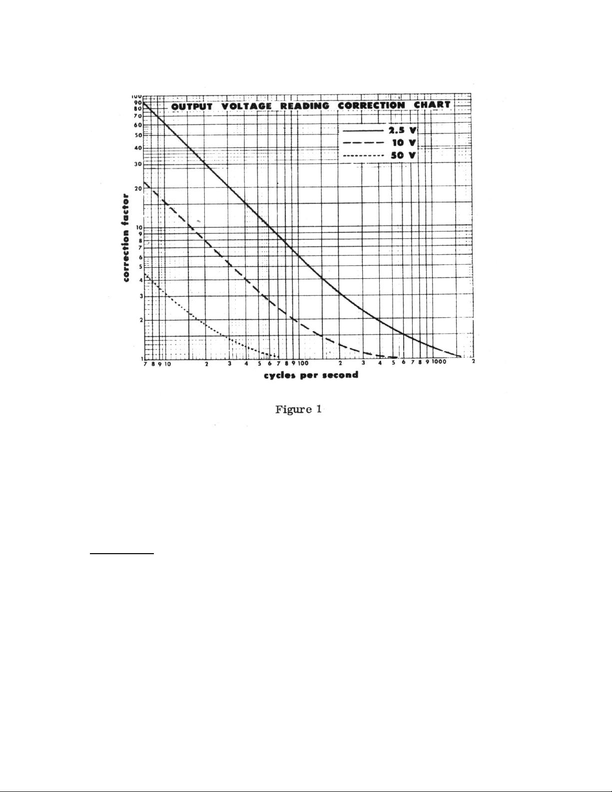
a. Find the point corresponding to the frequency of the applied voltage on the horizontal scale marked "cycles per
second.”
b. Trace upwards from that point until you strike the curve corresponding to the range on which you are
measuring.
c. Trace along the horizontal line from that point until you strike the vertical scale marked "correction factor."
d. Multiply the voltage indicated on the meter by the correction factor obtained from the graph to find the true
voltage.
DB Measurement
The instructions for db measurement are the same as those for AC voltage measurement, except for the reading of the
meter scales.
When using the 2. 5 volt position, the DB scale is read directly; for all other ranges it will be necessary to algebraically
add the number of db charted on the right hand side of the meter face. For example, if the RANGE selector switch is set
at 250 volts and the meter indicates + 1DB, the actual reading would be 40 + 1 = 41db. As a further example, if the
meter in the 10 volt position reads -8DB, the actual reading would be -8 + 12 = 4db.
5
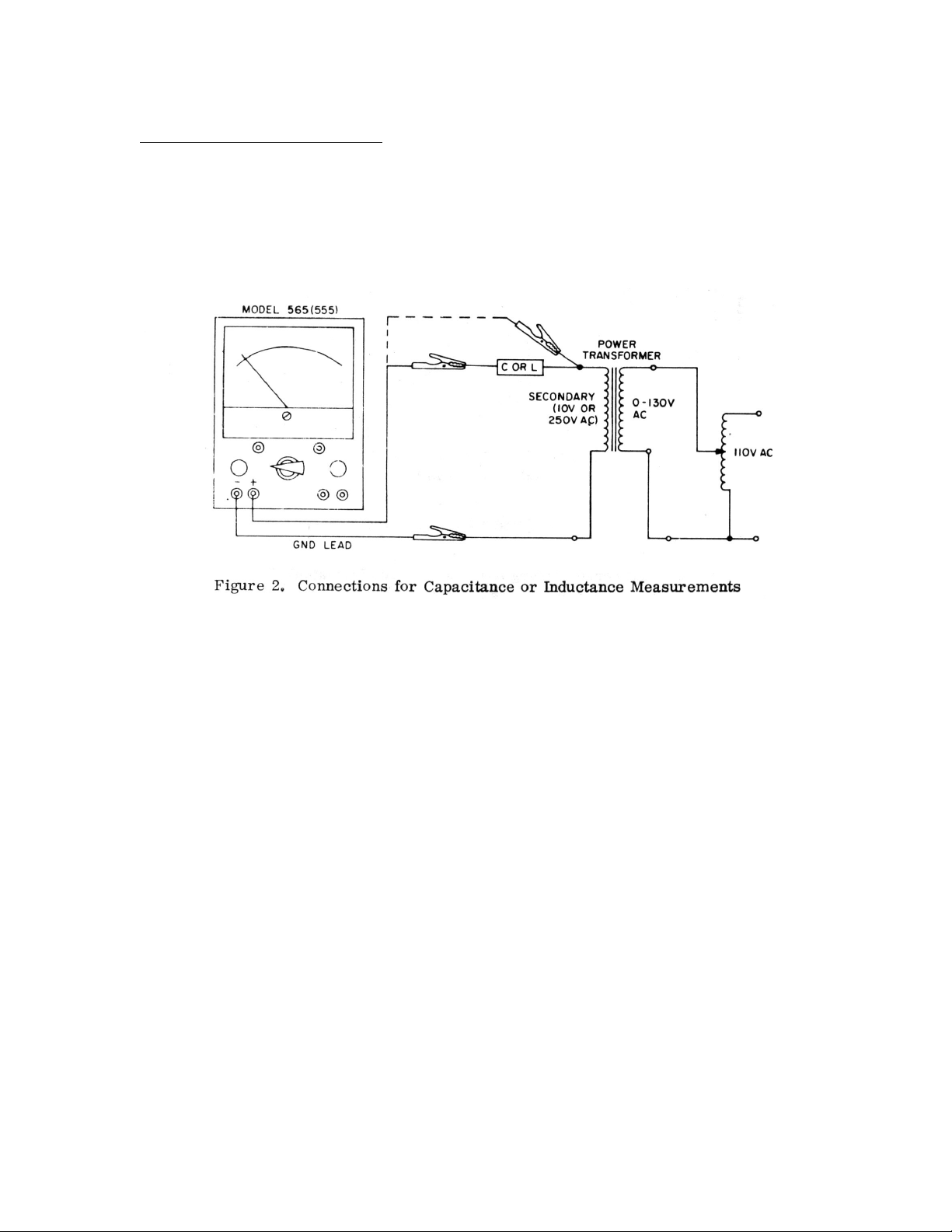
Capacitance and Inductance Measurements
NOTE: An external AC power source is required to make
capacitance and inductance measurements.
1. Set up the MODEL V-20 and the external power source as shown in figure 2.
WARNING:
Make certain the external power source is off before connecting the capacitance or inductance to be measured.
2. For capacitance readings of .009 MF to 1MF or for inductance readings, set the DC-AC-OUTPUT switch to AC
and the RANGE switch to 10V, and (with the meter leads connected across the secondary of the power transformer)
adjust the external power source for a full-scale reading of 10 volts rms. For capacitance readings of .0001 MF to. 03
MF, set the RANGE switch to 250V, and adjust the external power source for a full-scale reading of 250 volts rms.
CAUTION: Adjust the external power source starting from its lowest voltage so as not to overload the meter on the
selected scale.
3. With the capacitance or inductance in series with the secondary of the power transformer, as shown in figure
read the voltage on the meter; then refer to table 1 (capacitance of .009 MF to IMF), table 2 (capacitance of. 0001 MF
to .03 MF), or table 3 (inductance of 5H to 1000H) to ob/n t-the corresponding value of capacitance or inductance.
6
2,
 Loading...