

Page 1

histnictim
book
Coordinate
Englisch
Auflage;
Milling
Order
10.
9.
92
91
and
No,
8.
7.
90
89
Maier+Co.
A-5400
Hallein/Austria
Drilling
EN 2 455
6.
5.
4.
3.
88
87
86
85
Machine
Page 2

SAFETY
1.
KNOW
Read
plication
potential
2.
GROUND
If
tool
should
If
adapter
receptacle,
a
known
3.
KEEP
and
in
4.
REMOVE
WRENCHES
Form
justing
turning
5.
KEEP
Cluttered
6.
AVOID
ENVIRONMENT
Don't
Keep
7.
KEEP
All
visitors
work
8.
MAKE
—
with
moving
9.
DON'T
It
will
for
which
YOUR
the
owner's
and
hazards
is
equipped
be
plugged
is
the
ground.
GUARDS
working
habit
of
wrenches
on
tool.
WORK
areas
DANGEROUS
use
power.tools
work
area
CHILDREN
should
area.
WORKSHOP
padlocks,
starter
FORCE
do
the
it
was
RULES
POWER
manual
limitations
peculiar
ALL
used
adapter
Never
order.
ADJUSTING
checking
are
AREA
and
well
keys.
job
better
designed.
carefully.
as
well
to
this
TOOLS
with
three-prong
into a three-hole
to
accommodate
wire
remove
IN
PLACE
to
see
removed
CLEAN
benches
in
damp
illuminated.
AWAY
be
kept a safe
master
switches,
TOOL
and
TOOL
as
tool.
must
be
third
KEYS
that
from
invite
accidents.
or
wet
distance
KID
PROOF
be
safer
FOR
Learn
its
ap
the
specific
plug,
it
receptacle.
two-prong
attached
prong.
keys
tool
locations.
or
at
AND
and
ad
before
from
by
the
rate
to
re
POWER
10.
USE
RIGHT
Don't
force
not
designed
11.
WEAR
No
loose
moving
12.
USE
Also
is
13.
SECURE
Use
tical.
hands
14.
DON'T
Keep
times.
15.
MAINTAIN
CONDITION
Keep
performance.
coting
16.
DISCONNECT
before
sories
17.
AVOID
Make
cord.
18.
USE
ACCESSORIES
Consult
accessories
parts.
SAFETY
use
dusty.
clamps
It's
to
your
tools
and
servicing
such
sure
RECOMMENDED
TOOL
tool
or
attachment
for.
PROPER
clothing
face
WORK
safer
operate
OVERREACH
proper
or
GLASSES
or
dust
or a vise
than
using
tool.
footing
TOOLS
sharp
and
Follow
changing
accessories.
TOOLS
and
OS
blades,
ACCIDENTAL
switch
the
is
owner's
may
be
hazardous.
TOOLS
to
do a job
APPAREL
jewelry
mask
to
clean
instructions
when
bits,
"OFF"
manual.
to
if
cutting
hold
work
your
and
IN
for
changing
cutters.
before
Use
get
when
hand,
balance
TOP
best
STARTING
plugging
of
it
was
caught
operation
frees
and
for
improper
in
prac
both
at
all
safest
lubri-
acces
in
WEARYOUR
FORESIGHT
THAN
NO
IS
BETTER
SIGHT
The
operation
objects
severe
shields
recommend
being
eye
before
spectacles,
Sears
retail
of
thrown
damage.
commencing
Wide
or
standard
or
catalog
any
power
into
Always
Vision
stores.
tool
the
eyes,
wear
power
Safety
safety
glasses . . . available
can
result
which
safety
glasses
tool
operation.
Mask
for
in
can
use
foreign
result
in
or
eye
We
over
at
Page 3
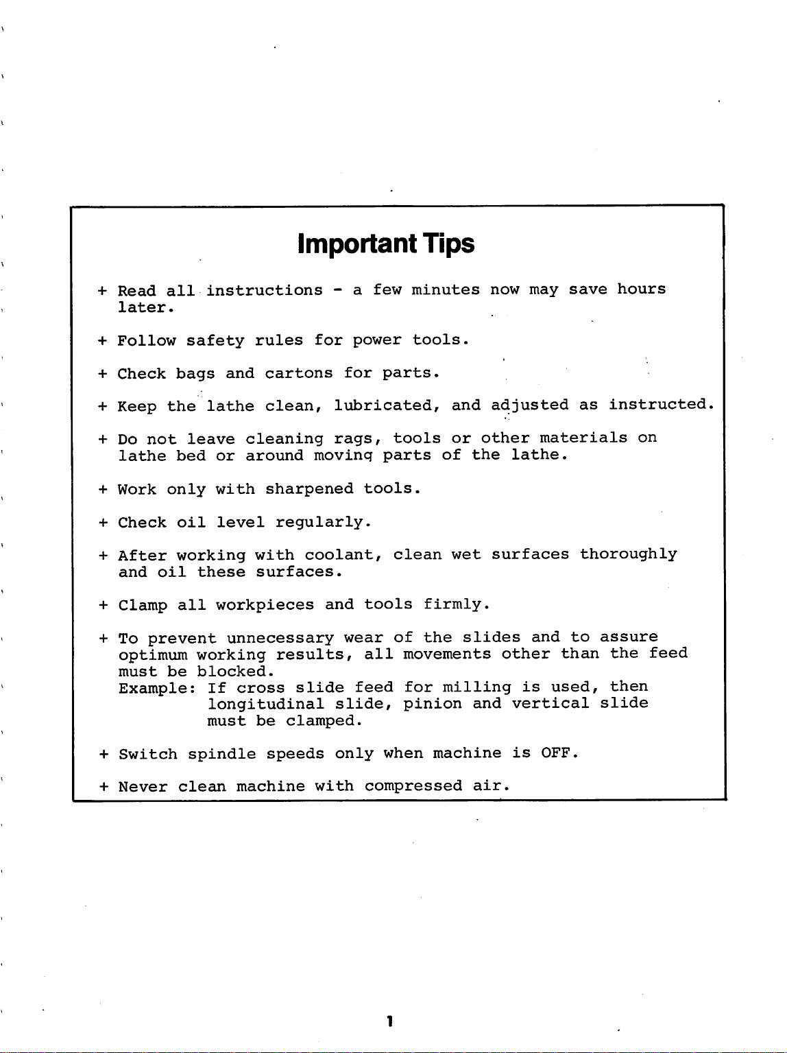
+
Read
later.
+
Follow
+
Check
+
Keep
+
Do
not
lathe
+
Work
+
Check
+
After
and
+
Clamp
+
To
prevent
optimum
must
Example:
all
safety
bags
the
leave
bed
only
oil
working
oil
these
all
working
be
blocked.
Important
instructions
rules
and
cartons
lathe
or
with
level
workplaces
If
longitudinal
must
clean,
cleaning
around
sharpened
regularly.
with
surfaces.
coolant,
unnecessary
results,
cross
be
slide
clamped.
- a few
for
power
for
parts.
lubricated,
rags,
moving
and
wear
tools
parts
tools.
clean
tools
of
all
feed
slide,
Tips
minutes
tools.
of
firmly.
the
movements
for
milling
pinion
now
and
adjusted
or
other
the
wet
surfaces
slides
and
may
materials
lathe.
and
other
is
than
used,
vertical
save
hours
as
instructed
on
thoroughly
to
assure
the
then
slide
feed
+
Switch
+
Never
spindle
clean
speeds
machine
only
with
when
compressed
machine
air.
is
OFF.
Page 4
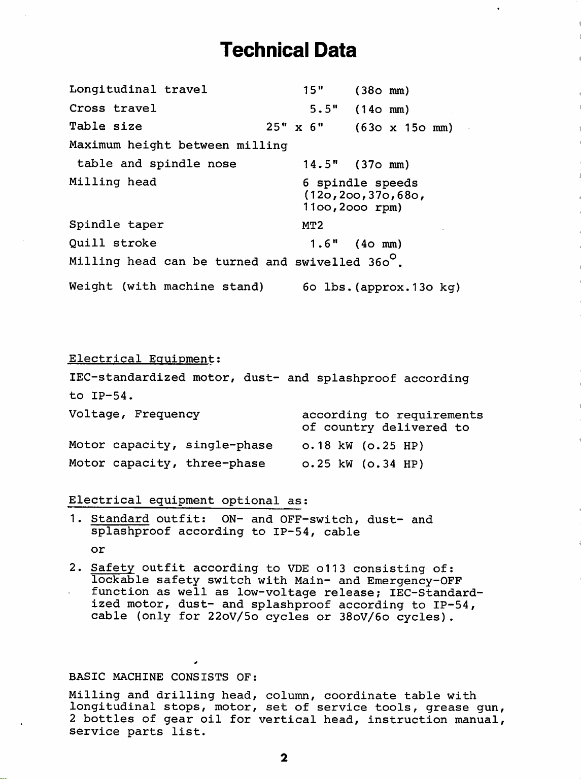
Technical
Data
Longitudinal
Cross
Table
Maximum
table
Milling
Spindle
Quill
Milling
Weight
Electrical
travel
size
height
and
head
taper
stroke
head
(with
travel
spindle
can
machine
Equipment:
lEC-standardized
between
nose
be
turned
stand)
motor,
25"
milling
and
dust-
15"
5.5"
X
6"
14.5"
6
spindle
(12o,2oo,37o,68o,
(38o
(14o
(63o
(37o
11oo,2ooo
MT2
1.6"
swivelled
6o
and
splashproof
(4o
36o°.
lbs.(approx.13o
mm)
mm)
X
15o
mm)
speeds
rpm)
mm)
according
mm)
kg)
to
IP-54.
Voltage,
Motor
Motor
capacity,
capacity,
Electrical
1.
Standard
splashproof
or
2.
Safety
lockable
function
ized
motor,
cable
BASIC
MACHINE
Frequency
single-phase
three-phase
equipment
outfit:
according
outfit
according
safety
as
well
dust-
(only
for
CONSISTS
optional
ON-
and
to
switch
as
low-voltage
and
splashproof
22oV/5o
OF:
according
of
o.18
o.25
as:
OFF-switch,
IP-54,
to
VDE
with
Main-
cycles
to
requirements
country
kW
kW
cable
delivered
(o.25
(o.34
dust-
HP)
HP)
and
oil 3 consisting
and
Emergency-OFF
release;
according
or
38oV/6o
lEC-Standard-
to
cycles).
to
of:
IP-54,
Milling
and
longitudinal
2
bottles
service
of
parts
drilling
stops,
gear
oil
list.
head,
motor,
for
column,
set
of
vertical
coordinate
service
head,
instruction
table
tools,
with
grease
manual,
gun,
Page 5
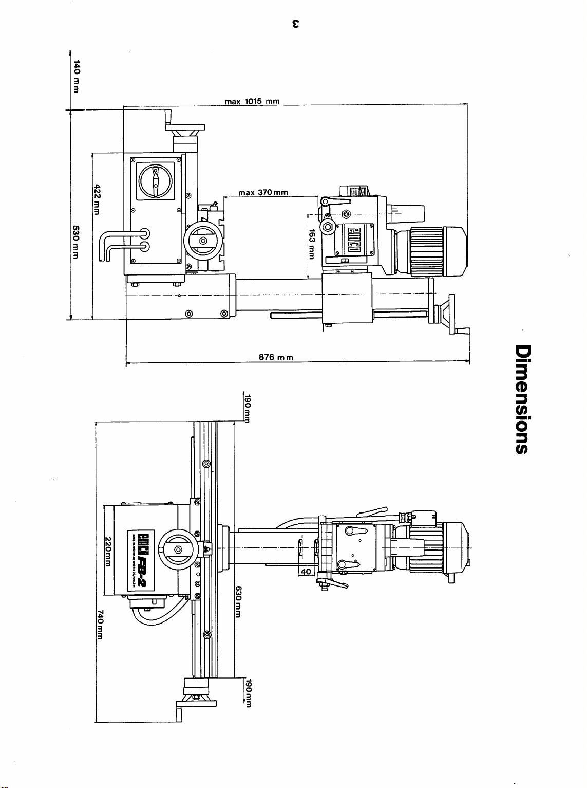
140
mm
530
mm
422
mm
0)
I
163
mm
740
mm
220
mm
Dimensions
190
mm
m
o
@
0
630
mm
190
mm
Page 6
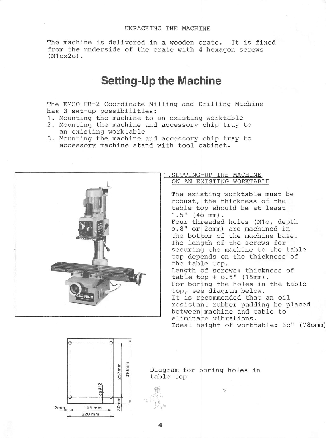
The
machine
from
(Mlox2o)
the
.
is
delivered
underside
UNPACKING
of
the
in
crate
THE
a
MACHINE
wooden
with
crate.
4
hexagon
It
is
fixed
screws
The
EMCO
has 3 set-up
1.
Mounting
2.
Mounting
an
3.
Mounting
FB-2
existing
accessory
Setting-Up
Coordinate
possibilities:
the
machine
the
machine
worktable
the
machine
machine
stand
the
Milling
to
an
and
and
with
Machine
and
existing
accessory
accessory
tool
1
.SETTING-UP
ON
AN
The
existing
robust,
table
1.5"
Four
0.8"
the
bottom
The
length
securing
top
depends
the
table
Length
table
For
boring
top,
It
is
resistant
between
eliminate
Ideal
Drilling
worktable
chip
chip
tray
tray
cabinet.
THE
EXISTING
worktable
the
thickness
top
should
(4o
mm)
.
threaded
or
2omm)
of
of
the
machine
on
top.
of
screws:
top + 0.5"
the
see
diagram
recommended
rubber
machine
vibrations.
height
of
Machine
to
to
MACHINE
WORKTABLE
be
at
holes
are
the
the
the
(Mio,
machined
machine
screws
thickness
thickness
(15mm)
holes
below.
that
padding
and
table
worktable:
of
to
in
must
the
least
depth
base.
for
the
.
the
an
oil
be
be
in
table
of
table
placed
to
3o"
of
(78omm)
196
220
Diagram
table
mm
mm
top
for
boring
holes
in
Page 7
Diagram
table
357mm
for
top
boring
for
196mm
chip
holes
tray
0
12.5
910
mm
mm
in
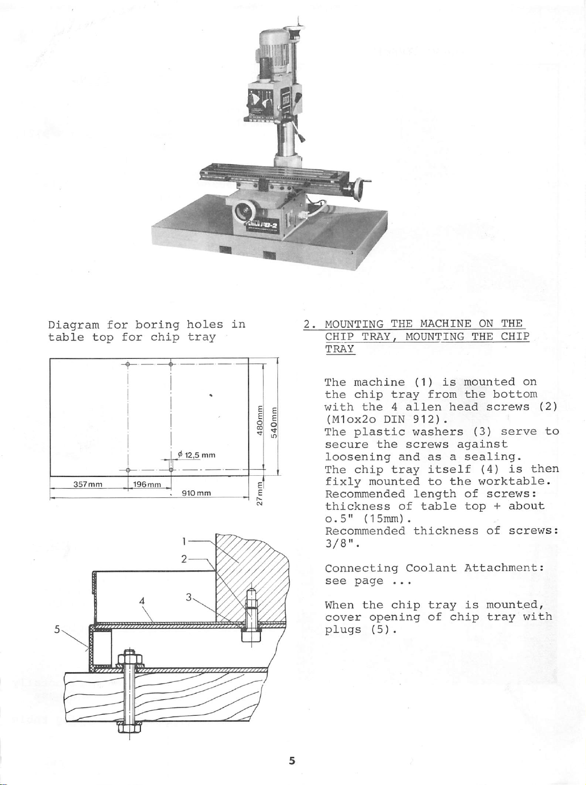
2.
MOUNTING
CHIP
TRAY
The
the
with
(iyi1ox2o
The
secure
loosening
The
fixly
Recommended
thickness
o.5"
Recommended
3/8".
THE
TRAY,
machine
chip
the
tray
4
DIN
plastic
the
chip
tray
mounted
{15mm)
MACHINE
MOUNTING
(1)
is
from
alien
912)
.
washers
screws
and
as a sealing.
itself
to
length
of
table
.
thickness
ON
THE
mounted
the
bottom
head
screws
(3)
against
(4)
the
worktable.
of
screws:
top + about
of
THE
CHIP
on
serve
is
then
screws:
(2)
to
Connecting
see
page
When
cover
plugs
the
opening
(5)
Coolant
..
.
chip
.
tray
of
chip
Attachment:
is
mounted,
tray
with
Page 8
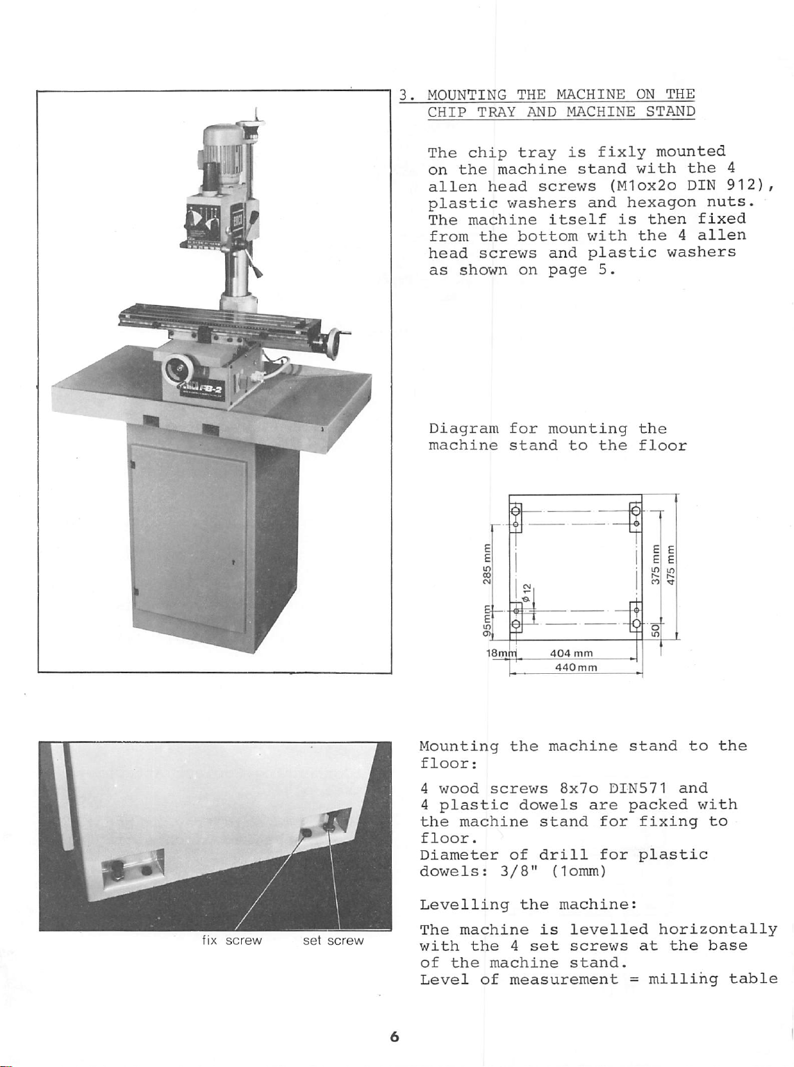
3.
MOUNTING
CHIP
The
on
alien
plastic
The
from
head
as
TRAY
chip
the
head
machine
the
screws
shown
THE
AND
tray
machine
screws
washers
itself
bottom
and
on
page
MACHINE
MACHINE
is
fixly
stand
and
with
plastic
5.
ON
STAND
mounted
with
{M1ox2o
hexagon
is
then
the
THE
the
DIN
nuts.
fixed
4
alien
washers
4
912),
Diagram
machine
Mounting
floor;
4
wood
4
plastic
the
machine
floor.
Diameter
dowels:
for
stand
the
screws
dowels
of
3/8"
mounting
to
404
mm
440mm
machine
8x7o
are
stand
drill
(lomm)
the
DXN571
for
for
the
floor
stand
packed
fixing
plastic
to
and
the
with
to
fix
screw
set
screw
Levelling
The
machine
with
of
Level
the
the
machine
of
the
machine:
is
levelled
4
set
screws
stand.
measurement
horizontally
at
the
=
milling
base
table
Page 9
- n
&
HI
mm
Handwheel
slide
Oil
level
Lever
quill
for
Adjustable
for
quill
Handwheel
longitudinal
Adjustable
longitudinal
Clamping
cross
screw
slide
for
vertical
gauge
lowering
depth
for
feed
stops
movement
for
stop
for
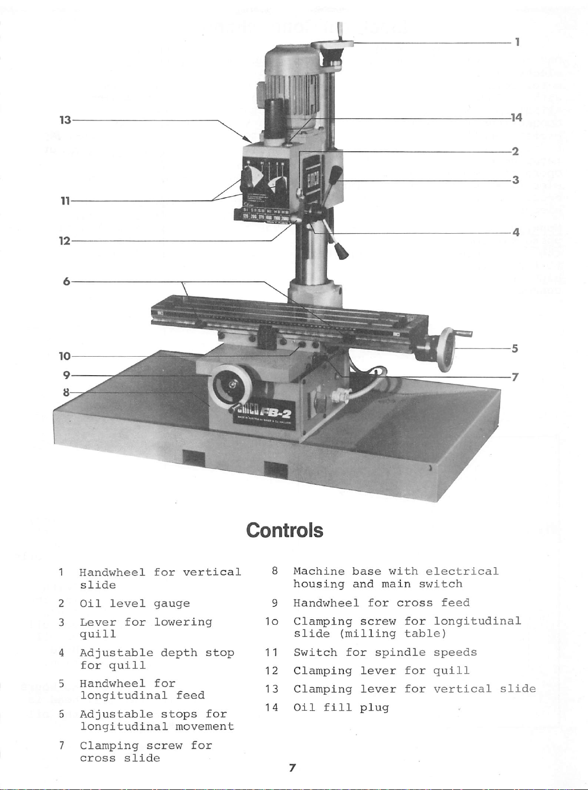
Controls
8 Machine
housing
9 Handwheel
10
Clamping
slide
11
Switch
12
Clamping
13
Clamping
14
Oil
(milling
for
fill
base
and
for
screw
spindle
lever
lever
plug
with
main
cross
for
table)
for
for
electrical
switch
feed
longitudinal
speeds
quill
vertical
slide
Page 10
Electrical
Connections
Due
to
the
various
electrical
motor
cord
receptacles,
is
with a plug.
ATTENTION:
connections
The
must
professionally.
be
connected
receptacle.
operator
electrical
occurs
electrical
Mounting
phase
the
yellow-green
to
the
blue
connected
protected
in
the
the
version;
grounding
and
brown
to
shock
equipment.
types
not
equipped
electrical
be
made
Cord
must
to a grounded
Only
then
is
from
when
motor
plug
wire
or
for
a
single-
is
contact.
wires
the
other
(MP,R)
contacts.
of
the
the
an
failure
connected
The
are
CLEANING
All
unpainted
faces
are
protective.
tective
after
machine
lightly
must
this,
surfaces
coated
THE
coated
Moxintinq
phase
The
connected
contact.
black
nected
With
it
can
runs
In
this
example,
wires)
The
shows
direction
MACHINE
machine
with
This
be
removed
all
these
must
with
the
plug
equipment:
yellow-green
to
the
The
blue,
wires
to
the
happen
in
must
arrow
the
(R,S,T)
the
other
three-phase
that
the
wrong
case,
the
blue
be
on
the
correct
of
the
sur
a
rust
rust
pro
and
unpainted
be
oil.
with
wire
three-
is
grounding
brown
are
contacts.
equipment,
the
motor
direction.
2
wires
and
(for
black
interchanged.
vertical
rotating
spindle.
and
con
head
(B
Oil
level
gauge
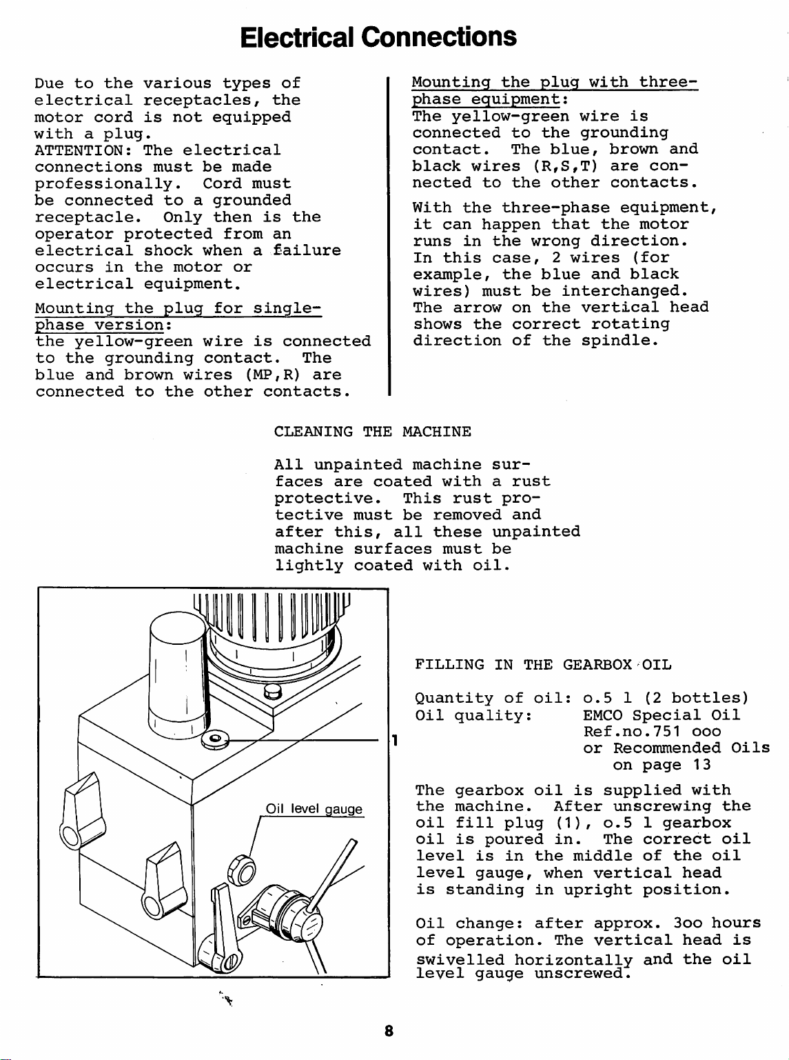
FILLING
Quantity
Oil
The
the
oil
oil
level
level
is
Oil
of
swivelled
level
8
IN
THE
of
quality:
gearbox
machine.
fill
is
plug
poured
is
in
gauge,
standing
change:
operation.
horizontally
gauge
GEARBOX
oil:
o.5 1 (2
EMCO
Ref.no.751
or
Recommended
on
oil
is
supplied
After
(1),
in.
the
when
in
upright
after
The
unscrewing
0.5 1 gearbox
The
middle
vertical
approx.
vertical
unscrewed.
OIL
bottles)
Special
page
correct
of
the
head
position.
Boo
head
and
the
Oil
ooo
Oils
13
with
the
oil
oil
hours
is
oil
Page 11
Operating
Tips
-
Adjustments
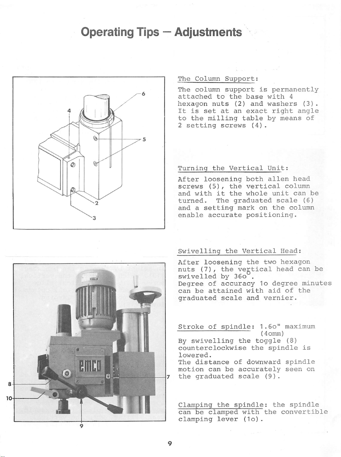
The
Column
The
column
attached
hexagon
It
is
to
the
2
setting
to
nuts
set
milling
Support;
support
the
(2)
at
an
table
screws
is
base
and
exact
(4).
permanently
with
4
washers
right
by
angle
means
(3)
of
.
Turning
After
screws
and
loosening
(5),
with
turned.
and a setting
enable
accurate
Swivelling
After
nuts
swivelled
Degree
can
loosening
(7),
of
be
attained
graduated
Stroke
By
counterclockwise
lowered.
The
motion
7 the
of
swivelling
distance
can
graduated
the
Vertical
the
it
the
The
graduated
the
the
by
accuracy
scale
spindle:
of
be
Unit:
both
vertical
whole
mark
positioning.
alien
on
Vertical
the
two
vegtical
36o
,
1o
with
and
the
downward
accurately
scale
aid
vernier.
1.6o"
{4omm)
toggle
the
spindle
(9)
head
column
unit
can
scale
the
column
Head:
hexagon
head
degree
of
maximum
(8)
spindle
seen
.
be
(6)
can
be
minutes
the
is
on
Clamping
can
be
clamping
the
clamped
lever
spindle:
with
(1o).
the
the
convertible
spindle
Page 12
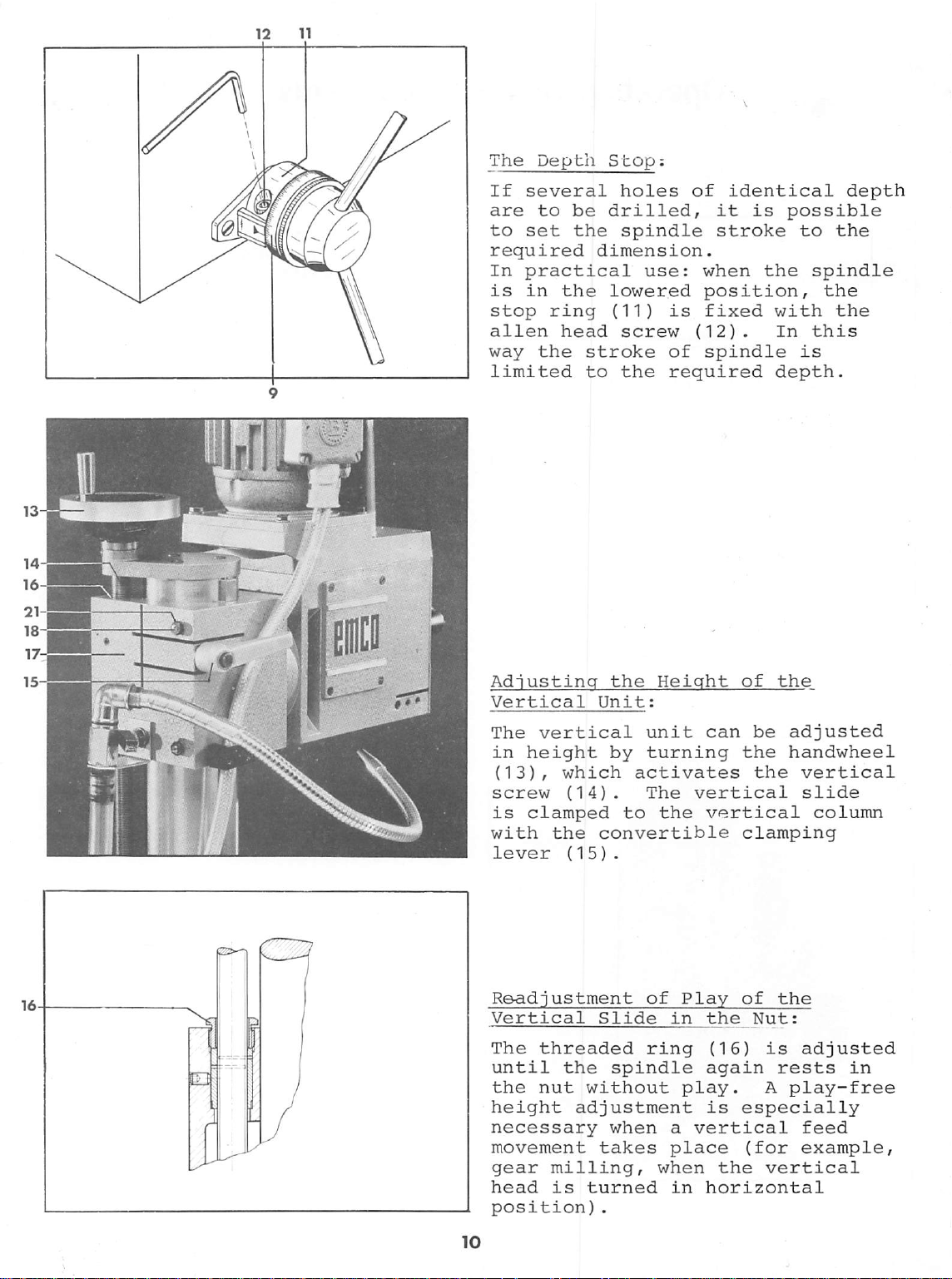
The
Depth
If
several
are
to
to
set
required
In
practical
is
in
the
stop
alien
way
ring
head
the
limited
Stop;
holes
be
drilled,
the
spindle
dimension.
lowered
(11)
screw
stroke
to
the
of
use:
is
(12)
of
required
Identical
it
is
stroke
when
the
position,
fixed
.
with
In
spindle
depth.
depth
possible
to
the
spindle
the
the
this
is
Adjusting
Vertical
The
vertical
in
height
(13)
,
which
screw
is
with
lever
Readjustment
Vertical
The
until
the
height
(14)
clamped
the
(15)
threaded
the
nut
without
adjustment
necessary
movement
gear
head
position)
milling,
is
turned
the
Height
Unit:
unit
by
turning
activates
.
The
vertical
to
the
convertible
.
of
Play
Slide
in
ring
spindle
play.
when
takes
.
a
vertical
place
when
in
of
the
can
be
the
the
vertical
clamping
of
the
the
Nut:
(16)
again
is
rests
A
is
especially
(for
the
vertical
horizontal
adjusted
handwheel
vertical
slide
column
adjusted
in
play-free
feed
example,
Page 13
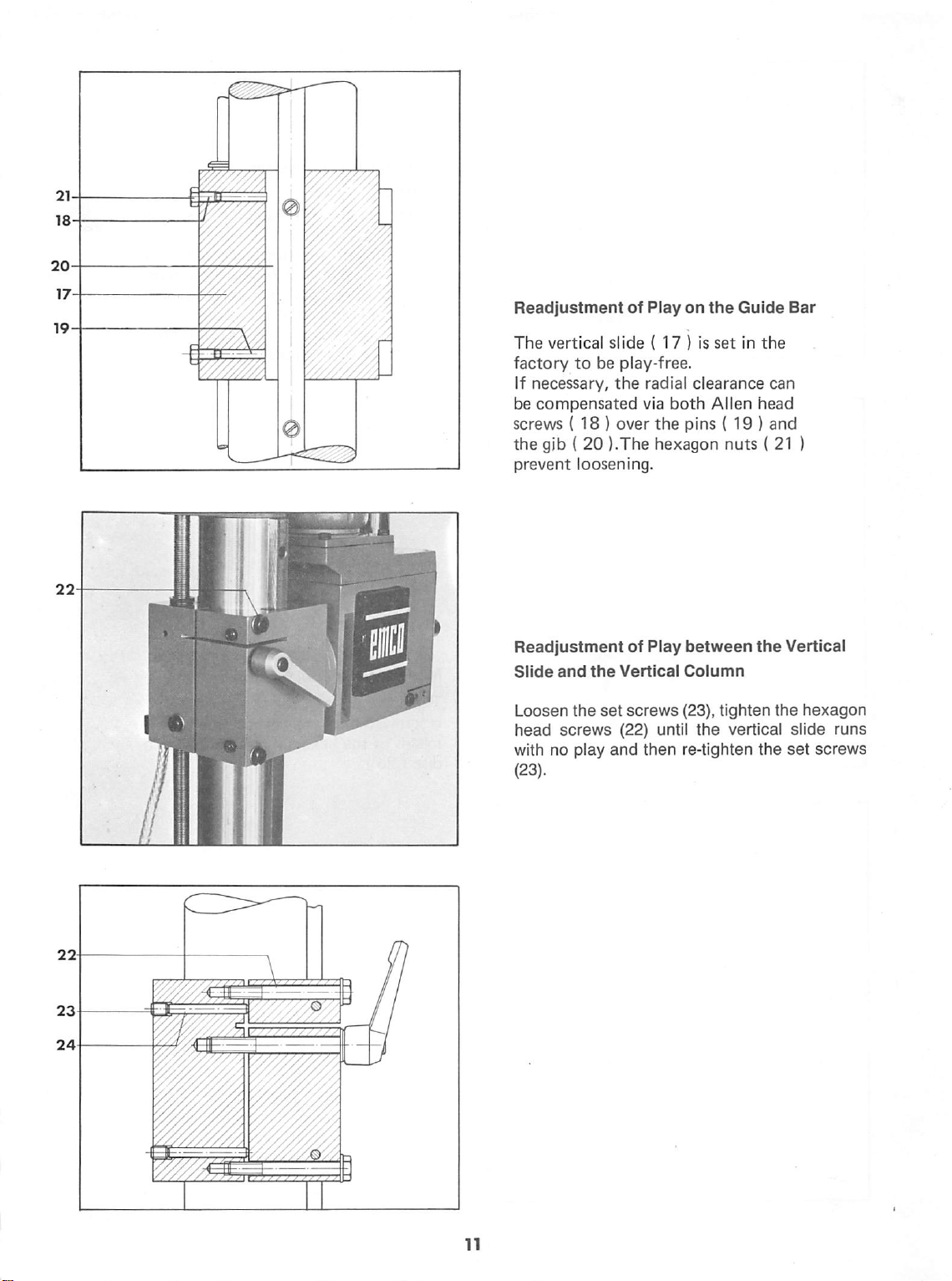
Readjustment
The
vertical
factory
If
necessary,
be
compensated
screws
the
gib ( 20
prevent
slide ( 17 ) Is
to
be
play-free.
the
(18)
over
).The
loosening.
of
Play
radial
via
both
the
hexagon
on
the
Guide
set
in
clearance
Allen
head
pins
(19)
nuts ( 21
Bar
the
can
and
)
Readjustment
Slide
and
the
Loosen
head
with
(23).
the
screws
no
play
set
(22)
and
of
Play
Vertical
screws
until
then
between
Column
(23),
the
re-tighten
the
tighten
vertical
the
Vertical
the
hexagon
slide
set
screws
runs
Page 14
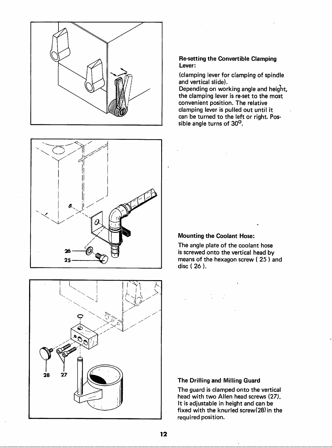
Re-setting
Lever;
(clamping
and
Depending
the
clamping
convenient
clamping
can
be
sible
the
lever
vertical
slide).
on
lever
position.
lever
turned
angle
turns
Convertible
to
for
clamping
working
is
of
angle
is
re-set
The
pulled
the
out
left
30°.
relative
or
Clamping
of
spindle
and
heiglit,
to
the
most
until
it
right.
Pos
Mounting
The
angle
is
screwed
means
disc ( 26).
The
The
head
It
fixed
required
of
the
Drilling
guard
with
is
adjustable
with
position.
the
Coolant
plate
of
onto
the
hexagon
and
is
clamped
two
Allen
in
the
knurled
Hose:
the
coolant
vertical
screw ( 25 ) and
Milling
height
Guard
onto
head
screws
and
screw(28)in
hose
head
the
vertical
can
by
(27).
be
the
12
Page 15
The
Slides
2 1
5
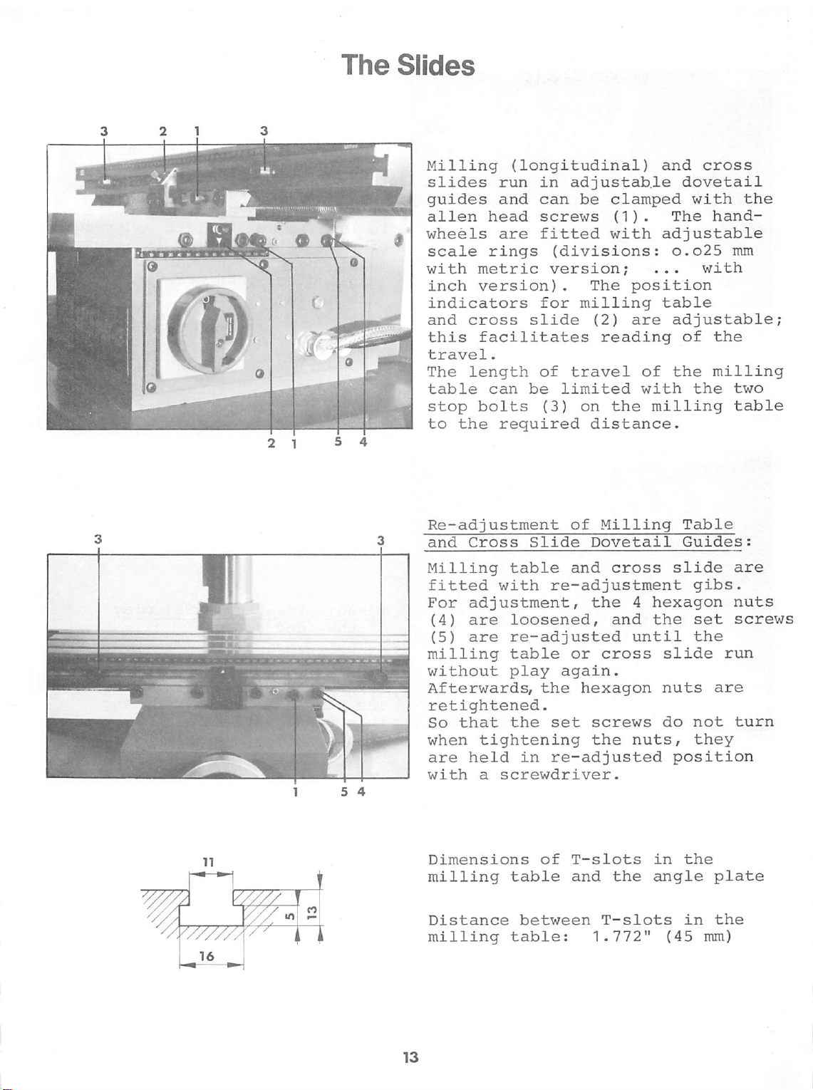
Milling
slides
guides
alien
wheels
scale
with
inch
indicators
and
this
travel.
The
table
stop
to
the
4
Re-adjustment
and
Milling
fitted
For
(4)
(5)
milling
without
Afterwards,
(longitudinal)
run
in
and
can
head
rings
metric
version)
cross
facilitates
length
can
bolts
are
screws
fitted
(divisions;
version;
.
for
slide
of
be
(3)
required
Cross
Slide
table
with
re-adjustment
adjustment,
are
loosened,
are
re-adjusted
table
play
the
adjustable
be
clamped
(1)
.
with
The
position
milling
(2)
are
reading
travel
limited
on
of
with
the
distance.
of
Milling
Dovetail
and
cross
the 4 hexagon
and
until
or
cross
again.
hexagon
and
cross
dovetail
with
The
hand-
adjustable
o.o25
.
..
with
table
adjustable;
of
the
the
milling
the
milling
Table
Guides:
slide
gibs.
the
set
the
slide
nuts
are
the
mm
two
table
are
nuts
screws
run
retightened.
So
that
when
are
with
the
tightening
held
in
a
screwdriver.
set
screws
the
nuts,
re-adjusted
do
not
they
position
turn
Dimensions
milling
Distance
milling
of
table
between
table:
T-slots
and
the
T-slots
1.772"
in
the
angle
in
(45
plate
the
mm)
Page 16
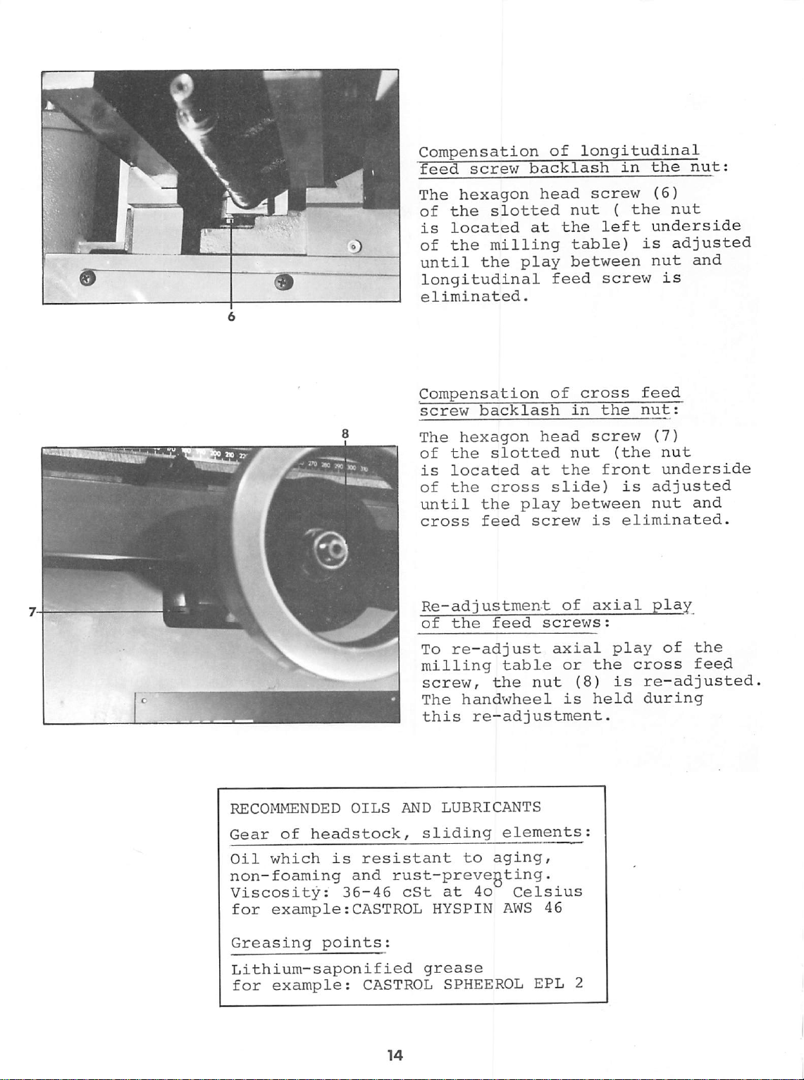
Compensation
feed
The
of
is
of
until
screw backlash
hexagon
the
slotted
located
the
milling
the
play
longitudinal
eliminated.
of
head
at
feed
longitudinal
in
screw
nut
(
the
the
left
table)
is
between
screw
the
nut:
(6)
nut
underside
adjusted
nut
and
is
Compensation
screw backlash
The
hexagon
of
the
slotted
is
located
of
the
until
cross
the
feed
at
cross
play
screw
Re-adjustment
of
the
feed
To
re-adjust
milling
screw,
The
this
table
the
nut
handwheel
re-adjustment.
of
in
head
nut
the
slide)
between
of
screws:
axial
or
(8)
is
cross
the
screw
(the
front
is
is
eliminated.
axial
play
the
is
held
feed
nut:
(7)
nut
underside
adjusted
nut
and
play
of
the
cross
feed
re-adjusted
during
RECOMMENDED
Gear
Oil
of
which
non-foaming
Viscosity:
for
example:CASTROL
Greasing
Lithium-saponified
for
example:
OILS
headstock,
is
resistant
and
36-46
points:
CASTROL
AND
LUBRICANTS
sliding
to
elements
aging,
rust-prevegting.
cSt
at
4o
Celsius
HYSPIN
grease
SPHEEROL
AWS
46
EPL
2
Page 17
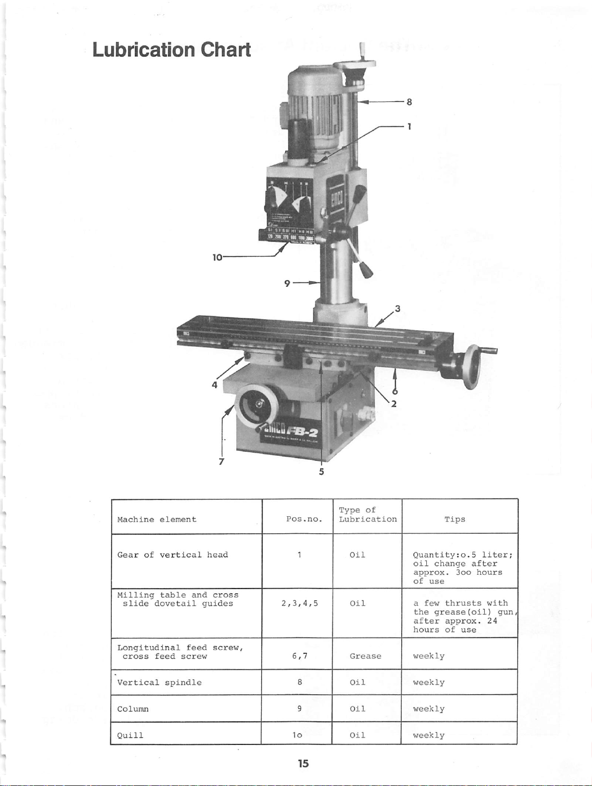
Lubrication
Chart
Machine
Gear
Milling
slide
element
of
vertical
table
dovetail
Longitudinal
cross
Vertical
Column
Quill
feed
spindle
feed
screw
and
head
cross
guides
screw
Pos.no
Type
of
Lubrication
Oil
Oil
Grease
Oil
Oil
;
1
Quantity:o.5
oil
change
approx.
of
use
a
few
the
grease(oil)
after
hours
weekly
weekly
weekly
Tips
after
3oo
thrusts
approx.
of
use
Liter;
hours
with
gun
24
Page 18
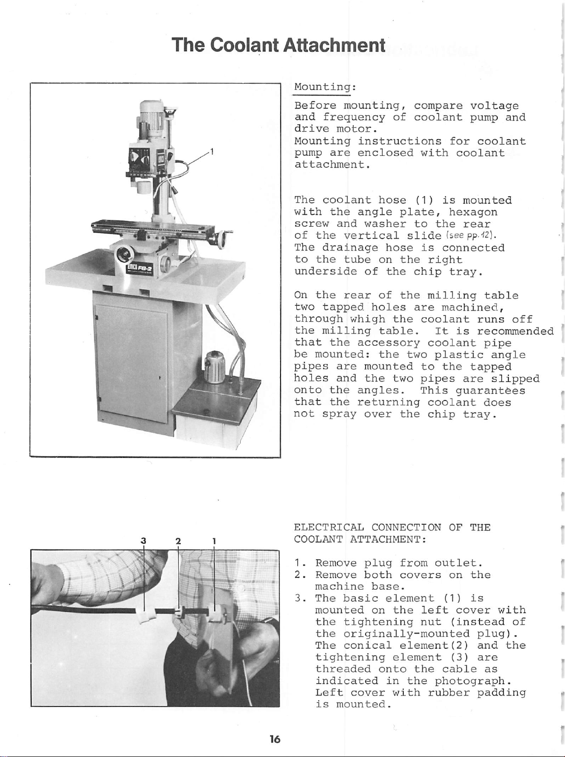
The
Coolant
Attachment
Mounting:
Before
and
drive
Mounting
pump
attachment.
The
with
screw
of
The
to
mounting,
frequency
motor.
are
coolant
the
and
the
vertical
drainage
the
tube
underside
On
the
rear
two
tapped
through
the
milling
that
be
pipes
holes
onto
that
not
the
mounted:
are
and
the
the
spray
of
instructions
enclosed
hose
angle
washer
plate,
slide
hose
on
the
of
the
of
the
holes
whigh
the
table.
accessory
the
two
mounted
the
two
angles.
returning
over
the
compare
coolant
for
with
(1)
coolant
is
hexagon
to
the
(see
is
connected
right
chip
tray.
milling
are
machined,
coolant
It
is
coolant
plastic
to
the
pipes
This
guarantees
coolant
chip
voltage
pump
mounted
rear
PP'
and
coolant
'^2).
table
runs
recommended
pipe
angle
tapped
are
slipped
does
tray.
off
ELECTRICAL
COOLANT
1.
Remove
2.
Remove
machine
3.
The
mounted
the
the
The
tightening
threaded
indicated
Left
is
CONNECTION
ATTACHMENT:
plug
both
basic
tightening
base.
element
on
the
from
covers
left
nut
outlet.
originally-mounted
conical
cover
mounted.
element(2)
element
onto
in
the
with
the
rubber
OF
THE
on
the
(1)
is
cover
(instead
plug)
and
(3)
are
cable
as
photograph.
padding
with
of
.
the
Page 19
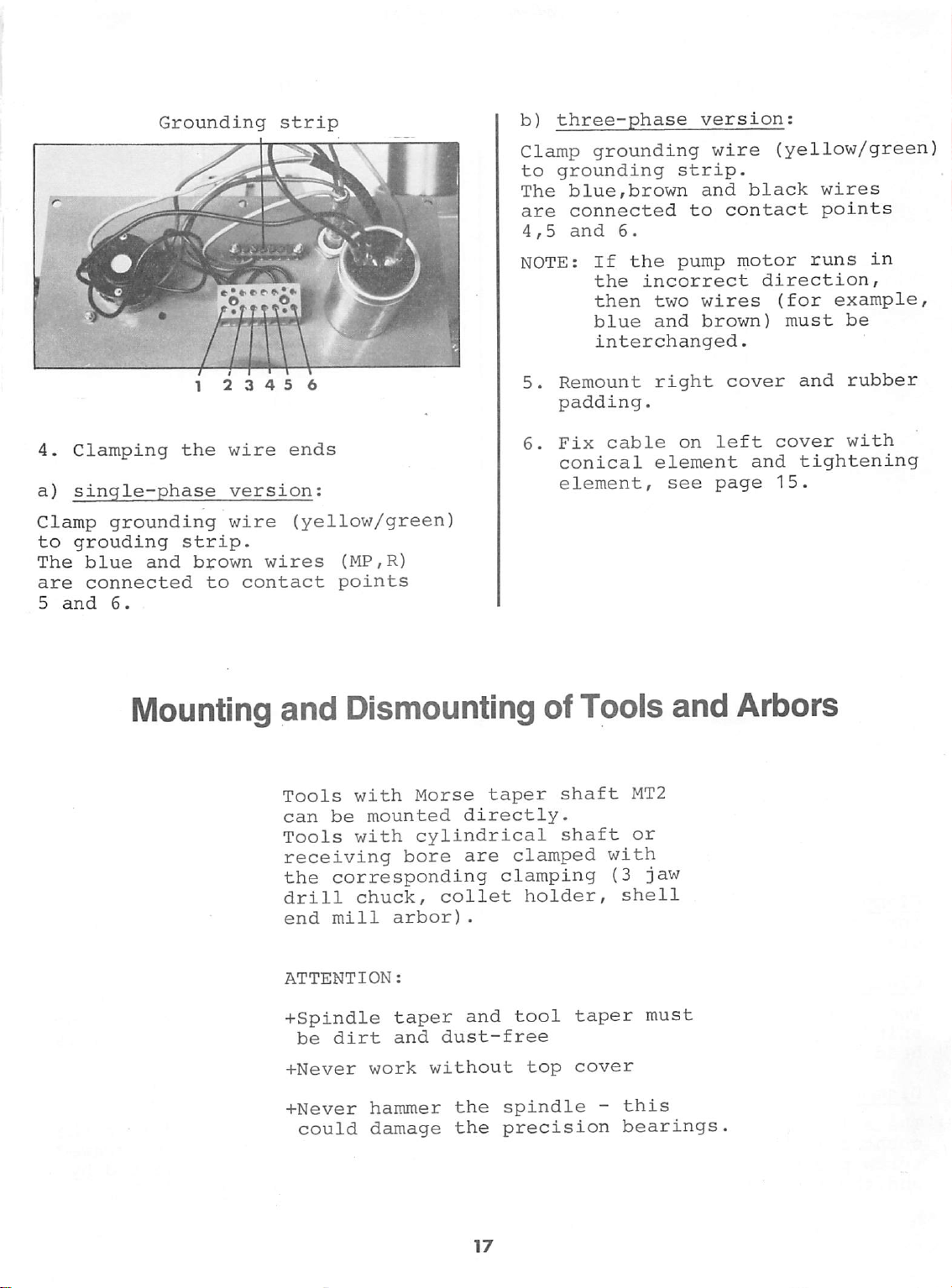
Grounding
strip
b)
three-phase
version;
4.
Clamping
a)
single-phase
Clamp
to
The
are
5
grounding
grouding
blue
connected
and
6.
1 2 3 4 5 6
the
strip.
and
brown
wire
version;
wire
to
contact
ends
(yellow/green)
wires
(MP,R)
points
Clamp
to
grounding
The
blue,brown
are
connected
4,5
and
NOTE:
5.
Remount
padding.
6.
Fix
conical
element,
grounding
strip.
and
to
6.
If
the
pump
the
incorrect
then
blue
interchanged.
cable
two
wires
and
brown)
right
on
element
see
wire
black
contact
motor
direction,
cover
left
and
page
(yellow/green
wires
points
runs
(for
must
and
cover
tightening
15.
in
example,
be
rubber
with
Mounting
and
Tools
can
Tools
receiving
the
drill
end
ATTENTION:
+Spindle
be
+Never
+Never
could
Dismounting
with
be
with
corresponding
chuck,
mill
dirt
Morse
mounted
cylindrical
bore
arbor)
taper
and
work
hammer
without
damage
taper
directly.
are
collet
.
and
dust-free
the
the
of
clamped
clamping
holder,
tool
top
spindle
precision
Tools
shaft
shaft
taper
cover
MT2
or
with
(3
jaw
shell
must
-
this
bearings
and
Arbors
Page 20
JZl
i
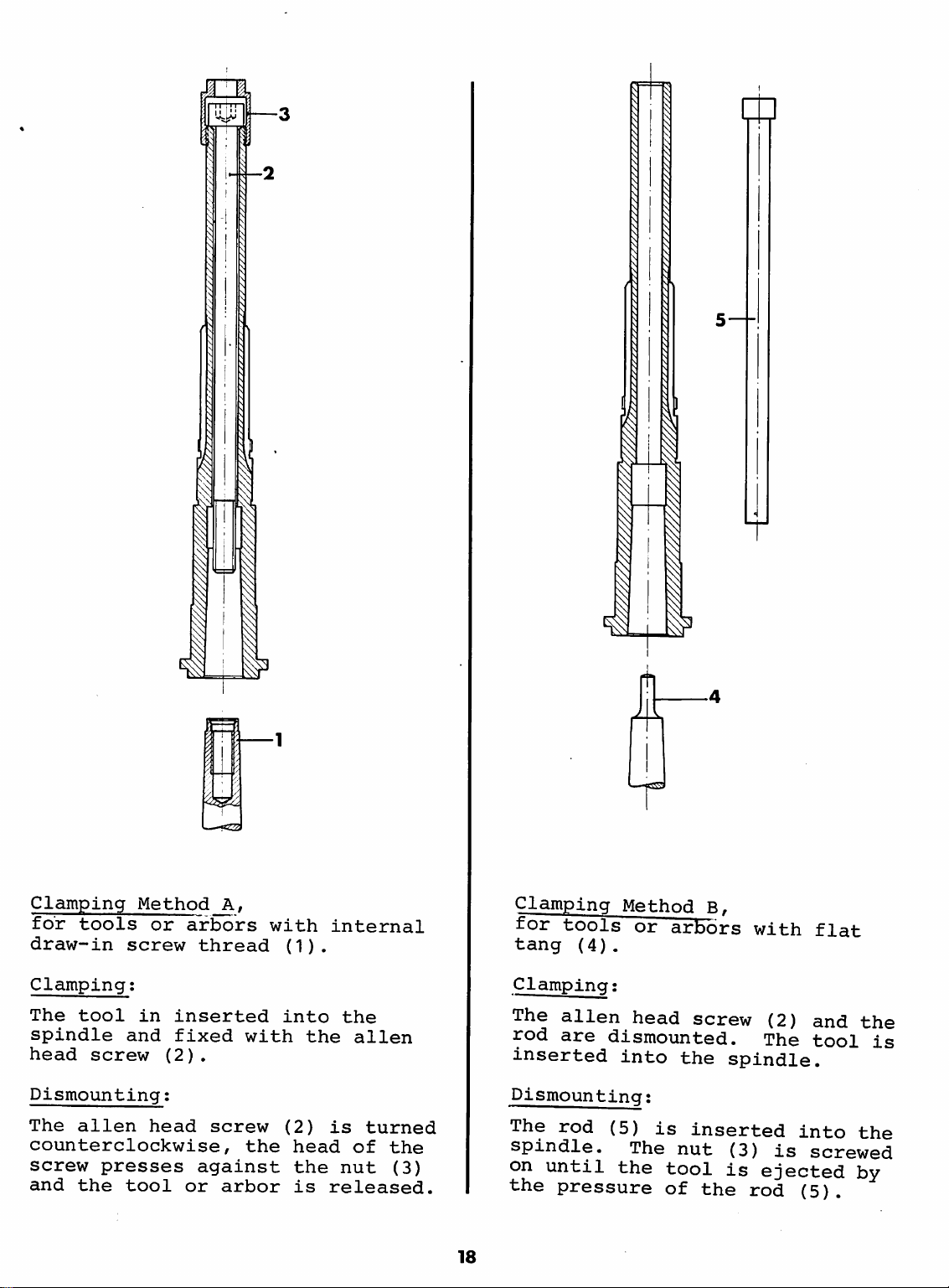
Clamping
for
tools
draw-in
Clamping;
The
tool
spindle
head
Dismounting:
The
alien
counterclockwise,
screw
and
the
Method_A,
screw
in
and
screw
presses
tool
or
arbors
inserted
fixed
(2)
.
head
against
or
thread
with
screw
the
arbor
with
(1).
into
the
(2)
head
the
is
internal
the
alien
is
turned
of
the
nut
(3)
released.
18
Clamping
for
tools
tang
Clamping:
The
alien
rod
are
inserted
Dismounting:
The
rod
Method
(4).
dismounted.
into
(5)
spindle.
on
until
the
pressure
the
or
arbors
head
is
The
nut
tool
of
B,
with
screw
(2)
The
the
spindle.
inserted
(3)
is
ejected
the
rod
into
is
screwed
(5).
flat
and
the
tool
the
by
is
Page 21
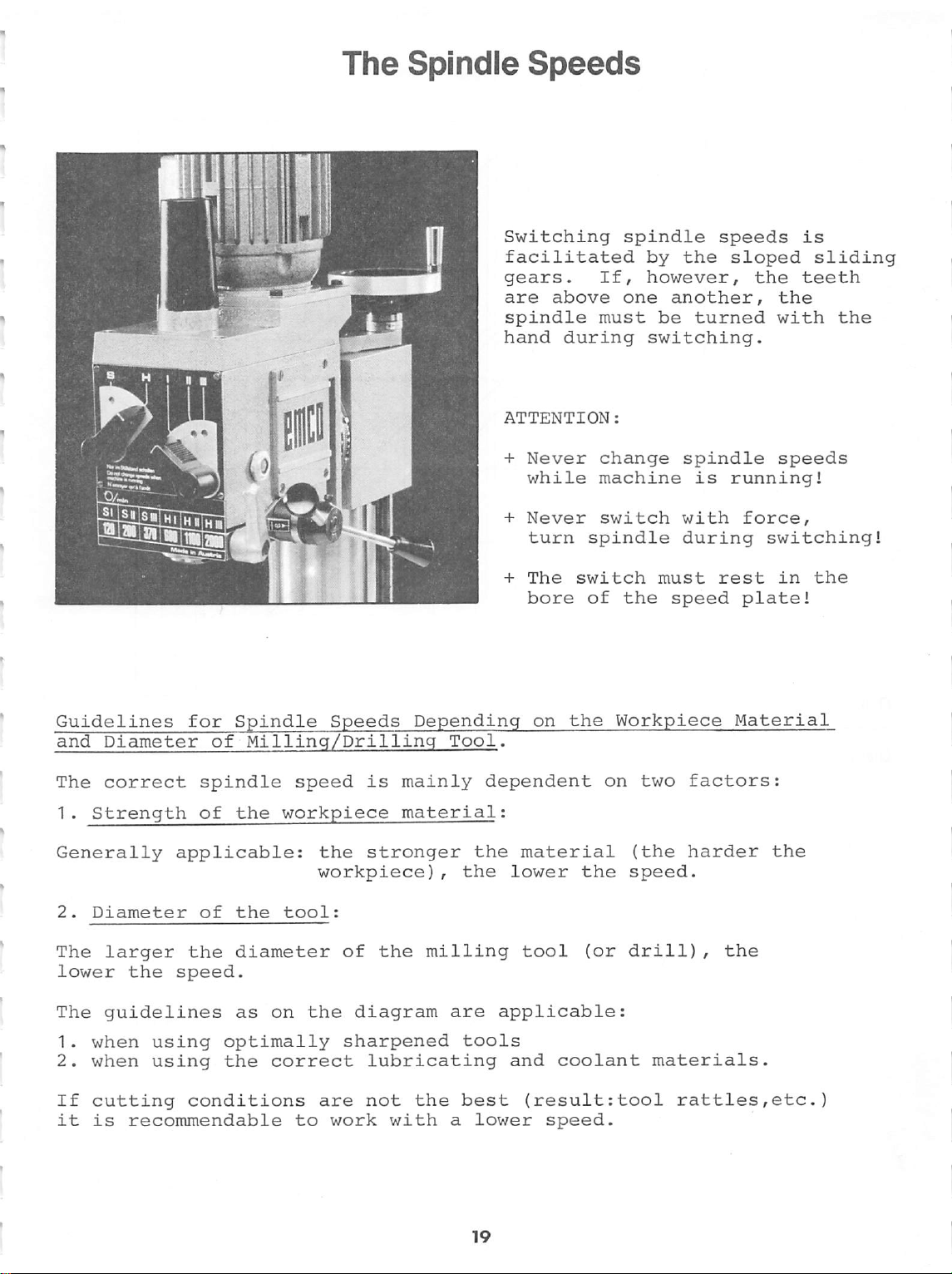
The
Spindle
Speeds
mssmr-
j
Switching
facilitated
gears.
are
spindle
hand
ATTENTION:
+
Never
while
+
Never
turn
+
The
bore
If,
above
must
during
change
machine
switch
spindle
switch
of
spindle
by
the
however,
one
another,
be
switching.
spindle
with
during
must
the
speed
speeds
sloped
turned
is
running!
force,
rest
plate!
is
sliding
the
teeth
the
with
speeds
switching!
in
the
the
Guidelines
and
Diameter
The
correct
1.
Strength
Generally
2.
Diameter
The
larger
lower
The
1.
2.
If
it
the
guidelines
when
when
cutting
is
recommendable
for
Spindle
of
spindle
of
the
applicable:
of
the
the
diameter
speed.
as
using
using
optimally sharpened
the
conditions
Speeds
Milling/Drilling
speed
is
workpiece
the
stronger
workpiece)
tool:
of
the
on
the
diagram
correct
to
lubricating
are
not
work
with a lower
Depending
Tool.
mainly
material:
the
,
the
milling
are
tools
the
best
on
the
dependent
material
lower
tool
applicable:
and
the
(or
coolant
(result:tool
speed.
Workpiece
on
two
(the
speed.
drill),
materials.
rattles,etc.)
Material
factors:
harder
the
the
Page 22

E
a
</>
•o
V
0)
Q.
to
-2400
■D
-
2C00
—445
-240
-200
Diameter
Diameter
of
tool
(mm)
of
tool
(inch)
Example;
Workpiece
Diameter
One
of
The
follows
approx.
selected
theoretical
In
this
0,1"
material:
of
case
milling
the
14oo
speed
speed.
11oo
7 8 9
0,25"
broken
rpm.
must
rpm.
10
12
Aluminum
tool:
line
always
1.6
alloy
and
III
inch
be
30
comes
under
U)
50 60
2"
to
a
60
100
3"
speed
4"
the
20
Page 23

Clamping
Devices
for
Tools
—Y
CLAMPING
AND
COLLETS
Clamping
The
collet
with
round
1.
Collet
E
25
Collets
For
clamping
the
appropriate
Clamping
engraved
E
25
collets,
The
clamping
while
2.
Collet
ESX
25
(available
The
collets
greater
When
are
drawn
annular
The
collets
No.
225
WITH
Method
holder
shanks
Holder
range: h 13.
on
see
counterforce
Holder
Collets
from
of
clamping
the
clamping
off
ring
round
are
000)
THE
A
enables
and
of
(Order
with
collets
collet
the
collet. - For
the
brochure.
nut
is
tightened
is
exerted
(Order
mid-1981)
Type
ESX
ranges
nut
the
cone
the
collet
available
or
separately.
COLLET
HOLDER
clamping
drills.
No.
721
of
Type E 25,
for
each
The
clamping
the
with a hook
with
No.
520
25
enable
(see
table).
is
unscrewed,
of
the
collet
waist.
either
as a set
of
milling
000)
shank
diameter
Order
the
key
000)
you
holder
of
tools
for
Type
you
need
diameter.
is
Nos.
of
the
spanner
wrench.
for
Type
to
bridge
the
collets
by
the
14
(Order
Nominal
2,0
2,5
3,0
4,0
5,0
6,0
7,0
8,0
9,0
10,0
11,0
12,0
13,0
14,0
diameter
in
mm
individual
Chucking
capacity
1,5-2,0
2,0-2,5
2,5-3,0
3,0-4,0
4,0-5,0
5,0-6,0
6,0-7,0
7,0-8,0
8,0-9,0
9,0-10,0
10,0-11,0
11,0-12,0
12,0-13,0
13,0-14,0
collets
in
mm
ESX-25
Chucking
capacity
'As-Vm
^35
'/64
Va-yM-ya?
"/64-3A8
'%4-'/33-'Vm
'A-"/64
8/3J-
I9/»4-5As
3V64-"/32
33/(M-3/g_35/54
'V32-"/<14
Vi6-3»/64-IV3J
31/64-Vj
33/64-IV33-35/64
in
inches
The
using
it
can
the
milling
the
Spare
Order
No.
225
020
225
025
225
030
225
040
225
050
225
060
225
070
225
080
225
090
225
100
225
110
225120
225130
225140
21
machine
the
T-slot
also
be
table.
Parts
Important
Collets
721
into
vice
is
fitted
screws.
clamped
For
On
onto
the
List.
Note:
of
Type
000.
However,
collet
holder
onto
the
Maximat
the
screw
ESX
25
collets
520
000.
the
cross
slide
Super
angled
dimensions,
can
be
of
11,
plate
and
see
used
in
Type E 25
collet
holder
do
not
fit
Page 24

CLAMPING
IN
THE
DRILL
CHUCK
Clamping
Necessary
* 3 jaw
*
Morse
Drills
(13
Method
accessories:
drill
taper
with
mm)
can
for
Drill
chuck
cylindrical
be
with
arbor
MT2
diameter
clamped
key
in
Chuck:
(1)
(2)
of
the 3 jaw
B
up
to
drill
0.52"
chuck.
HI
kuuuuwuuuiil
w
CLAMPING
Clamping
Necessary
*
shell
*
special
*
Set
spacing
spacing
spacing
spacing
Tools
(milling
cutters,
against
over
clamping
The
Method A (for
accessories:
end
key
of 4 collars
collar 4 mm
col
collar 8 mm
col
with a receiving
cutters,
circular
the
collar
the
spacing
screw
special
IN
THE
mill
arbor
(2)
lar 6 mm
lar
12
staggered
saw
of
collars
(7).
key
(2)
SHELL
shell
(1)
(3)
(4)
(5)
mm
(6)
bore
of
tooth
blades)
the
are
shell
(3,4,5,6)
is
used
for
END
end
16
mill
mm
side
milling
MILL
arbor)
diameter
clamped
end
mill
arbor
with
the
tightening.
ARBOR
2—
22
Page 25

BORING
AND
FACING
HEAD
(FLY
CUTTER)
58
mm
58 - llo
Technical
On
the
are
Toolholder
Smallest
Largest
Toolholder
Smallest
Largest
Dimensions
Scale
Working
Before
with
0
12
mm
Adjusting
—
Adjustment
done
—
mm
By
Data:
slide
two
machined.
in
left
diameter:
diameter:
in
right
diameter:
diameter:
of
turning
divisions:
tip:
machining,
the
set
screw
tips:
with
the
adjusting
backlash
of
bores
of
12
bore:
20
mm
(0.8")
58
mm
(2.3")
bore:
58
mm
(2.3")
110
mm
(4.4")
tools:
0.025
mm
clamp
(17).
of
playfree
set
the
leadscrew
the
guidance
screws
set
screw
is
mm
(0.5")
6x6
cross
dia.
mm
(V4" x V4")
slide
is
(18).
(4)
the
eliminated.
Heavy-duty
8
mm
cylindrical
Clampingrwith
Dovetail
dia. X 60°
12
mm
Clamping:with
taper
dia.
for
shaft;
attachment
milling
with
dia.
attachment
roughing
collet
cylindrical
collet
shank
end
cut,
chuck
cutter,
16
chuck
mill,
mm
shaft
All
Tools
Tools
of
HSS
Quality
Heavy-duty
15
mm
dia.,
Morse
taper
Clamping:direct
ding
Two
flute
slot
cal
shaft,
3,4,5,6
Clamping:with
attachment
taper
for
roughing
MT2;
clamping
to
drill
mm
collet
shank
end
Method
with
cylindri
dia.
chuck
mill,
cut,
accor
A
23
Page 26

Twist
drills,
1-
13
mm
1
set
consists
Clamping:
HSS,
in
steps
of
with
collet
DIN
of
25
pieces
drill
chuck
338
1/2
mm,
chuck
attachment
or
T—slot
cylindrical
T—slot
cylindrical
Clamping:
cutter,
shank,
cutter
shank,
with
12,5
mm
TO
mm
16
mm
10
mm
collet
attachment
dia. x 6
dia. x 8
chuck
mm
mm
Heavy-duty
roughing/finishing,
width
Clamping:
Circular
dia.
of
bore
16
Clamping:
20
mm,
saw
blade
mm.
shell
end
dia.
with
shell
blade,
60
mm,
with
shell
mill,
outside
of
bore
end
fine
tooth,
width
end
with
dia.
40
16
mm.
mill
0,8
mill
spiral
for
mm,
arbor
mm,
arbor
Staggered
dia.
bore
Staggered
outside
bore
of
cutter
16
16
tooth
mm
tooth
dia.
mm
Clamping:
Gear
milling
pressure,
module
module
module
bore
0,5
1
1,25
side
milling
35
mm,
width 5 mm,
side
milling
50
mm,
width 6 mm,
with
shell
end
o
cutters,
16
relieved
mm
available
pieces
or
cutter,
cutter,
mill
arbor
for
20°
in
set
of
8
individually
24
Page 27

Clamping
Devices
for
Workpieces
CLAMPING
CLAMPING
Clamping
WITH
SHOES
height:
Large-surfaced
clamped
the
Depending
workpiece,
shoes
clamp
CLAMPING
CHUCK
Necessary
to
stepped
are
the
WITH
125
the
clamping
on
the
two
necessary
workpiece
mm
dia.
accessories:
THE
STEPPED
2.36"
workpieces
cross
slide
shoes.
shape
or
more
in
securely.
THE
LATHE
{60
mm)
can
with
of
the
clamping
order
to
be
+
Lathe
+
Adaptor
The 3 bolts
lathe
threaded
mounted
with
Depending
ments,
chuck
table
NOTE:
The
with
stepped
chuck
chuck
to
the
the
is
or
lathe
one
jaws
125 ram
plate
are
with
ends.
the
hexagon
on
the
adaptor
mounted
the
angle
chuck
set
of
and
adaptor
externally-stepped
When
note
in
groove
changing
that
groove
no.2,
jaws,
jaw
no.1
no.1,
etc.
dia.
put
into
the
short
The
chuck
plate
nuts.
work
on
is
internally-
one
require
plate
the
plate.
equipped
set
jaws.
one
is
placed
jaw
no.2
the
is
with
milling
of
must
in
Page 28

CLAMPING
WITH
THE
MACHINE
VICE
Width
of
Clamping
The
machine
the
milling
using
THE
VICE
The
the
the
SWIVEL
swivel
milling
bolts,
The
base
milling
guide
pins,
T-slots
jaws:
capacityiup
vice
table
two
T-nut
BASE
base
table
washers
is
positioned
table
by
which
of
the
3.3o"
(Bo
is
clamped
or
bolts.
FOR
THE
is
mounted
with
and
hexagon
means
fit
milling
(84
to
3.15"
mm)
angle
MACHINE
4
T-nut
on
of
into
table.
mm)
to
plate
to
nuts.
the
2
the
The
machine
base
bolts
The
the
NOTE:
The
contact
machine
when
Scribing
machine
The
so
and
and
machine
centering
centering
mounting.
machine
that
parallell
slide.
zero-mark
vice
The
with
with
with
positioning
the
an
spindle
vice
fixed
hexagon
vice
surfaces
vice
vice
the
must
Zero-mark
vice
the
fix
to
the
In
this
is
made
a
scriber.
aid
of a dial
arbor
taper.
is
with
nuts.
is
ring.
ring
and
of
be
is
clamping
longitudinal
position,
on
itself
inserted
placed
the 2
centered
the
dust-free
all
base
on
on
T-nut
other
the
positioned
jaw
the
the
machine
is
done
gauge
in
the
the
with
and
is
or
Page 29

THE
ANGLE
PLATE
Clamping
Distance
Workpieces
directly
shoes
vice,
attachment
chuck.
or
lathe chuck
surface:
of
T-slots:
can
be
with
with
with
the
the
mounted
6.9"x5.5"
(175
( 9omm)
x14o
3.54"
clamped
clamping
machine
or
dividing
mm;
lathe
Page 30

The
Dividing
Attachment
TECHNICAL
Diameter
Worm
reduction
T-slots
standard
Number
plates:
Necessary
clamping
the
lathe
dividing
+
Dividing
+
Adaptor
+
Lathe
OPERATING
DATA
of
rotary
according
of
holes
accessories
the
workpieces
chuck
attachment:
attachment
plate
chuck
ELEMENTS
table:
to
in
dividing
27,33,34,36,
38,39,4o,42
on
the
125
mm
(15o
1 : 4o
factory
for
in
dia.
6"
mm)
Clamping
table
f1)
Clamping
during
itself,
before
Indexina
Duging
15
the
rotary
the
but
every
digect
to
15 , the
parameter
table.
dividing
free
dividing
graduated
must
to
The
controlling
Crank
plunger
which
wheel
indirect
be
pulled
the
left.
graduated
handle
(4)
is
of
levers
:
levers
dividing
must
machining
oin
with
dividing
notches
During
(worm
by
scale,
scale
the
with
move
engaged
the
rotary
dividing.
for
rotary
are
loosened
operation
be
clamped
handle
pin
rests
of
indirect
dividing)
means
the
indexing
out
and
(3)
divisions.
index
the
worm
with
the
table
operation.
(2):
from
into
the
or
of
the
pin
swivelled
for
wormduring
The
shears
adding
a
fraction
added.
the
serve
number
of
a
to
of
turn
facilitate
holes
is
to
when
be
Page 31

T-slots
of
the
10,5
Dividing
Attachment
:S
OF
Disengaging
The
alien
loosened.
is
turned
worm
The
hand
By
and
rotary
for
turning
clockwise,
are
engaged.
engagement
the
rotary
slightly
The
alien
again
be
operation.
DIVIDING
and
Engaging
head
counterclockwise,
wormwheel
direct
by
head
tightened
screw
When
table
the
dividing
worm
To
of
worm
table
hand.
screw
the
dividing
are
can
indexing.
and
wormwheel
facilitate
and
should
after
the
(5)
is
disengaged.
be
turned
plate
wormwheel,
be
moved
(5)
must
this
Worm:
plate
the
by
Xr
4o times,
makes
With
plates,
turns
1
revolution
help
exact
can
the
of
the
be
executed.
rotary
(36o ).
dividing
fractions
The
1st
2nd
3rd
4th
tagie"
of
Indexing
column
column
column
column:
Direct
Worm
engaged.
Possibility
dividing
indexing
possibility
(i.e.,
within
Possibility
The
freely
graduated
table.
Table:
indicates
of
divisions
36o
shows
ing
division
shogs
36o
revolutions
are
shows
holes
for
the
angle
the
crank
necessary
the
to
each
Dividing:
and
wormwheel
by
pin
maximum
36o
dividing
with
number
per
correspond
of
the
number
handle
which
number
be
added
index
plate
1:
means
(2).
from
).
2:
can
the
scale
of
of
15
of
be
aid
on
of
24
are
dis
the
gividing
to
15
divisions
done
of
the
the
rotary
29
Page 32

30
30
12°
1
9
11
12
13
14
20'
1
28
1
18
■>
(0
175°
19
12
33
1
7
2
180°
20
32
1
9
10
Q
Q}
CT
27
33
34
36
38
39
O
.(C
o
m
jiC
for
Amount
each
of
index
holes
plate
to
be
added
40
42
a
M
>
^
°
^
O)
zB
27
33
34
36
38
39
40
42
o
g
2V
CT3
for
Amount
each
of
Index
holes
plate
to
be
added
O(
o
o
Worm
n
=
No.
reduction
of
revoiutions
NDEXTABLE
z
K
=
=
No.
of
No.
the
of
of
divisions
workpiece.
revolutions
of
dividing
of
handle
head
for
1:40;
one
i.
dividing
e.
required
of
handie
for
one
for
a
revolution
complete
K
=
40.
move:
of
revolution
the
workpiece
n
=
-^
Formula
for
the
Calculation
of
the
Hole
Numbers
Required
10
11
12
25°
2
21
84
20
80
17
18
19
20
14
2
36
21
78
13
3
3
20
3 9
11
12
13
14
76
20
MC
OC
CO
MC
CM
ni
O
CM
O
O
72
5°
15
o
o
o
20
o
o
o
3
21
36°
4
70
24
9
40°
4
12 16
68
20
8
45°
5
66
20
50°
5
15
65
24
64
30
25
65°
7
6
55
24
70°
7
21
54
20
5
8
52
30
6
7
60°
55°
6
5
6
18
3
22
24
26
28
56
60
6°
18
«
30
75°
8
9
11
12
13
14
7«
21
28
50
8
24
32
4
10
48
30
35
100°
11
3
45
8°
24
32
110°
12
6
44
30
3
120°
13
9
11
12
13
14
42
40
13
24
40
9°
1
130°
14 12
39
OC
o
1
1
140°
15
15
38
1
2
150°
16
18
36
10°
1
3
4
160°
17
21
35
1
6
170°
18
24
34
1
6
22
24
26
27
25
1
27
200
8
1
38
180
2°
6
8
16°
1
21
120
3°
9
11
12
13
14
15°
1
1
1
1
13
40'
2
2
21
360
1°
3
24
270
4
18
22 24
26 28
240
6
7
18°
2
100
16
19
96
15
18
2
2
6
8
4
95
16
20
21
17
2
12
90
4°
12
16
16
88
15
2
17 18
19
20
21
15
2
18
22 24
26
28
85
16
Page 33

EXAMPLE
OPERATION;
OF
AN
INDIRECT
DIVIDING
Practical
1.
The
holes
Execution:
indexing
is
mounted.
Desired
From
be
seen
division
must
turn
the
indexing
plate
division:
the
Indexing
that
at
the
13, 3 full
be
made
of 3 additional
plus a fraction
plate
with
39
13
divisions
in
36o"
Table
desired
crank
holes
39.
it
can
turns
on
Execution
Operation:
3
full
tional
holes
that
in
One
are
the
the
dividing
completed.
of
turns
turn
made;
plunger
black
the
Dividing
plus
of
the
the
that
is
hole.
operation
frac
3
added
means
placed
is
In
Indexing
that
holes
Therefore,
fixed
4
3.
The
placed
39
drawing)
arm
the
the 4 th
at
have
so
holes.
indexing
in a hole
(marked
moved
pin
column
Table,
the
to
the
that
black
and
until
of
the
one
39
plate,
be
shears
they
plunger
the
it
plunger.
of
sees
added.
include
of
the
on
the
left
touches
the
3
are
is
shear
5.
Next
The
the
pin
operation
cribed
NOTE:
The
shears
during
otherwise
their
tation
Dividing
shears
left
arm
again;
in
may
the
dividing
they
purpose
aid.
Operation:
are
turned
touches
the
next
follows
4.
above.
not
do
as
an
the
dividing
as
des
be
moved
operation,
not
serve
orien
until
31
Page 34

Circuit
Diagram
single
^
phase
FB-2
V-®
A
m1
b1
Motor
k 1 Condenser
m1
Motor
L1
Connection
switch
k1
strip
LI
6i
02^3
O5
60
33
Page 35

Circuit
Diagram
LI
)
)
)
>—
)
>—J
three
"
►
phase
FB-
2
R
o
*1
\
<
S
o
i
o
6
T
SI
o-
J
U2>.
W2
U2
V2
§§§
U'1
V1
b1
ml
LI
A
or Y connection
Motor
Motor
Connection
switch
see
strip
Motor
V2 J W2
capacity
6
vi
W2
o o
Plate
U2
^2
o
W>1
34
Page 36

Page 37

Page 38

Page 39

Pos
1
2
3
4
5
6
7
8
9
10
11
12
13
14
15
16
17
18
19
20
21
22
23
24
25
26
27
28
29
30
31
32
33
34
35
36
37
38
39
40
41
42
43
44
45
46
F2A
F2A
F2A
F2A
F2A
F2B
F2A
F2A
F2B
F2A
F2B
F2A
F2B
F2A
F2A
F2A
F2A
F2A
F2A
D1A
D1B
F2A
F2A
F2A
F2A
F2A
B4A
B2A
B2A
D1Z
ZLG
ZSR
ZRG
ZFD
H4A
ZMU
ZSR
ZSR
ZSR
ZSR
ZSR
ZST
ZST
ZST
ZSR
ZSR
ZMU
ZSB
ZSR
ZFD
ZSB
Ref.
000
000 020
000
000
000
000 050
000
000
000
000 090
000
000
000
000
000
000
000
000150
000
020
020 070
000
000190
000
000
000
040
000
013
250
62
12
72
88
000
85
98
12
33
12
40
72
13
51
12
12
36
25
84
85
25
Nr.
010
030
040
050
060
070
070
090
100
100
110
120
130
140
160
070
180
200
210
220
011
080
000
060
0001
0616
3012
0337
300
1000
0003
0830
0625
1070
1030
0628
0616
0816
0816
0820
0800
0530
0510
4412
0640
DIN
M6x16DIN912-6.9
30x1,2
01N472
3x3,7
DIN
6888
M10DiN985-6
1,47x6,35
M8X30DIN912-6.9
M6x25DIN933-5.6
Ml
M10x30t)IN939-8.8
6x28DIN1472-6.8
M6X16DIN913-45H
M8x16DIN551-5.8
M8x16DIN912-6.9
M8x20DIN912-6.9
M8
B5,3
M5x10DIN84-4.8
A4x4x12DIN6885
B6,4
0x70
DIN
DIN
DIN
TYP
LL
DIN912-6.9
936-6
125
125
Benennung
Frastisch
Schlitten
Sockel
Saulantrager
Mutter
metr.
Mutter
USA
Spindeltr^er
Skalenring
Skalenring
Langsspindel
Langsspindel
Querspindel
Querspindel
Anschlag
Anschlagbolzen
Klemmschraube
Nachstelleiste
Nachstelleiste
Posltionsschild
Schild
Schild
Deckblech
Druckbolzen
Druckbolzen
Abstreifblech
Abstreiffilz
Handrad
Bogenfeder
G.
T-Nutenstein
Rillenkugellager
Zylinderschraube
Sicherungsring
Scheibenfeder
Zwischenring
Sechskantmutter
Hammerschraube
Zylinderschraube
Sechskantschraube
Zylinderschraube
Stiftschraube
PaBkerbstift
Gewindestift
Gewindestift
Zylinderschraube
Zylinderschraube
Sechskantmutter
Scheibe
Zylinderschraube
PaBfeder
Scheibe
metr.
USA
metr.
USA
metr.
USA
metr.
USA
1
2
100
Kegelgriff
Description
Milling
table
Slide
Pedestal
Column
support
Nut
metr.
Nut
USA
Screw
mount
Graduated
Graduated
Longitudinal
metr.
Longitudinal
USA
Cross
Cross
Stop
Bolt
Clamping
Gib
Gib
Setting
Scale
Scale
Cover
Adjusting
Adjusting
Wiper
Felt
Handwheel
Feed
Handle
T-nut
Ball
Allen
Circlip
Woodruff
Spacer
Hexagon
Screw
Allen
Hexagon
Allen
Stud
Grooved
Set
Set
Allen
Allen
Hexagon
Washer
Flat
Key
Washer
feed
feed
mark
mark
mark
sheet
plate
wiper
spring
bearing
head
head
head
screw
screw
head
head
head
ring
metr.
ring
USA
feed
feed
screw
screw
screw
metr.
USA
pin
1
pin
2
screw
key
nut
screw
head
screw
screw
adjusting
screw
screw
nut
screw
screw
screw
metr.
USA
pin
Designation
Table
de
fraisage
Chariot
Socle
support
Support-colonne
Ecrou
metr.
Ecrou
USA
Porte-broche
Bague
gradu^e
metr.
Bague
graduee
USA
Vis
filetle
longitudinale
Vis
filet§e
longitudinale
Vis
filetee
transversale
Vis
filet^e
transversale
Butee
Tige
de
butee
Vis
de
serr'age
Lardon
de
reglage
Lardon
de
reglage
Plaque
de
position
Echelle
metr.
Echelle
USA
Tole
de
protection
Boulon
de
pression
Boulon
de
pression
Plaquette
Racleur
Volant
Ressort
Levier
Ecrou
Roulement a bllles
Vis 6 pans
Anneau
Clavette
Douille
Ecrou 6 pans
Vis
Vis 6 pans
Vis
Vis 6 pans
Goujon
Cheville
Vis
Vis
Vis 6 pans
Vis 6 pans
Ecrou 6 pans
Rondelle
Vis
Clavette
Rondelle
de
en
feutre
arque
spherique
en
T
creux
de
retenue
d'&artement
creux
hexagonale
creux
de
posit
pointeau
pointeau
creux
creux
tete
cylindrique
racleur
metr.
USA
metr.
USA
1
2
postSrieur
post§rieur
Page 40

Pos
47
48
49
50
51
52
53
54
55
56
57
58
59
61
62
63
64
65
66
67
68
69
70
71
72
73
74
75
76
/7
/8
.'M
Ref.
ZKG
ZST
ZNP
ZDK
F2A
F2A
F2B
F2A
F2B
F2A
ZMU
ZSB
ZSB
ZSB
ZSB
F2H
F2A
F2A
ZPG
ZPG
ZPG
ZPG
ZDK
ZSR
ZRG
ZMU
ZKO
ZEL
ZEL
ZEL
ZEL
ZEL
F2A
ZSR
ZEL
ZSR
ZRG
ZMU
ZDK
F2A
ZEL
Nr.
00
1060
11
0632
01
2000
60
0012
000
000
000
000
000
000
341000
251050
12
1001
121002
121003
100
100
100
10
0008
10
0007
20
1100
20
1350
60
0018
83
0416
28
0040
34
0401
26
0020
26
0030
26
3222
26
1221
26
3381
100
89
0510
01
0005
83
0325
28
0030
34
0300
60
0004
100
40
0002
270
240
240
250
250
230
020
020
030
040
010
'
DIN
6,0GK3DIN5401
6h11x32
INA
M10
B10,5
10x16x0,1
10x16x0,2
10x16x0,3
MZ
MZ
PG
PG
M4x16
B4
M4
M5X10DIN7985-
A
4.0
Bk6
M3x20
83
M3
Kapsto
B13
B11
11
13,5
DIN
DIN934
Q
KrG
DIN
DIN
NIP
DIN
DIN
DIN84-4.8
127
DIN84-4.8
127
934-5
F4
DIN
A2
934-6
125
Benennung
Stahlkugal
7
Zylinderstift
Schmiernippal
VerschluBstopfen
Positionsschlld
Ska
la 1 matr.
Skala 1 USA
Skala 2 matr.
Skala 2 USA
Frontschlld
Sechskantmuttar
Schaibe
PaBscheiba
PaSschaiba
PaBschaibe
Gr.
E-Ausriistung
Description
Ball
Dowel
pin
Grease
nipple
Stopper
Setting
mark
Scale 1 metr.
Scale 1 USA
Scale 2 metr.
Scale 2 USA
Front
plate
Hexagon
Washer
Compensating
Compensating
Compensating
Electrical
nut
equipment
washer
washer
washer
Designation
Bille
acier
Tige
de
serrage
Graisseur
Boucho'n
Plaque
de
position
Echelie 1 metr.
Echelle 1 USA
Echelie 2 metr.
Echelle 2 USA
Plaque
frontale
Ecrou 6 pans
Rondelle
Rondelle
Rondelle
Rondelle
Ens.
de
compensation
de
compensation
de
compensation
equipment
electrique
compl.
Deckel
Dackel
Deckel
Kabelvarschraubung
Kabalvarschraubung
Geganmuttar
Gegan
VerschluBstopfen
Zylinderschrauba
Fedarring
Ms
Sechskantmuttar
Kondensator
Schaltar-Standard
(Wechselstrom)
Schaltar-Standard
Schalter
Schalter-VDE
Schaltar-VDE
Dichtung
Linsanschraube
Klemmanleista
Zylinderschrauba
Fedarring
Sechskantmutter
VerschluBstopfen
Erdungsleiste
Pilztaster
links
links
rachts
mutter
franz.
franz.
220V
380V
(Dreh.)
380
V
|
Cover
left
left
right
type
nut
nut
trench
conduit
conduit
Cover
Cover
Screw
Screwtype
Lock
Lock
Stopper
Flat
head
screw
Spring
washer
Hexagon
Condenser
Switch-standard
nut
single-
phase
Switch-standard
Switch
Switch-VDE
Switch-VDE
Seal
Filister
head
Connection
Flat
head
Spring
washer
Hexagon
trench
220V
380
screw
strip
screw
nut
three-ph.
380
Stopper
Grounding
Push
connection
button
switch
fitting
fitting
V
V
1
Couvercle a gauche,France
Couvercle a gauche
Couvercle a droite
Raccordement a vis
Raccordement a vis
^ Centre
ecrou
Centre
ecrou
Bouchon
Vis
tSte
cylindrique
Rondelle a ressort
Ecrou 6 pans
Condensateur
Interrupteur
Interrupteur
Interrupteur
Interrupteur-VDE
Interrupteur-VDE
Joint
Vis a tete
Lardon
Vis
tSte
Rondelle ^ ressort
stand,
stand,
trance
d'etancheite
cylindr.
de
serrage
cylindrique
monophase
triphase
220V
380V
bomb§e
Ecrou 6 pans
8ouiihon
Lardon
prise
de
terre
Interrupteur d bouton
poussoir
380
V
Page 41

8 18
Page 42

Pos
Ref.
Nr.
DIN
Benennung
Description
Designation
1
2
3
4
5
6
7
8
g
10
11
12
13
14
15
16
17
18
19
20
21
22
23
24
25
26
27
28
29
30
E3A
000
E3A
000 040
E3A
000 050
E3B
000
E3A
000 060
E3A
000 070
E3A
000 080
E3A
000 090
E3A
000
E3A
000
E3B
000
El A 000
E1B
000
B2A
000
B2B-
000
B4A
040
C6A
130000
B2A
000
ZLG
60
2SR
87
ZNA
760144
ZSR
14
ZST
17
ZMU
34
ZST
11
ZST
16
ZRG
72
ZFD
88
ZMU
80
ZSB
25
ZSR
84
E3A
000
ZSR
33
ZSR
12
031
050
100
130
130
080
080
060
060
011
080
0002
1040
0256
0620
0600
0528
0610
6525
0337
0800
0840
0525
180
0812
0620
6000 - 2Z
Ml0x40
1,4x4
DIN1476-4.6
BM2,5x6
M6x20
M6
DIN934-6
5h11x28
M6x10
65x2,5
3x3,7
DIN
NM8
DIN980-8
B8,4
DIN
M5x25
M8x12
M6x20
DIN
787
DIN7513
01N417-5.8
DIN
7
DIN916-45H
DIN
472
6888
125
DIN
84-4.8
DIN933-5.6
DIN912-6.9
Aufbaumontage
Vertikaischlitten
Spindeltrager
Skalenring
Skalenring
Einstell
Druckleiste
metr.
USA
mutter
Tragerplatte
Gradskala
Nonius
Vertikalspindel
Vertikalspindel
Vertikalmutter
Vertikalmutter
Skalenschild
Skalenschild
Handrad
metr.
USA
metr.
USA
metr.
-USA
100
Kegelgriff
Bogenfeder
Rillenkugellager
T-Nutschraube
Kerbnagel
Gewi
ndesch
nei
dsch
Gevuindestift
Sechskantmutter
Zylinderstift
Gewindestift
Sicherungsring
Scheibenfeder
Sicherungsmutter
Scheibe
Zylinderschraube
Kabelhalter
Sechskantschraube
Zylinderschraube
raube
Assembly
Vertical
slide
Screw
mount
Scale
ring
Scale
ring
Adjusting
Gib
Plate
Graduated
Vernier
Vertical
screw
Vertical
screw
Vertical
nut
Vertical
nut
Graduated
Graduated
Handwheel
Handle
Feed
spring
Ball
bearing
T-nut
screw
Rivet
Self
tapping
Set
screw
Hexagon
Dowel
Set
nut
pin
screw
Circlip
Circlip
Securing
Washer
Flat
Cable
nut
head
holder
Hexagon
Allen
head
metr.
USA
nut
scale
metr.
USA
scale
scale
screw
screw
head
screw
metr.
USA
metr.
USA
screw
Assemblage
Support
Porte-broche
^
Bague
Bague
Ecrou
Lardon
poupee
echelle
metr.
echelle
USA
reglage
blocage
coulissant
Plaque
Echelle
Vernier^
Vis
mere
metr.
Vis
mere
USA
Ecrou
metr.
Ecrou
USA
Echelle
metr.
Echelle
USA
Volant
Levier
spherique
Lame
ressort
d'entrainement
Roulement a billes
Boulon
en
T
Rivet
de
fixation
Vis
taraud
Vis
pointeau
Ecrou 6 pans
Tige
de
serrage
.
Vis
pointeau
Anneau
de
retenue
Clavette
Ecrou
de
surete
Rondelle
Vis
tete
cylindrique
Support
calde
Vis
hexagonale
Vis 6 pans
creux
31
33
34
35
36
37
38
'39
4o
41
E3A
ZSR
E3A
E3A
E3A
E3A
ZSR
ZSB
ZSR
ZST
ZST
020 000
84
040
040
040
040 030
23
25
31
08
13
0512
0516
1050
o87o
o65o
08I0
000
010
020
M5x12
DIN84-4.8
M5X16DIN923-5.8
810,5
DIN
125
M8x7o
DIN
931-5.6
oh8x5o
DIN
MBxlo
DIN
913-45H
Vertical
Vertikalsaule
Zylinderschraube
Gruppe
Klemmhebel
Klemmhebel
Schraube
Druckfeder
Schraube
Scheibe
Sechskantschraube
Zyli
ndersti
7
Gewindestift
ft
'
column
Allen
head
screw
Clamping
Clamping
Screw
lever
lever
Spring
Screw
Washer
.irA.itjiMl
Dov/el
Set
Jli.-tld
pin
screw
compl.
jLI'v-V."
Colonne
Vis 6 pans
Ens.
Levier
Vis
Vis
levier
de
Ressort
Rondelle
Vib
hexagonale
Tige
de
Vis
pointeau
verticale
creux
de
serrage
serrage
de
compression
serrage
Page 43

Page 44

Pos
1
2
3
4
5
6
7
8
9
10
11
12
13
14
15
16
17
18
19
20
21
22
23
24
25
26
27
28
29
30
31
32
33
34
35
36
37
38
39
40
41
42
43
44
45
46
Ref.
E3A
010
E3A
010
E3A
010
E3A
010
E3A
010
E3A
010
E3A
010
E3A
010
E3B
010
E3A
010
E3A
010
E3A
010
E3A
010
E3A
010
E3A
010
E3B
010
E3A
010
E3A
010
E3A
010
HI A 000
B2A
000
E3A
016
E3A
01 7 000
ZOR
00
ZSR
84
ZSR
63
ZDK
43
ZKG
00
ZSR
33
ZSB
99
ZRG
71
ZHL
81
ZHL
81
ZSR
12
ZNA
76
ZDK
80
ZSR
14
ZSB
25
ZMU
34
ZSB
12
ZSB
12
E3A
030 000
E3A
030
E3A
030 020
ZGF
39
ZSR
12
E3A
040
E3A
040
E3A
040
E3A
040 030
ZSR
23
E3A
100
E3B
100
Nr.
000
010
090
100
130
140
150
160
160
170
180
190
240
250
260
260
290
310
320
380
080
000
6020
0408
0410
1800
1060
0516
0700
2012
0412
0416
0416
0144
3800
0266
1050
1000
1001
1003
010
2508
0416
000
010
020
0516
020
020
DIN
M4x8DIN
M4x1
DIN
6GK3
M5x16DIN933-5.6
7
DIN
W20x1,2
4x12DIN1481
4x16
M4x16DIN912-6.9
1,4x4DIN
BM2,6x6DIN7513
810,5
Ml
10x16x0,1
10x16x0,3
25xM8GN419
M4x16DIN912-6.9
M5x16DIN923-5.8
ODIN
443
6799
DIN
ODIN
DIN
DIN
934-6
84-4.8
963-4.8
5401
DIN
1481
1476-4.6
125
DIN988
DIN
471
988
BENENNUNG
Gruppe
Vertikalkopf
Vertikalkopf
Lagerbiichse
Gleitstein
Dichtung
Deckel
Triebling
Skalenring
Skalenring
Anschlagring
Schenkelfeder
Triebling
Zentrierring
Gradskala
Funktionsschild
Funktionsschild
Frontschild
Anschlagbolzen
Rohr
Rastenfeder
Bogenfeder
G.Schaltarm
G.Schaltstange
0-Ring
Zylinderschraube
Senkschraube
VerschluSdeckel
Stahlkugel
Sechskantschraube
Sicherungsscheibe
Sicherungsring
Spannhiilse
Spannhulse
Zylinderschraube
Kerbnagel
Olstandsauge
Gewi
Scheibe
Sechskantmutter
PaBscheibe
PaBscheibe
Gruppe
Stecknabe
Knebel
Konusknopf
Zylinderschraube
Gruppe
Klemmhebel
Schraube
Druckfeder
Schraube
Drehzahlschild
Drehzahlschild
1
metr.
USA
halter
metr.
USA
18
R3/8
ndeschneidschrau
Stecknabe
Klemmhebel
50Hz
60Hz
9
DESCRIPTION
Vertical
Head
Bearing
Slider
Seal
1
Cover
Shaft
pinion
Graduated
Graduated
Stop
ring
Torsion
Pinion
Centering
Graduated
Function
Function
Front
Bolt
Tube
Spring
Feed
spring
Operating
Operating
0-ring
Flat
head
Countersunk
Cover
Ball
Hexagon
Circlip
Circlip
Lock
pin
Lock
pin
Allen
head
Rivet
Oil
level
Self
bt
tapping
Washer
Hexagon
Washer
Washer
Hub
compl.
Hub
Toggle
Cone
knob
Allen
Clamping
Clamping
Screw
Spring
Screw
Speed
Speed
unit
bush
ring
ring
spring
holder
ring
scale
plate
plate
palte
lever
bar
screw
head
gauge
nut
head
lever
lever
plate
plate
compl.
screw
screw
screw
screw
50Hz
60Hz
metr.
USA
metr.
USA
compl.
screw
compl.
DESIGNATION
Ens.tete
de
fraisage
Tete
de
fraisage
Bague
de
parlier
Crosse
Joint
d'etancheit^
Couvercle
Pignon
arbre
Bague
graduee
Bague
graduee
Butee
Ressort
de
flexion a boudm
Porte-pignon
Bague
Echelle
Plague
Plague
Plague
Tige
Tube
Ressort
Lame
Ens.
Barre
Bague - 0
Vis
tete
Vis
tete
Bouchon
Bille
Vis
hexagonale
Rondelle
Anneau
Goupille
Goupille
Vis 6 pans
Rivet
Voyant
Vis
taraud
Rondelle
Ecrou 6 pans
Rondelle
Rondelle
Ens.
Moyeu
Garrot
Bouton
Vis 6 pans
Ens.
Levier
Vis
Ressort
Vis
Plaquette
Plaquette
de
centrage
de
function
de
function
frontale
de
butee
de
compression
ressort
levier
de
de
manoeuvre
cylindrique
fraise
de
acier
de
de
retenue
serrage
serrage
creux
de
fixation
d'huile
moyeu
conique
creux
Levier
de
de
serrage
de
compression
de
de
arbre
,
d'entrainement
selection
palier
blocage
vitesses
vitesses
et
per9age
elper9age
metr.
USA
metr.
USA
serrage
50
60
'
Hz
Hz
Page 45

A
^
12
47
b..
S-—I—
/'
L
v-'^^v.
V
I
I
I
10
t-i'
^-1
'!
I
ic'
I l-W\^
(r>"
riN
L'^
Page 46

Pos.
1
2
3
4
5
6
7
8
9
lo
11
12
13
14
15
16
17
18
19
2o
21
22
23
24
25
26
27
28
29
3o
31
32
33
34
35
36
37
38
39
4o
41
42
43
44-45
44
45
46-47
46
47
48-49
48
49
5o
E3A
E3A
E3A
E3A
E3A
ZSR
ZSR
ZSB
E3A
E3A
E3A
E3A
E3A
E3A
E3A
E3A
E3A
E3A
E3A
E3A
ZOR
E3A
E3A
B2A
E3A
ZLG
ZSR
ZRG
ZST
ZSR
ZSB
ZSR
ZSR
ZSR
ZSR
ZFD
ZFD
ZSB
ZSB
ZOR
E3A
ZSR
ZRG
E3A
E3A
E3A
E3A
E3A
E3A
E3A
E3A
E3A
E3A
Ref.
No.
000
000
000
000
000
33
12
25
olo
olo
olo o4o
olo
olo
olo
olo o8o
olo
olo
olo
olo
olo
8o
olo
olo
o3o o6o
olo
16
0093
13
71
17
o4o5
12
o61o
lo
63
o41o
79
o412
12
0625
12
o62o
85
332o
85
4432
12
6oo5
98
o432
o4
6o31
oil
o8
1415
o5
1418
ol2
ol2
olo
ol3
ol3
ol3
ol4
ol4
ol4
ol5
o2o
llo
12o
14o
15o
o62o
M6x2o
M5xl2
0512
o64o
B6,4
o2o
o3o
o5o
o6o
o7o
llo
M45xl
12o
22o
23o
27o
1824
G18x24x3
3oo
33o
34o
16009/C3
12oo
Mlox2oo
1812
W18xl,2
M4x5
Moxlo
2181
SS12xl8xl,2
M4xlo
M4xl2
M6x25
M6x2o
A3x3x2o
A4x4x32
PS6ox75xo,5
V4,3
OR
46-3
000
M14xl,5
14x18x1,5cuDIN76o3
000
olo
o9o
000
olo
o2o
000
olo
o2o
000
DIN
DIN933-5.6
DIN912-5.9
DIN
125
DIN912-10.
DIN
DIN417-5.8
DIN912-6.9
DIN963-4.8
DIN7991-8.8
DIN912-6.9
DIN912-6.9
DIN6885
DIN5885
DIN
6798
DIN908-4.6
471
DIN988
Benennung
Motorflansch
Dichtung
Dichtung
Fbrderschnecke
2
4
Adapter
Sechskantschraube
Zylinderschraube
Scheibe
Getriebedeckel
Schiebewelle
Schaltwelle
Zahnrad
Schiebezahnrad
Zahnradblock
Schutzhaube
Mutter
42
Spanndeckel
Dichtung
Druckscheibe
Anlaufscheibe
3
Dichtring
Abdrlickmutter
Scheibe
Druckscheibe
Druckfeder
Rillenkugellager
9
Zylinderschraube
Sicherungsring
Gewindestift
Zylinderschraube
Seeger
StUtzscheibe
Senkschraube
Senkschraube
Zylinderschraube
•
Zylinderschraube
PaRfeder
PaBfeder
Seeger
PaBscheibe
Facherscheibe
0-Ring
Gr.
Pinole
VerschluBschraube
Dichtring
Gr.
Lagerdeckel
Lagerdeckel
Lagerblichse
Gr.
Zahnrad
Zahnrad
33
33
Lagerblichse
Gr.
Zahnrad
Zahnrad
Lagerblichse
Zahnrad
47
Description
Flange
Seal
2
Seal
4
Worm
Adaptor
Hexagonal
Allen
head
Washer
Gearing
Spline
Control
Gear
Sliding
Gear
Cover
Nut
Cover
Seal
Pressure
Washer
Sealing
Nut
Washer
Disc
Spring
Ball
Allen
Circlip
Set
Allen
Washer
Countersunk
Countersunk
Allen
Allen
Key
Key
Washer
Serrated
0-ring
Quill
Screw
Sealing
Bearing
Bearing
Bearing
Gear
Gear
Bearing
Gear
Gear
Bearing
Gear
cover
shaft
shaft
42
gear
bank
3
ring
bearing
head
screw
head
head
head
compl.
plug
ring
cover
cover
bush
33
compl.
33
bush
compl.
bush
47
head
screw
washer
screw
screw
screw
screw
screw
screw
lock
screv^
washer
compl.
Fausse
Joint
Joint
Vis
Adapteur
Vis
Vis 6 pans
Rondelle
Couvercle
Abre
Abre
Element
Train
Bloc
Couvercle
Ecrou
Couvercle
Joint
Disque
Rondelle
Bague
Ecrou
Rondelle
Rondelle
Ressort
Roulement a billes
Vis 6 pans
Anneau
Vis
Vis 6 pans
Rondelle
Vis
Vis
Vis 6 pans
Vis 6 pans
Clavette
Clavette
Rondelle
Rondelle
Bague-0
Ens.
Bouchon
Bague
Ens.
Chapeau
Bague
Ens.
Engrenage
Bague
Ens.
Engrenage
Bague
Engrenage
Designation
bride
d'etancheite
d'etancheit&
sans
fin
hexagonale
creux
rainure
de
debrayage
dente
42
baladeur
baladeur
d'etancheite
de
pression
d'etanch&ite
pointeau
de
compression
creux
de
retenue
pointeau
creux
tete
fraisee
tete
fraisee
creux
creux
canon
filete
d'etancheite
chapeau
de
de
palier
palier
de
engrenage
33
de
palier
engrenage
de
palier
47
palier
33
dents
2
4
3
Page 47

Pos
51
52+5
53
Ref.
ZMO
3
E3A
E3A
Nr.
101
101
Ref.
Ref.
Ref.
Nr.
Nr.
Nr.
000
020
siehe
see
table
voir
*
Tabelle
page
tableau
DIN
Seite
13
page13
BENENNUNG
Gruppe
E-Ausriistung
Motor
Schwungscheibe
Motcrritzel
13
DESCRIPTION
Drive
unit
Motor
Flywheel
Motor
pinion
DESIGNATION
Ens.
Entrainement
Moteur
Disque
volant
Pignon
Pos
1
2
3
4
5
6
7
8
ZWZ
ZWZ
ZWZ
ZWZ
E1A
ZWZ
ZWZ
E3A
Ref.
94
11
11
11
000
951310
99
000
No.
1700
0300
0600
0800
320
0012
170
DIN
SW
17
DIN
SW3
DIN
SW 6 DIN
SW 8 DIN
13x10
DIN
12K
911
911
911
894
895
Benennung
Grundausstattung
Einmaulschliissel
Schraubendreher
Schraubendreher
Schraubendreher
Schlussel
Doppelmaulschliissel
Fettpresse
Abdriickstange
12
Description
Tools
Single-ended
Hexagonal
Hexagonal
Hexagonal
Key
Open-ended
Grease
Rod
spanner
key
key
key
wrench
spanner
gun
Designation
Equipment
Cle
Cl§ a six
Cle a six
Cle a six
Cle
Cle
Petite
Vis
de
base
deservice
pans
pans
pans
plate
simple
pompe a graisse
de
degagement
Page 48

Sr>annung
Voltage
(V)
Tension
Frequenz
Frequency
Frequence
Wechselstromausfiihrung
Single
Equipment
Ref.
Ref.
Ref.
phase
monophase
Nr.
fiir
Nr.
for
Nr.
condensateur
equipment
Kondensator
condenser
Ref.
Ref.
Ref.
Nr.
Nr.
Nr.
fiir
for
moteur
Motor
motor
220
115
ICQ
250
240
230
220
110
100
60
60
60
50
50
50
50
50
50
ZKO
ZKO
ZKO
ZKO
ZKO
ZKO
ZKO
ZKO
ZKO
15
15
15
15
15
15
15
15
15
4208
2430
2540
4606
4606
4208
4208
2430
2540
Drehstromausfuhrung
Three
Equipment
phase
triphase
equipment
ZMO
ZMO
ZMO
ZMO
ZMO
ZMO
ZMO
ZMO
ZMO
56
56
56
55
55
55
55
55
55
1220
1115
1100
1250
1240
1230
1220
1110
1100
Spannung
Voltage
(v)
Tension
440
220
500
350
440
380
220
Frequenz
Frequency
Frequence
60
60
50
50
50
50
50
13
Ref.
Nr
fiir
Motor
Ref.
N.
lor
motor
Ref.
Nr.
moteur
■
ZMO
ZMO
ZMO
ZMO
ZMO
ZMO
ZMO
56
56
55
55
55
55
55
3440
3220
3500
3350
3440
3380
3220
Page 49

14
Page 50

Pos.
1
2
3
4
5
6
7
8
9
lo
11
12
13
14
15
16
17
18
19
Ref.
76o
F2Z
ZSR
ZDK
ZDK
ZSB
76o
F2Z
F2Z
ZSR
ZMU
ZSB
ZXM
ZXM
ZMU
ZSR
ZSR
ZSB
ZDK
ZME
ZSB
o3o
211
12
7o
6o
64
22o
221
223
72
34
25
o2
3o
34
33
57
25
lo
o9
25
No.
ooo7
000
lo2o
oool
oolo
o3o5
000
000
2916
o5oo
o53o
2ooo
oool
looo
lo45
o87o
o84o
looo
lo5o
Mlox2o
6ox4ox3
Flo
Mlo
B2,9xl6
M5
DIN934-5
B5,3
DIN125
Mlo
DIN934-6
Mlox45
8x7o
DIN571-4.6
B8,4
DIN125
Slo
Bio,5
DIN
DIN912-8.8
DIN7972
DIN933
DIN125
Benennung
Spanewanne
Spanwanne
Zylinderschraube
Lame!lenstopfen
VerschluBstopfen
Schraubensicherung
Maschinenuntersatz
Maschinenuntersatz
Tlir
Blechschraube
Sechskantmutter
Scheibe
AnschlagschloS
Scharnier
Sechskantmutter
Sechskantschraube
Holzschraube
Scheibe
Dubel
Schllissel
Scheibe
Description
Chip
tray
Chip
tray
Socket
head
Plug
Plug
Lockwasher
Machine
Machine
Door
Sheet
stand
stand
metal
Hexagonal
Washer
Lock
Frame
joint
Hexagonal
Hexagon
Hexagon
Washer
head
wood
Plug
Key
Washer
nut
nut
screw
screw
screw
screw
Designation
Bac a copeaux
Bac i copeaux
Vis 6 pans
Bouchon
Bouchon
Rondelle
Socle-machine
Socle
Porte
Vis
Ecrou 6 pans
Rondel
Serrure
Charniere
Ecrou b pans
Vis
Vis a bois
Rondelle
Cheville
Cle
Ronaelle
creux
filete
filetfe
machine
en
tole
1e
hexagonale
15
Page 51

I
Page 52

diviseur
Appareil
head
Dividing
DESIGNATION
Table
diviseur
Broche
Corps
flange
DESCRIPTION
Housing
Table
Table
pression
h
Ressort
Boulon
Couvercle
spring
mount
Bolt
Cover
Compression
Levier
Douille
Index
pin
Lever
Locking
blocage
de
Vis
bolt
Locking
Bushing
Ecrou
Nut
Levier
Indicateur
Lever
Guide
trous
trous
h
it
Disque
Disque
Glissiere
plate
plate
Indexing
Indexing
T-Nut
fin
sans
Vis
Glissiere
shaft
Worm
T-Nut
fin
sans
Manivelle
Vis
Excentrique
arbor
shaft
Assembly
Crank
Worm
pression
a
Ressort
Boulon
Gousse
moletee
Ecrou
spring
nut
Bolt
Compression
Knurled
Sleeve
droite
Lyre
Poulie
h.
r.
arm
Plate
Section
trous
^
gauche
Lyre
Disque
h.
1.
plate
arm
Indexing
Section
2.0
1,8
helicoidal
Ressort
Poulie
Poulie
2,0
1,8
washer
Plate
Plate
Spring
2,2
serrage
de
Poulie
Tige
2,2
Plate
Pin
creux
pans
siireteS
de
cylindriques
Vis
screw
head
Flat
Vis
screw
head
Flat
six
Vis
screw
head
Allen
cylindriques
Vis
screw
head
Flat
serrage
serrage
suretee
de
de
de
cylindriques
Vis
Vis
Tige
Tige
screw
screw
head
head
Flat
Flat
Pin
Pin
serrage
de
Rondelle
Tige
Washer
Pin
Poulie
Plate
Ecrou
Nut
Ecrou
Nut
Teilapparat
BENENNUNG
G.
DIN
000
745
No.
Ret.
Pos
Rundtisch
Gehause
Teilrad
010
020
320
320
B2Z
B2Z
1
2
Deckblech
030
040
320
320
B2Z
B2Z
3
4
Druckfeder
Index
Druckbolzen
060
070
050
320
320
320
B2Z
B2Z
B2Z
7
5
6
Klemmschraube
Anschlagschraube
090
320
B2Z
9
100
320
B2Z
10
Mutter
110
320
B2Z
11
Knebelgriff
120
320
B2Z
12
Knebelgriff
080
320
B2Z
8
33-36-39
38-40
Lochscheibe
Lochscheibe
Zeiger
130
140
150
320
320
320
B2Z
B2Z
B2Z
13
14
Schnecke
Nutenschraube
Nutenschraube
Gr.
Schnecke
MB
M8
160
170
000
010
321
320
B2Z
16
B2Z
17
321
B2Z
18
320
B2Z
15
Kurbel
Exzenter
030
020
321
321
B2Z
B2Z
19
20
Hiilse
Druckfeder
Absteckbolzen
040
050
060
321
321
321
B2Z
B2Z
B2Z
21
22
23
mutter
Randel
Scheibe
070
080
321
321
B2Z
B2Z
25
24
rechts
links
Schere
Schere
100
090
321
321
B2Z
B2Z
27
26
27-36-42
2,0
1,8
Lochscheibe
Tellerfeder
Scheibe
Scheibe
140
120
130
150
321
321
321
321
B2Z
B2Z
B2Z
B2Z
28
29
30
2,2
Zylinderschraube
Spannhiilse
1481
DIN
2x12
0212
81
ZHL
31
Senkschraube
85
963
DIN
DIN
AM4x6
M4x10
0410
0406
85
63
ZSR
ZSR
32
33
Scheibe
160
321
B2Z
Innensechskantschraube
Zylinderschraube
Zylinderschraube
Senkschraube
Spannhiilse
Spannhiilse
912
DIN
I\/I6x25
0625
12
ZSR
34
84
DIN
M3x4
0304
84
ZSR
35
84
DIN
M4x6
0406
84
ZSR
36
963
DIN
M6x8
0608
63
ZSR
37
1481
DIN
2x14
0214
81
ZHL
38
1481
DIN
3x22
0322
81
ZHL
39
Scheibe
Scheibe
Spannhulse
1481
125
125
DIN
DIN
DIN
B8,4
86,4
5x30
0530
0640
0840
25
25
81
ZHL
ZSB
ZSB
41
40
42
Mutter
934
DIN
M6
0600
34
ZMU
43
17
Mutter
934
DIN
MB
0800
34
ZMU
44
Page 53

18
Page 54

Pos
Ref.
Nr.
DIN
Benennung
Description
Designation
525
330
1
ZME
11
3000
2
ZME
113010
3
ZMU
34
0400
4
ZSR
12
0410
5
ZME
11
3001
6
ZME
11
3002
7
ZME
11
3003
8
ZME
113011
g
ZSR
12
0410
10
ZME
11
3004
11
ZME
11
3005
12
ZME
11
3006
13
ZME
113012
14
ZME
11
3013
15
ZSR
12
0618
16
ZME
113014
17
ZME
11
3011
18
ZME
11
3007
19
ZME
113014
20
ZME
113015
21
ZWZ
11
0500
22
ZWZ
11
0300
23
ZWZ
11
3016
24
ZME
11
3008
25
ZME
11
3009
M4x12
M4
DIN
M4x8
DIN
M4x8
DIN
M4x8
DIN
DIN
6888
M6x16DIN
M4x6DIN916
M4x8
DIN
M4x4DIN916
6x6x40
SW5
DIN
SW3
DIN
SW2
DIN
DIN
934
916
912
916
912
912
916
911
911
911
Ausdrehkopf
Ausdrehkopf
Gewindestift
Sechskantmutter
Zylinderschraube
Spindeltrager
Skalenring
Mutter
Gewindestift
Zylinderschraube
Schlitten
Spindel
Mutter
Sicherungsring
Scheibenfeder
Zylinderschraube
Gewindestift
Gewindestift
Stahlhalter
Gewindestift
Ausdrehstahl
Schraubendreher
Schraubendreher
Schraubendreher
Einmaulschliissel
Holzkassette
Boring
head
Boring
head
Set
screw
Hexagonal
Socket
head
Bracket
Micrometer
Round
nut
Set
screw
Socket
head
Slide
Feed
screw
Feed
nut
Snap
ring
Key
Socket
head
Set
screw
Set
screw
Boring
bar
Set
screw
Boring
bit
Allen
key
wrench 5 mm
Allen
key
wrench 3 mm
Allen
key
wrench 2 mm
Spanner 7 mm
Wooden
boix
nut
screw
collar
screw
screw
Tdte
d'alesage
Tete
d'alesage
Vis
pointeau
Ecrou 6 pans
Vis 6 pans
Porte-broche
Bague
Ecrou
Vis
Vis 6 pans
Chariot
Vis
Ecrou
Anneau
echelle
pointeau
filetee
de
creux
creux
retenue
Clavette a disque
Vis 6 pans
Vis
Vis
Porte-outil
Vis
Outil
Cle a ecrous
Cle a ecrous
Cle a ecrous
Cle
Bolte
pointeau
pointeau
pointeau
d'alesage
de
service
en
bois
creux
19
Page 55

15
16
Pos
1
2
3
4
5
6
7
8
9
10
11
12
13
14
15
16
Ref.
F2Z
F2Z
F2Z
F2Z
F2Z
F2Z
B2Z
C4Z
ZSR
ZSR
ZST
ZNP
ZSB
ZRG
ZMU
ZSB
Nr.
761
310
310
310
310
310
310
310
030
12
0616
121020
17
0625
01
2000
10
4201
71
1410
34
0800
25
0840
310
010
020
030
040
050
060
080
020
DIN
SW
10
M6x160IN912-6.9
Ml
0x20
DIN912-8.8
M6x25DIN417-5.8
14x20x1,5
W14x1
DIN
471
M8
DIN
934-6
88,4
DIN
125
Benennung
Gruppe
Maschinen-
schraubstock
Korper
Backe
Spindeltrager
Einsatz
Druckleiste
Spindel
Schlussel
Nutenschraube
Zylinderschraube
Zyllnderschraube
Gewindestift
Schmiernippel
Stiitzscheibe
Sicherungsring
Sechskantmutter
Scheibe
Description
Vice
compl.
Body
Moving
jaw
Screw
mount
Jaw
Plate
Operating
Key
T-Bolt
Allen
Allen
Set
Grease
Washer
Circlip
Hexagonal
Washer
wrench
head
head
screw
fitting
screw
screw
screw
nut
3 10
13
Designation
Ens.
Etau-machine
Corps
Mors
mobile
Porte - broche
Garniture
Plaquette
Broche
Cle
Boulon-T
Vis 6 pans
Vis 6 pans
Vis
pointeau
Graisseur
Rondelle
Anneau
de
Ecrou 6 pans
Rondelle
de
mors
creux
creux
retenue
14
20
Page 56

Pos.
Ref.
761
Nr.
320
DIN
Benennung
Gruppe
Untersatz
Description
Swivel
base
compl.
Designation
Ens.
Base
rotative
1
F2Z
320
010
2
F2Z
320
020
3
C4Z
030
020
4
C4Z
030
030
5
ZSB
25
0840
6
ZMU
34
0800
68.4
M8
DIN
DIN
125
934-6
Untersatz
Skalenschiid
Nutenschraube
Nutenstift
Scheibe
Sechskantmutter
Base
plate
Scale
plate
T-Bolt
Guide
Washer
Hexagon
nut
Embase
Bande
repere
Boulon-T
Douille - guide
Rondelle
Ecrou 6 pans
graduee
21
Page 57

Ausdrehkopf
Boring
head
T§te
d'alesage
18
(Ref.
17
16
Nr.
524
030)
Pos.
1
2
3
4
5
6
7
8
9
10
11
12
13
14
15
16
17
18
19
20
21
E3Z
E3Z
ZST
ZST
E3Z
ZST
E3Z
ZSR
E3Z
ZST
A3Z
A3Z
E3Z
E3Z
E3Z
ZST
ZST
ZST
ZWZ
ZUZ
ZWZ
Ref.
o3o
o3o o4o
13
14
o3o o5o
13
o3o
12
o3o o2o
16
loo
loo
o3o o8o
o3o
o3o
13
14
14
11
11
11
No.
olo
oSlo
o6o8
o6o6
o3o
o4o8
o4o4
o3o
o2o
o7o
o6o
o4o8
0616
o4o8
o2oo
o3oo
o5oo
M6xlo
M6x8
M6x6
M4x8
M4x4
M4x8
M6xl6
M4x8
SU2
SW3
SW5
DIN
DIN
DIN
DIN
DIN
DIN
DIN
DIN
DIN
DIN
DIN
DIN
913
914
913
912-6.9
916
913
914
914
911
911
911
Benennung
Ausdrehkopf
Schlitten
Gewindestift
Gewindestift
Spindel
Gewindestift
Skalenring
Zylinderschraube
Spindeltrager
Gewindestift
Plandrehstahl
Drehstahl
Stahlhalter
Stahlhalter
Mutter
Gewindestift
Gewindestift
Gewindestift
Schraubendreher
Schraubendreher
Schraubendreher
Rohling
Description
Boring
head
Slide
Set
screw
Set
screw
Feed
screw
Set
screw
Micrometer
Socket
head
Bracket
Set
screw
Boring
bit
Unground
Boring
bar
Boring
bar
Nut
Set
screw
Set
screw
Set
screw
Allen
key
Allen
key
Allen
key
collar
screw
bit
wrench
wrench
wrench
Designation
T§te
d'alesage
Chariot
Vis
pointeau
Vis
pointeau
Vis
filetee
Vis
pointeau
Bague
d'echelle
Vis 6 pans
Porte-broche
Vis
pointeau
Outil
d'al&sage
Acier
brute
Porte-outil
Porte-outil
Ecrou
Vis
pointeau
Vis
pointeau
Vis
pointeau
C1& a gcrous
Cle i bcrous
C1& a ecrous
creux
Page 58

POSL
Ref.
584
No.
170
DIN
Benennung
G.
Zwischenflnasch
Description
Adaptor
plate
conpl.
Designation
Ens.
Flasque
Intermediaire
1
2
B4Z
170
020
3
ZSB
25
0640
4
ZMU
34
0600
MS
B6,4
MB
DIN
DIN
125
934-6
Zwischenflansch
Nutenschraube
Schelbe
Sechskantmutter
Adaptor
T-bolt
Washer
plate
Hexagonal
nut
Flasque
intermediaire
Boulon—T
Rondelle
Ecrou 6 pans
23
Page 59

Rdsl
Ref.
584
No.
250
DIN
Benennung
G.
Supportflansch
Description
Support
backplate
compl.
D§signation
Ens.
Flasque
support
1
2
C4Z
030
020
3
ZSB
25
0840
4
ZMU
34
0800
B8,4
MB
DIN
DIN
125
934-6
Supportflansch
Nutenschraube
Scheibe
Sechskantmutter
Support
T-bolt
Washer
backplate
Hexagonal
nut
Flasque
support
Boulon—T
Rondelle
Ecrou 6 pans
24
Page 60

THE
AUTOMATIC
FEED
UNIT
TECHNICAL
Number
Feed
Gear
speeds
lubrication
of
DATA;
feeds
Weight
Electrical
lEC-standardized
and
splashproof
IP54
Motor
Cable
General
The
ing
cast
capacity
with
worm
gears
iron
achieved
ized
The
moves
the
affects
ling
The
with
left
flange
driven
via
longitudinal
table.
feed
the
or
eauipment:
steel
Description
gear
are
housing.
by
end
the
the
directions
motor
to
the
motor/
according
(1-phase
3-phase)
jacket
and
built
the
lEC-standard-
motor.
of
sliding
spindle
travel
switch
right)
3-step
into
Drive
the
shaft
coupling
of
the
are
(to
.
dust-
to
and
slid
the
is
which
mil
chosen
the
33/65/17o
1 . 3/2.5/6
Grease
(greased
approx.
o,o5
kW
Function
1.
Guard
machine
2.
In
stop
ling
high
3.
The
of
ing
with
mm/min
.7
inch/min
8
kg
of
the
against
and
connection
bolts,
to a dead
duplicating
unintentional
the
tool
devices
the
stop
for
tools.
it
with
can
life
sliding
overload
with
enables
length
accuracy.
contact
the
be
bolts.
clutch
of
the
2
mil
with
clamp
avoided
jtt
Page 61

MOUNTING
THE
AUTOMATIC
FEED
UNIT
1.
Clamp
centrally,
table
2.
Remove
nal
coupling
inal
3.
Turn
so
clutch
with
key
position
to
position
tape
spindle,
(2)
spindle
longitudinal
that
the
of
the
slot
position
the
plate
move
milling
zero.
from
slip
onto
as
shovm.
longitudi
sliding
longitud
spindle
position
corresponds
of
output
shaft.
(1)
of
the
the
Attention;
Threaded
table
milling
ment must
The
surface
itudinal
for
and
table
half-cylindrical
milled
spindle
centering
centering
and
dust-free
holes
the
be
dirt-free.
surface
of
the
contact
-
mounting
into
nut
the
clutch.
must
when
milling
surfaces
ele
centering
the
long
serves
be
mounting.
This
dirt-
Page 62

1.
REMOVE
OUTLET.
2.
Dismount
the
3.
Remove
mount basic
screw-type
with
Remove
padding.
Thread
element
(5)
trated
base
lock
onto
.
MACHINE
both
of
plug
conduit
nut
left
lock
(4)
the
PLUG
covers
the
machine.
on
left
element
(2)
.
cover
nut
(3),
and
rubber
cable
ELECTRICAL
FROM
from
cover,
(1)
of
fitting
and
rubber
cone
ring
as
illus
CONNECTION
1 2
3
4.
Clamping
the
right
a)
Single-phase
Clamp
the
(yellow/green)
contact
ing
strip
The
blue
(Mp,
tact
R)
points
the
cable
housing
model
grounding
point
and
are
(6)
.
brown
clamped
1
of
and
ends
cover;
wire
to a free
the
ground
wires
to
2.
onto
con
Three-phase
Clamp
the
(yellow/green)
contact
ing
strip
The
blue,
wires
to
NOTE;
With
is
in
(R,S.T)
contact
three-phase
possible
the
wrong
direction
5.
does
arrow
In
ple,
be
Mount
not
on
this
the
interchanged.
right
padding,
screw-type
on
left
model
grounding
to a free
point
(6)
.
brown
of
are
points
that
direction
of
the
correspond
the
motor
case
blue
2
and
wires
cover
tighten
conduit
housing
wire
the
ground
and
black
clamped
1,2
and
execution,
the
motor
(feed
milling
wit
switch
(for
brown)
with
cable
rubber
with
fitting
cover.
3.
it
runs
table
the
plate)
exam
must
Page 63

SWITCRING
THE
FEEDS
Opposite
where,
the
changed
OFF,
while
Switching
OFF
feeds
the
During
of
the
until
the
carried
Turning
sary,
pen
trol
another.
because
that
shaft
to
the
speeds
when
are
feed
when
the
mostly
motor
feed
switching,
milling
table
switching
out
easily.
the
handwheel
it
the
teeth
are
on
milling
may
only
machine
is
motor
the
is
can
often
of
top
head,
be
is
switched
ON.
is
handwheel
turned
be
is
neces
can
hap
the
con
of
one
Switching
ON
The
motor
unit
or
the
is
to
gear
the
quired
plate.
NOTE;
Always
in
notch
Never
switch
while
switch
switched
right.
is
turned
feed
size
switch
again.
feed
until
by
force.
motor
of
the
to
the
The
to
shown
lever
feed
left
lever
the
re
on
feed
rests
is
of
Guidelines
The
and
removal,
feed
The
with
the
surface.
harder
the
larger
the
speed.
smaller
the
same
smoother
the
smaller
the
spindle
the
CHOICE
workpiece
the
chip
the
feed
speed
milled
speed,
OF
FEED
SIZE
The
larger
the
more
up
and
ing
power.
The
smaller
the
milling
ler
the
feed
feed
speed
pressure
milling
the
the
feed
tool.
the
feed
tool
larger
the
tool,
speed.
is
too
can
speed,
will
the
diameter
the
If
fast,
break
heat
out
of
smal
the
the
the
Page 64

CIRCUIT
DIAGRAM
Single-phase
AUTOMATIC
FEED
UNIT
Clamping
strip
FB-2
3
U 6
5 7
8
9
10
11
12
Page 65

CIRCUIT
Three-phase
DIAGRAM
b1
Clamping
1
LI
O
610
strip
2
O
r^.
\
FB-2
1
3
O
rn
\
SI
j
Control
b1
Ml
Motor
Motor
or
switch
see
motor
rating
plate
6
Wiring
b1
0
left
scheme
1
2
X
-
—
—
3
—
X
Motor
567
—
—
X
switch
8
X
—
—
9
10
X
—
X
Page 66

Page 67

Page 68

Pos
Ref.
No.
DIN
Benennung
DescriDtion
Desianation
Feed
Vorschubgetriebe
1
F9A
000
010
2
F9A
000 020
3
F9A
000
030
4
F9A
000 040
5
F9A
000 050
6
F9A
000
060
7
F9A
000
070
8
F9A
000 080
9
F9A
000
090
10
F9A
000110
11
F9A
000
120
12
F9A
000
130
13
F9A
000
140
14
F9A
000
150
15
F9A
000
160
16
F9A
000
170
17
F9A
000
180
18
F9A
000
190
19
F9A
000
200
20
D1A
000
390
21
E3A
010
100
22
E3A
010
090
23
ZLG
62
0101
24
ZLG
60
0001
25
ZFD
85
6636
26
ZFD
85
4418
27
ZFD
85
4480
28
ZSR
12
0508
29
ZSR
12
0816
30
ZSR
89
0408
31
ZRG
71
1210
32
ZRG
71
1010
33
ZHL
81
0324
34
ZKG
00
1060
35
ZRG
21
0200
36
ZGF
15
2108
37
ZBU
50
1003
38
ZBU
50
1002
39
ZBU
50
1004
40
ZSB
10
2181
41
ZSB
12
1201
ZSB
12
1203
ZSB
12
1205
42
ZSB
25
0530
43
ZSR
33
0516
F9A
010
000
44
F9A
010 010
45
F9A
010
020
46
F9A
011
000
47
C4A
180
020
6201 - Z
6000 - Z
A6x6x36DIN6885
A4x4x18DIN6885
A4x4x80DIN6885
M5x8DIN912-6.9
M8x16DIN912-6.9
M4x8DIN7g85-4.8
12x1
DIN
471
10x1
DIN
471
3 X 24
DIN
1481
6GK3DIN5401
INA
WR
20
21XM8GN
L12G7x18r6x20
DIN
L16G7x22r6x20
DIN
L12G7x18r6x12
DIN
12x18x1,2
12x18x0,1
12x18x0,3
12x18x0,5
B5,3
M5X16DIN933-5.6
1850
1850
1850
DIN
513
DIN988
DIN988
DIN988
DIN988
125
Vorschubgehause
Schnecke
Schaltwelle
Welle
Schiebezahnrad
Schneckenrad
Zahnrad
Zahnrad
Zahnrad
24
15
39
Distanzring
Stange
Funktionsschild
Getriebetrager
Schaltbolzen
Schaltnabe
Distanzscheibe
Scheibe
Motorflansch
Frontschild
Druckfeder
Gleitstein
Lagerbuchse
Rillenkugellager
Rillenkugellager
PaBfeder
PaBfeder
PaBfeder
Zylinderschraube
Zylinderschraube
Linsenschraube
Sicherungsring
Sicherungsring
Spannhulse
Stahlkugel
Sprengring
Zylinderknopf
Buchse
Biichse
Buchse
Stiitzscheibe
PaBscheibe
PaBschelbe
PaBscheibe
Scheibe
Sechskantschraube
Gruppe
Kupplung
Gehause
Gewindering
Zentrierstiick
Kupplungsscheibe
mechanism
Housing
Worm
Control
shaft
Shaft
Sliding
gear
Worm
gear
wheel
Gear
24
Gear
15
Gear
39
Compensating
Bar
Indicator
Mounting
Operating
Hub
Washer
Washer
plate
element
bolt
Flange
Front
plate
Compression
Slider
Bearing
bush
Ball
bearing
Ball
bearing
Key
Key
Key
Allen
head
screw
Allen
head
screw
Filister
head
screw
Circlip
Circlip
Lock
pin
Ball
Retaining
Knob
Bush
Bush
Bush
Washer
ring
Compensating
Compensating
Compensating
Washer
Hexagon
Coupling
head
compl.
Housing
Threaded
Centering
Coupling
ring
piece
washer
ring
spring
washer
washer
washer
screw
Mecanisme
Botte
Vis
Arbre
Arbre
Train
Roue a vis
Engrenage
Engrenage
Engrenage
Bague
Tige
Plaquette
Lardon
Boulon
Moyeu
Rondel
Rondelle
Bride
Plague
Ressort
Crosse
Douille
Roulement a billes
Roulement a billes
Clavette
Clavette
Clavette
Vis 6 pans
Vis 6 pans
Vis a tSte
Anneau
Anneau
Goupille
Bille
Bague
Bouton
Douille
Douille
Douille
Rondelle
Rondelle
Rondelle
Rondelle
Rondelle
Vis
Ens.
Corps
Bague
Piece
Rondelle
d'avance
d'avance
sans
fin
de
commande
baladeur
sans
24
15
39
d'ecartement
indicatrice
de
montage
de
manoeuvre
le
frontale
de
compression
de
palier
creux
creux
lentiforme
de
retenue
de
retenue
de
en
acier
de
retenue
cylindrique
de
compensation
de
compensation
de
compensation
hexagonale
embrayage
filetee
de
centrage
d'embrayage
fin
serrage
Page 69

Pos,
48
49
50
51
52
53
54
55
56
C4A
C4A
ZEL
ZEL
ZPG
ZPG
ZPG
ZMO
ZKO
ZME
Ref.
180
180
21
21
10
20
10
20
No.
030
040
0012
0013
0008
1350
0009
0020
DIN
MZB
13
PG
13,5
STP
11
•
•
Benennung
Druckfeder
Scheibe
Gruppe
E-Ausriistung
Schalter
Schalter
Kabelverschraubung
Gegenmutter
Kabelverschraubung
Motor
Kondensator
Liifterhaube
Wechselstrom
Drehstrom
fiir
Motor
Description
Compression
Washer
Electrical
Switch
Switch
Screw-type
Lock
Screw-type
Motor
Condenser
End
shield
spring
equipment
single
phase
threephase
conduit
nut
conduit
compl.
fitting
fitting
Designation
Ressort
de
compression
Rondelle
Ens.
equipement
Interrupteur
Interrupteur
Raccordement a vis
Contre-ecrou
Raccordement a vis
Moteur
Condensateur
Capot
de
electrique
monophase
triphasS
ventilateur
Wechselstromausfiihrung
Spannung
Voltage
Tension
100
110
220
230
240
250
100
115
220
(V)
Frequenz
Frequenzy
Frequence
50
50
50
50
50
50
60
60
60
Single
Equipement
Ref.
Ref.
Ref.
ZKO
ZKO
ZKO
ZKO
ZKO
ZKO
ZKO
ZKO
ZKO
phase
Nr.
fiir
Kondensator
Nr.
for
condenser
Nr.
condensateur
18
18
18
18
18
18
18
18
18
equipment
monophase
4512
4512
4003
4003
4003
4003
4512
4512
4003
Drehstromausfiihrung
Three
phase
equipment
Equipement
tri
phase
Ref.
Ref.
Ref.
ZMO
ZMO
ZMO
ZMO
ZMO
ZMO
ZMO
ZMO
ZMO
Nr.
Nr.
Nr.
fiir
for
moteur
58
58
58
58
58
58
59
59
59
Motor
motor
1100
1110
1220
1230
1240
1250
1100
1115
1220
Spannung
Voltage
Tension
220
380
440
350
500
220
440
(V)
Frequenz
Frequency
Frequence
50
50
50
50
50
60
60
10
Ref.
Ref.
Ref.
ZMO
ZMO
ZMO
ZMO
ZMO
ZMO
ZMO
Nr.
Nr.
Nr.
fiir
for
moteur
58
58
58
58
58
59
59
Motor
motor
3220
3380
3440
3350
3500
3220
3440
Page 70

"Nti
■ '
 Loading...