

Page 1
iistnictioH
book
Service
BIDCD
compacts
parts
Englisch
Auflage:
Order
10.
92
Maier+Co.
A-5400
9.
91
No.
8.
7.
6.
90
89
88
Hallein/Austria
EN 2 490
5.
4.
3.
87
86
85
2.
84
Page 2
SAFETY
When
In
private
Wear
eye
Have
hair
Do
not
Only
service
Do
not
PRECAUTIONS
using
in
workshop:
workplace:
protection.
covered
grip
moving
the
remove
Safety
and
do
machine
machine
the
drive
WHEN
Observe
plugs
not
have
parts.
when
it
cover,
and
TURNING
accident
(prevention
loose
is
isolated
when
prevention
against
floppy
from
working
instructions.
starting
sleeves.
electrical
make
sure
up
by
supply.
it
is
always
children
etc.
closed.
When
working
covered
Always
given
Do
Never
Always
Do
Do
by a stationary
use a wire
on
not
fit
measure
remove
not
leave
not
use
WVS
or
your
with
bars,
hook
sheet
remove
the
work
the
chuck
the
machine
hand
tubes
guard.
or
similar
No.
36
"Guard
turning
when
key
when
to
slow
etc.
which
implement
against
tools
when
it
is
rotating.
(even
it
is
switched
down
extend
the
when
the
the
workpiece
beyond
for
removal
injury
from
spindle
machine
on.
or
the
of
swarf.
turnings
is
rotating.
is
switched
chuck.
tailstock,
and
the
Never
use
borings.")
off),
protruding,
bare
rotating
hands
.(Information
part
must
be
is
Page 3
INDEX
Standard
Technical
Setting
General
Lathe
Equipment
Data
up
and
preparing
Description
bed
Headstock
Slides
Carriage
Tailstock
Leadscrew
Drive
Controls
Working
Setting
Manual
Longitudinal
Taper
Taper
Turning
Screw
Example
Thread
Choosing
Slipping
apron
and
electrical
with
the
the
turning
turning
turning
turning
turning
using
by
between
Cutting
of
mounting
cutting
tables
the
correct
clutch
setting
centres
for operation
equipment
COMPACT
tool
with
tailstock
the
speed
8
auto-feed
set-over
the-top
gear
slide
wheels
3
4
4
5
5
0
5
7
7
7
3
g
g
g
10
1q
10
11
11
12
I3
I3
Lathe
Accessories
Universal
4-Ja'w
Drill
Morse
Live
Fixed
Travel
Setting
Box
Four-way
Chip
Change
Cabinet
Toolpost
Bearing
Adjustment
Adjustment
Adjustment
Adjustment
Adjustment
Adjustment
Replacinglthe
Re-positioning
Lubrication
Wiring
Spare
lathe
chuck
independent
chuck
taper
arbor
centre
centre
ling
steady
the
steady
with
turning
tool
guard
tools
post
gears
stand
grinder
and
Slide
of
main
of
cross
of
feed
of
feed
of
half-nut
of
leadscrew
shear
the
Plan
diagram
parts
list
chuck
Adjustments
spindle
and
screw
screw
pin
Vee-belt
bearings
top
slides
end
float
backlash
guide
backlash
in
leadscrew
in
nuts
18^
14
14
14
14
14
I5
I5
I5
15
15
15
15
17
19
20
20
20
20
21
21
21
22
23
24
Page 4
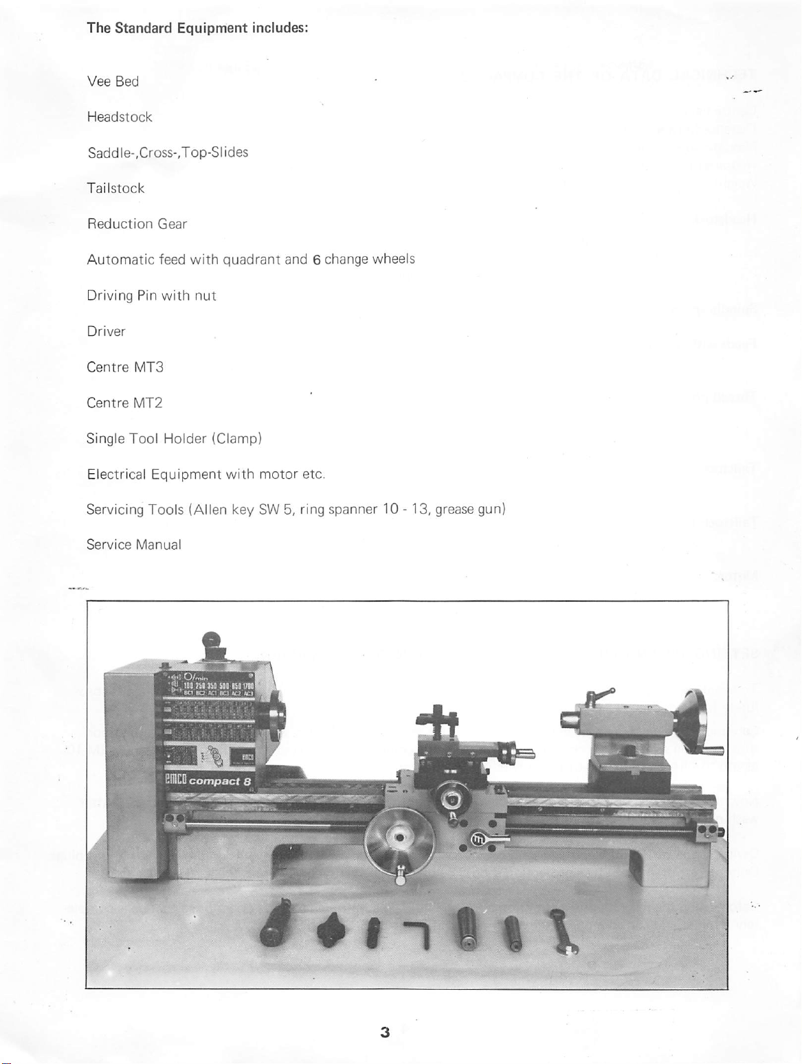
The
Standard
Vee
Bed
Headstock
Saddle-.Cross-,Top-Slides
Tai
lstock
Equipment
includes:
Reduction
Automatic
Driving
Driver
Centre
Centre
Single
Electrical
Servicing
Service
Gear
feed
Pin
with
MT3
MT2
Tool
Holder
Equipment
Tools
Manual
with
quadrant
nut
(Clamp)
with
(Allen
key
and 6 change
motor
SW
5,
ring
etc.
wheels
spanner
10-13,
grease
gun)
O
Page 5
TECHNICAL
DATA
OF
THE
COMPACTS
Centre
Distance
Max.
Required
height
between
jdia.
over
floor
Weight
Headstock:
spindle'nose
morse
hol
spindle
Spindle
Feeds
Thread
speeds:
with
leadscrew:
pitches:
Tailstock:
Tailstock
travel:
centres
slide
space
DIN
55021
taper
No.
3
low
spindle
(inside
bearings: 2 adjustable
100,
250,
350,
500,
105
mm
450
mm
118
mm
940 x 500
58
kg
dia.)
20
mm
mm
precision
850,
1700
revs/min.
0,09
mm/rev.
0,18
mm/rev.
metric
inch
module
spindle
spindle
morse
forward
backward 8 mm
0,4 - 3mm
10-44
thread/inch
0,2 - 0,7
diameter
travel
taper
12
mm
taper
roller
26mm
40mm
MT2
bearings
Motor:
SETTING
To
avoid
twisting
lutely
flat
and
Care
must
thus
avoiding
length
Now
washing,
Owing
Only
Before
tely
to
suit
the
protecting
clean
to
the
plugs
using
familiar
UP
AND
level.
also
be
swing
the
with
variety
with
built-in
the
machine
and
confident
PREPARING
of
the
bed,
taken
that
the
and
working
thickness
oil
dry,
of
of
film
(for
soft
cloth.
electric
fuse
protection
the
with
care
should
stand
single
speed
phase
1375
capacity
FOR
OPERATION
be
on
which
inaccuracies.
table)
firmly
storage
Finally
plugs,
onto
and
oil
EMCO
should
instruction
the
book
machine
a.
c.
rpm
0,5
PS
OF
taken
that
the
the
machine
The
machine
the
stand.
transport)
the
machines
be
should
and
should
slide
ways
are
used.
The
be
its
controls.
read
THE
MACHINE
location
should
with
supplied
to
is
mounted
be
be
removed
acid-free
with
which
is
fixed
bare
green/yellow
throughly
by
the
machine
securely
is
bolted
fastened
with 2 hex-headed
by
washing
with
paraffin.
oil.
ends
on
the
cables,without
wire
is
the
earth
connection!
its
operator
so
that
to
the
screws
he
is
is
abso
floor,
(M
10,
After
plugs.
comple
Page 6
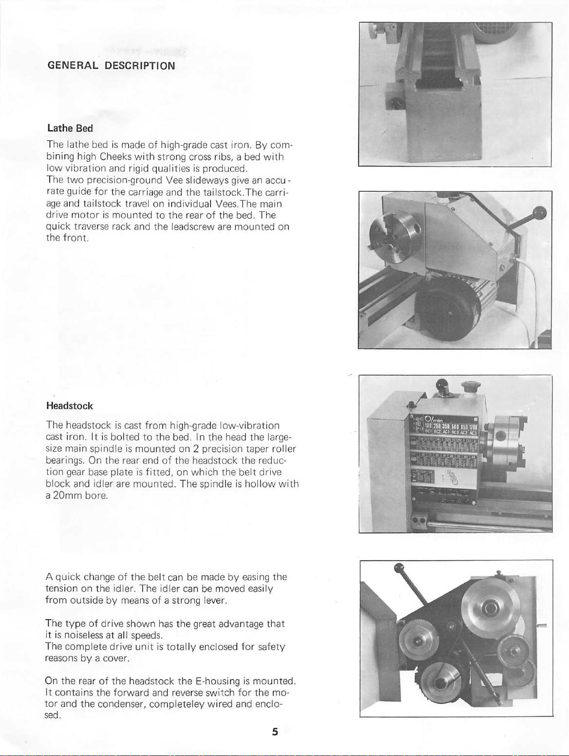
GENERAL
Lathe
Bed
The
lathe
bining
low
The
rate
age
drive
quick
the
high
vibration
two
guide
and
motor
traverse
front.
DESCRIPTION
bed
is
made
of
high-grade
Cheeks
precision-ground
for
tai
lstock
is
with
and
rigid
the
carriage
travel
mounted
rack
and
strong
qual
ities
Vee
and
on
individual
to
the
the
leadscrew
cast
iron.
cross
ribs,
a bed
is
produced.
slideways
the
rear
give
tai
lstock.The
Vees.The
of
the
bed.
are
mounted
By
an
main
The
com
with
accu
carri
on
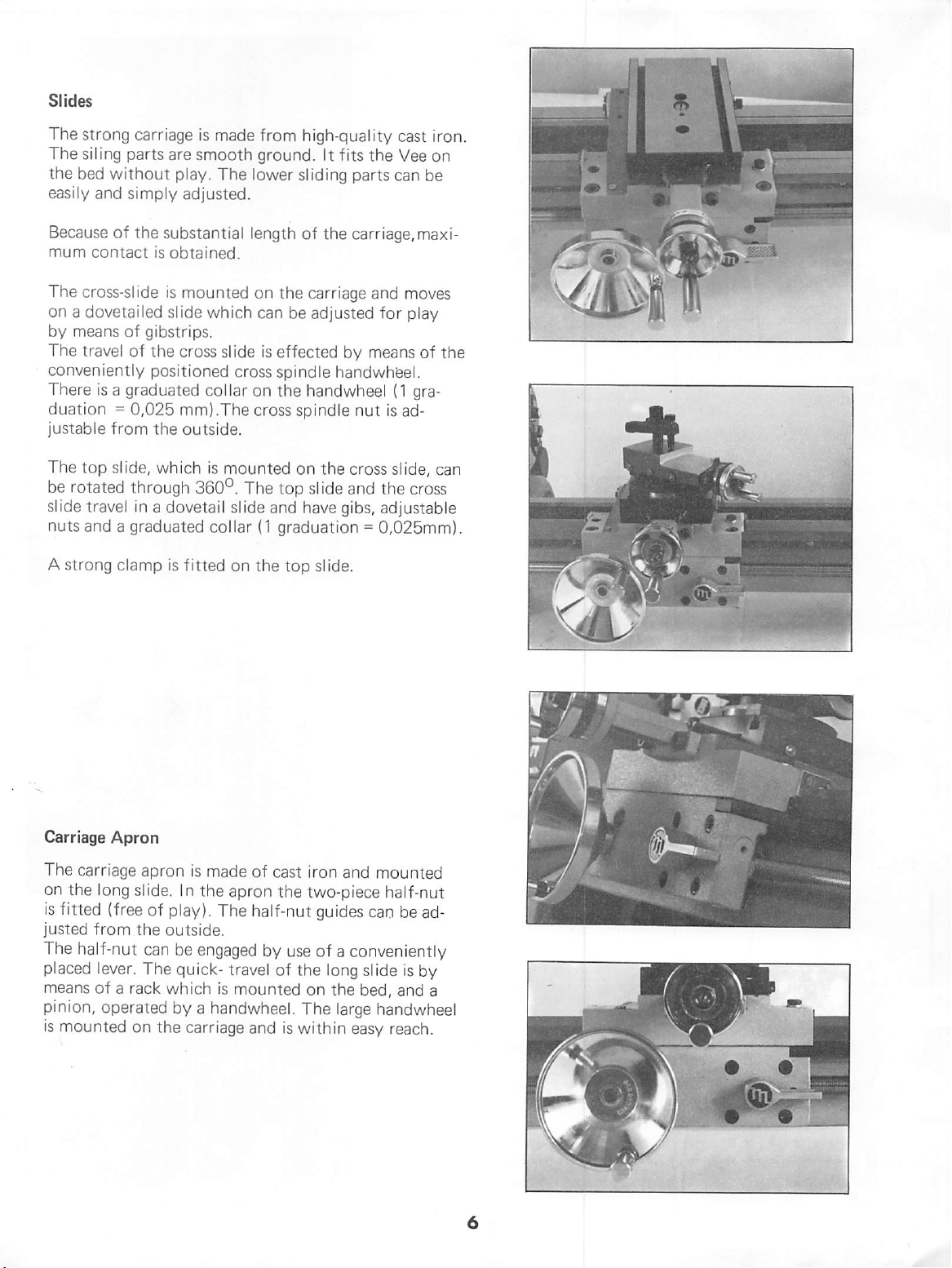
Headstock
The
headstock
cast
iron.
It
size
main
spindle
bearings.
tion
block
a
20mm
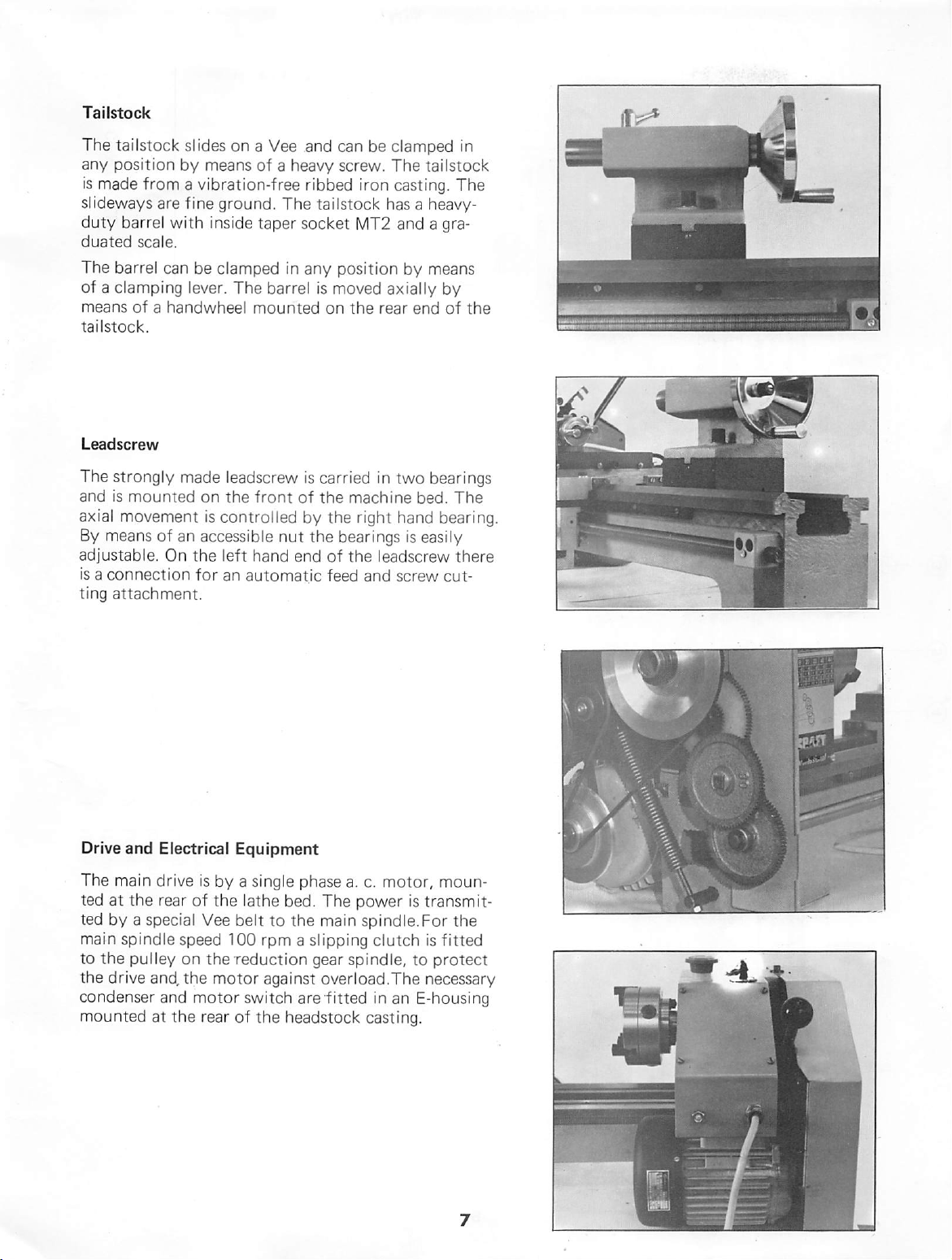
A
quick
tension
from
The
It
is
The
reasons
On
It
contains
tor
sed.
On
gear
base
and
bore.
change
on
outside
type
of
noiseless
complete
by a cover.
the
rear
and
the
is
cast
from
is
bolted
the
plate
idler
the
idler.
by
drive
at
drive
of
the
the
forward
to
is
mounted
rear
end
is
fitted,
are
mounted.
of
the
The
means
shown
all
speeds.
unit
headstock
condenser,
high-grade
the
bed.
In
the
on 2 precision
of
the
headstock
on
which
The
spindle
belt
can
be
made
idler
can
be
of a strong
has
is
total
and
reverse
completeley
lever.
the
great
ly
enclosed
the
E-housing
switch
wired
low-vibration
head
the
large-
taper
roller
the
reduc
the
belt
drive
is
hol
low
with
by
easing
moved
advantage
for
for
and
the
easily
that
safety
is
mounted.
the
mo
enclo
Page 7
Slides
The
strong
The
siling
the
bed
easily
and
carriage
parts
are
without
play.
simply
is
made
from
smooth
adjusted.
The
ground.
lower
high-quality
It
fits
sliding
cast
the
Vee
parts
can
iron.
on
be
Because
mum
The
on a dovetailed
by
The
conveniently
There
duation = 0,025
justable
The
be
slide
nuts
A
strong
of
the
substantial
contact
cross-slide
is
obtained.
is
mounted
slide
means
of
travel
of
gibstrips.
the
cross
positioned
is a graduated
mm).The
from
the
outside.
top
slide,
which
rotated
through
travel
in a dovetail slide
and a graduated
clamp
is
fitted
length
on
which
slide
cross
col
lar
on
cross spindle
is
mounted
360°.
The
collar
on
the
of
the
carriage,maxi
the
carriage
can
be
adjusted
is
effected
spindle
the
handwheel
on
top slide
and
have
(1
graduation = 0,025mm).
top
slide.
and
for
by
means
handwheel.
(1
nut
is
the
cross
slide,
and
the
gibs,
adjustable
moves
play
gra
ad
cross
of
can
the
M-
Carriage
The
on
is
fitted
justed
The
placed
means
pinion,
is
mounted
Apron
carriage
the
long
(free
from
half-nut
lever.
of a rack
operated
apron
slide,
the
The
In
of
play).
outside.
can
be
quick-
which
is
made
the
apron
The
engaged
travel
is
mounted
by a handwheel.
on
the
carriage
of
cast
iron
the
two-piece
half-nut
by
guides
use
of a conveniently
of
the
long
on
the
The
and
is
within
and
mounted
half-nut
can
slide
bed,
large
handwheel
easy
reach.
be
ad
is
by
and
a
Page 8
Tailstock
The
tailstock
any
position
is
made
slideways
duty
barrel
duated
The
scale.
barrel
of a clamping
means
tailstock,
Leadscrew
The
and
axial
By
adjustable.
is a connection
ting
of a handwheel
strongly
is
mounted
movement
means
attachment.
slides
by
from a vibration-free
are
fine
with
can
be
lever.
made
of
an
On
the
for
on a Vee
means
ground.
inside
clamped
The
mounted
leadscrew
on
the
front
is
control
accessible
left
hand
an
automatic
and
of a heavy
The
taper
socket
in
any
barrel
is
of
led
by
nut
end
can
be
screw.
ribbed
iron
tailstock
MT2
position
is
moved
on
the
rear
carried
the
the
the
of
feed
in
machine
right
bearings
the
leadscrew
and
clamped
The
casting.
tai
lstock
in
The
has a heavy-
and a gra
by
means
axial
ly
by
end
of
the
two
bearings
bed.
The
hand
bearing.
is
easily
there
screw
cut
Drive
and
Electrical
The
main
drive
ted
at
the
rear
ted
by a special
main
spindle
to
the
pul
ley
the
drive
and,
condenser
mounted
and
at
the
Equipment
is
by a single
of
the
Vee
belt
speed
on
the
the
100
reduction
motor
motor
rear
of
phase
a.
lathe
bed.
The
to
the
main
rpm a slipping
gear
spindle,
against
switch
the
overload.The
are
fitted
headstock
c.
motor,
power
spindle.For
clutch
moun
is
transmit
the
is
fitted
to
protect
necessary
in
an
E-housing
casting.
Page 9
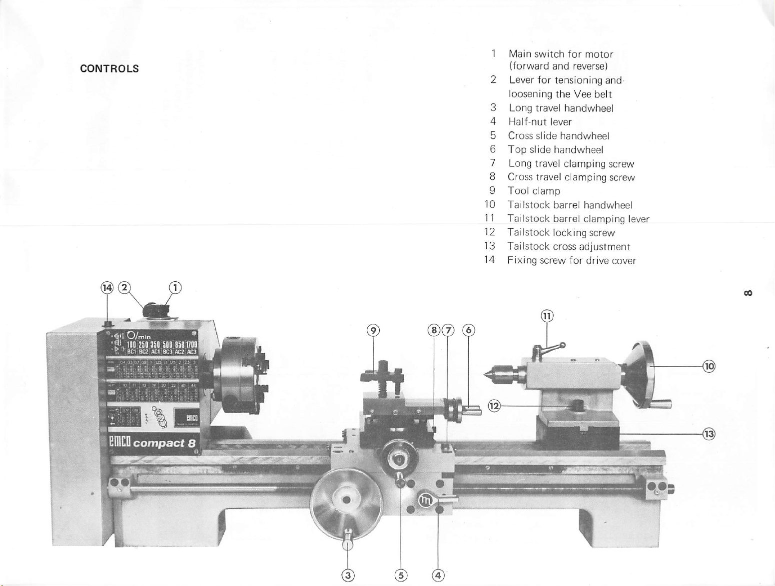
CONTROLS
1
Main
{forward
2
Lever
loosening
3
Long
4
Half-nut
5
Cross
6
Top
7
Long
8
Cross
9
Tool
10
Tai
11
Tai
12
Tailstock
13
Tai
14
Fixing
switch
and
for
tensioning
the
travel
lever
slide
slide
handwheel
travel
travel
clamp
lstock
lstock
barrel
barrel
locking
lstock
cross
screw
for
motor
reverse)
Vee
belt
handwheel
handwheel
clamping
clamping
handwheel
clamping
screw
adjustment
for
drive
and'
screw
screw
lever
cover
a'iO/min
! 100
250
350
500
V
BC1
BQ
ciUCu
compact
ACl
05017081
BC3
ACZ
*
ACS'
CBICDK
B
T-
•
-tv
•li
•:
Page 10
WORKING
WITH
THE
COIVIPACT
8
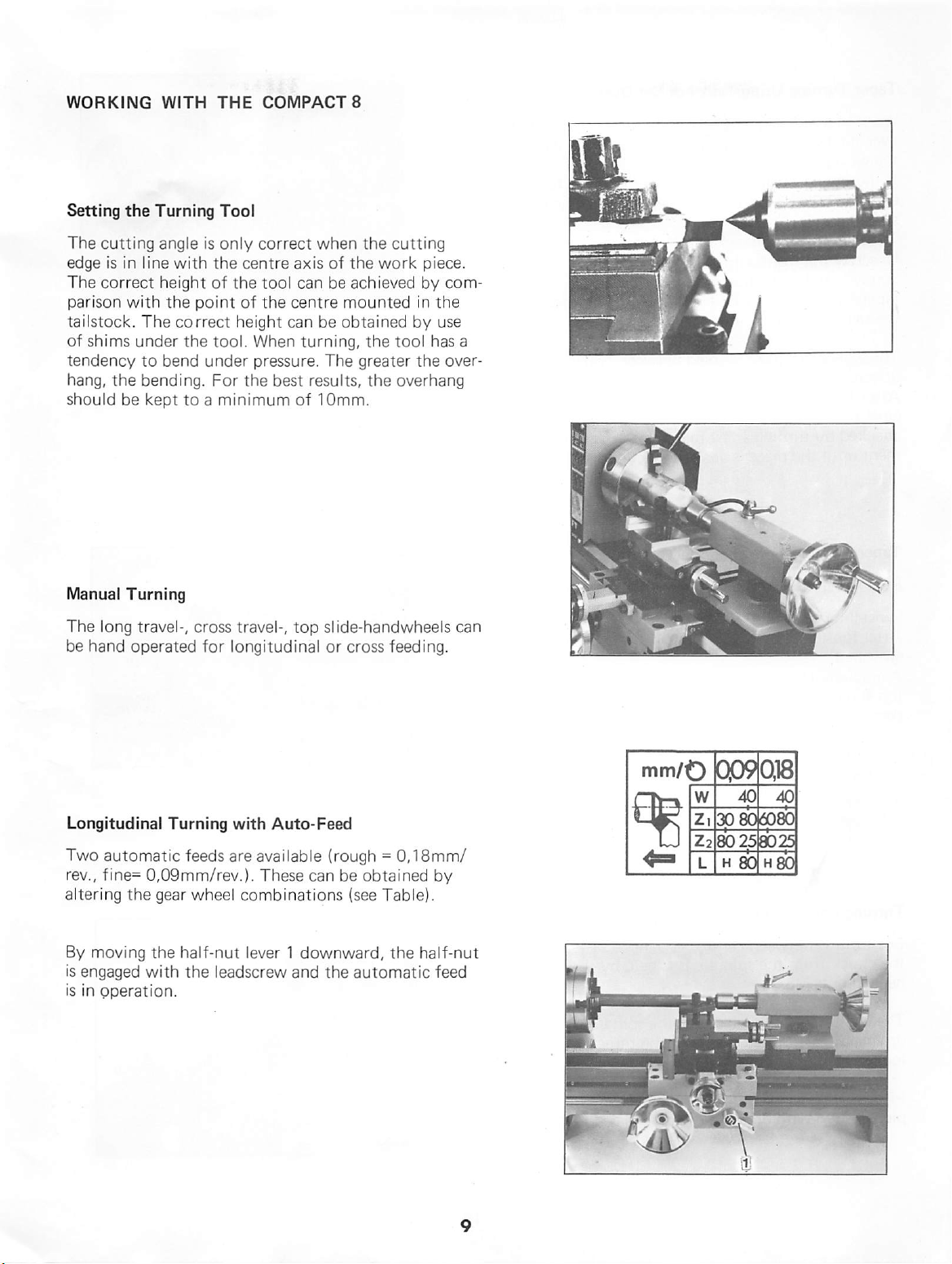
Setting
The
edge
The
parison
tai
of
tendency
hang,
should
Manual
The
be
the
cutting
is
in
line
correct
with
lstock.
shims
hand
The
under
to
the
bending.
be
Turning
long
travel-,
operated
Turning
angle
is
with
height
the
point
correct
the
bend
kept
to a minimum
cross
for
Tool
only
correct
the
centre
of
the
tool
of
the
centre
height
tool.
under
For
travel-,
longitudinal
can
When
pressure.
the
best
top slide-handwheels
when
the
axis
of
the
can
be
achieved
mounted
be
obtained
turning,
The
greater
results,
of
10mm.
or
cross
cutting
work
the
tool
the
overhang
feeding.
piece.
by
com
in
the
by
use
has
the
over
a
can
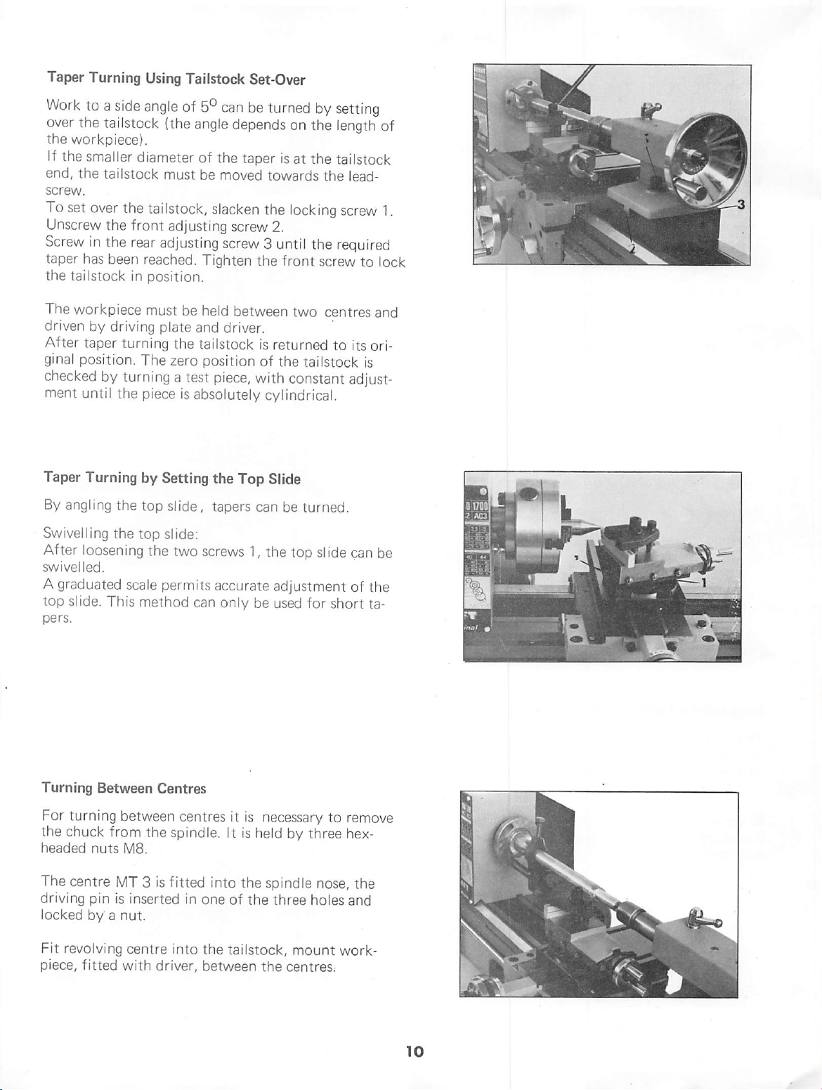
Longitudinal
Two
automatic
rev.,
fine=
altering
By
moving
is
engaged
is
in
operation.
Turning
0,09mm/rev.).
the
gear
the
half-nut
with
with
feeds
are
wheel
the
leadscrew
Auto-Feed
avai
lable
(rough = 0,18mm/
These
can
be
obtained
combinations
lever 1 downward,
and
(see
the
automatic
Table).
the
half-nut
by
feed
mm/O
-|W
0090,18
Iw"
40 40
zi
opaotfo
Z2
80
25
L H 80
80
H
Page 11
Taper
over
the
end,
screw.
To
Screw
taper
the
The
driven
After
ginal
checked
ment
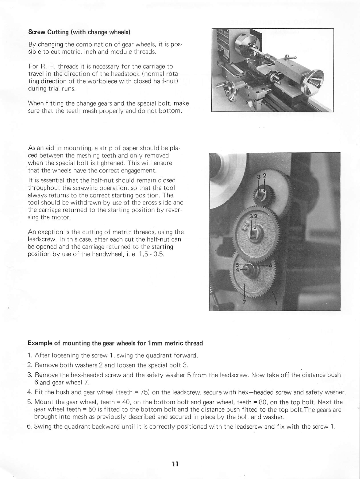
Taper
Turning
Work
to a side
the
tailstock
workpiece}.
If
the
smaller
the
tailstock
set
over
Unscrew
the
In
the
has
been
tai
lstock
workpiece
by
taper
position.
by
until
Turning
driving
the
Using
Tailstock
angle
of
5°
can
(the
angle
diameter
the
tailstock,
front
rear
reached.
in
position.
must
turning
The
turning a test
piece
by
of
the
must
be
moved
slacken
adjusting
adjusting
plate
the
zero
screw 3 until
Tighten
be
held
and
driver.
tai
lstock
position
piece,
is
absolutely
Setting
the
Set-Over
be
turned
depends
taper
screw
between
Top
on
Is
at
towards
the
locking
2.
the
front
two
is
returned
of
the
with
constant
cylindrical.
Slide
by
setting
the
length
the
tai
the
screw
the
required
screw
centres
to
tai
lstock
of
lstock
lead-
1.
to
lock
and
its
ori
is
adjust
By
angling
Swivel
swivel
top slide.
Turning
For
the
headed
The
driving
locked
ling
After
loosening
led.
A
graduated
This
pers.
Between
turning
chuck
from
nuts
centre
pin
by a nut.
the
top
slide,
the
top
slide:
the
scale
permits
method
Centres
between
the
M8.
MT 3 is
is
inserted
tapers
two
screws
accurate
can
only
centres
spindle.
fitted
in
It
into
one
it
of
can
be
turned.
1,
the
top
adjustment
be
used
is
necessary
is
held
by
the
spindle
the
three
slide
can
of
for
short
to
remove
three
hex-
nose,
holes
and
be
the
ta
the
Fit
revolving
piece,
fitted
centre
with
driver,
into
the
between
tai
lstock,
the
mount
centres;
work-
Page 12
Screw
sible
For
travel
ting
during
When
sure
As
ced
when
that
It
throughout
always
tool
the
sing
Cutting
By
changing
to
cut
R.
H.
in
direction
trial
fitting
that
an
aid
between
the
the
is
essential
returns
should
carriage
the
metric,
threads
the
runs.
the
in
special
wheels
the
be
motor.
(with
change
the
combination
inch
it
is
direction
of
the
workpiece
the
change
teeth
mesh
mounting, a strip
the
meshing
bolt
is
have
the
that
the
screwing
to
the
correct
withdrawn
returned
to
wheels)
of
and
module
necessary
of
the
headstock
gears
and
properly
teeth
tightened.
correct
half-nut
operation,
starting
by
use
the
starting
gear
wheels,
threads.
for
the
carriage
(normal
with
closed
the
special
and
do
of
paper
should
and
only
This
will ensure
engagement.
should
remain
so
that
position.
of
the
cross
position
it
is
half-nut)
bolt,
not
bottom.
be
removed
closed
the
tool
The
slide
by
rever
pos
to
rota
make
pla
and
An
exeption
leadscrew.
be
opened
position
Example
1.
After
2.
Remove
3.
Remove
6
and
4.
Fit
5.
Mount
gear
brought
6.
Swing
In
and
by
of
loosening
the
gear
the
bush
the
wheel
into
the
is
the
cutting
this
case,
the
carriage
use
of
the
mounting
the
both
washers 2 and
hex-headed
wheel
7.
and
gear
gear
wheel,
teeth = 50
mesh
quadrant
of
metric
after
each
returned
handwheel,
the
gear
wheels
screw
1,
swing
loosen
screw
wheel
(teeth = 75)
teeth - 40,
is
fitted
as
previously
backward
threads,
cut
the
half-nut
to
the
i.
e.
1,5 - 0,5,
for
1mm
the
quadrant
the
special
and
the
safety
on
the
to
the
bottom
described
until
it
is
correctly
using
the
can
starting
metric
forward.
bolt
washer 5 from
on
the
leadscrew,
bottom
bolt
and
secured
thread
3.
the
secure
bolt
and
gear
and
the
distance
in
place
positioned
with
:^ii
leadscrew.
with
hex—headed
wheel,
by
teeth = 80,
bush
fitted
the
bolt
the
leadscrew
Now
to
and
take
off
screw
on
the
the
top
washer.
and
fix
with
the
distance
and
safety
top
bolt.
Next
bolt.The
the
gears
screw
bush
washer.
the
are
1.
Page 13
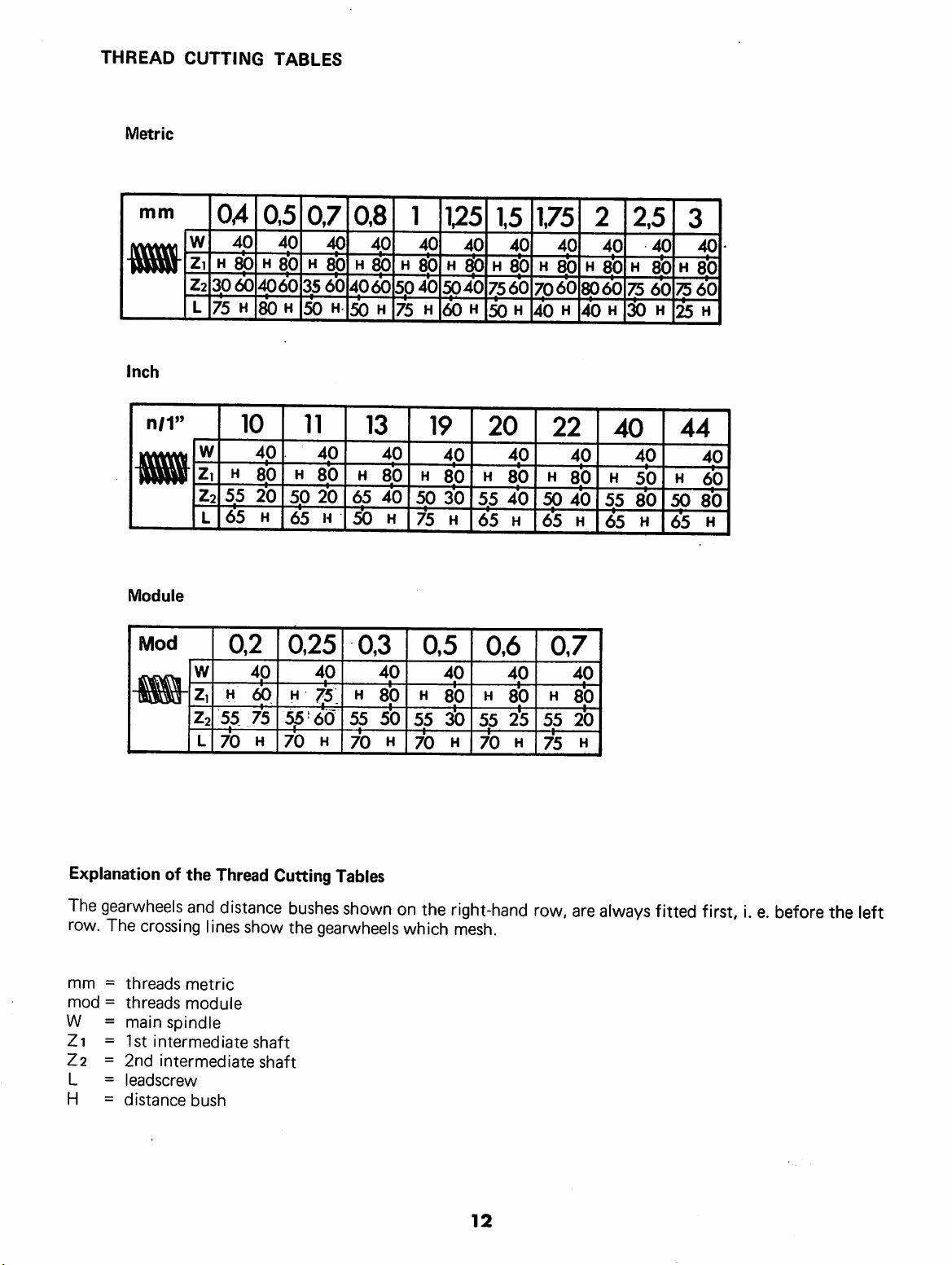
THREAD
Metric
CUTTING
TABLES
mm
m
Inch
n/1"
Mil
Module
Mod
laSSjiLr
OA
w
40
ZiH 80
Z2
3060
L
75
w
Zi
H 80
55
Z2
L
65
0,2
w
H 60
Z,
55
Z2
L
70
H
10
4p
0,5
H
4060
80
40
20
H
75
H
07
40
80
35
H
50
11
H
50
65
0,25
H
55'60
70
0,8
40
40
H
80
H
80
60
4060
H
50
13
40
80
H
20
65
H
50
0,3
40 40
75
H
55
H
70
5p40
H
75
40
80
40
H
80
50
H
1
H
40
8b
H
19
50
75
z
Z
0,5
55
70
175
40
H fib
5040
60
40
.o.
,o
30
OC
00
H
40
:ib
H
H
50
20
H
55
65
0,6
H
55
70
15
40
H
8b
7560
40
80
40
40
80
2*5
H
H
H
1,75
40
H
80
7060
40
H
22
40
H
80
50
40
65
0,7
H
55
75
8060
40
H
40
80
20
H
H
2
40
80
H
H
55
65
40
2,5
H
75
30
40
50
80
H
40
8*0
60
H
3
H
75
25
44
H 60
50
65
40
80
60
H
40
80
H
Explanation
The
gearwheels
row.
The
mm = threads
mod = threads
W =
Zi
=
7.2 = 2nd
L =
H =
of
the
and
crossing lines
metric
module
main
spindle
1st
intermediate
intermediate
leadscrew
distance
Thread
distance
show
shaft
shaft
bush
Cutting
Tables
bushes
the
shown
gearwheels
on
the
which
right-hand
row,
are
mesh.
12
always
fitted
first,
i.
e.
before
the
left
Page 14
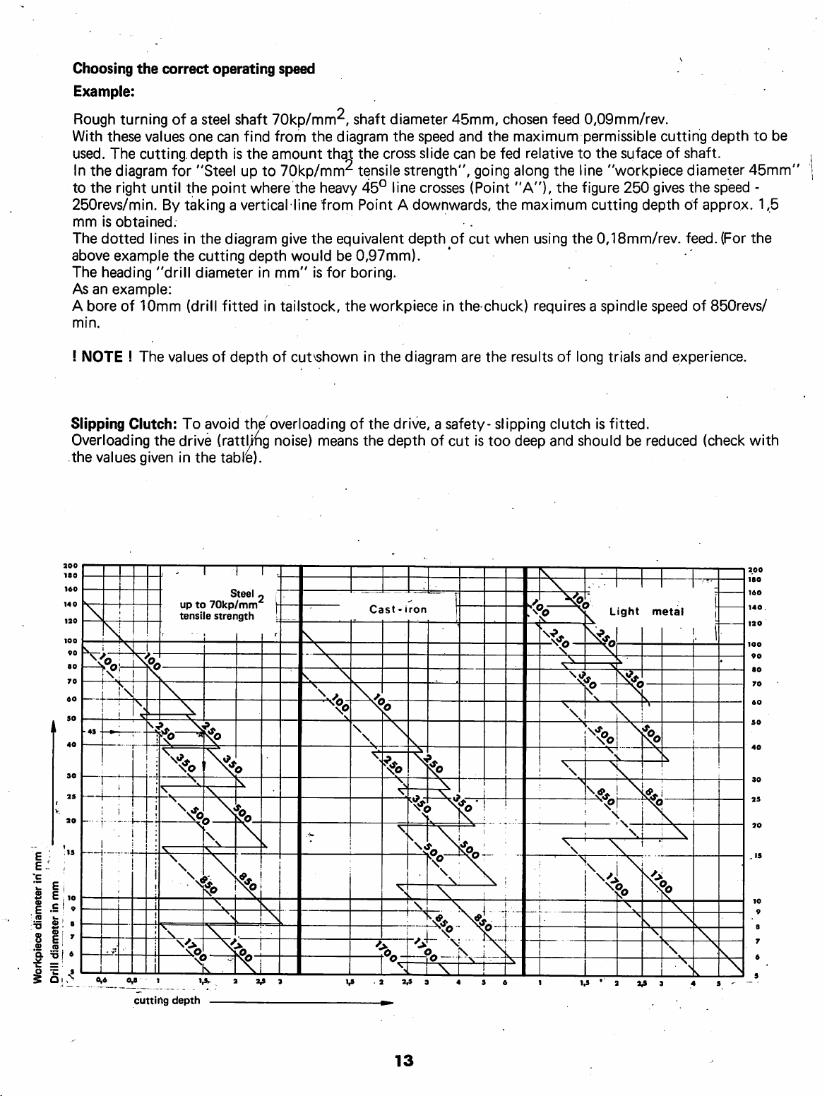
Choosing
Example:
the
correct
operating
speed
Rough
With
used.
In
to
250revs/min.
mm
The
above
The
As
A
min.
!
Slipping
Overloading
the
turning
these
values
The
cutting.depth
the
diagram
the
right
until
is
obtained.
dotted
lines
example
heading
an
example:
bore
NOTE I The
"drill
of
10mm
Clutch:
the
values
given
of a steel
one
for
the
By
taking a vertical
in
the
(drill
values
To
drive
in
shaft
can
find
is
the
"Steel
cutting
diameter
point
the
diagram
fitted
of
depth
avoid
up
to
where
depth
in
in
the
(ratth^g
the
table).
70kp/mm^,
from
the
amount
70kp/mm^
the
line
give
the
would
mm"
tailstock,
of
cut^shown
overloading
noise)
shaft
diagram
that
the
tensile
heavy
45°
from
Point A downwards,
equivalent
be
0,97mm).
is
for
boring.
the
workpiece
in
of
the
means
the
diameter
the
cross
strength",
line
the
diagram
drive, a safety-
depth
45mm,
speed
and
slide
can
crosses
depth
of
in
the
are
of
cut
going
(Point
cut
is
chosen
the
maximum
be
fed
relative
along
"A"),
the
maximum
when
using
chuck)
the
too
requires a spindle
results
slipping
deep
feed
0,09mm/rev.
permissible
to
the
suface
the
line
"workpiece
the
figure
250
cutting
the
0,18mm/rev.
of
long
trials
clutch
and
is
fitted.
should
be
cutting
of
depth
shaft.
diameter
gives
the
speed
depth
of
approx.
feed.
(For
speed
of
850revs/
and
experience.
reduced
(check
to
be
45mm"
-
1,5
the
with
0,6
0,6
cutting
I
up
to
tensile
1,6,. a V
depth
70kp/mm
strength
Cast - iron
3
1,6
.2
3,6
3
Light
1,6 ' 3
3,6
metal
3
4
6
13
Page 15
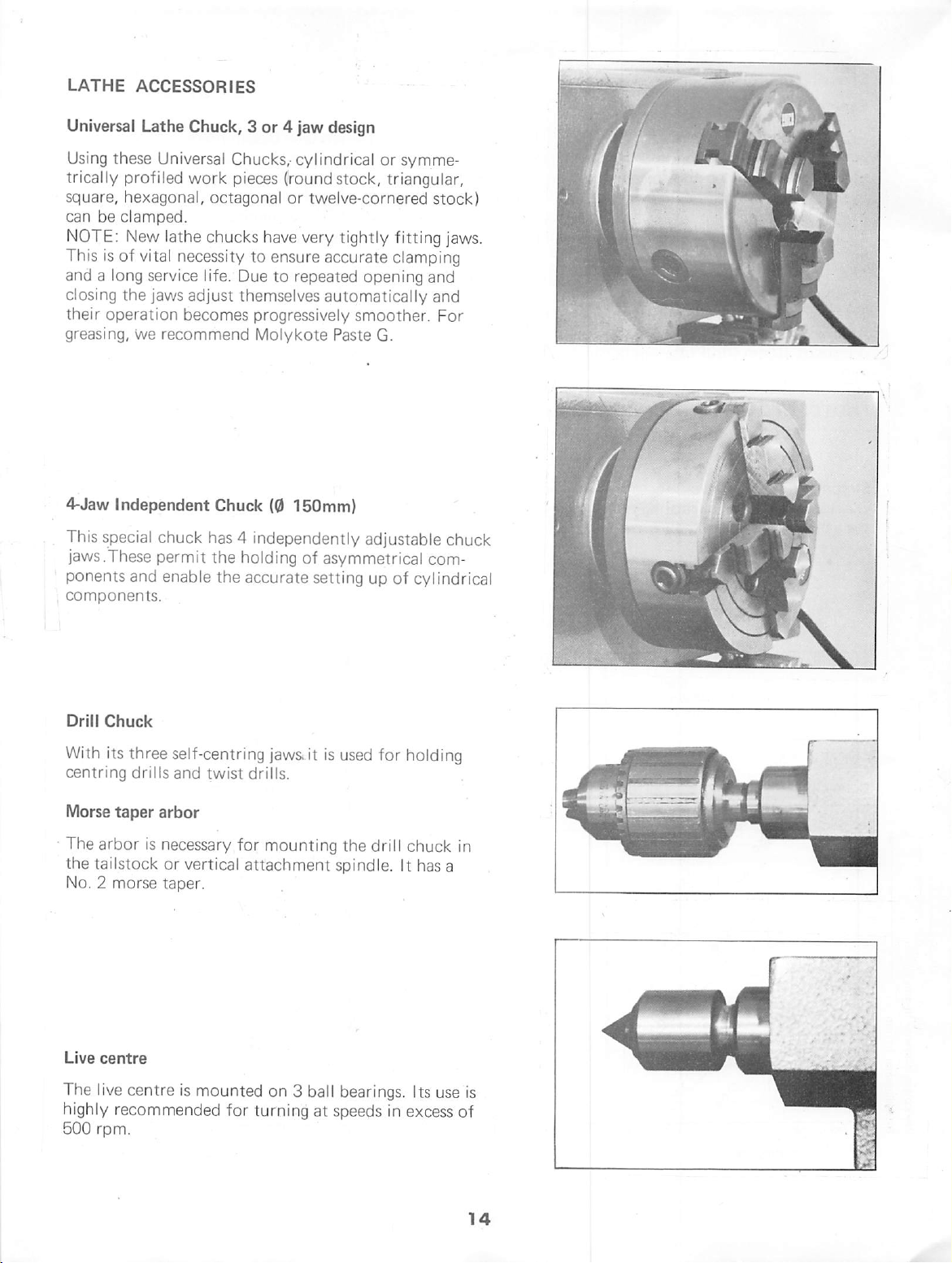
LATHE
ACCESSORIES
Universal
Using
trical
square,
can
NOTE:
This
and a long
closing
their
greasing,
4-Jaw
This
jaws.'These
ponents
components.
Lathe
Chuck, 3 or 4 jaw
these
Universal
ly
profiled
hexagonal,
be
clamped.
New
is
of
vital
work
lathe
necessity
service
the
jaws
adjust
operation
Independent
special
becomes
we
recommend
chuck
permit
and
enable
design
Chucks,'
pieces
octagonal
chucks
life.
Due
themselves
Chuck
has 4 independently
the
holding
the
accurate
cylindrical
(round
have
to
ensure
to
progressively
Molykote
(0
stock,
or
twelve-cornered
very
tightly
accurate
repeated
150mm)
opening
automatically
smoother.
Paste
G.
adjustable
of
asymmetrical
setting
up
or
symme
triangular,
stock)
fitting
jaws.
clamping
and
and
For
chuck
com
of
cylindrical
Drill
Chuck
With
its
three
centring
Morse
The
the
No. 2 morse
Live
The
highly
500
drills
taper
arbor
is
tai
lstock
centre
live
centre
recommended
rpm.
self-centring
and
twist
arbor
necessary
or
vertical
taper.
is
mounted
jaws
drills.
for
mounting
attachment
on 3 ball bearings.
for
turning
it
is
used
the
spindle.
at
speeds
for
holding
drill
chuck
It
has
Its
in
excess
in
a
use
is
of
Page 16

Fixed
steady
The
fixed
steady
shafts
on
the
the
tailstock
tool
or
the
moved
which
running
on
position
require
with
from
functions
of
the
bedway
by
continuous
the
workpiece
serves
free
tailstock
cannot
drilling
the
the
means
be
tool,
machine.
as
end
machine.
and
secured
of a locking
lubrication
to
predominantly
end.
For
many
used
as
it
obstructs
and
therefore
It
is
then
the
support
The
prevent
ensuring a chatter-free
fixed
steady
from
below
plate.
The sliding
at
the
contact
their
premature
as a support
operations
the
must
be
fixed
is
mounted
in
the
for
turning
re
steady
desired
fingers
points
wear.
Travelling
The
thus
centre
the
height
quired,
tool.
tions
ging"
ning
The
xed
be
adequately
Setting
1.
Slacken
2.
Unscrew
ding
steady
travelling
follows
part
of
as
the
The
travel
on
long,
of
the
tool.
sliding
fingers
steady,
the
steady
the
fingers 2 by
ficiently
with
its
fingers
fixed
steady
3.
By
turning
sliding
must
tight.
sl
4.
Whemafter
wear,
fingers
be
Tighten
iding
the
applied
points
steady
the
of
the
the
place
slender
is
movement
travelling
tool,
of
ling
steady
workpiece
are
free
of
play,
lubricated
three
laterally
the
knurled
hand.
wide
until the
around
in
its
position.
the
knurled
can
be
free
the
hexagonal
with
machine
prolonged
tips
of
the
mounted
only
the
third
workpieces.
under
set
similarly
but
during
screws 3 and
Open
fixed
the
screws
set
of
play
operating
fingers
on
of
the
turning
steady
two sliding
is
is
taken
used
for
the
pressure
is
It
to
not
binding.
the
located
the
sliding
steady
workpiece.
into
to
the
workpiece.
but
must
nuts.
oil.
time
can
be
the
saddle
always
fingers
by
turning
prevents
those
and
tool.
level
are
the
opera
"sprin
of
the
of
the
They
operation.
hexagonal
advance
can
position,
Lubricate
remilled
fingers
be
Secure
They
not
be
the
jaws
the sli
moved
or
As
the
with
re
turning
tur
fi
should
nuts
1,
suf
the
the
too
the
show
filed.
Page 17
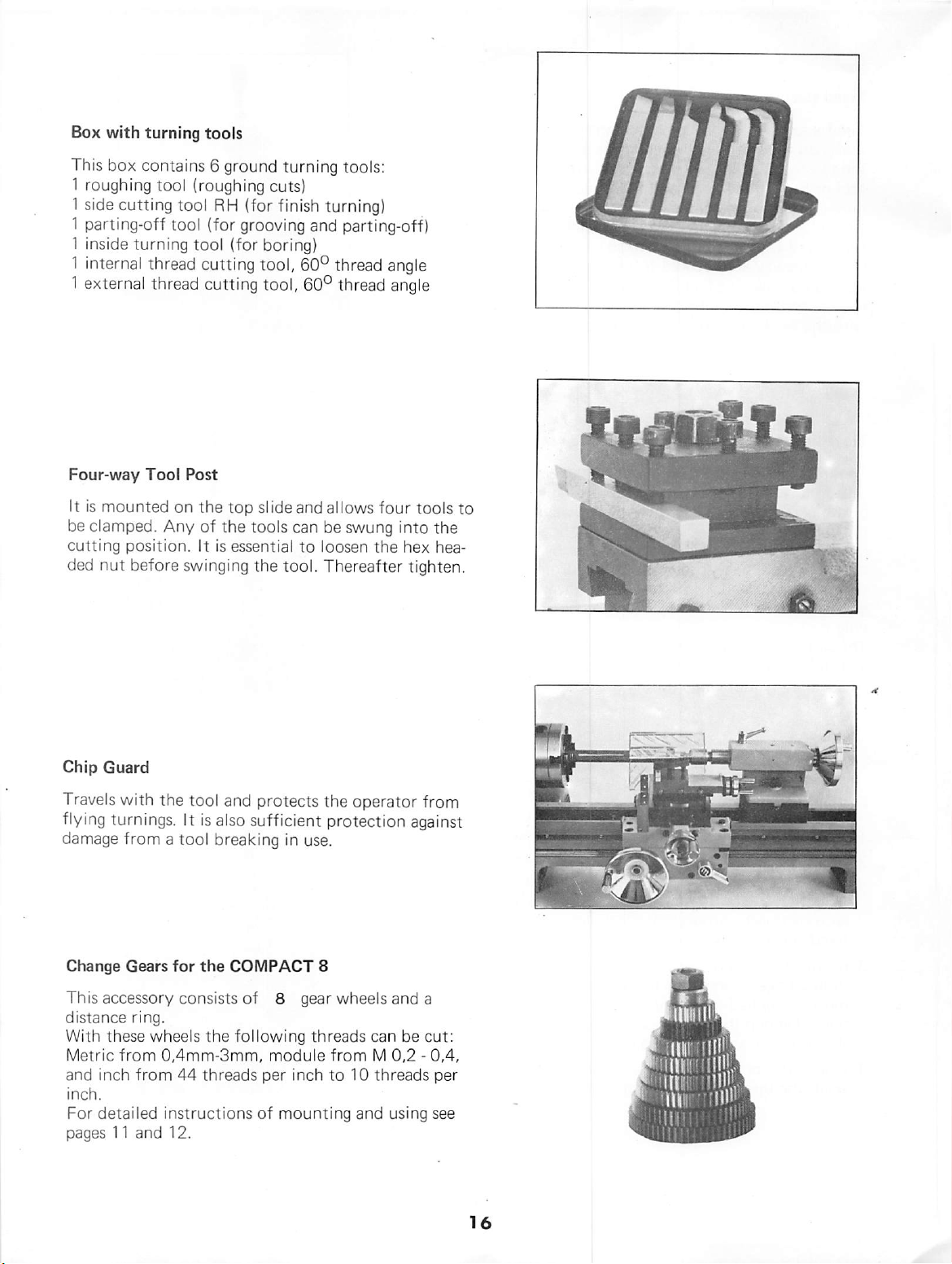
Box
with
turning
This
box
contains 6 ground
1
roughing
1
side
1
parting-off
1 inside
1 internal
1
external
tool
cutting
tool
tool
turning
thread
thread
tools
turning
(roughing
RH
(for
tool
cutting
cutting
cuts)
(for
finish
grooving
(for
boring)
tool,
tool,
tools;
turning)
and
parting-off)
60°
thread
60°
thread
angle
angle
Four-way
It
is
mounted
be
clamped.
cutting
ded
Chip
Travels
flying
damage
position.
nut
before
Guard
with
turnings.
from a tool
Tool
Post
on
Any
swinging
the
tool
It
the
top
slide
of
the
tools
It
is
essential
the
and
protects
is
also
sufficient
breaking
and allows
can
be
swung
to
loosen
tool.
Thereafter
the
operator
protection
in
use.
four
into
the
hex
tighten.
against
tools
to
the
hea
from
Change
This
distance
With
Metric
and
inch.
For
pages
Gears
for
the
accessory
these
from
inch
detailed instructions
11
consists
ring.
wheels
0,4mm-3mm,
from
44
and
12.
the
threads
COMPACT
of 8 gear
following
module
per
inch
of
mounting
8
wheels
threads
from M 0,2 - 0,4,
to
can
10
threads
and
and
be
using
a
cut:
per
see
Page 18
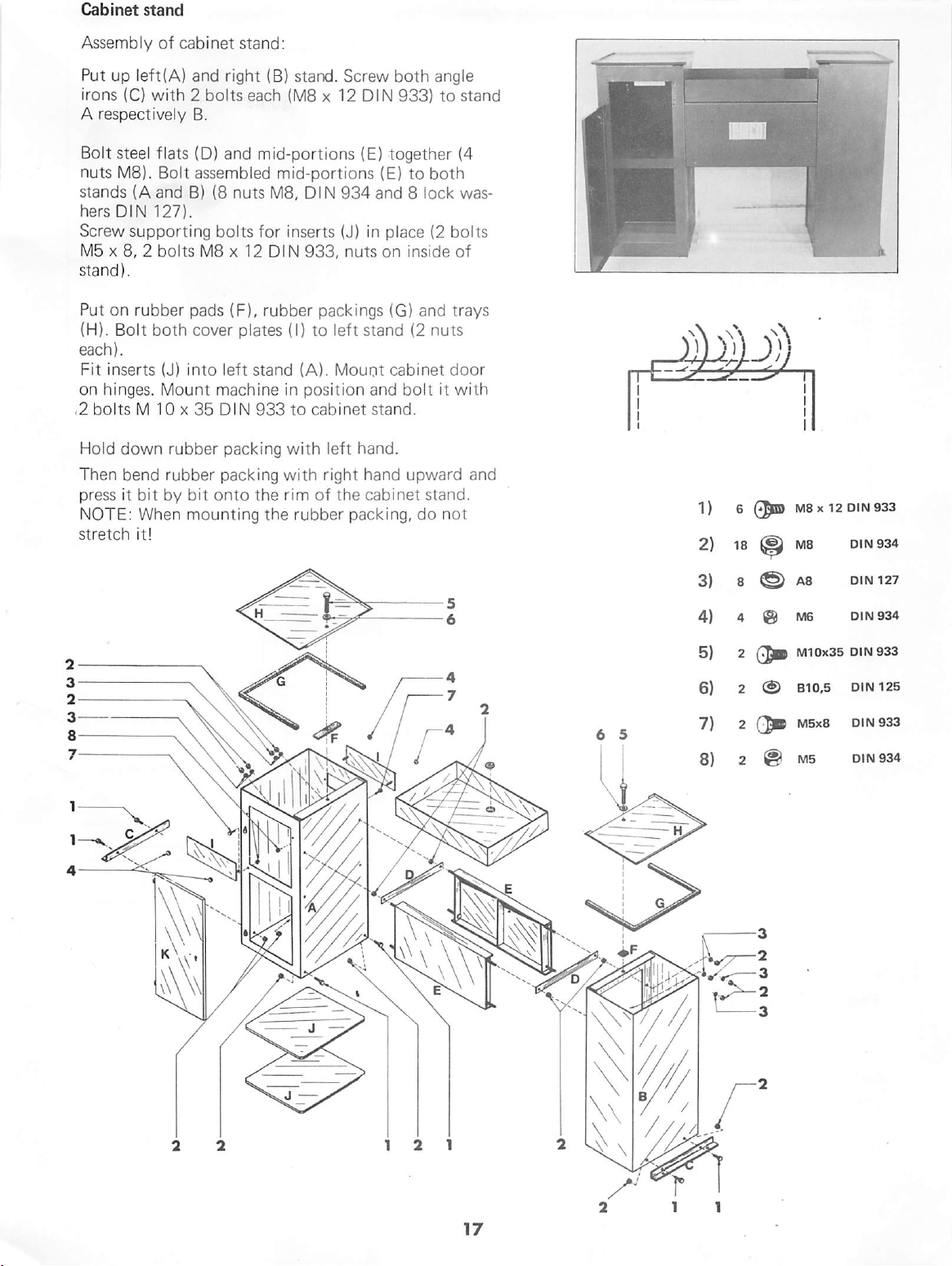
Cabinet
stand
Assembly
Put
irons
A
respectively
Bolt
nuts
stands
hers
Screw
M5 X 8, 2 bolts
stand).
Put
on
(H).
each).
Fit
inserts
on
hinges.
.2
bolts M 10 X 35
Hold
Then
press
NOTE:
stretch
of
cabinet
up
left(A)
(C)
with 2 bolts
steel
flats
M8).
Bolt
(A
and
DIN
127).
supporting
rubber
Bolt
both
(J)
Mount
down
rubber
bend
rubber
it
bit
by
When
it!
stand:
and
right
(B)
each
B.
(D)
and
mid-portions
assembled
B)
(8
nuts
bolts
for
M8 x 12
pads
(F),
rubber
cover
plates
into
left
stand
machine
Dl N 933
packing
packing
bit
onto
the
mounting
the
stand.
(MS x 12
Screw
DIN
(E)
mid-portions
M8,
DIN
inserts
DIN
933,
(E)
934
and 8 lock
(J)
in
nuts
packings
(I)
to
left
stand
(A).
Mount
in
position
to
cabinet
with
with
rim
of
rubber
left
hand.
right
hand
the
cabinet
packing,
and
stand.
both
angle
933)
to
stand
together
place
on
(G)
cabinet
bolt
(4
to
both
(2
bolts
inside
of
and
trays
(2
nuts
door
it
with
upward
stand.
do
not
was
and
)MjD
1) 6 0pn
2)
18 ^ M8
M8x12
0iN933
DIN
934
i
i
I
3) 8 ®
4)
4
@
5)
2
6)
2
7) 2 O
8) 2 @
A8
M6
M10x35
B10.5
M5x8
MB
DIN
127
DIN
934
DIN
933
DIN
125
DIN
933
DIN
934
Page 19
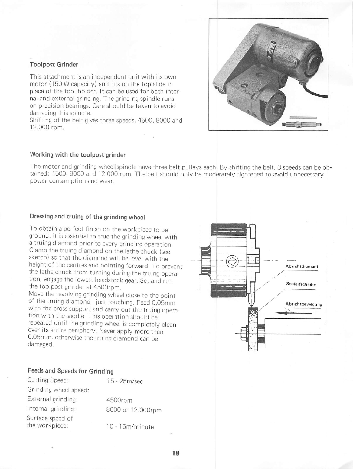
Toolpost
This
motor
place
nal
on
precision
damaging
Shifting
12.000
Grinder
attachment
{150 W capacity)
of
the
and
external
this
of
rpm.
is
an
tool
holder.
grinding.
bearings.
spindle.
the
belt
gives
independent
and
fits
It
can
The
Care
should
three
unit
on
be
used
grinding
be
speeds,
with
the
top
for
spindle
taken
4500,
its
own
slide
both
inter
runs
to
avoid
8000
in
and
Working
The
tained:
power
Dressing
To
ground,
a
truing
Clamp
sketch)
height
the
tion,
the
Move
of
the
with
tion
repeated
over
0,05mm,
damaged.
with
the
motor
and
4500,
8000
consumption
and
truing
obtain a perfect
it
is
essential
diamond
the
truing
so
that
of
the
centres
lathe
chuck
engage
toolpost
the
the
with
its
the
grinder
revolving
truing
diamond - just
cross
support
the
saddle.
until
the
entire
periphery.
otherwise
toolpost
grinding
and
and
of
the
wheel
12.000
wear.
finish
to
true
prior
to
diamond
the
diamond
and
pointing
from
turning
lowest
headstock
at
4500rpm.
grinding
and
This
grinding
Never
the
truing
grinder
.spindle
rpm.
grinding
on
the
the
every
grinding
on
the
will be
have
The
wheel
workpiece
grinding
lathe
level
forward.
during
the
gear.
wheel
close
touching.
carry
operation
wheel
apply
diamond
Feed
out
the
should
is
completely
more
three
belt
belt
should
to
be
wheel
with
operation.
chuck
(see
with
the
To
prevent
truing
Set
to
opera
and
run
the
point
0,05mm
truing
opera
be
clean
than
can
be
pulleys
only
each.
be
moderately
By
shifting
tightened
the
belt, 3 speeds
to
avoid
/"
can
be
unnecessary
Abrichtdismant
Schletfscheibe
Abrichtbewegung
ob
Feeds
and
Cutting
Grinding
External
Internal
Surface
the
Speed:
wheel
grinding:
grinding:
speed
workpiece:
Speeds
for
speed:
of
Grinding
15 - 25m/sec
4500rpm
8000
10 - 15m/minute
or
12.000rpm
Page 20
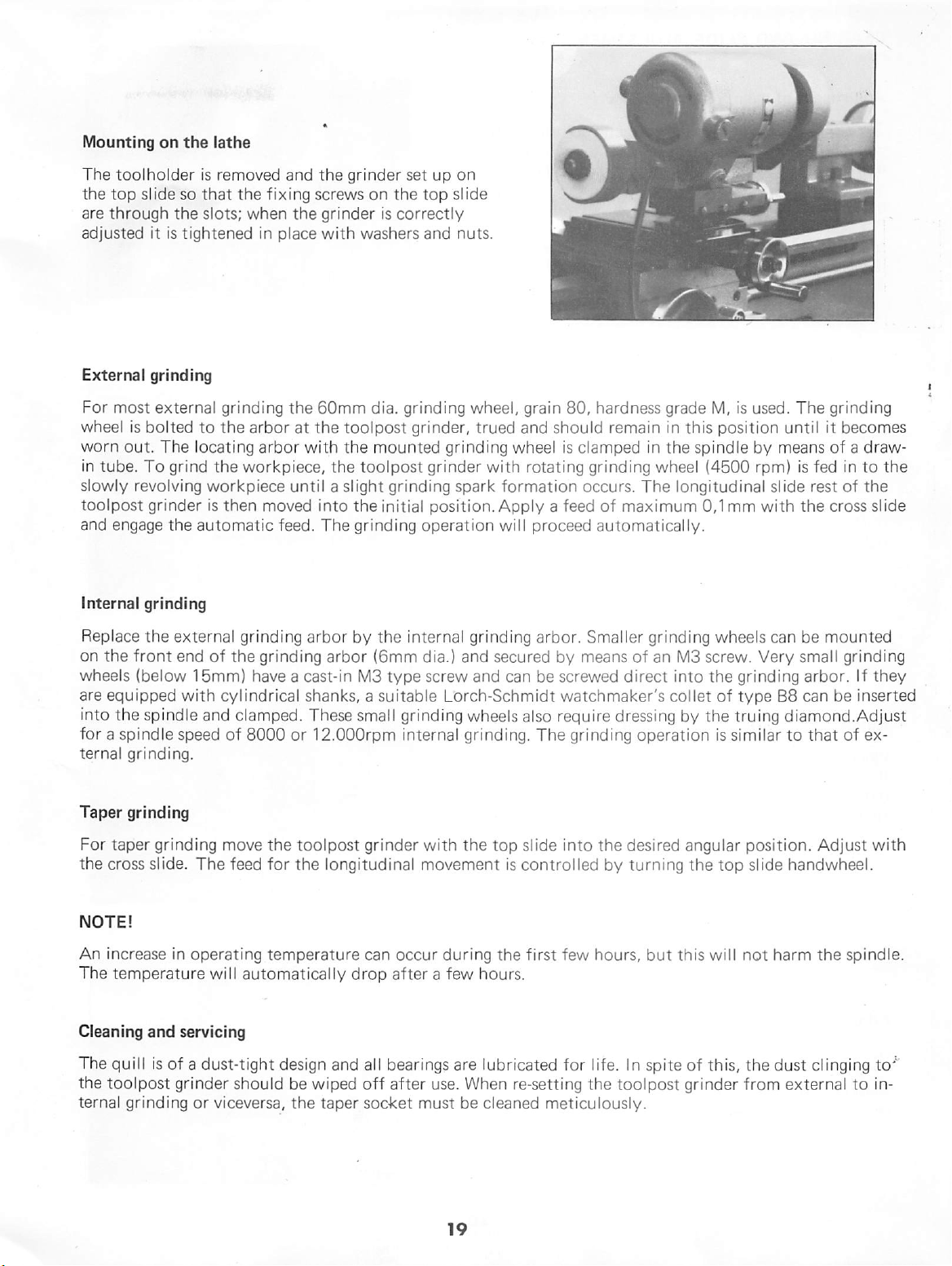
Mounting
The
toolholder
the
top
slide
are
through
adjusted
it
on
the
iathe
is
removed
so
that
the
slots;
is
tightened
the
when
in
and
the
fixing
screws
the
grinder
place
with
grinder
set
on
the
is
correctly
washers
up
on
top slide
and
nuts.
External
For
wheel
worn
in
tube.
slowly
toolpost
and
Internal
Replace
on
wheels
are
into
for a spindle
ternal
Taper
For
the
grinding
most
external
is
bolted
out.
The
To
grind
revolving
grinder
engage
the
grinding
the
the
front
(below
equipped
the
spindle
grinding.
grinding
taper
grinding
cross
slide.
external
end
15mm)
with
speed
grinding
to
the
arbor
locating
arbor
the
workpiece,
workpiece
is
then
moved
automatic
feed.
grinding
of
the
grinding
have a cast-in
cylindrical
and
clamped.
of
8000
move
the
The
feed
for
the
60mm
at
the
with
until a slight
into
The
arbor
shanks, a suitable
These
or
12.000rpm
toolpost
the
dia.
grinding
toolpost
the
the
toolpost
grinder,
mounted
grinding
the
initial
grinding
by
the
internal
arbor
(6mm
M3
type
small grinding
internal
grinder
longitudinal
wheel,
grinding
grinder
spark
position.
grain
trued
and
wheel
with
rotating
formation
Apply a feed
operation wil l
grinding
dia.)
and
secured
screw
and
can
Lorch-Schmidt
wheels
also
grinding.
with
the
top
slide
movement
is
control
80,
hardness
should
remain
is
clamped
grinding
occurs.
of
proceed
arbor.
be
The
automatically.
Smal
by
means
screwed
watchmaker's
require
dressing
grinding
into
the
led
by
grade
in
this
in
the
spindle
wheel
(4500
The
longitudinal
maximum
ler
grinding
of
direct
an
col
0,1
M3
screw.
into
let
by
the
operation
desired
turning
angular
the
M,
is
used.
position
by
rpm)
slide
mm
with
wheels
the
of
can
Very
grinding
type
truing
is
simi
lar
position.
top
slide
The
grinding
until
it
becomes
means
B8
of a draw-
is
fed
in
rest
of
the
cross
be
mounted
small
grinding
arbor.
can
be
to
the
the
slide
If
they
inserted
diamond.Adjust
to
that
of
ex
Adjust
with
handwheel.
NOTE!
An
increase
The
temperature
Cleaning
The
the
ternal
and
quill is
toolpost
grinding
in
operating
will
servicing
of a dust-tight
grinder
or
viceversa,
temperature
automatical
design
should
be
the
ly
drop
and all
wiped
off
taper
socket
can
occur
after a few
bearings
after
must
during
are
use.
When
be
the
first
few
hours.
lubricated
for
re-setting
cleaned
meticulously.
hours,
life.
In
the
toolpost
but
this
spite
of
grinder
will
not
this,
the
from
harm
the
spindle.
dust clinging
external
to
to'^
in
Page 21
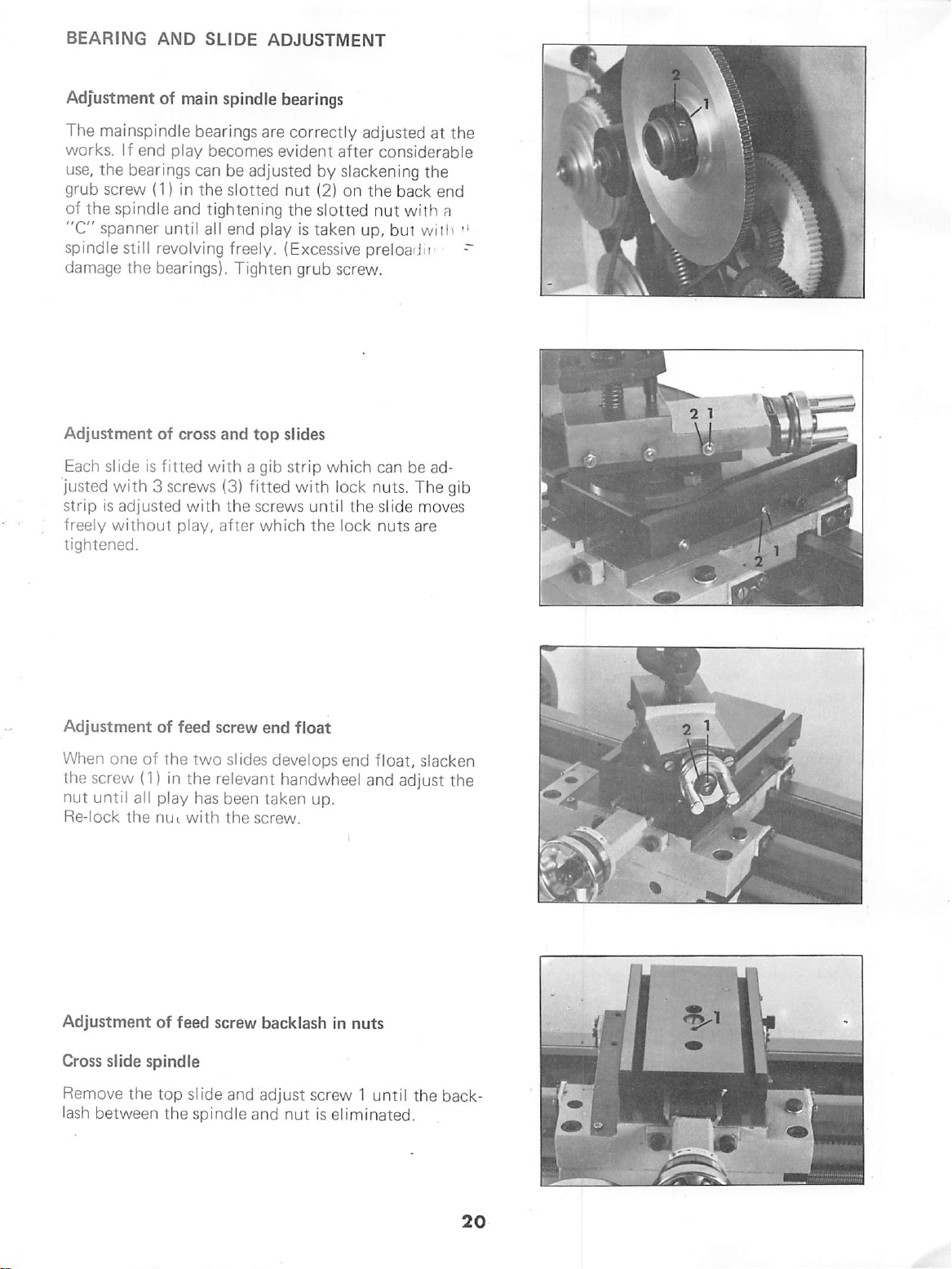
BEARING
AND
SLIDE
ADJUSTMENT
Adjustment
The
mainspindle
works.
use,
the
grub
screw
of
the
"C"
spanner
spindle
damage
Adjustment
Each
slide
justed
strip
is
freely
tightened.
of
If
end
play
bearings
(1)
spindle
until all end
still revolving
the
bearings).
of
is
fitted
with 3 screws
adjusted
without
main
spindle
bearings
becomes
can
be
in
the
slotted
and
tightening
freely.
Tighten
cross
and
with a gib
(3)
with
the
play,
after
bearings
are
correctly
evident
adjusted
play
top
fitted
screws
which
by
nut
(2)
the
slotted
is
taken
(Excessive
grub
slides
strip
which
with
until
the
adjusted
after
considerable
slackening
on
the
nut
up,
at
the
back
with
but with
preloadn'
screw.
can
be
ad
lock
nuts.
The
the
slide
moves
lock
nuts
are
the
end
a
"
~
gib
Adjustment
When
one
of
the
screw
(1)
nut
until all play
Re-lock
Adjustment
Cross
Remove
lash
the
slide
spindle
the
between
of
feed
the
in
nui
of
feed
top
the
the
with
screw
two
slides
relevant
has
been
the
screw
slide
and
spindle
and
end
float
develops
handwheel
taken
up.
screw.
backlash
adjust
screw 1 until
nut
is eliminated.
end
in
nuts
float,
slacken
and
adjust
the
the
back
Page 22
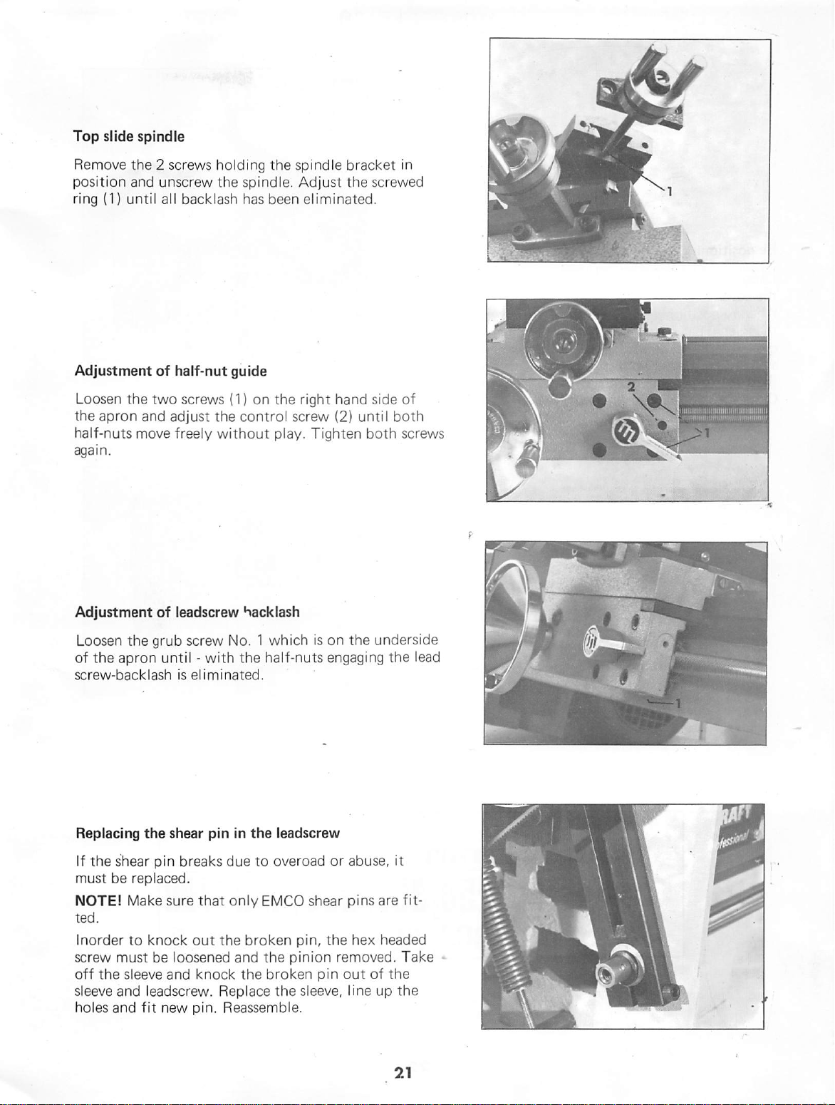
Top
slide
spindle
4/
Remove
position
ring
Adjustment
Loosen
the
half-nuts
again.
the 2 screws
and
(1)
until
the
two
apron
and
move
unscrew
all
backlash
of
half-nut
screws
adjust
freely
holding
the
spindle.
has
guide
(1)
on
the
control
without
the
spindle
Adjust
been
eliminated.
the
right
screw
play.
Tighten
bracket
the
screwed
hand
side
(2)
until both
both
in
of
screws
Adjustment
Loosen
of
the
screw-backlash
Replacing
If
the
must
be
NOTE!
ted.
Inorder
screw
off
the
sleeve
holes
and
of
the
grub
apron
shear
must
and
until -
the
pin
replaced.
Make
sure
to
knock
be
sleeve
leadscrew.
fit
new
shear
and
leadscrew
screw
is
eliminated.
breaks
that
out
loosened
knock
pin.
hacklash
No. 1 which
with
the
pin
in
due
only
the
and
the
Replace
Reassemble.
half-nuts
the
leadscrew
to
overoad
EMCO
broken
pin,
the
pinion
broken
the
sleeve, line
is
on
the
engaging
or
abuse,
shear
pins
the
hex
removed.
pin
out
underside
the
lead
it
are
fit
headed
Take
of
the
up
the
Page 23
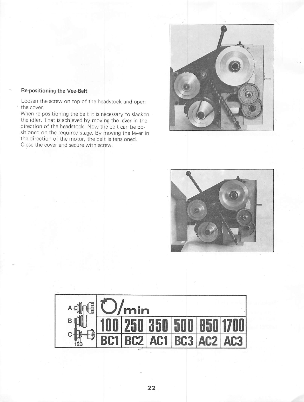
Re-positioning
the
Vee-Belt
Loosen
the
When
the
direction
sitioned
the
Close
the
screw
cover.
re-positioning
idler.
That
of
the
on
the
direction
the
cover
on
top
the
belt
is
achieved
headstock.
required
of
the
and
stage.
motor,
secure
of
by
Now
the
with
the
headstock
it
is
necessary
moving
By
the
moving
belt
is
screw.
the
belt
tensioned.
and
open
to
slacken
lever
in
can
be
the
lever
the
po
in
^3/min
100
BC1
250
BC2
AC1
BC3
AC2
AC3
Page 24

Page 25

Wiring
Diagram
"EMCO
COMPACTS"
"M
r'
O
3
J
R
O
Mp
SI
1
6
10
^612
11
J
k1
b1
k1
ml
m
1
Motor
switch
Condenser
Motor
o'
O
black
w
blue
grey
u
C>
(>—
brown
..
J
Motor
forward
hi
—
switch
diagram
123
—
—
4
X X
—
9
10
X
11
12
X
—
—
7
5
8
6
—
—
0
—
reverse
—
X
—
—
—
—
—
—
X
—
X
X
24
Page 26

Mounting
of
Vertical
Milling
and
Drilling
Unit
COMPACT
Technical
8
Data
Motor;
lEC-standard
and
splashproof
Input
Output
For
on
Spindle
5o
6o
Spindle
power
power
voltage
motor.
speeds;
cycles:
cycles:
nose
single-phase
according
(PI)
2oo
W,
(P2)
loo
W,
and
frequency - see
38o/7oo/16oo
45o/8oo/19oo
(main
spindle)
motor,
to
IP
44
S3-6o % ID
S3-6o % ID
label
rpm.
rpm.
:
dust
O
CN
82(3.22"
according
M14 X 1
Weight:
For
dimensions
Electrical
The
vertical
may
only
grounding
tical
of
the
Mounting
Due
to
different
not
delivered
Mounting
professionally!
Clamp
to
the
Clamp
and
N.
to
thread.
6,5
kg
Connection
be
plugged
contacts
must
be
machine)»
the
the
different
countries,
of
plugs
tdie
grounding
grounding
the
other
factory
(14
pounds)
-
refer
milling
(a
available
plug;
with
must
contact
two
standard,
to
sketch
and
drilling
into
outleds
grounding
for
requirements
the
machines
plugs
everywhere.
be
carried
wire
(yellow-green)
(symbol@
wires
to
with
unit
with
recep-
connection
in
are
out
contact
).
R
25
Page 27

Accident
Prevention:
Milling
-
Drilling
+ Always
prevention
Additional
+ Clamping
When
drilling
piece
order
being
of
Clamping
ing
chuck,
+
Work
sharpened
+ Clpse
■ machine.
+ Remove
ly
is
+ Loose
must
to
loosened
the
table
only
belt
with
not
clothing
pecially
can
easily
grooves
follow
on
tips;
the
be
the
page
workpiece
or
clamped
prevent
by
tool.
tools:
with
clamping
4-jaw
independent
with
perfectly
tools!
cover
milling
brush
switched
and
and
and
dangerousi
get
caught
of
the
millers
rules
1!
milling,
the
workpiece
the
machine
before
drilling
only
on.
hairs
Hair
in
for
accident
the
work-
securely,
cutting
vice,
force
mill
shoes,
chuck
ground
switching
chips
when
machine
can
be
or
clothing
the
spiral
and
drills.
in
from
3-jaw
...
and
on
on
es
+ Never
+ Never
ning.
+ The
clamped
circular
in
the
Note:
To
enable
milling
drawings.
however.
wear
clean
milling
so,
saw
uppermost
better
guard
The
rings
machine
guard:
that
blade)
is
guard
when
working!
while
the
the
is
position.
illustration,
not
must
ring
tool
covered
shown
be
it
must
(miller,
in
mounted,
is
some
run
be
when
the
Note;
The
vertical
is
also
used
Therefore
tions
are
of
valid
milling
on
the
you
will
the
Compact 8 if
for
both
Compact
find
machines.
26
and
drilling
same
unit
5.
illustra
informations
Page 28

TO
255(10")
Mounting
of
Vertical
Milling
o
and
1.
If
tdie
please
rough
Drilling
there
rear
prepare
holes).
are
side
Upit
no
threaded
of
the
threaded
holes
machine
holes
at
bed,
(tho
in
cd'
='
70
90
ir
■o
2.76"
3.54"
10
.39".
Pre-drilling
4
mm
dia.
Pre-drilling
6,5
mm
dia.
Note:
If
the
bores
taps
ded
the
Get 2 cap
are
holes,
illustration.
lo-24x6/8")
not
make
screws
to
and 4 hexagonal
(pos.3)
and
drilling
to
mount
threaded
threaded
are
not
available
inch
(Allen
mount
bolts
the
unit.
hole
M5:
hole
M8:
machined
to
make
bores
as
screws,
the
adaptor
5/16"-18x1
vertical
and
the
shown
pos.l)
plate
3/4"
milling
metric
threa
in
27
Page 29

2.
Screw
gonal
tighten
3.
Adjusting
tion
(pos.2)
rectangular
4.
Mount
using
and
to
be
on
support
screws
the 4 threaded
base
too
the
such
bracket
M5x20
firmly.
support
that
to
cross
the 4 hexagonal
washers.
The
rectangular
plate
(pos.1);
plate:
bolts
support
slide.
of
vertical
screws
vertical
to
the
with 2 hexa
do
not
posi
M8xl6
plate
is
unit
M8x40(Pos3^
column
cross
slide.
has
700
210
r—
4.1.
4.2.
Rectangular
nally
the
ded
to
cross
support
bolts
Rectangular
ly
to
cross
bracket
of
adjustment
slide:
plate
(pos.2).
adjustment
slide:
vertical
adjusting
using
clamp
unit
longitudi
the 4 threa
transversal-
base
at
90°
angle.
28
Page 30

Operating
Elements
Height
Loosen
clamping
unit
height.
adjustment
the
head
into
The
cross
5o
mm
(1.96") . By
cal
unit
match
cross
the
slide
Swivelling
socket
the
in
the
quill
and
turning
head
and
bring
required
slide
throat
different
working
travel.
holder
the
vertical
screw
position
clamping
the
vertical
is
angles,
on
the
and
limited
the
requirements
unit
verti
you
to
to
can
the
Moving
Insert
ling
A
to
Clamping
The
The
The
rate
drilling
Mounting
1.
the
toggle
the
built-in
the
original
quill
Always
never
Vertical
vertical
depth
Loosen
toggle
onto
toggle.
quill
into
toggle,
spring
screw
for
is
fixed
clamp
force
Fine
fine
adjustment
operations.
set
screw
(2)
and
the
pinion
the
bore.
the
quill
returns
position.
the
quill
with
quill
the
toggle.
the
(3)
the
when
Feed
feed
serves
for
milling
(1), pull
mount
worm
(4), re-tighten
By
swivel
is
lowered.
quill
socket
milling,
in
head
Attachment
for
accu
and
out
wheel
(3)
Loosen
the
The
positioning.
socket
quill
graduated
Through
movements,
>;•:
any
required
head
holder
scale
these
the
screw
to
the
enables
turning
quill
angle.
(1)
and
required
accurate
and
swivelling
can
be
set
swivel
angle.
at
2.
3.
.unit
Insert
Place
into
the
socket
worm
wheel
pinion
centering
into
the
bore
head
is
engaged with
the
bolt
and
screw,
quill
(5)
clamp
so
of
that
holder.
the
with
the
feed
the
worm.
Page 31

If
the
sion,
If
loosen
Worm
The
worm
the
quill
the
fine
socket
and
pinion
(6)
feed
worm
can
is
turned
moves
is
head
wheel
be
o,l
not
screw
are
moved
by
one
mm.
required,
and
not
engaged
with
divi
swivel
the
Adjusting
Open
cover
(2)
and
The
belt
onto
the
Tighten
the
(1),
swivel
is
loosened
required
belt
and
again.
Note;
Never
work
with
Spindle
loosen
motor
fix
belt
socket
toward
and
pulley
socket
cover
Speed
head
the
front.
can
be
shifted
combination.
head
screw
opened
1
screw
Spindle
The
spindle
drilling
the
tool
of
workpiece
The
values
for
sharpened
Diameter
miller
drill
to
5-10
10-15
15-20
20-40
or
(mm)
5
Speed
speed
depends
{miller,
material.
shown
tools.
of
SPINDLE
Steel
1600
during
on
drill)
below
700
700
380
380
the
SPEED
Chart
milling
diameter
and
are
valid
Cast
1600
700
380
380
380
the
Iron
and
of
type
only
Aluminium/
Brass
1600
1600
700
700
380
Page 32

Clamping
Devices
for
Drills
(Summary)
and
Millers
3-jaw
drill
Spiral
Centering
Countersunk
drill
chuck
drill
Collet
(not
the
with
the
Millers
and
attachment
same
as
lathe)
fly
cutter
Millers
Arbor
with
I
I
16
mm
bore
31
Page 33

Tighten
Note:
from
the
tion,
clamping
if
you
top,
however,
look
the
looks
nut
(3)
at
the
tightening
counterclock
clockwis
clamping
dire
Clamping
It
is
mounted
Collet
The
onto
Clamping
25:
Attachment
collet
the
1,5 - 14
Millers
with
highest
this
reason,
necessary.
by
means
ded.
Mounting
-
Insert
that
the
tioned
-
Mount
capacity
holder
spindle
capacity
must
be
round-run
the
Clamping
of
the
The
ESX-25
the
groove
in
the
nut
with
1-8
directly
is
nose.
using
mm
clamped
collet
is
pins
collet
of
ring
collet
mm
(o.o4"-o.3")
onto
mounted
the
securely
accuracy.
attachment
accomplished
which
collets:
in
the
the
(2)
are
collet
of
on
the
directly
collets
and
For
inclu
nut
(2)
is
the
nut.
the
holder.
spindle
ESX
is
so
posi
Dismounting
Open
nut.
The
collet
the
ring
of
Nominol
dio.
The
clamping
the
collet.
Do
not
clamp
catalog)
the
collets:
is
automatically
the
nut.
Individual
in
mm
Chucking
copocily
capacities
other
collets
in
ESX-25
mm
Shaft
dio-
Vf,
'V6<-'/33-IV64
^/33-'Vg.-Vl6
2
Vs.- I V33
?V6.-3/9-"/sr~
'V3:-"/6.
3V6.-V3
33/a.-l'/33-3V6<
are
diameters!
ejected
in
Inches
engraved
(See
by
on
also
The
It
serves
circular
and
millers with
bore
of
milling
saw
16
for
mm
arbor
mounting
blades
a
(o.63")
.
Page 34

Clamping
Devices
for
Workpieces
1.
Machine
Width
Opening:
It
shers
is
of
mounted
and
vice:
jaws:
60
5o ram
mm
(2.36")
with
hexagon
(2.36")
the
nuts
T-nut
to
the
bolts,
cross
wa
slide
3.Clamping
ing
chuck
Mount
-
Mount
smaller
xagonal
chuck
support
with
to
T-nut
nuts
or
to
the
self-center
independent
the
support
plate
bolts,
the
with
washers
cross
plate
the
slide.
two
and
chuck
he
2.
Stepped
Clamping
Workpieces
cross
must
height
slide.
be
used
clamping
up
to
2o
are
clamped
At
least 2 clamping
for safe
clamping.
shoes;
mm
(.8")
directly
to
shoes
the
Page 35

Drilling
in
Generai
Clamping
Drills
or
in
the
Clamping
The
workpiece
or
on
the
the
appropriate
Spindle
The
spindle
on
the
ler
and
Drill
Drill
feed;
feed
the
drill
are
clcimped
collet
the
workpiece
dividing
speed:
speed
diameter
the
material
is
in
chuck.
is
fixed
attachment,
clamping
of
of
the
achieved
the
on
the
drill,
of
the
via
drill
the
top
device.
drill
resp.
workpiece.
the
chuck
slide
using
depends
mil
quill.
The
smaller
it
is
that
it
feed
must
be
feeling
Coordinate
With
longitudinal
wheels,
dinates
(very
aid
of
drilling
can
drilling
Please_note:
The
scale
to
the
during
cross
2,5
mm
tion.
ly
1,25
on
diameter
turning.
slide
after
The
slide,
mm.
the
drill,
will
carried
carefully)
the
scale
and
cross
in
be
carried
the
cross
of
The
handwheel
one
complete
however,
the
break.
out
.
rings
slide
accurate
out.
slide
the
workpiece
scale
indicates
Working
easier
Drill
with
on
the
hand-
coor
refers
on
the
revolu
moves
on
Tips - Driiiing
Place a wooden
der
the
workpiece
ing
table,
not
damaged
Use
the
vertical
rate
depth
When
drilling
drill
so
A
the
crease
Wear
edges
Re-sharpen
that
few
friction
of
out
drilling
drops
the
the
of
or
machine
by
the
adjustments.
deep
of
the
of
oil
of
the
tool's
drill
the
main
drill
plastic
so
that
vice,
drill.
fine
holes,
bore
chips
will
drill
life.
can
cutting
in
time.
board
the
etc.
feed
for
pull
regularly,
are
removed.
decrease
and
first
be
surface.
un
mill
are
accu
the
in
seen
34
Page 36

Milling
In
General
Types
Main
The
movement.
miller
move
of
or
working
miller
penetrate
material.
Adjustments
Adjustment
Feed
movement
Accomplised
Example:
-
Main
movement
-
Adjustment
-
Adjustment
-
The
feed
nal
slide
Movements
movement
does
the
main
The
cutting
the
of
milling
by
the
workpiece.
is
made
by
the
cross
by
the
quill
movement
(1)
by
or
working
edges
workpiece
depth
by
slide
(t)
the
of
or
miller.
longitudi
the
and
re
width.
(b)
Climb
Conventionai
(up-miiling
Climb
Cutting
feed
the
Milling
milling
direction
direction
same.
(downcut
Milling
process)
of
of
the
the
milling)
miller
workpiece
and
are
r"^
Conventional
Cutting
feed
direction
opposite.
Working
Use
conventional
on
the
there
miller.
milling
direction
tip;
Compact
is
danger
of
of
the
milling
5,
otherwise
of
the
miller
workpiece
method
breaking
and
are
the
35
Page 37

Working
Tips - il/iiiiing
Example
1
Milling a notch
mill.
- Set
- Clanp
- Loosen
milling
clamp
slide
slide.
mill
the
quill.
longitudinal
feed
to
longitudinal
length
with
depth
width
"1"
the
"t"
slide
"b".
slide
of
Clamping
Tighten
that
heavy
with
the
with
Clamp
clamping,
the
notch.
of
duty
quill,
cross
cross
points
all
clamping
the
feed
facilities,
movement.
Example
Milling a groove
cutter.
- Adjust
slide,
- Using
clamp
- Using
the
length
except
2
with
center
clamp
quill,
quill.
longitudinal
cross
mill
"1"
of
of
the
axis
slide.
depth
slide
the
grooving
using
of
groove,
feed
groove.
the
mill
cross
36
The
heavy
the
face
miller
then
cannot
move
rection,
center
and
duty
mill
has a bore
surface.
in
'For
be
inserted
longitudinal
since a plug
prevents
any
this
reason
in
or
remains
feed.
on
bore
cross
in
the
this
and
di
Page 38

Milling
If
feed
will
depth - milling
the
milling
are
bend - this
breaking
When
hard
load
is
rials
.
For
this
too
large/fast/
and
overloading
materials
larger
reason^
feed
depth
means
than
and
danger
are
with
the
the
the
used/
softer
milling
miller
of
machine.
the
mate
Complete
ing
with
Selecting
The
selection
pends
resp.
workpiece.
0
1
m
In
-
-
on
drill
General^
The
the
slower
The
piece,
the
the
larger
harder
the
Spindle
of
the
diameter
and
not
the
diameter
the
spindle
the
material
Slower
the
deep
steps.
feeling.
Speeds
spindle
of
the
on
the
speed.
spindle
Feed
speeds
miller
size
of
the
of
the
grooves
must
de
of
the
miller,
work-
speed.
in
be
several
carried
work
out
Diametpf
or
drill
to
5
10-15
15-20
2o-4o
cf
(mm)
miller
SPINDLE
Steel
16oo
7oo
7oo
38o
38o
SPEED
37
Cast
16oo
7oo
38o
38o
38o
Iron
Aluminium/Brass
16oo
16oo
7oo
7oo
38o
Page 39

Wiring
and
Diagram
Driliing
Ul
for
Miiiing
Unit
SI
o
Z2
II
k1
IF
m1
38
Page 40

Page 41

Grundausstattung
Tools
Equipement
de
base
Pos
6
7
8
1
2
3
4
5
Ref.No.
2WZ
B2A
ZW2
B1A
B1A
ZMU
B2A
B2A
ZSR
B2Z
11
000
99
140
140
34
130
130
33
200
0500
470
0012
000
010
0800
000
010
0840
070
DIN
M8
DIN
M8x40DIN
934
933
BENENNUNG
Sechskantstiftschliissel
Ring • Maulschliissel
Klelnfettpresse
G.
Mitnehmer
Mitnehmerbolzen
Sechskantmutter
G.
Drehherz
Drehherz
Sechska
ntsch
rau
be
Wechselrad z =
60
DESCRIPTION
Hexagonal
Key
wrench
Grease
gun
Holding
bolt
Holding
bolt
Nut
Lathe
dog
Lathe
dog
Hexagon
Change
screw
gear
key
016
coud6e
016
connbin6e
Petite
pompe 6 graisse
Ensemble
Pousse-toe
Ecrou
hexagonal
Toe
de
tour
Toe
de
tour
Vis
tete
hexagonale
Engrenage
DESIGNATION
pour 6 pans
plate
et a oeil
pousse-toc
complet
seul
creux
Page 42

Diehmaschinenbett
Lathe
bed
Banc
Pos
10
11
12
13
14
15
16
DESIGNATION
nu
Vis-mere
tete
cylindrique
t^te
cylindrique
hexagonal
grover
hexagonal
metr.
pans
creux
USA
vis-mere
(droite)
(gauche)
be
DESCRIPTION
Bed
Rack
Lead
screw
Lead
screw
Bearing
block
Bearing
block
Grease
fitting
Nut
Set
screw
Allen
head
Flat
head
screw
Allen
head
Nut
Clip
Stud
Nut
Stud
metr.
screw
screw
Banc
Cr^mailiere
Vis-mere
USA
Paliersupportdevismere
Palier-supportde
Graisseur
Ecrou a 2
Contre-vis
Vis
Vis
Vis 6 pans
^crou
Rondelle
Goujon
icrou
Goujon
Ref.No.
1
B1A
000
030
2
B2A
000 020
3
B1A
000 070
B1B
000
070
4
B1A
000
221
5
B2A
000
030
6
ZNP
01
1000
7
B2A
000
100
8
ZST
51
0806
ZSR
12
84
12
34
28
39
34
39
0630
0410
0630
0600
0060
0620
0800
0825
9
ZSR
ZSR
ZMU
ZRG
ZSR
ZMU
ZSR
DIN
M8x6
DIN
M6x30DIN
M4x10DIN
M6x30DIN
M6
DIN
B6
DIN 127
M6x20DIN
M8
DIN
M8x25DIN
551
912
84
912
934
939
934
939
BENENNUNG
Bett
Zahnstange
Leitspindel
Leitspindel
metr.
USA
Spindeltrager
Leitspindeltrager
Schmiernippel
Mutter
Gewindestift
Innensechskantschraube
Zylinderschraube
1 n nensechskantsch
Sechskantmutter
rau
Federring
Stiftschraube
Sechskantmutter
Stiftschraube
Page 43

121110
9
8
7
4
5
6
13
Page 44

B1A
030
000
G.
Spindelstock
Headstock
Poup6e
fixe
Pos
4
6
8
9
10
11
12
13
1
2
3
5
7
Ref.No.
B1A
B1A
ZFD
B1A
ZLG
81A
81A
81A
81A
82A
ZST
82A
ZST
030 010
030
020
85
8536
030
050
0076
32
030
060
030 040
030
030
030
070
030
060
17
0405
030
070
51
0410
DIN
A8x5x36
32007XC/P6
M4x5
DIN
M4x10
DIN
DIN
417
551
6885
BENENNUNG
Spindelstock
Spindel
PaBfeder
Dichtscheibe
Kegelrollenlager
Deckel
Distanzhulse
Zahnrad
Riemenscheibe
Druckscheibe
Gewindestift
Spannmutter
Gewindestift
DESCRIPTION
Headstock
Spindle
Key
Gasket
Heavy
taper
Cover
8ushing
Gear
Pulley
Disc
Set
screw
Nut
Set
screw
roller
bearings
DESIGNATION
Carter
de
poup^e
fixe
8roche
principale
Clavette
Disque
d'etancheite
Roulement 3 rouleaux
8ouchon-cuvette
Entretoise
Engrenage
Poulie
de
broche
Pastille
de
pointeau
Vis
pointeau
Ecrou
canele
Goujon
coniques
Page 45

m
28
30
31
l
i
i
i
i! i>>.
Page 46

Antrieb
Drive
Entrainement
Pos
6
8
9
10
11
12
13
14
15
16
17
18
19
20
21
22
23
24
25
26
27
28
29
30
31
32
33
34
35
36
37
38
39
40
1
2
3
4
5
7
81A
81A
ZSR
ZRG
ZS8
ZSR
ZSR
ZS8
81A
BIB
ZSR
81A
81A
ZSR
ZNP
ZRG
ZS8
81A
82A
81A
ZKG
81A
ZLG
ZRG
81A
ZRM
ZRM
ZS8
ZRG
ZMU
ZSR
ZRG
81A
81A
81A
81A
81A
ZSR
ZS8
C3A
81A
ZSR
81A
ZMU
Ref.No.
060
000
12
28
25
63
84
25
000
000
84
210
000
12
01
71
10
211
030
000 090
00
000
77
71
000
45
51
25
28
34
12
28
000
215
000
000
000
12
21
062
000
12
000
34
000
060
0612
ooSo
0640
0512
0508
0530
180
180
0406
000
210
0820
1000
1210
2181
000
130
1060
340
2542
2512
320
0690
7170
1050
0100
1000
0520
0050
100
000
080
130
120
0620
0640
040
050
0622
110
0600
M6x12DIN
86
DIN 127
86,4
DIN
M5x12
M5x8
85,3
DIN
M4x6
M8x20
12x1
DIN
22x18x1
6,0GK3
AS
2542
25x1,2
Gates
5M-690
170XL
810,5
810
DIN
M10
DIN
M5x20
85
DIN
M6x20
A6,4
DIN
M6x22
M6
DIN
DIN
DIN
DIN
DIN
DIN
DIN
DIN
050
DIN
DIN
127
DIN
DIN
125
84
125
84
471
125
127
934
9021
934
963
912
5401
471
912
912
912
912
BENENNUNG
G.
Deckel
Abdeckblech
Zylinderschraube
Federring
Scheibe
Senkschraube
Zylinderschraube
Scheibe
Frontschild
Frontschild
metr.
USA
Zylinderschraube
G.
Tragerplatte
Tragerplatte
Zylinderschraube
Schmiernippel
Sicherungsring
Stutzscheibe
G.
Kupplung
Bundlager
Vorgelegeriemenscheibe
Stahlkugel
Druckfeder
Axiallagerscheibe
Sicherungsring
Kupplungsriemenscheibe
Keilriemen
Zahnriemen
Scheibe
Federring
Sechskantmutter
Zylinderschraube
Federring
Scheibe
G.
Motorriemenscheibe
Motorriemenscheibe
Aniaufring
Aniaufscheibe
Zylinderschraube
Scheibe
Druckfeder
Klemmleiste
Zylinderschraube
Riemenscheibenwelle
Sechskantmutter
DESCRIPTION
Cover
Covermount
Round
head
Clip
Washer
Flat
head
screw
Round
head
Washer
Plate
metr.
Plate
Round
Bracket
Bracket
Round
Grease
USA
head
plate
plate
head
nipple
screw
screw
Clips
Washer
Clutch
Bearing
bush
Countershaft
Ball
Feed
spring
Thrust
bearing
Clip
Belt
pulley
Vee
belt
Drive
belt
Washer
Clip
Nut
Round
head
screw
Clip
Washer
Pulley
Pulley
Start
sleeve
Spacer
Round
head
screw
Washer
Feed
spring
Clamp
piece
Round
head
screw
Belt
pulley
shaft
Hexagon
nut
screw
screw
pulley
washer
DESIGNATION
Couvercle
T6le
Vis
Rondelle
Rondelle
Vis
Vis
Rondelle
Plaque
Plaque
Vis
Plaque
Plaque
Vis
Graisseur
Circlip
Rondelle
Embrayage
Palier
Poulie
crantee
Bille
Ressort
Disque
Circlip
Poulie
Courroie
Courroie
Rondelle
Rondelle
Ecrou
Vis
Rondelle
Rondelle
Poulie
Poulie
Douille
Disque d rainure
Vis
Rondelle
Ressort
Lardon
Vis
Arbre
Ecrou
assemble
de
couverture
tSte
cylindrique
grover
plate
tdte
fraisee
tete
cylindrique
grover
frontale
frontale
t§te
cylindrique
support
assemblee
support
seule
t^te
cylindrique
plate
assemble
d'assemblage
de
renvoi
acier
de
compression
trapezoidale
trapezoidale
crantee
plate
grover
hexagonal
tete
cylindrique
grover
plate
epaul^e
moteur
assemblee
moteur
seule
entretoise
tSte
cylindrique
plate
de
compression
de
blocage
t§te
cylindriques
des
poulies
hexagonal
pour
metr.
USA
courroie
de
I'embrayage
de
clavette
1
'
<
.
;
Page 47

19 9 18
n
17
7 5 6
12
13
8
1415
Page 48

Riemenspanner
Tensioning
roller
Rouleau
tendeur
Pos
1
2
3
4
5
6
7
8
9
10
11
12
13
14
15
16
17
18
19
81A
81A
ZGF
81A
81A
81A
ZST
ZRG
81A
ZRG
81A
81A
ZS8
ZRG
ZS8
ZMU
81A
ZS8
ZS8
ZNP
Ref.No.
213
000
20
190
212
000
16
71
214
71
000
000
02
71
25
34
000
12
10
01
000
160
3212
000
000
310
0812
0607
000
1210
150
170
6204
3717
1050
1000
290
2601
2181
1000
KK32-12
AM
8x12
6x0,7
12x1
DIN
6204/K2
37x1,75
810,5
Ml0
DIN
PS
26x37x1
88
12x18x1,2
DIN
DIN
DIN
DIN
DIN
471
471
125
934
471
916
BENENNUNG
G.
Hebel
Hebel
Kugelknopf
G.
Spannhebel
G.
Drehbolzen
Hiilse
Gewindestift
Sicherungsring
G.
Spannrolle
Sicherungsring
Zugfeder
8olzen
Ausgleichscheibe
Sicherungsring
Scheibe
Sechskantmutter
Scheibe
PaKscheibe
Stiitzscheibe
Schmiernippel
DESCRIPTION
Lever
Lever
Plastics
ball
Lever
8olt
Sleeve
Set
screw
Clip
Roller
Clip
Spring
8olt
Washer
Clip
Washer
Nut
Washer
Washer
Washer
Grease
nipple
DESIGNATION
Levier
Levier
Sphere
Levier
Sou
Ion
Manchon
Vis
pointeau
Sague
fendue
Rouleau
Bague
fendue
Ressort
Soulon
Rondel
Sague
fendue
Rondelle
Ecrou
Rondelle
Rondelle
Rondelle
Graisseur
de
matiere
de
traction
le
comprimee
Page 49

m
10
Page 50
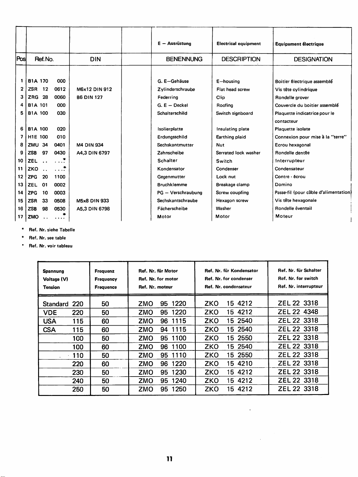
E — Ausriistung
Electrical
equipment
Equipement
^lectrique
Pbs
2
3
4
5
6
7
8
9
10
11
12
13
14
15
16
17
M6x12
B6
DIN
M4
A4,3
M5x8
A5,3
DIN
DIN
DIN
DIN
DIN
DIN
127
934
912
6797
933
6798
Ref.
No.
1
B1A
170
000
ZSR
12
0612
28
101
100
100
100
Nr.
Nr.
Nr.
0060
000
030
020
010
34
0401
97
0430
*■
20
1100
01
0002
10
0003
33
0508
0530
98
siehe
Tabelle
see
table
voir
tableau
ZRG
B1A
B1A
B1A
HIE
ZMU
ZSB
ZEL
ZKO
ZPG
ZEL
ZPG
ZSR
ZSB
ZMO
Ref.
Ref.
Ref.
BENENNUNG
G.
E—Gehause
Zyiinderschraube
Federring
G. E —
Deckel
Schalterschild
Isolierplatte
Erdungsschild
Sechskantmutter
Zahnscheibe
Schalter
Kondensator
Gegenmutter
Bruchklemme
PG — Verschraubung
Sechskantschraube
Facherscheibe
Motor
DESCRIPTION
E—housing
Flat
head
screw
Clip
Roofing
Switch
signboard
Insulating
Earthing
Nut
Serrated
Switch
Condenser
Lock
Breakage
Screw
Hexagon
Washer
Motor
plate
plaid
lock
nut
clamp
coupling
screw
washer
DESIGNATION
Boitier
§lectrique
Vis
t§te
cylindrique
Rondelle
Couvercle
Plaquette
contacteur
Plaquette
Connexion
Ecrou
Rondel
Interrupteur
Condensateur
Contre - 6crou
Domino
Passe-fil
Vis
Rondelle
hexagonal
le
fpour
tete
hexagonale
grover
du
indicatrice
isolate
pour
dent§e
§ventail
Moteur
assemble
boitier
mise a la
cable
d'alimentation
assemble
pour
le
"terre"
:
|
^
Spannung
Voltage
Tension
Standard
VDE
USA
CSA
(V)
220
220
115
115
100
100
110
220
230
240
250
Frequenz
Frequency
Frequence
50
50
60
60
50
60
50
60
50
50
50
Ref.
Ref.
Ref.
ZMO
ZMO
ZMO
ZMO
ZMO
ZMO
ZMO
ZMO
ZMO
ZMO
ZMO
Nr.
Nr.
Nr.
fiir
Motor
for
motor
moteur
95
95
96
94
95 1100
96
95 1110
96 1220
95 1230
95
95 1250
1220
1220
1115
1115
1100
1240
Ref.
Ref.
Ref.
ZKO
ZKO
ZKO
ZKO
ZKO
ZKO
ZKO
ZKO
ZKO
ZKO
ZKO
Nr.
Nr.
Nr.
fiir
Kondensator
for
condenser
condensateur
15
4212
15
4212
15
2540
15
2540
15
2550
15
2540
15
2550
15
4210
15
4212
15
4212
15
4212
Ref.
Ref.
Ref.
ZEL
ZEL
ZEL
ZEL
ZEL
ZEL
ZEL
ZEL
ZEL
ZEL
ZEL
Nr.
fiir
Nr.
for
Nr.
interrupteur
22
22
22
22
22
22
22
22
22
22
22
Schalter
switch
3318
4348
3318
3318
3318
3318
3318
3318
3318
3318
3318
11
Page 51

12
Page 52

Raderschere
Quadrant
Lyre
Pos
10
11
12
13
14
15
16
17
18
19
3
4
5
6
7
8
g
1
2
Ref.No.
B1A
ZSR
B2A
B2A
B2A
B2A
B2A
B2A
ZSR
B2Z
B2A
B1A
B2Z
B2A
B2A
B2A
B1A
B1A
ZNP
000
010
12
0630
000
300
000
310
000
350
000
270
000
280
000
450
33
0610
200
010
000
270
000
190
200
020
000
310
071
020
071
040
000 020
000
040
01
1000
M6x30
M6x10
DIN
DIN
DIN
912
933
BENENNUNG
Schere
Zylinderschraube
Scheibe
Keilhiilse
Scherstift
Wechselrad
80
Zwischenring
Sicherungsring
Sechskantschraube
Wechselrad
Wechselrad
Zahnrad
Wechselrad
Keilhiilse
Scheibe
Nutenstein
Scherbolzen
Scheibe
25
80
80
30
Schmiernippel
DESCRIPTION
Quadrant
Flat
head
Washer
Bush
Bushing
Gear
80
Bushing
Clip
Hexagonal
Gear
25
Gear
80
Gear
80
Gear
30
Bush
Washer
T-nut
Shaft
Washer
Grease
fitting
screw
screw
DESIGNATION
Lyre
nue
Vis
tetecylindrique
Rondelle
Douille • clavette
Goupille
Engrenage
Douille • entretoise
Rondelle
Vis
Engrenage
Engrenage
Engrenage
Engrenage
Douille - clavette
Rondelle
Ecrou
Boulon—axe
Rondelle
Graisseur
tSte
hexagonale
en
plate
de
cisaillement
80
dents
fer a cheval
25
dents
80
dents
80
dents
30
dents
plate
T
fer a cheval
13
Page 53

rn'ikl
rt'i
Page 54

700
010
G.
Radersatz
Set
of
change
gears
Jeu
d'engrenages
assembles
Pos
.
6
8
9
1
2
3
4
5
7
Ref.No.
B2A
B2A
B2Z
B2Z
B2Z
B2Z
B2Z
B2A
B2A
000
000
200
200
200
200
200
000
000
250
290
030
050
060
080
090
260
280
DIN
BENENNUNG
Wechselrad Z =
Wechselrad Z =
Wechselrad Z =
Wechselrad Z =
Wechselrad Z =
Wechselrad Z =
Wechselrad Z =
Wechselrad Z =
Zwischenring
DESCRIPTION
20
35
40
50
55
65
70
75
Change
Change
Change
Change
Change
Change
Change
Change
Bushing
gear
gear
gear
gear
gear
gear
gear
gear
DESIGNATION
Engrenage
Engrenage
Engrenage
Engrenage
Engrenage
Engrenage
Engrenage
Engrenage
Douille-entretoise
20
35
40
50
55
65
70
75
dents
dents
dents
dents
dents
dents
dents
dents
Pos
10
11
12
13
14
15
16
17
18
1
2
3
4
5
6
7
8
9
Ref.No.
B2A
B2A
B2A
B4A
B2A
B2A
B2A
HI
A
B2A
B2A
B2B
B2A
B2A
ZHL
ZSR
ZFD
ZRG
ZRG
ZKG
010
010
010
020
030
010
Oil
010
010 050
010
060
010
070
000
380
010
090
000
011
000
oil
000
012
000
013
81
0322
12
0630
93
2001
21
0100
0080
21
00
1040
DIN
3x22
DIN
M6x30
DIN
20x10,2x0,9
2093
WR
10
WR
8
4,0GK3
DIN
1481
912
DIN
5401
G.
SchloBplatte
BENENNUNG
SchloKplatte
Zwischenrad
Ritzel
Handrad
SchloBscheibe
Nachstellschraube
Fiihrungsschiene
Druckfeder
Einstellschraube
Gr.
SchloBmutter
Or.
SchloBmutter
Gr.
SchloBhebel
Gr.
Kegelgriff
Spannhiilse
Innensechskantschraube
Tellerfeder
Sprengring
Sprengring
Stahlkugel
Apron
DESCRIPTION
Apron
casting
Gear
Shaft
gear
Hand
wheel
Locking
cam
Adjusting
Guide
Feed
spring
Adjusting
Half
nut
Half
nut
Handle
Handle
Grooved
Allen
Spring
pin
head
washer
Clip
Clip
Ball
screw
screw
screw
Tablier
assemble
DESIGNATION
Tablier
nu
Pignon
double
Pignon
du
volant
Volant
Verrou
de
la
noix
Vis-pointeau
Languettes
Ressort
Vis-pointau
Noix = 2
Noix = 2
Levier
Manneton
Goupille
Vis
tete
Rondelle
Rondelle
Rondelle
Bille
de
de
de
compression
de
demi-noix
demi
d'enclenchement
assemble
fendue
six
pans
assiette
grower
grower
acier
intermediaire
r6glage
guidage
r^glage
noix
assemble
creux
15
Page 55

16
Page 56

Langs-
und
Querschlitten
Saddle
and
Cross
Slide
Trainard
at
chariot
transversal
Pos
6
8
10
11
12
13
14
15
16
17
18
19
20
21
22
23
24
25
26
27
28
29
30
31
32
33
34
35
36
37
38
39
41
2
3
4
5
7
9
1
Ref.No.
84A
B4A
B2A
828
82A
B4A
84A
84A
84A
82A
82A
82A
82A
82A
84A
ZSR
2ST
ZMU
ZKG
ZSR
ZSR
ZST
ZS8
ZSR
ZSR
ZS8
ZNP
ZSR
ZSR
ZSR
84A
848
84A
848
84A
82A
828
84A
848
82A
82A
82A
82A
ZFD
ZST
ZNA
ZSR
000
110
000
120
000
130
000130
000
180
000
170
000
180
000
190
000
200
000
660
000
150
000
140
000
210
000
220
000
240
63
0612
51
0412
34
0400
00
2316
12
0616
84
0408
08
0512
25
0530
33
0516
31
0635
25
0640
01
1000
12
0835
12
0630
12
0830
020
000
020
000
020 010
020 010
020
020
000 060
040 030
020
030
020 030
000
080
000 070
000
100
013
000
88
0337
51
0806
76
0144
12
0616
DIN
M6x12
DIN
M4x12DIN551
M4
DIN
934
3/16GK3
M6x16
DIN
M4x8
DIN
548x12
85,3
86,4
M5x16
M6x35
M8x35
M6x30
M8x30
3x3,7
M8x6
1,4x4
M8x16
DIN
DIN
DIN
DIN
DIN
DIN
DIN
DIN
DIN
DIN
DIN
DIN
'
963
DIN5401
912
84
7
125
933
931
125
912
912
912
6888
551
1476
912
BENENNUNG
Schlitten
Querschlitten
Quermutter
Quermutter
8ettleiste
Abstreifer
Abstreiffilz
Abstreifer
Abstreiffilz
Klemmstiick
Senkscheibe
Nachstellschraube
Einstelleiste
Druckstift
Deckblech
Senkschraube
Gewindestift
Sechskantmutter
metr.
USA
Stahlkugel
Innensechskantschraube
Zylinderschraube
Zylinderstift
Scheibe
Sechskantschraube
Sechskantschraube
Scheibe
Schmiernippel
Innensechkantschraube
Innensechskantschraube
Innensechskantschraube
G.Querspindel
G.Querspindel
Querspindel
Querspindel
metr.
USA
metr.
USA
Querspindeltrager
Skalenschlld
Skalenschild
Skalenring
Skalenring
metr.
USA
metr.
USA
8ogenfeder
Handrad
Mutter
Gr.
Kegelgriff
Scheibenfeder
Gewindestift
Kerbnagel
1 n nensechskantsch
rau
DESCRIPTION
Carriage
Cross-slide-table
Cross-slide-nut
Cross-slide-nut
Gib
Cover
Way
Cover
Way
Binding
Bushing
Adjusting
Gib
Stud
Cover
Flat
Set
screw
Nut
Ball
Allen
Flat
Flat
Washer
Hexagon
Hexagon
Washer
Grease
Allen
Allen
Allen
Lead
Lead
Lead
Lead
Lead
Plate
Plate
Micrometer
Micrometer
Spring
Handwheel
Nut
Handle
Key
Set
screw
Rivet
Allen
be
mount
cover
mount
cover
piece
mount
head
head
head
screw
fitting
head
head
head
screw
screw
screw
screw
screw
metr.
USA
head
screw
screw
screw
screw
head
head
screw
screw
screw
compl.
compl.
metr.
USA
mount
.
collar
collar
screw
metr.
USA
screw
screw
metr.
USA
metr.
USA
DESIGNATION
Trainard
Transversal
Noix
Noix
Languette
Plaquette
Racleur
Plaquette
Racleur
Plaque
Douille
Vis-pointau
Lardon
Cheville
T&le
Vis
Vis
Contre-^crou
Bijle
Vis
Vis
Cheville
Rondel
Vis
Vis
Rondelle
Graisseur
Vis
Vis
Vis
Broche
Broche
Broche
Broche
Support-pal
Plaquette
Plaquette
Vernier
Vernier
Lame
Volant
Ecrou 2 pans
Manneton
Clavette
Vis-pointau
nu
nu
du
transversal
du
transversal
de
couvre-racleur
en
feutre
couvre-racleur
en
feutre
de
blocage
fraisSe
de reglage
de
pression
de
recouvrement
t§te
frais6e
de
reglage
acier
t6te 6 pans
tdte
cylindrique
le
plate
tSte
hexagonale
t6te
hexagonale
plate
t§te 6 pans
t§te 6 pans
tdte 6 pans
de
commande
de
commande
de
commande
de
commande
ier
graduee
gradu^
metr.
USA
ressort
demi-lune
Rivet
Vis
t§te 6 pans
guidage
de
rgglage
creux
creux
creux
creux
de
courbe
de
reglage
creux
metr.
USA
du
transversal
du
transversal
du
du
broche
metr.
USA
r
I
transversal
transversal
r
I
17
Page 57

16—^
18
13
25
30
31
Page 58

G.
Obersupport
Compound
Chariot
superieur
Pos
10
11
12
13
14
15
16
17
18
19
20
21
22
23
24
25
26
27
28
29
30
31
2
3
4
5
6
7
8
9
1
Ref.No.
B4A
B2A
B2A
B2A
B2A
B2A
B2B
B2A
B4A
B2A
B2A
B2A
ZSR
ZSR
ZSR
ZST
ZMU
ZMU
ZHL
ZHL
B4A
B4A
B4A
B4A
B4B
B2A
B2B
B2A
B2B
B2A
828
B4A
B2A
ZFD
B2A
B2A
ZST
050
010
050
020
050 030
050
041
050
050
050
060
050
060
050
070
050
080
050
090
050
040
61
0830
84
0512
84
0610
51
0410
34
0400
34
0600
81
0212
81
0312
050
050
050
051
000
051
000
051
010
051
010
051
020
051
020
020
030
020
030
051
010
040
051
88
0337
080
000
000
100
51
0806
100
100
110
120
130
AM8x30
M5x12
M6x10
M4x10
M4
DIN
M6
DIN
2x12
3x12
3x3,7
M8x6
DIN
DIN
DIN
DIN
DIN
DIN
DIN
DIN
DIN
934
934
84
84
551
1481
1481
6888
551
561
BENENNUNG
Obersupport
Oberplatte
Einstelleiste
Klemmring
Skalenring
Obermutter
Obermutter
Einstellschraube
Schraube
Nutenschraube
Druckstift
Sechskantmutter
Sechskantschraube
metr.
USA
Zylinderschraube
Zylinderschraube
Gewindestift
Sechskantmutter
Sechskantmutter
Spannhiilse
Spannhijlse
Spannklaue
Ballenscheibe
Druckfeder
G.Oberspindel
G.Oberspindel
Oberspindel
Oberspindel
Oberspindeltrager
Oberspindeltrager
Skalenring
Skalenring
Handrad
metr.
USA
metr.
USA
metr.
USA
metr.
USA
Kegelgriff
Scheibenfeder
Bogenfeder
Mutter
Gewinde.-tift
DESCRIPTION
Compound
Swivel
base
Gib
Clamping
Micrometer
Lead
screw
Lead
screw
Adjusting
Screw
T-nut
screw
Stud
Nut
Hexagon
Flat
Flat
Set
Nut
Nut
Lock
Lock
Tool
Washer
Spring
Lead
Lead
Lead
Lead
Lead
Lead
Micrometer
Micrometer
Handwheel
Handle
Key
Spring
Nut
Set
head
head
screw
pin
pin
clamp
screw
screw
screw
screw
screw
screw
screw
head
screw
screw
ring
collar
nut
nut
screw
metr.
USA
metr.
USA
mount
mount
collar
collar
metr.
USA
screw
metr.
USA
metr.
USA
DESIGNATION
Chariot
superieur
Support-glissidre
Lardon
de
Bague
de
Embase
gradu^e
Noix
metr.
Noix
USA
Bague-ecrou
Boulon
de
Boulon
en
Cheville
Ecrou
hexagonal
Vis a t§te
Vis
tete
cylindrique
Vis
t@te
cylindrique
Vis-pointau
Contre-^crou
Ecrou
hexagonal
Goupille
Goupille
Bride
Rondelle
Ressort
Broche
assemblee
Broche
assemblee
Broche
Broche
fendue
fendue
de
serrage
spherique
de
du
du
nue
nue
Palier-support
Palier-support
Vernier
metr.
Vernier
USA
Volant
Manneton
Clavette
Lame
Ecrou 2 pans
Vis
ressort
de
reglage
demi-lune
nu
r^glage
blocage
de
r^glage
fixation
T
hexagonale
de
reglage
d'outil
compression
chariot
metr.
chariot
USA
metr.
USA
de
broche
de
broche
courhe
du
porte-outil
superieur
superieur
metr.
USA
19
Page 59

24
©
20
Page 60

G.
Reitstock
Tailstock
compl.
Poupee
mobile
assemblee
Pos
6
10
11
12
13
14
15
16
17
18
19
20
21
22
2
3
5
7
8
1
4
g
Ref.No.
B2A
B2B
B2A
B2B
B2A
B2A
B2B
B4A
B2A
B2A
B2A
B2A
B2A
B2B
B2A
B2A
B4A
B2A
B4A
ZST
B2A
ZFD
ZST
ZSR
ZNA
ZNP
B2A
040
010
040
010
040
020
040
020
040 030
000
060
040
030
010
040
040
050
040 060
040 070
080
040
000
OSO
020
030
080
000
100
000
041
000
010
041
020
041
17
0630
000
013
88
0337
0806
51
0650
31
0144
76
01
1000
090
040
M6x30
3x3,7
M8x6
M6x50
1,4x4
DIN
DIN
DIN
DIN
DIN
DIN
417
6888
551
931
1476
BENENNUNG
Reitstock
Reitstockpinole
Triebschraube
Triebschraube
Bundbiichse
Skalenschild
Skalenschild
Handrad
Knebelgriff
Klemmbacke
Klemmstiick
Fiihrungsschraube
Skalenring
Skalenring
Bogenfeder
Mutter
G.
Reitstock
Reitstockplatte
Gewindestift
G.
Scheibenfeder
Gewindestift
Sechskantschraube
Kerbnagel
Schmiernippel
Klemmplatte
pinole
metr.
USA
metr.
USA
metr.
USA
metr.
USA
Reitstockplatte
Kegelgriff
DESCRIPTION
Tailstock
Tailstock
Lead
Lead
Bushing
Plate
Plate
Handwheel
Lever
Clamp
Binding
Guide
Micrometer
Micrometer
Feed
Nut
Tailstock
Tailstock
Tailstock
Set
Handle
Key
Set
Hexagonal
Rivet
Grease
Clamping
ram
ram
screw
screw
metr.
USA
piece
pin
spring
base
base
screw
screw
fitting
metr.
USA
collar
collar
screw
plate
metr.
USA
metr.
USA
DESIGNATION
Canon
metr.
Canon
USA
Broche
metr.
Broche
USA
Douille
d'assemblage
Plaquette
Plaquette
Volant
Levier
de
blocage
Mors
de
blocage
Mors
de
blocage
Vis
de
guidage
Bague
du
vernier
Bague
du
vernier
Lame
ressort
Ecrou 2 pans
Embase
de
assemblee
Corps
de
la
Embase
nue
Vis
de
reglage
post§rieure
Manneton
Clavette
demi-lune
Vis
de
r6glage
Boulon
tete
Rivet
Graisseur
Plaque
de
graduee
metr.
graduee
USA
du
canon
superieur
inf^rieur
metr.
USA
courbe
la
contre-poupee
contre-poupee
anterieure
hexagonale
blocage
nue
ou
21
Page 61

743
800
G.
Laufliinette
Follower
rest
Lunette a sulvre
Pos
6
3
4
5
1
2
7
Ref.No.
B4Z
B2Z
B2Z
B2Z
ZMU
ZSR
ZSB
230
230
230
230
34
33
25
010/1
020
030
040
0800
0625
0640
MB
DIN
M6x25
86,4
DIN
DIN
934
DIN
125
933
BENENNUNG
Laufliinette
Gleitbacke
Nutschraube
Stellschraube
Sechskantmutter
Sechskantschraube
Scheibe
22
DESCRIPTION
Housing
Jaw
Screw
Thumb
screw
Nut
Hexagonal
Washer
screw
Corps
Touche
Boulon
Vis
t§te
Ecrou
Vis
t§te
Rondel
DESIGNATION
en
T
moletee
hexagonal
hexagonale
le
plate
Page 62

742
800
m.
G.
Stehliinette
Steady
rest
Lunette
fixe
Pos
BENENNUNG
Stehliinette
Gleitbacke
Nutschraube
Stellschraube
Klemmplatte
Sechskantmutter
Scheibe
Sechskantsch
rau
be
M8
01N
88,4
M8x50
DIN
DIN
934
DIN
125
931
Ref.No.
1
B42
240
010/1
2
B2Z
230
020
3
B2Z
230
030
4
B2Z
230
040
5
B2A
040 090
6
ZMU
34
0800
7
ZSB
25
0840
8
ZSR
31
0850
DESCRIPTION
Housing
Jaw
Screw
Thumb
screw
Clamping
Nut
Washer
Hexagonal
plate
screw
DESIGNATION
Corps
Touche
Boulon
en
T
Vis
t@te
moletee
Contre-plaque
Ecrou
hexagonal
Rondelle
Boulon
plate
t^te
hexagonale
de
blocage
23
Page 63

Page 64

747
*
0
Supportschleifapparat
Tool
post
grinder
Rectifieuse
adaptable
Pos
10
11
12
13
14
15
16
17
18
19
20
21
22
23
24
25
26
27
28
29
30
31
32
33
1
2
3
4
5
6
7
8
9
Ref.No.
SOB
SOA
SOA
SOA
SOA
SOA
SOA
A2Z
A2Z
A2Z
A2A
ZLG
ZLG
ZRG
ZST
ZFD
A2Z
A2Z
A2Z
ZRM
ZSR
ZST
ZST
ZMU
ZHL
SOA
SOA
A2A040
A2A
A2Z
ZSR
ZSB
ZWZ
ZMO
000
000
000
000
000
010
010
280
280
280
040
281
280
280
000
000
090
410
DIN
010
020
030
040
070
000
010
010
020
030
060
4903
80
1307
00
0170
21
06
0156
88
0226
000
050
060
0352
05
12
0630
17
0612
16
0808
0800
31
0220
81
050
060
060
020
050
84
0310
0320
25
0016
55
0 •
50
NA4903/C
E
13
K7
WR17
1,5
M6x6
2x2.6
DIN
352x5x3
M6x30
M6x12
AM8x8
M8
DIN
2x20
DIN
M3x10
A3.2
DIN
DIN
DIN
DIN
6331
DIN
152
DIN7
6888
912
417
1481
84
125
NA
916
BENENNUNG
Korper
Riemenschutz
Motorbolzen
Riemenscheibe
Scheibenschutz
G.
Schleifpinole
Riemenscheibe
Spannzangenpinole
Spindel
Verschraubung
Mutter
Nadellager
Kugellager
Sprengring
Zylinderstift
Scheibenfeder
G.
Anzugspindel
Zugrohr
Spannrad
Keilriemen
Innensechskantschraube
Gewindestlft
Gewindestift
Sechskantmutter
Spannhiilse
Dorn
Spindel
Mutter
Gegenscheibe
Zylinderstift
Zylinderschraube
Scheibe
Schleifscheibe
Motor
DESCRIPTION
Housing
Cover
Bolt
Pulley
Guard
Quill
Pulley
Quill
Tapered
Screw
Spring
Pin
Draw
Draw
Draw
V-belt
Allen
Set
Set
Pin
Tapered
Tapered
Washer
Pin
Washer
Grinding
Nut
Needle
Ball
bearing
Key
bar
bar
bar
head
screw
screw
Nut
Nut
Flat
head
Motor
arbor
joint
bearing
washer
arbor
arbor
wheel
wheel
screw
screw
DESIGNATION
Corps
Protecteur
Boulon
Poulie
Protecteur
Broche
Poulie
Fourreau
Broche
Ecrou
Ecrou
Roulement a aiguilles
Roulement a billes
Circiip
Cheville
Clavette
Tige
Tige
Volant
Courroie
Vis
Vis
Vis
Ecrou
Goupille
Tasseau
Tasseau
Ecrou
Contre-flasque
Tige
Vis
Rondel
Meule
Moteur
de
courroie
d'articulation
du
moteur
de
meule
de
rectification
de
la
broche
de
la
de
fermeture
cylindrique
demi-lune
de
rappel
assemblee
de
rappel
de
serrage
trap^zoidale
BTR
pointau
pointau
hexagonal
fendue
porte-meule
porte-meule
cylindrique
t§te
cylindrique
le
plate
exterieure
*
broche
seule
exterieure
int§rieure
du
moteur
assemblee
*)
Bei
In
your
A
la
Bestellung
commande
orders
bitte
please
specifier
Spannung
indicate
voltage.
le
voltage.
angeben.
25
Page 65

10
3
22
21
18
1
18
8
10
18
2
.18
17
9
17
26
Page 66

750
000
G.
Maschinenstander
Machine
stand
Socle-armoire
Pds
10
11
12
13
14
15
16
17
18
19
20
21
22
23
24
1
2
3
4
5
6
7
8
9
Ref.No.
B2Z
B2Z
C4Z
C4Z
C4Z
B2Z
B2Z
B2Z
C4Z
C4Z
C4Z
C4Z
C4Z
C4Z
B2Z
B2Z
ZSR
ZMU
ZRG
ZMU
ZSR
ZSB
ZSR
ZMU
360
360
220
220
220
360
360
360
220
220
220
220
220
220
360
360
DIN
010
020
030
040
050
030
040
070
110
140
161
150
090
100
050
060
M8x12
DIN
DIN
DIN
DIN
934
127
934
DIN
DIN
DIN
934
933
933
125
933
33
0812
34
0800
27
0080
34
0600
33
1035
1050
25
33
0508
34
0500
M8
A8
DIN
M6
Ml0x35
810,5
M5x8
M5
BENENNUNG
Linker
StanderfuS
Rechter
StanderfuS
Mittelteil
Spanwanne
Tiir
Linke
Tasse
Rechte
Tasse
Einlageplatte
Winkel
Auflageblech
Deckel
AbfluBgitter
Gummieinlage
Gummieinlage
Moosgummi
Moosgummi
Sechskantsch'raube
Mutter
Federring
Mutter
Sechska
ntsch
rau
be
Scheibe
Sechska
ntsch
rau
be
Mutter
DESCRIPTION
Table
leg
left
Table
leg
right
Mid-section
Chip
tray
Door
Holder
left
Holder
right
Insert
Angle
plate
Face
plate
Cover
Sink
grid
Rubber
packing
Rubber
packing
Sectional
Sectional
Hexagon
Hexagon
Spring
Hexagon
Hexagon
Washer
Hexagon
Hexagon
strandrubber
strandrubber
head
nut
washer
nut
head
head
nut
screw
screw
screw
DESIGNATION
Fut
de
gauche
FQt
de
droite
Panneau
Bac a copeaux
Porte
Plateau
Plateau
Etag&res
Cornidres
Barrettes
Caches
Crepine
Insert
Insert
Bande
Bande
Vis
Ecrou
Rondelle
Ecrou
Vis
Rondelle
Vis
Ecrou
de
de
de
de
en
caoutchouc
en
caoutchouc
de
caoutchouc
de
caoutchouc
tSte
hexagonale
hexagonal
grower
hexagonal
t§te
hexagonale
t§te
hexagonale
hexagonal
gauche
droite
plate
jonction
tdle
mousse
mousse
27
Page 67

Pos
1
2
3
4
732
•Ref.No.
B2Z
260
B2Z
260
B2Z
260
ZLG
06
000
010
020
030
0800
608
DIN
ELB
T
G.
Roiikdrner
BENENNUNG
Korper
Abdeckring
Korner
.
Rillenkugellager
28
-
H-
Revolving
DESCRIPTION
Tapered
Cover
Center
Ball
shank
bearina
center
Pointe
tournante
DESIGNATION
Corps
Bague
de
fermeture
Pointe
Roulements a billes
Page 68

Pos.
Ref.
242
090
Nr.
DIN
BENENNUNG
G.
Spannzangenhalter
DESCRIPTION
Collet
attachment
DESIGNATION
Ens.
porte-pince
1
BIZ
040
010
2
BIZ
041
010
3
ZSR
39
0820
4
ZMU
34
0800
5
ZST
11
0710
M8x200IN93g-5.6
M8
DIN
934-6
ShllxlOO
DIN
7
Spannmutter
Zangenhalter
Stiftschraube
Sechskantmutter
Zylinderstift
Locking
Collet
Stud
Hexagon
Dowel
ring
holder
nut
pin
Ecrou
de
serrage
Porte-pince
Goujon
Ecrou 6 pans
Tige
de
serrage
Pos.
1
2
3
4
5
700
A5Z
BIZ
ZSR
ZMU
ZST
Ref.
060
o4o o2o
o61
39
34
11
No.
do
o82o
oBoo
o71o
DIN
M8x2o
DIN
MB
DIN
934-6
6hll X loo
939-5.9
DIN
Benennung
Gr.
Spannzangenhalter
fiir
Spannzangen
ESX
25
Spannmutter
Zangenhalter
Stiftschraube
Sechskantmutter
7
Zylinderstift
Description
Collet attachment
compl.
for
ESX
Locking
Collet
Stud
Hexagon
Dowel
collets
25
ring
holder
nut
pin
Ens.
pinces
Ecrou
Porte-pince
Goujon
Ecrou 6 pans
Tige
Designation
porte-pince
ESX
25
de
serrage
de
serrage
pour
29
Page 69

30
Page 70

Pos.
1
2
3
4
5
6
7
8
9
10
11
12
13
14
15
16
17
18
19
20
21
22
23
24
25
26
27
28
29
30
31
32
BIZ
BIZ
BIZ
BIZ
C3A
C3B
C3A
B2A
B2A
ZSR
ZSR
ZST
ZKG
ZST
ZMU
C3A
C3B
C3A
C4A
C3A
B2A
B2A
B2A
B2B
B2A
C4A
ZSR
ZFD
ZST
ZNA
BIZ
BIZ
B4Z
ZSR
ZMU
ZSB
ZHL
Ref.Nr.
700
120
030
030
030
020
052
052
052
000
000
12
12
08
00
51
34
051
051
051
051
051
000
000 080
000 060
040
051
020 060
14
88
51
76
030 040
020 040
170
12
34
25
81
010
020
030
030
030
030
060
220
210
0612
0616
0512
2316
0412
0400
010
010
020
030
040
100
030
040
0266
0337
0806
0144
020
0620
0600
0640
0424
DIN
M6x12DIN912-6.9
M6x16DIN912-6.9
5h8x12
DIN
7
3/16GK3DIN5401
M4x12DIN551-5.8
M4
DIN
934-5
BM2,5x6DIN7513
3x3.7
DIN
6888
M8x6DIN551-5.8
1,4x4
DIN1476-4.6
M6
M6x20DINgi
M6DIN
934-6
86,4
DIN
125
4x24
DIN
1481
2-6.9
BENENNUNG
Frasschlltteneinheit
Fiihrungsgehause
Querschlitten
Skalenring
Skalenring
Obermutter
Obermutter
Gewindebtichse
Druckstift
Einstelleiste
Zylinderschraube
Zylinderschraube
Zyiinderstift
Stahlkugel
Gevuindestift
Sechskantmutter
Oberspindel
Oberspindel
Obersplndeltrager
Handrad
Aniaufscheibe
Mutter
Bogenfeder
Skalenschild
Skalenschild
Kegelgriff
Firmenschild
Gewindeschneidschraube
Scheibenfeder
Gewlndestift
Kerbnagel
Zustellrad
Zustellrad
Nutenschraube
Zylinderschraube
Sechskantmutter
Schelbe
Spannhijlse
52
metr.
USA
metr.
USA
metr.
USA
metr.
USA
metr.
USA
0,2
mm
DESCRIPTION
Vertical
milling
drilling
device
Guide
housing
Cross
slide
Graduated
Graduated
Lead
Lead
Locking
Adjusting
Gib
Allen
Allen
Dowel
Ball
Set
Hexagon
Lead
Lead
Lead
Handwheel
Compensating
Nut
Feed
Scale
Scale
Handle
Name
Self
Circlip
Set
Rivet
Feed
Feed
T-nut
Allen
Hexagon
Washer
Lock
screw
screw
nut
head
head
pin
screw
nut
screw
screw
screw
spring
mark
mark
plate
tapping
screw
wheel
wheel
screw
head
nut
pin
ring
ring
nut
nut
pin
screw
screw
metr.
USA
mount
metr.
USA
screw
metr.
USA
screw
and
metr.
USA
metr.
USA
washer
DESIGNATION
Ens.
chariot
BoTte
de
guidage
Chariot
transversale
Bague
gradu^e
Bague
graduee
Noix
du
chariot
Noix
du
chariot
Bague
filetee
Boulon
de
pression
Lardon
de
reglage
Vis 6 pans
Vis 6 pans
Tige
Bille
Vis
Ecrou 6 pans
Broche
Broche
Palier
Volant
Rondelle
Ecrou
Ressort
Echelle
Echelle
Levier
Plaque
Vis
Clavette
Vis
Rivet
Volant
Volant
Boulon
Vis 6 pans
Ecrou 6 pans
Rondelle
Goupille
de
serrage
acier
pointeau
metr.
USA
de
broche
de
arque
metr.
USA
spherique
taraud
pointeau
de
fixation
de
de
en
serrage
creux
creux
la
la
T
creux
de
fraisage
metr.
USA
superieur
sup6rieur
de
r^lage
compensation
vis-mere
vis-mere
metr.
USA
metr.
USA
31
Page 71

%
0
IL
Pos.
1
2
3
4
5
6
7
8
9
10
11
12
13
14
B2Z
B2Z
B2Z
B2Z
B2Z
B2Z
B2Z
B2Z
ZSR
ZSB
ZST
ZSR
ZMU
ZNP
Ref.
746
310
310
310
310
310
310
310
310
84
25
17
12
34
01
000
Nr.
010
020
030
040
050
060
070
080
0512
0640
0515
0825
0600
1000
DIN
M5x12
DIN
84-4.8
86,4
DIN
125
M5X15DIN417-5.8
M8x25
DIN
912-8.8
M6
DIN934-6
Nip
A1
BENENNUNG
Masch t nensch
Korper
Backe
Spindeltrager
Splndel
Aufsatzbacke
Einstelleiste
Nutenschraube
Schliissel
Zyllnderschraube
Scheibe
Gewindestift
Innensechskantschraube
Mutter
Schmiernippel
rau
bstock
32
DESCRIPTION
Vice
Body
Moving
jaw
Screw
mount
Operating
Jaw
Gib
T-Bolt
Key
Flat
Washer
Set
Allen
Hexagon
Grease
wrench
head
screw
head
screw
screw
screw
nut
nipple
DESIGNATION
Etau-machine
Corps
Mors
mobile
Porte - broche
Broche
Garniture
Lardon
Boulon-T
016
Vis
Rondelle
Vis
Vis 6 pans
Ecrou 6 pans
Graisseur
de
de
tete
cylindrique
pointeau
creux
mors
reglage
Page 72

e-
&
Pos.
1-4
Ref.
No.
7oo
21o
ZST510816
12
o52o
ZSR
o84o
ZSR
31
ZSB
25
o84o
M8xl6
M5x2o
M8x4o
88,4
DIN
DIN
DIN
DIN
DIN
551-5.8
912-8.8
931-5.6
125
Benennung
Adapter
vorri
Gewindestift
Zyli
Sechskantschraube
Schelbe
fur
Vertikal-
chtung
nderschraube
Description
Adaptor
vertical
Set
screw
Socket
head
Hexagon
Washer
plate
for
attachment
screw
head
screw
Designation
Plaque
intermediaire
dispositif
Vis
polnteau
Vis 6 pans
Vis
hexagonale
Rondel!e
vertlc^
pour
creux
33
Page 73

15
12
30
33
5
21
20
Spannung
Voltage
Tension
115
115
loo
loo
llo
22o
23o
24o
25o
22o
22o
(V)
Frequenz
Frequency
Frequence
6o
6o
CSA
5o
6o
5o
6o
5o
5o
5o
5o
VDE
5o
SEV
Ref.Nr.
Ref.No.
Ref.Nr.
ZMO
76
ZMO
77
ZMO
75
ZMO
76
ZMO
75
ZMO
76
ZMO
75
ZMO
75
ZMO
75
ZMO
75
ZMO
75
fur
for
pour
1115
1115
lloo
lloo
lllo
1220
1230
1240
1250
1221
1222
Gr.
E-Ausriistung
electr.
ens.
electrique
equipment
compl.
equipement
34
Ref.Nr.
Ref.No.
Ref.Nr.
ZME
2o
ZME
2o
ZME
2o
ZME
2o
ZME
2o
ZME
2o
0073
ZME
2ooo73
ZME
2o
ZME
2o
ZME
2o
0073
ZME
2o
0073
fiir
for
pour
0071
0071
0072
0072
0071
oo73
0074
Kondensator
condenser
condesateur
Page 74

Pos.
1
2
3
4
5
6
7
8
9
lo
11
12
13
14
15
16
17
18
19
2o
21
22
23
24
25
26
27
28
29
3o
31
32
33
34
35
36-43
36
37
38
39
4o
41
42
43
44-49
44
45
46
47
48
49
A5Z
A5Z
A5Z
A5Z
A5Z
A5Z
A5Z
A5Z
A5Z
A5Z
H8A
A5Z
ZSR
ZSR
ZSR
ZSR
ZSR
ZSR
ZSR
ZMU
ZST
ZSB
ZSB
ZST
ZGF
ZRM
ZFD
A3Y
A3Y
A5Z
ZSB
ZSB
ZRG
ZSR
ZST
A5Z
ZME
A5Z
A5Z
ZLG
ZSB
ZSB
A5Z
ZSB
ZMO
ZME
ZME
ZPG
A5A
A5B
ZME
Ref.
No.
loo
loo
loo
loo
loo
loo
loo
loo
loo
loo
000
loo 15o
12
12
12
12
12
12
33
34
13
21
22
72
19
4o
93
loo
loo
loo
25
25
21
12
11
lol
4oo
lol
lol
6o
lo
lo
loo
12
2o
lo
2oo
2oo
2o
olo
o2o
o3o
o4o
o5o
o6o
o7o
o9o
12o
13o
12o
o5o8
0635
o64o
o82o
0416
0512
0516
o6oo
o6o8
o43o
o53o
o3o6
25o6
5260
15ol
llo
12o
14o
o53o
o84o
ol2o
o61o
o71o
000
loo
o2o
o3o
o2o2
o282
2181
o8o
2210
0036
ooo8
15o
15o
oo3o
DIN
M5x8
DIN
M6x35
DIN
M6x4o
DIN
M8x2o
DIN
M4xl6
DIN
M5xl2
DIN
M5xl6
DIN
M6
DIN
934-6
M6x8
DIN
A4, 3 DIN
B
5,3
DIN
3x6
DIN
C25xM6
TX
DIN
5x260
15x8,2xo.7,DIN2o93
B5,3
DIN
B8,4
DIN
WR12
M6xlo
DIN
6xloo
DIN
6oo2-2Z
SS2ox28x2
SS12xl8xl,2
PS22x32xl
*
*
MZB
13
*
Ref.
* Ref.
* Ref.
912-6.9
912-6.9
912-6.9
912-8.8
912-6.9
912-6.9
933-5.6
913-45H
9o21
9o21
1472-6.8
319
125
125
912-6.9
7
Nr.
siehe
Nr.
see
Nr.
voir
•
Tabelle
table
tableau
Benennung
Vertikale
Bohrvorrichtung
Sockel
K1emmkopf
Pinolenhalter
Vertikalsaule
Ritzel
Knebel
Gradskala
Mo
torn'
Distanzh'tilse
Raderdeckel
Zeiger
Distanzscheibe
Zylinderschraube
Zylinderschraube
Zylinderschraube
Zylinderschraube
Zylinderschraube
Zylinderschraube
Sechskantschraube
Sechskantmutter
Gewindestift
Scheibe
Scheibe
PaBkerbstift.
Kugelknopf
Keilriemen
Tell
Schutzring
FUhrungslasche
Schraube
Scheibe
Scheibe
Sprengring
Zylinderschraube
Zylinderstift
Gruppe
Tragerplatte
Vertikalspindel
Riemenscheibe
Rillenkugellager
Stlitzscheibe
Stlitzscheibe
Druckfeder
PaBscheibe
E-Ausrlistung
Motor
Lufterhaube
Kondensator
Kabelverschraubung
Drehzahlschild
Drehzahlschild
Schalter
35
emensche i be
erfeder
Pinole
mit
Fras-
Gehause
und
5o
6o
Hz
Hz
Description
Vertical
compl.
Pedestal
Headstock
Quill
Vertical
Pinion
attachment
adapter
holder
column
Toggle
Graduated
Motor
scale
pulley
Spacer
Cover
Pointer
Distance
Socket
Socket
Socket
Socket
Socket
Socket
Hexagon
Hexagonal
Set
Washer
Washer
Grooved
Ball
V-belt
Disc
washer
head
head
head
head
head
head
head
nut
screw
adjusting
knob
spring
Protection
Guide
sheet
Screw
Washer
Washer
Retaining
Socket
Dowel
Quill
Carrier
Vertical
ring
head
pin
compl.
plate
spindle
Pulley
Ball
bearing
Supporting
Supporting
Compression
Ring
Drive
unit
Motor
Fan
cover
Condenser
Screw
type
Speed
plate
Speed
plate
Switch
screw
screw
screw
screw
screw
screw
screw
pin
ring
screw
ring
ring
spring
cond.fittg
5o
Hz
6o
Hz
Designation
Ens.
dispositif
Socle
support
Support
Porte
Colonne
vertical
fourreau
verticale
Pignon
Genouillere
Echelle
Poulie
de
moteur
Douille
Couvercle
d'ecartement
Aiguille
Rondelle
Vis 6 pans
Vis 6 pans
Vis 6 pans
Vis 6 pans
Vis b pans
Vis 6 pans
Vis
creux
creux
creux
creux
creux
creux
hexagonale
Ecrou 6 pans
Vis
pointeau
Rondelle
Rondelle
Chevelle
de
position
Sphere
Courroie-V
Ressort
Anneau
Tole
Vis
Rondel
Rondelle
Bague
Vis 6 pans
Tige
Ens.
beleville
de
protection
de
guidage
1e
elastique
creux
de
serrage
Canon
Support
Broche
verticale
Poulie
Roulement a billes
Rondelle
Rondelle
Ressort
Rondelle
Ens.
Moteur
Carter
Condensateur
Raccordement a vis
Plaquette
Plaquette
de
compression
Entrainement
de
ventilateur
de
vitesses
de
vitesses
Interrupteur
vertical
de
poupee
5oHz
5oHz
Page 75

Pos.
1
2
3
4
5
6
A3Y
A3Y
A3Y
A3Y
ZSR
ZST
Ref.
151
llo
llo
llo
llo
llo
12
o6
No.
oil
o2o
o3o
o4o
o63o
o42o
M6x3o
4m6x2o
DIN
DIN
DIN
912-6.9
7
Benennung
Gr.
Vertikalfeinzu-
stellung
Lagerstock
Zustellschnecke
Zustellritzel
Scheibe
Zylinderschraube
Zylinderstift
Description
Fine
feed
Bearing
Worm
Splined
Washer
Allen
head
Dowel
pin
attachment
block
shaft
screw
Designation
Ens.
rfeglage
Support
Comniande
Pignon
Rondelle
Vis b pans
Vis
de
de
de
t§te
cylindrique
vertical
parlier
r&glage
r&glage
creux
fin
Pos.
1
2
3
2oo
A5Z
A5Z
ZST
Ref.
o5o
oSo
o4o o2o
11
No.
o71o
olo
6xloo
DIN
DIN
Benennung
Spannzangenvorri
Zangenhalter
Spannmutter
7
Zylinderstift
chtung
Description
Collet
holder
Collet
holder
Locking
Dowel
pin
ring
Designation
Porte-pinces
Porte-pinces
Ecrou
de
serrage
Tige
de
serrage
36
Page 76

Pos.
1
2
3
4
151
A3Y
A3Y
ZSR
A2Z
Ref.
o7o
o7o
o7o
79
41o
No.
olo
o2o
o82o
o5o
M8x2o
DIN
DIN
7991-8.8
Benennung
Gr.
Fras-
und
und
Sagedorn
dorn
Fras-
Gegenscheibe
Senkschraube
Zylinderstift
Sage-
Description
Sawing
Sawing
arbor
arbor
and
compl.
and
Retaining
Countersunk
Dowel
pi
n
milling
milling
ring
screw
Designation
Ens.
arbre
p-fraise
tete
frais§e
de
serrage
p.
p.-scie
Arbre
Contre-rondelle
Vis
Tige
fraise
et
p-scie
et
Pos.
.3
'4
Ref.
No.
15o
loo
1
A3Z
loo
olo
2
A3Z
loo
o2o
A3Z
loo
o3o
ZST
13
o6o8
5
ZWZ
11
o3oo
M5x8
SU3
DIN
DIN
DIN
913-45H
911
•
Benennung'
Gruppe
Atisdrehkopf
Ausdrehkopf
Drehstahl
Plandrehstahl
Gewindestift
6kt.
roh
Schraubendreher
Description
Fly
cutter
Body
Tool
not
ground
Planing
Set
tool
screw
Hexagonal
compl.
key
Designation
Ens.
t§te
d'al&sage
Corps
Barreau
Outil i dresser
Vis
pointeau
C1& S 6
pans
37
 Loading...