

Page 1

EMC CONFIDENTIAL
EMC® VNX
™
VG2/VG8 Gateway Configuration
Setup Guide
P/N 300-012-157
REV 03
EMC Corporation
Corporate Headquarters:
Hopkinton, MA 01748
1
-508-435-1000
www.EMC.com
-9103
Page 2

EMC CONFIDENTIAL
Copyright © 2012 EMC Corporation. All rights reserved.
Published September, 2011
EMC believes the information in this publication is accurate as of its publication date. The information is subject to change
without notice.
THE INFORMATION IN THIS PUBLICATION IS PROVIDED “AS IS.” EMC CORPORATION MAKES NO
REPRESENTATIONS OR WARRANTIES OF ANY KIND WITH RESPECT TO THE INFORMATION IN THIS PUBLICATION,
AND SPECIFICALLY DISCLAIMS IMPLIED WARRANTIES OF MERCHANTABILITY OR FITNESS FOR A PARTICULAR
PURPOSE.
Use, copying, and distribution of any EMC software described in this publication requires an applicable software license.
For the most up-to-date regulatory document for your product line, go to the Technical Documentation and Advisories section
on EMC Powerlink.
For the most up-to-date listing of EMC product names, see EMC Corporation Trademarks on EMC.com.
All other trademarks used herein are the property of their respective owners.
2
EMC VNX VG2/VG8 Gateway Configuration Setup Guide
Page 3

Warnings and Cautions
Preface
EMC CONFIDENTIAL
Contents
Part 1 Phase 1 Installation
Chapter 1 Introduction
Product introduction.............................................................................................. 20
Setup process overview ......................................................................................... 21
Phase 1: Planning and data collection ........................................................... 21
Phase 2: Physical installation and initial configuration .............................. 22
Phase 3: Final configuration............................................................................ 23
How setup works.................................................................................................... 24
Factory configuration....................................................................................... 24
Boot array........................................................................................................... 24
Installing software in the field........................................................................ 25
PXE booting blades .......................................................................................... 25
Assigned blade identifiers............................................................................... 25
Configuring the private (internal) LAN........................................................ 25
Zoning FC switches.......................................................................................... 27
Zoning FCoE switches ..................................................................................... 28
Creating Host LUNs......................................................................................... 28
Copying NAS software to the boot array...................................................... 28
Understanding the network block service.................................................... 29
Configuring dual Control Stations................................................................. 29
Booting blades from the array ........................................................................ 30
Remaining setup steps..................................................................................... 30
Unisphere interface .......................................................................................... 30
VNX gateways and domain support ............................................................. 30
Additional information.......................................................................................... 31
Chapter 2 Before Installing
Step 1: Check components..................................................................................... 34
Verifying components on site ......................................................................... 34
VG2 components .............................................................................................. 36
VG8 components .............................................................................................. 38
VG2/VG8 Control Station............................................................................... 39
EMC VNX VG2/VG8 Gateway Configuration Setup Guide
3
Page 4

EMC CONFIDENTIAL
Contents
Part 2 Phase 2 Installation
Chapter 3 Install Components in Customer’s Cabinet
VG2/VG8 CPU and power supply/
cooling modules ................................................................................................ 39
Identifying blades and I/O modules ............................................................. 40
Direct- or fabric-connected .............................................................................. 45
Step 2: Confirm site preparation ........................................................................... 47
EMC factory-installed cabinet......................................................................... 47
Customer’s cabinet ........................................................................................... 47
All systems ......................................................................................................... 47
Systems with Symmetrix arrays ..................................................................... 48
Fabric-connected systems with VNX arrays ................................................. 48
Direct-connected systems with VNX arrays ................................................. 49
Access Logix ...................................................................................................... 49
Step 3: Collect configuration information............................................................ 50
Installing components ............................................................................................ 54
Component layout .................................................................................................. 55
System cabling ......................................................................................................... 56
Chapter 4 Connect Cables for a Fabric-connected VG2
Step 1: Blade Fibre Channel cables ....................................................................... 58
Step 2: Array Fibre Channel cables....................................................................... 60
Connecting a Symmetrix array ....................................................................... 60
Connecting a VNX7500 array.......................................................................... 62
Connecting a VNX5700 array.......................................................................... 64
Connecting a VNX5500 array.......................................................................... 66
Connecting a VNX5300 array.......................................................................... 68
Connecting a VNX5100 array.......................................................................... 70
Connecting additional arrays.......................................................................... 71
Step 3: Serial cables ................................................................................................. 72
Step 4: Optional tape backup device cables ........................................................ 73
Step 5: Private LAN cables..................................................................................... 74
Step 6: External network cables ............................................................................ 76
Chapter 5 Connect Cables for a Direct-connected VG2
Step 1: Blade Fibre Channel cables ....................................................................... 80
Connecting a VNX5300 or VNX5500 array ................................................... 81
Connecting a VNX5700 or VNX7500 array ................................................... 82
Step 2: Serial cables ................................................................................................. 83
Step 3: Optional tape backup device cables ........................................................ 84
Step 4: Private LAN cables..................................................................................... 85
Step 5: External network cables............................................................................. 87
Chapter 6 Connect Cables for a Fabric-connected VG8
Step 1: Blade Fibre Channel cables ....................................................................... 90
Step 2: Array Fibre Channel cables....................................................................... 93
Connecting a Symmetrix array ....................................................................... 93
Connecting a VNX7500 array.......................................................................... 95
Connecting a VNX5700 array.......................................................................... 97
4
EMC VNX VG2/VG8 Gateway Configuration Setup Guide
Page 5

Connecting a VNX5500 array ......................................................................... 99
Connecting a VNX5300 array ....................................................................... 101
Connecting a VNX5100 array ....................................................................... 103
Connecting additional arrays ....................................................................... 104
Step 3: Serial cables............................................................................................... 105
Step 4: Optional tape backup device cables...................................................... 106
Step 5: Private LAN cables .................................................................................. 107
Step 6: External network cables .......................................................................... 110
Chapter 7 Connect Cables for a Direct-connected VG8
Step 1: Blade Fibre Channel cables..................................................................... 114
Connecting a VNX5300 or VNX5500 array................................................. 115
Connecting a VNX5700 or VNX7500 array................................................. 116
Step 2: Serial cables............................................................................................... 118
Step 3: Optional tape backup device cables...................................................... 119
Step 4: Private LAN cables .................................................................................. 120
Step 5: External network cables .......................................................................... 123
Chapter 8 Configure the boot array
Step 1: Verify power cables are disconnected................................................... 126
Step 2: Power up the boot array ......................................................................... 126
Step 3: Verify VNX array software versions...................................................... 127
Using Unisphere ............................................................................................. 128
Using Navisphere CLI ................................................................................... 129
Step 4: Verify VNX array read and write cache settings ................................. 130
Using Unisphere ............................................................................................. 131
Using Navisphere CLI ................................................................................... 132
Step 5: Verify domain security is configured.................................................... 132
Using Unisphere ............................................................................................. 133
Using naviseccli .............................................................................................. 133
EMC CONFIDENTIAL
Contents
Chapter 9 Install and Configure EMC NAS Software
Step 1: Power up the VNX gateway system ..................................................... 136
Power up the VNX cabinet............................................................................ 136
Step 2: Install latest File OE on CS 0................................................................... 139
Changing IP addresses................................................................................... 139
Auto-config option ......................................................................................... 139
Procedure......................................................................................................... 140
Step 3: Install latest File OE on CS 1................................................................... 141
Procedure......................................................................................................... 141
Step 4: Configure ConnectHome ....................................................................... 142
Step 5: Check system status................................................................................. 143
Step 6: Enable licensed features.......................................................................... 143
Step 7: Complete the hand-off worksheet......................................................... 144
Step 8: Final configuration................................................................................... 144
Part 3 Phase 3 Installation
Chapter 10 Complete Phase 3 Installation
Introduction........................................................................................................... 148
Phase 3: Preparation checklist....................................................................... 148
EMC VNX VG2/VG8 Gateway Configuration Setup Guide
5
Page 6

EMC CONFIDENTIAL
Contents
Part 4 Appendixes
Appendix A Change ConnectHome Dialing Configuration
Phase 3 setup tasks.......................................................................................... 149
Add additional arrays .......................................................................................... 150
Adding an array .............................................................................................. 150
Adding a Symmetrix array............................................................................ 154
Create user LUNs.................................................................................................. 155
Prepare for Customer Data.................................................................................. 157
The Setup Celerra wizard .............................................................................. 157
Prerequisites..................................................................................................... 157
Log in to Unisphere ........................................................................................ 158
Launch the Setup Celerra Wizard................................................................. 159
Create NFS exports ......................................................................................... 160
Create netgroups............................................................................................. 161
Create users...................................................................................................... 161
When to change the ConnectHome dialing configuration ............................. 166
Disabling dial tone detection............................................................................... 167
Setting the country code on the MT5634ZBA modem..................................... 168
Windows-based PC instructions................................................................... 168
Manual instructions for setting the country code ...................................... 170
Appendix B Change IP Addresses
Change private IP addresses ............................................................................... 174
Change primary subnet........................................................................................ 176
Change secondary subnet.................................................................................... 180
Appendix C Backend Storage Requirements Check Failed Error
Introduction ........................................................................................................... 186
Upgrade the operating environment.................................................................. 187
Sample error message..................................................................................... 187
Remedy............................................................................................................. 187
Prior to arriving on site .................................................................................. 187
Problems during the procedure .................................................................... 187
Online update procedure............................................................................... 188
Commit the operating environment................................................................... 193
Sample error message..................................................................................... 193
Remedy............................................................................................................. 193
Enable read and write cache................................................................................ 194
Sample error message..................................................................................... 194
Remedy............................................................................................................. 194
Using Unisphere.............................................................................................. 194
Using Navisphere CLI.................................................................................... 196
Appendix D Resolve Blade Boot Failures
Manually set the blade fibre speed..................................................................... 198
Verify Fibre Channel port link lights.................................................................. 199
Appendix E NAS Install Options
Express Install for File OE release 7.0 or lower................................................. 202
6
EMC VNX VG2/VG8 Gateway Configuration Setup Guide
Page 7

EMC CONFIDENTIAL
Express Install for File OE Release 7.1 or higher.............................................. 217
Using the kickstart installation option (File OE release 7.0 or lower)........... 228
If the software installation fails........................................................................... 229
For a VNX boot array..................................................................................... 229
For a Symmetrix boot array .......................................................................... 229
Appendix F Manually Zone Switches and Configure System LUNs
Zone the FC/FCoE switches by WWN ............................................................ 232
Collecting blade WWNs ................................................................................ 232
Collecting backend WWNs ........................................................................... 233
Zoning the FC/FCoE switch......................................................................... 234
Create control LUNs on VNX array................................................................... 237
Create storage group...................................................................................... 238
Create RAID group for control LUNs ......................................................... 239
Create control LUNs....................................................................................... 240
Add control LUNs to storage group............................................................ 242
Create hot spare disk...................................................................................... 245
Verify blade port registration........................................................................ 246
Add gateway hostname to storage group................................................... 249
Return to File OE installation ....................................................................... 250
Contents
Appendix G Cable Connections from Fibre Channel Switch to Storage Array
Connecting a CLARiiON CX300 or CX500 array............................................. 252
Connecting a CLARiiON CX700 array .............................................................. 254
Connecting a CLARiiON CX3-10 array ............................................................ 256
Connecting a CLARiiON CX3-20 or CX3-40 array ......................................... 258
Connecting a CLARiiON CX3-80 array ............................................................ 260
Connecting a CLARiiON CX4-960 array........................................................... 262
Connecting a CLARiiON CX4-480 array........................................................... 264
Connecting a CLARiiON CX4-240 array........................................................... 266
Connecting a CLARiiON CX4-120 array........................................................... 268
Appendix H Setup Worksheets
Site preparation worksheet ................................................................................. 272
FC/FCoE cabling worksheet............................................................................... 273
VNX boot array worksheet.................................................................................. 276
Control Station 0 networking worksheet .......................................................... 277
Control Station 1 networking worksheet .......................................................... 278
Private LAN worksheet ....................................................................................... 280
Primary private LAN ..................................................................................... 280
Backup private LAN ...................................................................................... 281
IPMI private LAN........................................................................................... 281
Phase 2 completion hand-off worksheet ........................................................... 282
Setup Celerra wizard worksheets ...................................................................... 283
Begin Celerra setup worksheet..................................................................... 283
Set up Data Mover worksheet ...................................................................... 284
Set up DM network services worksheet...................................................... 285
Create DM network interface worksheet.................................................... 293
Create a file system worksheet..................................................................... 294
Create a CIFS Share worksheet..................................................................... 295
iSCSI wizard worksheets..................................................................................... 296
Create an iSCSI Target worksheet ................................................................ 296
Create an iSCSI LUN worksheet .................................................................. 296
EMC VNX VG2/VG8 Gateway Configuration Setup Guide
7
Page 8

EMC CONFIDENTIAL
Contents
Appendix I Navisphere Manager procedures
Index
ConnectHome configuration worksheet............................................................ 298
Collecting backend WWNs.................................................................................. 302
Creating control LUNs on CLARiiON array..................................................... 303
Create storage group ...................................................................................... 303
Register blade ports ........................................................................................ 303
Add blades to storage group......................................................................... 306
Create RAID group......................................................................................... 306
Bind LUNs........................................................................................................ 307
Add control LUNs to storage group ............................................................ 307
Create hot spare disk...................................................................................... 309
Verify LUN creation........................................................................................ 309
Verifying CLARiiON array software versions.................................................. 310
Verifying CLARiiON array read and write cache settings.............................. 311
Verifying Navisphere Domain Security is configured..................................... 313
8
EMC VNX VG2/VG8 Gateway Configuration Setup Guide
Page 9

The following warnings and cautions pertain throughout this guide.
WARNING
WARNING
Warning Trained service personnel only.
This EMC product has more than one power supply cord. To reduce the risk of electric
shock, disconnect all power supply cords before servicing.
Ground-circuit continuity is vital for safe operation of the machine. Never operate
the machine with grounding conductors disconnected. Remember to reconnect any
grounding conductors removed for or during any installation procedure.
EMC CONFIDENTIAL
Warnings and Cautions
Attention Resérvé au personnel autorisé.
Warnung Nur für authorisiertes Fachpersonal.
Additional warnings
and cautions
Cet appareil EMC comporte plus d'un cordon d'alimentation. Afin de prévenir les
chocs électriques, débranchez tous les cordons d'alimentation avant de faire le
dépannage.
Un circuit de terre continu est essentiel en vue du fonctionnement sécurisé de
l'appareil. Ne mettez jamais l'appareil en marche lorsque le conducteur de mise à la
terre est débranché.
Dieses EMC Produkt verfügt über mehrere elektrische Netzanschlüsse. Zur
Vermeidung eines elektrischen Schlages sind vor Servicearbeiten an der
Stromversorgung alle Netzanschlüsse zu trennen.
Kontinuierliche Erdung ist notwendig während der gesamten Betriebsdauer des
Gerätes. Es ist unzulässig das Gerät ohne Erdung zu betreiben. Gerät muss geerdet
werden, bevor es am Stromnetz angeschlossen wird.
Before attempting to service the EMC hardware described in this document, observe
the following additional Warnings and Cautions:
The hardware enclosure contains no user-serviceable parts, so it should not be moved
or opened for any reason by untrained persons. If the hardware needs to be relocated
or repaired, only qualified personnel familiar with safety procedures for electrical
equipment and EMC hardware should access components inside the unit or move the
unit.
This product operates at high voltages. To protect against physical harm, power off
the system whenever possible while servicing.
EMC VNX VG2/VG8 Gateway Configuration Setup Guide
9
Page 10

EMC CONFIDENTIAL
WARNING
CAUTION
!
CAUTION
!
Warnings and Cautions
Static precautions EMC incorporates state-of-the-art technology in its designs, including the use of LSI
In case of fire or other emergency involving the EMC product, isolate the product’s
power and alert appropriate personnel.
Trained personnel are advised to exercise great care at all times when working on
EMC hardware.
Remember to:
◆ Remove rings, watches, or other jewelry and neckties before you begin any procedures.
◆ Use caution near any moving part and any part that may start unexpectedly such as fans,
motors, solenoids, etc.
◆ Always use the correct tools for the job.
◆ Always use the correct replacement parts.
◆ Keep all paperwork, including incident reports, up to date, complete, and accurate.
and VLSI components. These chips are very susceptible to damage caused by static
discharge and need to be handled accordingly.
Before handling printed circuit boards or other parts containing LSI and/or VLSI
components, observe the following precautions:
◆ Store all printed circuit boards in antistatic bags.
◆ Use a ground strap whenever you handle a printed circuit board.
◆ Unless specifically designed for nondisruptive replacement, never plug or unplug
printed circuit boards with the power on. Severe component damage may result.
10
EMC VNX VG2/VG8 Gateway Configuration Setup Guide
Page 11

EMC CONFIDENTIAL
Preface
As part of an effort to improve and enhance the performance and capabilities of its product
line, EMC from time to time releases revisions of its hardware and software. Therefore, some
functions described in this guide may not be supported by all revisions of the software or
hardware currently in use. For the most up-to-date information on product features, refer to
your product release notes.
If a product does not function properly or does not function as described in this guide, please
contact your EMC representative.
®
Audience This guide is part of the EMC
VNX™ documentation set, and is intended for use by
trained EMC or EMC partner personnel during installation and setup of the product.
Readers of this guide are expected to be familiar with the following topics:
◆ Symmetrix array (DMX, VMAX, VMAXe) connections
◆ VNX storage array installation and software configuration
◆ VNX server installation and software configuration
Organization Here is an overview of where information is located in this guide.
Part 1: Planning and Data Collection
Chapter 1, “Introduction,” provides an overview VG2 and VG8 systems and briefly
describes the setup process.
Chapter 2, “Before Installing,” lists the components that should be onsite and the site
preparation that should be complete before starting the installation.
Part 2: Physical Installation and Initial Configuration
Chapter 3, “Install Components in Customer’s Cabinet,” explains how to set up a
field-installed system in the customer’s cabinet.
Chapter 4, “Connect Cables for a Fabric-connected VG2,” explains how to cable the
VNX gateway to its backend arrays and how to connect the customer’s network and
power cables to the system.
Chapter 5, “Connect Cables for a Direct-connected VG2,” explains how to cable a
direct-connected VG2 system.
Chapter 6, “Connect Cables for a Fabric-connected VG8,” explains how to cable a
fabric-connected VG8 system.
Chapter 7, “Connect Cables for a Direct-connected VG8,” explains how to cable a
direct-connected VG8 system.
Chapter 8, “Configure the boot array,” explains how to configure a VNX array being
used as the boot array.
EMC VNX VG2/VG8 Gateway Configuration Setup Guide
11
Page 12

EMC CONFIDENTIAL
Preface
Chapter 9, “Install and Configure EMC NAS Software,” explains how to install and
configure the EMC NAS software on the Control Station and blades. It also explains
how to complete array configuration.
Part 3: Appendixes
Appendix A, “Change ConnectHome Dialing Configuration,” explains how to
modify the ConnectHome configuration for customers outside the United States and
Canada, and for customers with certain telephone systems.
Appendix B, “Change IP Addresses,” explains how to change the private IP
addresses of the VNX server after installation.
Appendix C, “Backend Storage Requirements Check Failed Error,” explains how to
correct the
Backend Storage Requirements Check Failed error by upgrading the
software on the VNX server or VNX array.
Appendix D, “Resolve Blade Boot Failures,” explains how to troubleshoot and fix the
cause of a blade not booting from an array. Potential problems include downlevel
firmware on the blade and damaged optical cables.
Appendix E, “NAS Install Options,” explains how to use the kickstart installation
procedure. Instead of entering configuration information interactively during a
software installation, you enter the values into a file in advance. The software
installation can then run without stopping to prompt you for information.
Appendix F, “Manually Zone Switches and Configure System LUNs,” explains how
to manually configure the system’s LUNs, including the RAID group and storage
group on a VNX boot array. It also explains how to manually zone the Fibre Channel
switches used to connect the VNX gateway to its boot array.
Appendix G, “Cable Connections from Fibre Channel Switch to Storage Array,”
explains how to cable the VNX gateway to legacy backend arrays.
Appendix H, “Setup Worksheets,” provides an easy way to collect and record
configuration settings before starting the installation.
Appendix I, “Navisphere Manager procedures,” provides procedures for VNX
backend systems that have FLARE versions prior to R30.
12
EMC VNX VG2/VG8 Gateway Configuration Setup Guide
Page 13

EMC CONFIDENTIAL
CAUTION
!
WARNING
DANGER
Preface
Related
documentation
Related documents include:
Technical modules on the Powerlink website at:
http://Powerlink.EMC.com
◆ Configuring Standbys on Celerra
◆ Configuring and Managing Celerra Networking
◆ Configuring and Managing Celerra Network High Availability
◆ Celerra Network Server System Operations
Technical documents on the Powerlink website:
◆ EMC Rails and Enclosures (CX3-Series Storage Systems) Field Installation Guide
◆ EMC Rails and Enclosures (CX4-Series Storage Systems) Field Installation Guide
◆ EMC CX3-Series DC-Powered Enclosures for Telco Racks Installation and Operation
Guide
◆ EMC CLARiiON CX4-Series Hardware in NEBS-Compliant Environments Installation
Guidelines
◆ Celerra Network Server System Software Installation Guide
◆ Celerra Network Server System Configuration Guide
◆ Engineering White Paper EMC CLARiiON Best Practices for Fibre Channel Storage
(Powerlink Only)
EMC E-Lab
Interoperability
Navigator
Conventions used in
this guide
The EMC E-Lab Interoperability Navigator, which is available at
http://Powerlink.EMC.com, provides definitive information on supported software
and hardware, such as backup software, Fibre Channel switches, and application
support for VNX network-attached storage (NAS) products.
The EMC E-Lab Interoperability Navigator is for EMC/Partner use only. Do not share this
information with customers.
EMC uses the following conventions for notes, cautions, warnings, and danger
notices.
Note: A note presents information that is important, but not hazard-related.
A caution contains information essential to avoid data loss or damage to the system
or equipment. The caution may apply to hardware or software.
A warning contains information essential to avoid a hazard that can cause severe
personal injury, death, or substantial property damage if you ignore the warning.
A danger notice contains information essential to avoid a hazard that will cause
severe personal injury, death, or substantial property damage if you ignore the
message.
EMC VNX VG2/VG8 Gateway Configuration Setup Guide
13
Page 14

EMC CONFIDENTIAL
Preface
Typographical conventions
EMC uses the following type style conventions in this guide:
Normal
Bold
Italic
Courier Used for:
Courier bold Used for:
Courier italic Used in procedures for:
< >
[ ]
|
{ }
...
Used in running (nonprocedural) text for:
• Names of interface elements (such as names of windows,
dialog boxes, buttons, fields, and menus)
• Names of resources, attributes, pools, Boolean expressions,
buttons, DQL statements, keywords, clauses, environment
variables, functions, utilities
• URLs, pathnames, filenames, directory names, computer
names, filenames, links, groups, service keys, file systems,
notifications
Used in running (nonprocedural) text for:
• Names of commands, daemons, options, programs, processes,
services, applications, utilities, kernels, notifications, system
calls, man pages
Used in procedures for:
• Names of interface elements (such as names of windows,
dialog boxes, buttons, fields, and menus)
• What user specifically selects, clicks, presses, or types
Used in all text (including procedures) for:
• Full titles of publications referenced in text
• Emphasis (for example a new term)
• Variables
• System output, such as an error message or script
• URLs, complete paths, filenames, prompts, and syntax when
shown outside of running text
• Specific user input (such as commands)
• Variables on command line
• User input variables
Angle brackets enclose parameter or variable values supplied by
the user
Square brackets enclose optional values
Vertical bar indicates alternate selections - the bar means “or”
Braces indicate content that you must specify (that is, x or y or z)
Ellipses indicate nonessential information omitted from the
example
14
EMC VNX VG2/VG8 Gateway Configuration Setup Guide
Page 15

EMC CONFIDENTIAL
Where to get help EMC support, product, and licensing information can be obtained as follows.
Product information — For documentation, release notes, software updates, or for
information about EMC products, licensing, and service, go to the EMC Powerlink
website (registration required) at:
http://Powerlink.EMC.com
Technical support — For technical support, go to EMC Customer Service on
Powerlink. To open a service request through Powerlink, you must have a valid
support agreement. Please contact your EMC sales representative for details about
obtaining a valid support agreement or to answer any questions about your account.
Your comments Your suggestions will help us continue to improve the accuracy, organization, and
overall quality of the user publications. Please send your opinion of this document to:
techpubcomments@EMC.com
Preface
EMC VNX VG2/VG8 Gateway Configuration Setup Guide
15
Page 16

EMC CONFIDENTIAL
Preface
16
EMC VNX VG2/VG8 Gateway Configuration Setup Guide
Page 17

EMC CONFIDENTIAL
PART 1
Phase 1 Installation
The first phase of the VNX setup process is planning and data collection. The steps to
complete this phase are included in the following chapters:
Chapter 1, “Introduction”
This chapter provides an overview of a VNX gateway and briefly describes the
setup process.
Chapter 2, “Before Installing”
This chapter lists the components that should be on site and the site preparation
that should be complete before starting the installation. It provides an
introduction to the data collection that must take place before the setup process
can continue.
Page 18

EMC CONFIDENTIAL
Page 19

EMC CONFIDENTIAL
1
Introduction
This chapter introduces the VNX VG2/VG8 gateway. It provides an overview of the
setup process and lets you know where to get additional information:
◆ Product introduction..................................................................................................... 20
◆ Setup process overview................................................................................................ 21
◆ How setup works .......................................................................................................... 24
◆ Additional information ................................................................................................ 31
Introduction
19
Page 20

EMC CONFIDENTIAL
IMPORTANT
!
Introduction
Product introduction
The EMC® VNX VG2/VG8 servers are network-attached storage (NAS) gateways
that connect to EMC Symmetrix
arrays or both.
In the VG2 and VG8 systems, a blade (or Data Mover) is a logical identifier that is
defined as a CPU module with associated I/O modules.
The VG2 system is equipped with one or two blades; the VG8 system has two to eight
blades. If two blades are equipped, the NAS installation software automatically
configures one blade as a standby for high availability.
Note: This document uses the terms blade and Data Mover interchangeably.
Each VG2/VG8 system can have one or two Control Stations.
A fabric-connected VNX gateway is cabled to one or more Fibre Channel (FC) switches
or Fibre Channel over Ethernet (FCoE) switches by using fiber-optic cables and small
form-factor pluggable (SFP) optical modules. The VNX gateway then connects
through the Fibre Channel fabric to one or more arrays.
Other servers may also connect to the arrays through the fabric. You can use a single
switch, or for added redundancy, you can use two switches. The VNX server can be
installed anywhere in the fabric as long as it has a path to the storage array.
®
(DMX™, VMAX™, or VMAXe™) or VNX storage
A direct-connected VNX gateway is directly cabled to the storage area network (SAN)
ports of the storage processors (SPs) of a storage array by using fiber-optic cables and
SFPs. Other hosts can connect to the remaining SAN ports of the array, either directly
or through a Fibre Channel switch. FCoE is not supported for direct-connected
gateways.
If you are connecting the VNX gateway to more than one array, the gateway requires
one storage array on which to load the VNX operating environment (VNX OE) and
configure for booting the blades. This primary array should be the
highest-performance system and must be set up first. The other arrays cannot be used
to boot the blades and must be configured after the other setup steps are complete.
If the VNX configuration includes a Symmetrix array, the Symmetrix system should
always be the boot array. Advanced Symmetrix features, such as Symmetrix Remote
Data Facility
Symmetrix array. Symmetrix DMX, Symmetrix VMAX, and Symmetrix VMAXe
arrays are supported.
The Celerra Network Server Concepts Guide contains an overview of VNX servers. The
Celerra Network Server System Operations technical module provides information on
operating a VNX server.
The customer may have ordered the system with an EMC cabinet. Systems ordered
with a cabinet have all components installed in the cabinet and most cables connected
at the factory. Otherwise, you will install the individual system components in an
existing cabinet at the customer’s facility.
(SRDF®), are supported only when the VNX gateway boots from the
20
EMC VNX VG2/VG8 Gateway Configuration Setup Guide
Page 21

Setup process overview
Installation and configuration of a VNX VG2/VG8 gateway is typically done in three
phases:
◆ Phase 1: Plan the installation and collect configuration information from the
customer. The customer completes site preparation.
◆ Phase 2: Cable hardware to the customer’s SAN, local area network (LAN), and
power system; install the software; and configure the Control Station and
ConnectHome. At this point, the system is functional but cannot be used by
clients to store and retrieve files.
◆ Phase 3: Configure client network connections, file systems, shares, exports, and
so on. When this phase is complete, the system is fully usable by clients.
Instructions for Phase 3 of the setup process are presented in Chapter 10,
“Complete Phase 3 Installation.”
Multiple individuals from different EMC or authorized service provider
organizations may work together to complete the different phases of the installation.
If the individuals are not at the customer’s site at the same time, it is critical that they
provide each other the information needed for each phase.
EMC CONFIDENTIAL
Introduction
Phase 1: Planning and data collection
The first phase starts when the customer agrees to the installation and ends when all
of the required information has been collected. Missing information, such as IP
addresses, can cause significant delays later in the installation process:
1. Follow the EMC Change Control Activity (CCA) process to obtain an approval for
the VNX installation. The CCA requirements may be found on the NAS Support
website or the EMC Services Partner website. An approved CCA will direct you
as to where and how to obtain the correct version of EMC NAS software to use in
the installation.
2. Review the VNX release notes for the version of EMC NAS software specified by
the CCA for this installation. Release notes are available from the EMC
®
Powerlink
website. Pay special attention to any installation-related items.
3. Verify that the customer has completed all site preparation steps, including
providing appropriate power and network connections.
4. If the VNX gateway is being connected to a new array, verify that the array has
been installed and configured before starting to install the VNX gateway. Verify
that the required revision of the array software is installed and committed.
5. Fill out the configuration worksheets with the customer.
6. Give the Phase 2 configuration information to the installer who will complete the
next phase.
Setup process overview
21
Page 22

EMC CONFIDENTIAL
Introduction
Phase 2: Physical installation and initial configuration
The second phase includes physically installing the system if it did not ship in an
EMC cabinet, cabling the system to the customer’s network, installing the NAS code,
and configuring the Control Station and ConnectHome. The second phase is
complete when the system successfully calls home and you have filled out the “Phase
2 completion hand-off worksheet” on page 282.
Always install and configure the system according to the instructions in this guide.
Ensure that you follow the steps in the order given.
To install a VNX gateway:
1. Verify that you have received the required Phase 2 configuration information
from the individual who completed Phase 1.
2. Verify that all required components are on site.
3. For systems that shipped without a cabinet, install the components in the
customer's cabinet. Chapter 3, “Install Components in Customer’s Cabinet,”
provides more details.
4. For systems that shipped without a cabinet, connect the system cables (Fibre
Channel, network, and power cables). For factory-cabled systems, verify that the
cables are connected correctly. Connect additional cables if necessary.
5. Power on the system and verify the software revisions. Install software as needed.
You will need your service laptop computer.
6. Configure the primary Control Station 0 (CS 0).
7. Configure and test ConnectHome.
8. Enable licenses in the EMC Unisphere™ interface for features that you require
(for example, Network File System (NFS)).
22
EMC VNX VG2/VG8 Gateway Configuration Setup Guide
Page 23

EMC CONFIDENTIAL
Introduction
Phase 3: Final configuration
The third and final phase includes all of the configuration required to make the VNX
gateway available to clients. The specific steps depend on which services the
customer purchased. For example, a customer may elect to have only one initial file
system created, or may choose an advanced configuration with multiple file systems,
advanced networking configurations, and so on.
The required and optional steps of Phase 3 are documented in Chapter 10, “Complete
Phase 3 Installation.”
Required for all configurations
The following steps are required for all configurations:
1. Configure storage.
2. Run the Setup Celerra Wizard to configure Control Station, blades, network
services, and interfaces. Also, create file systems and share file systems. Create
exports, netgroups, and users.
3. Generate SSL certificates.
Optional
The following steps are optional for all configurations:
◆ Add or remove arrays.
◆ Upgrade server software to correct a failure of the backend storage requirements
check.
◆ Configure EMC VNX Replicator™.
The third phase is complete when all planned configuration steps are complete and
the customer has signed off the implementation phase.
Setup process overview
23
Page 24

EMC CONFIDENTIAL
Introduction
How setup works
This section explains how the setup process works. Use this information if you have
problems with the setup process.
Note: Automated routines can zone the Fibre Channel (FC) switches and create the system
LUNs on a VNX array. You must manually zone Fibre Channel over Ethernet (FCoE) switches.
Factory configuration
Boot array
All VNX gateways have the EMC NAS software loaded on the Control Station
internal drive at the factory. Like other gateways, the NAS software is never installed
on the array, even if the system is delivered in a cabinet from the factory with a VNX
array.
The factory always loads the latest software on the Control Station at the time of
manufacture. However, the installation can take place several months after the
hardware was shipped, so it is very important to install the latest software version.
VNX server blades do not have any internal storage. They boot their operating
environment from a designated area on a Symmetrix or VNX array. Although a VNX
gateway can store data on several arrays, it always boots from one array, called the
boot array in this guide.
The designated area on the array that stores the blade operating system and other
related files is referred to as the system LUNs or sometimes control LUNs.
Note: Appendix F, “Manually Zone Switches and Configure System LUNs,” includes the
instructions for manually zoning switches and creating the system LUNs if the target array
does not meet the auto-configuration requirements, or if the customer has specific policies that
cannot be met by using auto-configuration, or if the array is connected to an FCoE switch.
The Control Station in the VNX VG2/VG8 gateways does not boot from the array.
The Control Station stores copies of its configuration data on the array, but the
Control Station boots from an internal disk drive. Therefore, you can boot the Control
Station of the VNX gateway even if there is no connection to the boot array.
24
Because the blades boot from the array, any problem with the connection between the
blade and the boot array can prevent the blade from booting. Appendix D, “Resolve
Blade Boot Failures,” explains what to do if the blades cannot boot.
VNX arrays When connected to an FC switch, a VNX boot array must be installed and can be
auto-configured during the installation. However, auto-configuration is not
supported when the VNX boot array is connected to an FCoE switch.
For VNX arrays, the system LUNs can be created automatically during the VNX
gateway setup process.
Symmetrix arrays A Symmetrix boot array must be installed and manually configured before installing
the VNX gateway. Symmetrix DMX, VMAX, and VMAXe are supported arrays for
VNX gateways.
Also, EMC generates a new bin file to create the system LUNs. For more information,
see:
http://www.cs.isus.emc.com/config/Products/EMCProducts/
Celerra/Celerra.htm
EMC VNX VG2/VG8 Gateway Configuration Setup Guide
Page 25

EMC CONFIDENTIAL
Introduction
Installing software in the field
PXE booting blades
Assigned blade identifiers
To install the NAS software on the VNX gateway as part of a new installation, you
need installation media with the correct software version. Do not use the NAS
software media that shipped with the system—it may contain a software version that
is out-of-date. The required software version should be verified as part of the Change
Control Authorization (CCA) process prior to installation.
The Control Station runs an EMC-customized version of the Linux operating system.
You can install the NAS software from authorized EMC NAS installation media.
When the correct NAS software version is installed on the Control Station, you power
up the blades for the first time. The blades cannot boot from the array because the
array does not have the EMC NAS software installed. Instead, the blades boot from
the Control Station over the private LAN connections. This is called PXE (preboot
execution environment) or network booting.
During this boot process, the blade BIOS and POST versions are automatically
upgraded if needed.
The blade identifiers are based on the enclosure number. Blade enclosure 0 houses
blades 2 and 3. (The Control Station reserves ID 0 and 1 for itself, and for this reason,
the first blade has an ID of 2.) The right-most blade in a blade enclosure (viewed from
the rear) has the lower blade number. Figure 6 on page 37 shows this detail.
A VG2 system has up to two blades (blades 2 and 3) in a single blade enclosure
(enclosure 0). A VG8 system has between two and eight blades (housed in one, two,
three, or four blade enclosures). In a VG8 system, enclosure 0 houses blades 2 and 3;
enclosure 1 houses blades 4 and 5; and so on.
Configuring the private (internal) LAN
The VNX VG2/VG8 gateway uses two fully redundant private (internal) LANs for
communication between the Control Stations, enclosure management modules, and
blades. These private LANs use IP addresses in two subnets. A dynamic host
configuration protocol (DHCP) service on the Control Station assigns addresses to
each component on the private LANs. However, the address assigned to a component
is always the same.
Note: During fresh installs of NAS software, the private LAN addresses can be changed, if
required; otherwise, the installation program uses default addresses.
The default subnets are:
◆ 128.221.252.nnn — This subnet is the primary private LAN. It connects to the
ports (eth0) labeled A on the Control Stations and to the management module
ports on the right side of the blade enclosures, when viewed from the rear.
◆ 128.221.253.nnn — This subnet is the backup private LAN. It connects to the port
(eth2) labeled B on the Control Stations and to the management module ports on
the left side of the blade enclosures, when viewed from the rear.
◆ 128.221.254.nnn — This subnet is for the intelligent platform management
interface (IPMI) between two Control Stations. The IPMI enables one Control
Station to monitor and reboot the other. The subnet consists of a crossover cable
between ports labeled CS on the two Control Stations.
How setup works
25
Page 26

EMC CONFIDENTIAL
Introduction
Table 1 Private LAN addresses for system components
Tab le 1 shows the final octets (nnn) of the private LAN address for each component.
Component Final octet of private address
Enclosure 0 management modules 50
Enclosure 1 management modules 51
Enclosure 2 management modules 52
Enclosure 3 management modules 53
Control Station 0 100
Control Station 1 101
Blade 2 2
Blade 3 (see note) 3
Blade 4 (optional) 4
Blade 5 (optional) 5
Blade 6 (optional) 6
Blade 7 (optional) 7
Blade 8 (optional) 8
Blade 9 (optional) 9
Note: Blade 3 is optional for the VG2 but required for the VG8. Blades
4–9 do not apply to the VG2.
It is best to change the internal IP addresses of the VNX gateway from the system
defaults during installation. Changing the private IP addresses after the installation is
a complex process that involves blade downtime. Appendix B, “Change IP
Addresses,” provides steps to change the VNX gateway internal IP address after
installation.
If the customer is already using these default subnets in their public network, the
private LAN addresses should be changed at the installation time. Even though the
private LAN does not connect to the customer’s public LAN, the blades and Control
Station connect to both networks.
Note: If a customer has multiple VNX gateways, each system can have the same set of private
LAN addresses. A conflict occurs only if the same network exists in both the public and private
LANs. All VNX gateways attached to the same VNX array must have unique network
addresses in the Initiator Record Host IP Address field in the Unisphere interface to ensure that
the Host display for those VNX gateways appears correctly.
26
During the Control Station configuration, you can accept the defaults or enter
different addresses for the Control Station private LAN ports. The other components
are automatically configured to match. The new private LAN addresses must:
◆ Use a subnet mask of 255.255.255.0.
◆ Be in a subnet that is not used in the customer’s public network.
EMC VNX VG2/VG8 Gateway Configuration Setup Guide
Page 27

EMC CONFIDENTIAL
Introduction
For example, if you set the primary private address for the Control Station (default
128.221.252.100) to 10.12.17.100, then the primary private addresses are set to:
◆ 10.12.17.2 for blade 2
◆ 10.12.17.4 for blade 4
◆ 10.12.17.50 for the enclosure 0 right-side management module
◆ 10.12.17.100 for Control Station 0
The same rules apply to the backup subnet.
“Private LAN worksheet” on page 280 provides details for the default addresses. If
you need to change the private LAN addresses, record the new values in this
worksheet.
Zoning FC switches
Once the blades have been network-booted, the Control Station collects the World
Wide Names (WWNs) of the Fibre Channel ports in the blades. A WWN identifies a
port in a Fibre Channel fabric, much like a MAC address in an Ethernet network, and
is based on the enclosure WWN seed value. The WWNs are used to zone the Fibre
Channel switches.
When selected, the auto-configuration script automatically sets up the Fibre Channel
switch zones by using single initiator zoning. The auto-configuration script
configures each gateway blade with four zones (each blade port is zoned to one port
on each SP).
The script prompts for the network address and login credentials of each switch. The
setup script supports Fibre Channel switches from the following manufacturers:
McDATA, Brocade, and Cisco. Refer to the EMC E-Lab™ Interoperability Navigator
on Powerlink for supported firmware revisions of your switch. If a Fibre Channel
switch works with the VNX gateway, then it will work with auto-configuration.
The setup script cannot automatically zone the FC switch if:
◆ The switch password is still set to its default value. Set the switch password to a
value other than the default before using the script.
◆ The switch contains uncommitted zones or configurations. Commit or delete
these zones or configurations before you continue. This prevents the setup script
from overwriting any existing fabric zoning, or configurations the customer
might want saved but has not committed to the configuration.
◆ The gateway system has a 10 Gb FCoE I/O module in slot 0 of the VNX blade
enclosures. See “Zoning FCoE switches” on page 28.
If the auto-configuration script cannot zone the customer’s Fibre Channel switches,
or if the default zoning is not acceptable, then you can manually zone the switches.
Manual zoning uses the administration program provided by the switch
manufacturer.
The correct switch zoning enables the blades to communicate with the arrays over the
Fibre Channel fabric. By default, each blade is zoned to each SP on a VNX array. For
Symmetrix arrays (DMX, VMAX, and VMAXe), each blade is zoned to two different
channel directors.
Note: You must manually zone the FC switch if you are using a Symmetrix array for the boot
array. Appendix F, “Manually Zone Switches and Configure System LUNs,” provides
information about manually zoning the FC switch.
How setup works
27
Page 28

EMC CONFIDENTIAL
Introduction
Zoning FCoE switches
Creating Host LUNs
The VNX VG2 and VG8 gateways can be connected to the following Fibre Channel
over Ethernet (FCoE) switches: Connectrix MP-8000B (Brocade), Cisco Nexus 5010,
and Cisco Nexus 5020. To connect to an FCoE switch, the gateways require a 10 Gb
FCoE I/O module in slot 0 of the VNX blade enclosures.
Note: If connecting a Cisco switch, configure the switch parameter “no errdisable detect cause
all” for optimal performance.
You must manually zone the FCoE switches (no auto-configuration script exists for
zoning FCoE switches). Manual zoning uses the administration program provided by
the switch manufacturer.
Note: Appendix F, “Manually Zone Switches and Configure System LUNs,” provides
information about manually zoning the FCoE switch.
The correct switch zoning enables the blades to communicate with the arrays over the
Fibre Channel fabric. By default, each blade is zoned to each SP on a VNX array.
For information on FCoE switch configurations, refer to the EMC Techbook: Fibre
Channel over Ethernet (FCoE) on the EMC Powerlink website.
Tab le 2 lists the Host LUN values that you need to use for the VNX. The LUNs must
be created and masked to the VNX unless you are using auto-configuration.
Auto-configuration works for direct-connected gateways or fabric-connected
gateways that connect to an FC switch. Gateways that are connected to an FCoE
switch must be manually configured as described in
Switches and Configure System LUNs.”
Appendix F, “Manually Zone
Table 2 Host LUN capacities
Copying NAS software to the boot array
Capacity Host LUN (HLU)
11 GB 0
11 GB 1
2 GB 2
2 GB 3
2 GB 4
64 GB 5
After the switches are zoned, the Control Station can install the NAS software to the
system LUNs on the boot array. This installation is part of the setup script running on
the Control Station.
Note that a Control Station cannot copy data directly to an array. The Control Station
does not have a Fibre Channel host bus adapter (HBA). Instead, the Control Station
uses an EMC-proprietary system called network block service (NBS), which is
explained in the following section.
28
EMC VNX VG2/VG8 Gateway Configuration Setup Guide
Page 29
EMC CONFIDENTIAL
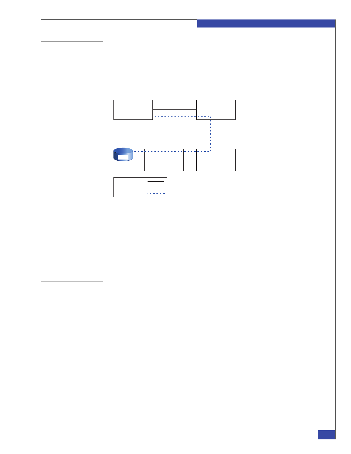
Blade
Array storage
processor or
data director
Fibre Channel
switch
Ethernet
Fibre Channel
NBS
Control
Station
CNS-001862
LUN
Introduction
Understanding the network block service
Figure 1 Network block service
The network block service (NBS) enables the Control Station to access LUNs on an
array. For example, the Control Station uses NBS to read and write its database
information stored in the system (or control) LUNs, and to install NAS software on
the array.
NBS data is sent from the Control Station to a blade over a private LAN connection.
The blade then sends the data to the array over the Fibre Channel connection.
Figure 1 shows the physical path used for the virtual NBS connection.
Configuring dual Control Stations
An NBS client daemon on the Control Station communicates with the NBS server on
the blades.
The Control Station must have at least one blade running normally and accessible
over the local network to run any administrative commands. Administration is not
possible without the NBS connection.
Array management traffic between the Control Station and the array does not use the
NBS service.
A VNX VG2/VG8 gateway optionally has a second Control Station for high
availability. At installation time, CS 0 is the primary CS, and CS 1 is the standby. After
installation, CS 0 is always the active CS. If the primary CS fails, the standby becomes
primary. The former standby remains primary until another failure or reboot.
Therefore, at any time, depending on the circumstances, either CS may become
primary.
Network connections to dual Control Stations can use IP aliasing. This enables the
administrator to contact the primary Control Station with a consistent address,
regardless of which physical Control Station is primary. The Celerra Network Server
System Operations technical module provides details for IP aliasing instructions.
A complete software installation is first performed on CS 0 (CS 1 must be powered
down and its power cable disconnected). When that installation is complete, you
perform the software installation on CS 1. When the installation on the second
Control Station is complete, CS 0 is primary and CS 1 is in standby mode. The
software setup script prompts you about installing the secondary Control Station; it
does not detect this automatically.
How setup works
29
Page 30

EMC CONFIDENTIAL
Introduction
Note: Both Control Stations must be running exactly the same version of the EMCNAS
software. You should verify the software on both Control Stations, even if the first one you
check has the correct version.
Booting blades from the array
Remaining setup steps
Unisphere interface
After the Control Station has installed the NAS software on the array, the blades are
rebooted. This time, the blades boot from system LUN 0 on the array. During this
boot process, the blade BIOS and POST versions are automatically upgraded if
needed.
If Fibre Channel configuration problems exist, you would encounter them now.
Problems such as incorrect zoning, incompatible switch software versions, or
incorrect array initiator records can cause the boot to fail.
The remaining steps set the configuration values, and then create the user volumes.
These steps are typically performed by using the Setup Celerra wizard in the EMC
Unisphere interface. The Setup Celerra wizard walks you through the various
settings—you can perform the same tasks by using the CLI. EMC recommends that
you use the Setup Celerra wizard to prevent accidentally skipping a required setting.
Chapter 10, “Complete Phase 3 Installation,” provides information on the Setup
Wizard.
User tasks that require a user interface are performed by using the EMC Unisphere™
interface. The Unisphere interface replaces the Celerra Manager and Navisphere
Manager interfaces of earlier releases. However, if the backend array is using FLARE
release 29 or earlier, Navisphere Manager is required for some of the backend tasks.
Appendix I provides the procedures to perform these tasks.
VNX gateways and domain support
A domain is a group of EMC storage systems that are centrally administered. A VNX
VG2/VG8 gateway cannot form or join a domain.
30
EMC VNX VG2/VG8 Gateway Configuration Setup Guide
Page 31

Additional information
“Related documentation” on page 13 provides a complete list of other related
documents.
EMC CONFIDENTIAL
Introduction
Additional information
31
Page 32

EMC CONFIDENTIAL
Introduction
32
EMC VNX VG2/VG8 Gateway Configuration Setup Guide
Page 33

EMC CONFIDENTIAL
2
Before Installing
Before you begin installing and setting up the VNX VG2/VG8 gateway, you need to
verify that all components are on site and that site preparation is complete. You also
need to collect configuration information from the customer:
◆ Step 1: Check components ........................................................................................... 34
◆ Step 2: Confirm site preparation................................................................................. 47
◆ Step 3: Collect configuration information.................................................................. 50
Before Installing
33
Page 34

EMC CONFIDENTIAL
Before Installing
Step 1: Check components
VNX VG2/VG8 gateways can come from the factory pre-installed in an EMC cabinet
or as individual enclosures for installation in a customer’s cabinet. The first step is to
check that the components are available for installation:
◆ “Verifying components on site” on page 34
◆ “VG2 components” on page 36
◆ “VG8 components” on page 38
◆ “VG2/VG8 Control Station” on page 39
◆ “VG2/VG8 CPU and power supply/ cooling modules” on page 39
◆ “Identifying blades and I/O modules” on page 40
◆ “Direct- or fabric-connected” on page 45
Ver ify in g components on site
Blade enclosure
components
Verify that all components are on site. Components may already be installed in an
EMC cabinet, or you may need to install them in the customer’s existing 19-inch
NEMA rack. Most required parts are provided with the system, but some are shipped
with particular components and others, like external LAN cables, are provided by the
customer.
Verify that the following items are at the installation site before starting setup. For a
system that was factory-installed in an EMC cabinet, most components are already
mounted in the cabinet.
The VG2 has one blade enclosure. The VG8 has between one and four blade
enclosures. Each blade enclosure includes:
◆ One or more of the following network Host Bus Adaptors (HBAs):
• I/O module with two 10 GbE optical ports
• I/O module with four 1 gigabit Ethernet (GbE) copper ports
• I/O module with two 1 GbE copper ports plus two 1 GbE optical ports
◆ One Fibre HBA in slot 0 of each blade:
• Fibre Channel (FC) I/O module with four 2/4/8 GbE ports
• FC I/O module with four 1/2/4 GbE ports
• Fibre Channel over Ethernet (FCoE) I/O module with two 10 GbE ports
Note: The maximum number of I/O modules in each blade for the VG2 is four; for the VG8, the
maximum is five. The combination of I/O modules must be the same for each blade in a VNX
VG2/VG8 gateway.
34
◆ One or two CPU modules per blade enclosure (for VG8, two CPU modules are
required in enclosure 0 with one or two CPU modules in the remaining
enclosures)
◆ Two management modules per blade enclosure
◆ Two power supply/cooling modules per CPU module
◆ Mounting rails with hardware
◆ Front panel (bezel) with VNX badge
◆ Micro-DB-9 serial cable
EMC VNX VG2/VG8 Gateway Configuration Setup Guide
Page 35

EMC CONFIDENTIAL
CS
CNS-001325
CNS-001639
CS 1 CS Port CS 0 CS Port
Before Installing
Control Station
components
Figure 2 Label for serial modem cable for the CallHome modem
The VG2/VG8 system provides one or two Control Station assemblies. Each
assembly includes:
◆ Control Station
◆ Blank front panel (bezel)
◆ Serial modem cable 10 ft (attached) for the CallHome modem; the label clip
(Figure 2) helps identify this cable.
◆ One 25 ft CAT5 LAN cable (attached) for each Control Station to connect to the
customer’s Ethernet network.
◆ Two 5.5 ft CAT5E LAN cables for each Control Station to connect to the two
management module ports.
◆ One crossover IPMI cable in the Control Station 1 kit (if ordered) to connect the
Control Stations; the label clips (Figure 3) help to identify the cable.
Figure 3 Labels for IPMI cable between Control Stations
Miscellaneous
components
Miscellaneous components may include:
◆ One CallHome modem with power supply cable
◆ Accessory kit, including:
• One crossover LAN cable for connecting your service laptop
• One null-modem serial cable for connecting the service laptop
• One null modem micro-DB-9 to DB9/F serial cable for connecting to the
management module
◆ Accessories including labels and keys
◆ Software kit
◆ Two 16-, 20-, or 32-port Fibre Channel (FC) switches or two 24- or 48-port Fibre
Channel over Ethernet (FCoE) switches (Brocade 8000B or Cisco 5010/5020) with
appropriate cables (optical cables for FC switches; optical or active twinaxial
cables for FCoE switches).
◆ Rail kit including mounting rails and hardware for each component (if system is
not already racked)
Step 1: Check components
35
Page 36

EMC CONFIDENTIAL
AC
AC
DVD
AC
Control Station 0
CPU/power supply filler assembly
CPU module with power supply/
cooling modules
AC
CNS-001640
Before Installing
VG2 components
Figure 4 Example of VNX VG2 system with one blade (rear view)
Figure 4 shows the rear view of an VG2 system that is equipped with one Control
Station and one blade in a single blade enclosure. When only one blade is equipped,
I/O filler panels are required in the unused half of the blade enclosure (as shown) to
meet air flow requirements.
B
MGMT
Serial
console
23
CNS-001642
Control Station 0
MODEM plug
VGA socket
CS
A
1 2301 2301 2301
123
0
0
Blade (Data Mover)
Figure 5 shows the front view of the same VG2 system that is shown in Figure 4. In
this example, a CPU/power supply filler assembly fits into the space where a CPU
module and its associated power supply/cooling modules would go if both blades
were equipped in the enclosure.
Figure 5 Example of VNX VG2 system with one blade (front view)
36
EMC VNX VG2/VG8 Gateway Configuration Setup Guide
Page 37

EMC CONFIDENTIAL
Before Installing
Figure 6 shows the rear view of an VG2 blade enclosure with two blades and two
Control Stations. The right blade in the enclosure has the lower blade number. For
example, in the blade enclosure, blade 2 is on the right and blade 3 is on the left. Each
blade can have from one to four I/O modules (the last slot contains an I/O filler
panel). A mix of different I/O module types is possible.
B
B
MGMT
MGMT
23
Serial
console
Serial
console
12 3012 3
0
Control Station 1
Control Station 0
12 301 2301 2301 23
123
0
0
MODEM plug
VGA socket
MODEM plug
VGA socket
CS
A
CS
A
1 2301
123
0
0
Blade 3
Figure 6 Example of VNX VG2 system—two blades and two CSs (rear)
Figure 7 shows the front view of the same system shown in Figure 6.
DVD
Control Station 1
DVD
Control Station 0
AC
AC
Figure 7 Example of VNX VG2 system—two blades and two CSs (front)
AC
Blade 2
CNS-001641
AC
CNS-001655
Step 1: Check components
37
Page 38

EMC CONFIDENTIAL
Before Installing
VG8 components
Figure 8 shows an VG8 system with two Control Stations, four blade enclosures, and
eight blades (the maximum configuration for this system). In the VG8 system, the
first blade enclosure must have two blades (unlike the VG2 system, which can have
one or two blades). Each blade can have from one to five I/O modules; a mix of
different I/O module types is possible. The specific combination of I/O modules
within a blade must be the same for all blades within the system.
B
23
1
0
23
1
0
B
MGMT
MGMT
23
1
0
23
1
0
Serial
console
Serial
console
12 3012 3
0
12 3012 3
0
Blade 9
123
0
123
0
1 2301
0
1 2301
0
23
23
MODEM plug
VGA socket
MODEM plug
VGA socket
1 2301 23
0
1 2301 23
0
CS
A
CS
A
123
0
123
0
123
0
123
0
1 2301
0
1 2301
0
23
1 2301 23
0
1 2301 23
0
123
0
123
0
23
Blade 2 CNS-001646
Figure 8 Example of VNX VG8 system—eight blades and two CSs (rear)
23
1
0
23
1
0
23
1
0
23
1
0
12 3012 3
0
12 3012 3
0
38
EMC VNX VG2/VG8 Gateway Configuration Setup Guide
Page 39

EMC CONFIDENTIAL
Control Station (front) Power button CNS-000876
CNS-000918
Serial port
Before Installing
VG2/VG8 Control Station
Figure 9 VG2/VG8 Control Station front view
Figure 10 VG2/VG8 Control Station rear view
VG2/VG8 CPU and power supply/ cooling modules
Each VG2/VG8 system can have one or two Control Stations. Figure 9 shows the
front view of the VG2/VG8 Control Station. Note the location of the power button
(also known as the reset button).
Figure 10 shows the rear view of the VG2/VG8 Control Station. Note the location of
the serial console.
The VG2/VG8 blade enclosure can house two blades, and each blade is associated
with a CPU module (viewed from the front of the cabinet). Each blade CPU
(Figure 11) accommodates two power supply/cooling modules, which provide
power and cooling for the I/O modules that are associated with the blade.
Power supplies
1
1
2
Blade CPU
Figure 11 CPU and power supply/cooling modules
Note: The VG2 provides only one blade enclosure, which usually contains two blades; if a
one-blade system is ordered, a CPU filler assembly occupies the location of the blade CPU. See
example in Figure 5 on page 36.
Blade enclosure
1
1
2
2
CNS-001636
Step 1: Check components
39
Page 40

EMC CONFIDENTIAL
CNS-001855
3210
Before Installing
Identifying blades and I/O modules
Fibre Channel I/O
modules
Each blade (also called a Data Mover) in an VG2/VG8 system has one CPU module
and one or more I/O modules to provide backend and frontend connectivity. A
management module provides ports for communication between the Control Stations
and the blades.
A Fibre Channel (FC) I/O module in slot 0 of each blade provides two ports for either
direct-connecting to the back-end storage array or connecting to an FC switch or tape
backup device (Figure 12).
Two versions of this module support fibre speeds of either:
◆ 1, 2, or 4 Gb/s
◆ 2, 4, or 8 Gb/s
The default configuration includes the 2/4/8 Gb/s version of this module.
40
Figure 12 Four-port Fibre Channel I/O module
EMC VNX VG2/VG8 Gateway Configuration Setup Guide
Page 41

EMC CONFIDENTIAL
Before Installing
Fibre Channel over
Ethernet I/O modules
A Fibre Channel over Ethernet (FCoE) I/O module in slot 0 of each blade provides
two ports for connecting to an FCoE switch (Figure 13). The FCoE module is
sometimes referred to as a converged network adaptor (CNA).
Note: FCoE is not supported in a direct-connected system.
The FCoE I/O module supports a fibre speed of up to 10 Gb/s.
10
CNS-001858
Figure 13 Two-port Fibre Channel over Ethernet I/O module
Network I/O modules The following I/O modules are available for network connectivity. The I/O modules
that provide network connectivity are sometimes referred to as host bust adaptors
(HBAs):
◆ Two 10 GbE optical ports (Figure 14).
◆ Four 1 GbE copper 10/100/1000 ports (Figure 15).
◆ Two 1 GbE copper 10/100/1000 ports and two optical 1 GbE ports (Figure 16 on
page 43).
The remaining slots in the blade enclosure can contain a mix of I/O module types,
depending on site requirements. All blades in the VG2/VG8 system must contain the
same combination of I/O modules in the same slots.
Step 1: Check components
41
Page 42

EMC CONFIDENTIAL
10
CNS-001858
Before Installing
Figure 14 Two 10-GbE optical ports
1032
CNS-001854
Figure 15 Four-port 1-GbE copper I/O module
42
EMC VNX VG2/VG8 Gateway Configuration Setup Guide
Page 43

CNS-001856
EMC CONFIDENTIAL
Before Installing
3210
Figure 16 Two 1-GbE copper and two 1-GbE optical ports
SFP modules The gigabit Fibre Channel ports and the optical Gigabit Ethernet ports on some I/O
modules use optical SFP modules (Figure 17). The SFP modules are factory-installed
in the I/O module ports.
SFP
Spring
release
Dust cover
CNS-001857
Figure 17 Optical SFP module
Three types of SFP modules are available. Tab le 3 lists the part numbers for these
modules.
Table 3 SFP module types
SFP module type SFP module part number
SFP transceiver multimode for 1-, 2-, or 4-GbE ports 019-078-032
SFP+ transceiver limiting multimode for 10-GbE ports 019-078-041
SFP+ transceiver multimode for 2-, 4-, or 8-GbE ports 019-078-042
Step 1: Check components
43
Page 44

EMC CONFIDENTIAL
Serial
console
MGMT
CS
B
MODEM plug
VGA socket
A
0
123
0
123
0
12 301 2301 2301 23
0
1 2301
23
0
12 3012 3
Serial
console
MGMT
CS
B
MODEM plug
VGA socket
A
Control Station 1
Management
module B
Control Station 0
CNS-001656
Management
module A
2
0
1
#
Port 2
Port 0
RS-232 serial port
7-segment display
(blade enclosure ID)
CNS-001647
Port 1
Before Installing
Management module Each blade enclosure has two management modules. The two modules are redundant
for each enclosure. Figure 18 shows the rear view of a blade enclosure with
management modules A and B.
Figure 18 Management modules in a blade enclosure
The management module has three RJ-45 Ethernet ports (private LAN), one DB-9
(RS-232 serial port) connector, various LEDs, and a seven-segment display showing
the blade enclosure ID (Figure 19).
44
Figure 19 Management module
EMC VNX VG2/VG8 Gateway Configuration Setup Guide
Page 45

EMC CONFIDENTIAL
!!
!
!!
2130
12 30
1
0
1
0
Before Installing
Direct- or fabric-connected
Direct-connected
system
The setup procedures for the VG2/VG8 provide steps for direct-connected or
fabric-connected systems. The VG2 can be direct- or fabric-connected; the VG8 is
usually fabric-connected, but direct-connected VG8 systems are also supported.
Your customer may have ordered a VNX or Symmetrix array with the VNX gateway,
or your customer may already have the array. If your customer ordered the optional
cabinet, the components are installed in the cabinet at the EMC factory.
The installation of the array is outside the scope of this guide. Refer to the VNX or
Symmetrix installation documentation.
A working system requires a fully operational VNX array (for example, the
VNX5300) and a cabinet.
Figure 20 shows an example of a VNX VG2 gateway (two blades and one Control
Station) with a CX4-120 storage array. Because components can have different depths,
you should stack them within the cabinet to facilitate easy access to the rear.
Note: FCoE is not supported in a direct-connected system.
Disk-array enclosure
Standby power supply
CX4-120 storage
processor
12 30
Control Station
Blade enclosure
123
0
12 301
0
23
23
1
0
Figure 20 Example of VNX VG2 gateway with CX4-120 storage array
123
0
12 30
23
12 301
0
12 3
0
CNS-001658
Step 1: Check components
45
Page 46

EMC CONFIDENTIAL
Before Installing
Fabric-connected
system
A working system requires one to four supported and fully operational Symmetrix or
VNX arrays and a cabinet.
Figure 21 shows the components of a VNX VG2/VG8 system. It also shows the LAN
connections between VNX gateway components and the Fibre Channel (FC)
connections to the FC or FCoE switches that in turn connect to the Symmetrix or VNX
arrays.
Control Station
Blade
Fibre
channel
switch A
Fibre
channel
switch B
(optional)
Boot array
Additional
array
(optional)
Additional
array
(optional)
CIP-000620
Figure 21 Components of a VNX fabric-connected gateway system
Your customer may have ordered a Symmetrix or VNX array with the VNX gateway,
or your customer may already have one or more arrays installed.
The installation of arrays is outside the scope of this guide. Refer to the appropriate
Symmetrix or VNX installation documentation as needed.
46
EMC VNX VG2/VG8 Gateway Configuration Setup Guide
Page 47

Step 2: Confirm site preparation
The following site preparation must be completed by the customer before you can
install and set up a VNX VG2/VG8 gateway. Some steps differ depending on
whether the system was installed in a cabinet at the factory or will be installed in the
customer’s cabinet on site.
EMC CONFIDENTIAL
Before Installing
EMC factory-installed cabinet
Customer’s cabinet
If the VNX gateway was factory-installed in an EMC cabinet, confirm the following:
◆ Electrical wiring to accommodate the cabinet’s power cables is in place at the
facility.
◆ EMC cabinets include four 240-volt AC power cables. To support all
high-availability features, EMC recommends that you connect the power cables to
two different circuits.
If the network server is being installed in the customer’s existing cabinet:
◆ Verify that the customer’s cabinet is a standard 19-inch NEMA cabinet, such as an
EMC cabinet.
Verify that the customer ’s cabinet has sufficient space for the network server.
Vertical rack space is measured in units called “U.” One U equals 1.75 inches (4.45
centimeters). A maximum VNX VG2 gateway requires 4U of vertical space; a
maximum VG8 gateway requires 10U of vertical space.
◆ Verify that the cabinet is deep enough to accommodate the components (at least
31 inches/79 centimeters). Verify the supplied rail kits fit the spacing between the
front and rear channels in the cabinet.
◆ Verify that the customer’s cabinet has sufficient power for the network server. The
following values should be balanced between the four circuits. Each circuit
should be able to carry the full load in case another circuit fails:
• Maximum VG2 configuration (two blades and two Control Stations) requires
790 V Amp
• Maximum VG8 configuration (eight blades and two Control Stations) requires
2360 V Amp
◆ Verify that the facility has adequate network connections for required subnets.
Each blade requires separate network connections.
Celerra Tools on Powerlink provides more information on space and power
requirements.
All systems
For all systems:
◆ Verify that the array being used as the boot array is already installed and
configured. If you are installing a new array with the VNX gateway, complete the
array installation first.
◆ Verify that there are at least two available ports on the FC or FCoE switch for each
blade. Check the EMC E-Lab Interoperability Navigator on Powerlink to verify
that the switch is supported for the VNX gateway you are installing. This is not
applicable for direct-connected VNX gateways.
Step 2: Confirm site preparation
47
Page 48

EMC CONFIDENTIAL
Before Installing
◆ Verify the switch or switches have available ports to connect to the array. The
FC/FCoE connections between a Symmetrix array and a switch used for the VNX
gateway cannot be used for any other host computer. VNX arrays can share the
connection between the switch and the array with other hosts. This is not
applicable for direct-connected VNX gateway.
◆ Verify that the facility has adequate network connections for required subnets.
Each blade requires separate network connections:
• “Step 6: External network cables” on page 76 provides information for the
cable and connector requirements for a fabric-connected VG2 system.
• “Step 5: External network cables” on page 87 provides information for the
cable and connector requirements for a direct-connected VG2 system.
• “Step 6: External network cables” on page 110 provides information for the
cable and connector requirements for a fabric-connected VG8 system.
• “Step 5: External network cables” on page 123 provides information for the
cable and connector requirements for a direct-connected VG2 system.
◆ Verify that the supplied cables have the correct connectors for the customer’s
FC/FCoE switches (optical cables for FC switches; optical or active twinaxial
cables for FCoE switches). This is not applicable for direct-connected VNX
gateways.
Systems with Symmetrix arrays
Fabric-connected systems with VNX arrays
If you are connecting the VNX VG2/VG8 gateway to a Symmetrix array (DMX,
VMAX, or VMAXe):
◆ Check the EMC E-Lab Interoperability Navigator on Powerlink to verify that the
array is supported and the required array software versions are installed.
◆ Verify that each of two different channel directors has at least one Fibre Channel
port (two ports total) for the exclusive use of the VNX VG2/VG8 gateway.
Verify that EMC has configured the Symmetrix array with the required
hypervolumes for the VNX gateway volumes and user volumes. For more
information, see:
http://www.cs.isus.emc.com/config/Products/
EMCProducts/Celerra/Celerra.htm
◆ You must manually zone the FC switch if you are using a Symmetrix array for the
boot array. Appendix F, “Manually Zone Switches and Configure System LUNs,”
provides information about manually zoning the FC switch.
If you are connecting the VNX gateway to a fabric-connected VNX array:
◆ Check the EMC E-Lab Interoperability Navigator on Powerlink to verify that the
array is a supported model. Verify that the required array software versions are
installed.
◆ Verify that all SAN ports on the array are connected to the Fibre Channel switch
or switches. If some SAN ports are not in use, verify that there are available
switch ports to connect them.
48
◆ Verify that there are at least four unused disks available in the array (these are the
vault disks). The array must also have an available hot spare disk or another
unused disk that can be configured as a hot spare.
◆ Verify that both SPs are up and functioning, that write cache is enabled, and that
existing LUNs are not trespassed or faulted.
EMC VNX VG2/VG8 Gateway Configuration Setup Guide
Page 49

EMC CONFIDENTIAL
Before Installing
Direct-connected systems with VNX arrays
Access Logix
If you are connecting the VNX gateway to a direct-connected VNX array:
◆ Verify that the array being used is already installed and configured. If you are
installing a new array with the VNX gateway, complete the array installation first.
◆ Check the EMC E-Lab Interoperability Navigator on Powerlink to verify that the
array is a supported model. Verify that the required array software versions are
installed.
◆ Verify that one or two SAN ports on each array SP are available to connect to the
blades.
◆ Verify that there are at least four unused disks available in the array (these are the
vault disks). The array must also have an available hot spare disk or another
unused disk that can be configured as a hot spare.
◆ Verify that both SPs are up and functioning, that write cache is enabled, and that
existing LUNs are not failed over.
EMC Access Logix™ is a licensed software option for a VNX array. If the customer
does not already have Access Logix enabled for an existing array, a license may have
been ordered with the VNX gateway system. If Access Logix is not enabled and a
license was not included in the order, contact the EMC Software Refresh group to
determine entitlement prior to enabling Access Logix.
Step 2: Confirm site preparation
49
Page 50

EMC CONFIDENTIAL
Before Installing
Step 3: Collect configuration information
When you set up a VNX gateway, you must enter configuration information. Collect
all required information before beginning setup.
Use the worksheets in Appendix H, “Setup Worksheets,” to collect and record
configuration information. Leave the completed worksheets with the customer as a
record of how the system is configured.
Some of the configuration information may have already been provided as part of the
CCA process. Verify these values with the customer as well.
Some setup steps are optional, depending on which service offering the customer
purchased. For example, the number of shares and exports you create varies with
different service offerings.
50
EMC VNX VG2/VG8 Gateway Configuration Setup Guide
Page 51

EMC CONFIDENTIAL
PART 2
Phase 2 Installation
This phase of the setup includes physically installing the system, cabling it to the
customer’s network, and configuring the Control Station and ConnectHome. This
phase is complete when the system successfully calls home and you have filled out
the hand-off worksheet. The steps to complete this phase are included in the
following chapters:
Chapter 3, “Install Components in Customer’s Cabinet”
This chapter explains how to install the system in a customer’s cabinet for systems
that are not shipped in an EMC cabinet.
Chapter 4, “Connect Cables for a Fabric-connected VG2”
This chapter explains how to cable a fabric-connected VG2 gateway.
Chapter 5, “Connect Cables for a Direct-connected VG2”
This chapter explains how to cable a direct-connected VG2 gateway.
Chapter 6, “Connect Cables for a Fabric-connected VG8”
This chapter explains how to cable a fabric-connected VG8 gateway.
Chapter 7, “Connect Cables for a Direct-connected VG8”
This chapter explains how to cable a direct-connected VG8 gateway.
Chapter 8, “Configure the boot array”
This chapter explains how to configure a VNX array being used as the boot array.
Chapter 9, “Install and Configure EMC NAS Software”
This chapter explains how to install and configure the EMC NAS software on the
Control Station and blades. It also explains how to complete boot array configuration.
Page 52

EMC CONFIDENTIAL
Page 53

EMC CONFIDENTIAL
3
Install Components
in Customer’s
Cabinet
If the VNX VG2/VG8 gateway was not installed in an EMC cabinet at the factory, you
need to install the components in the customer’s cabinet on site. Some cables must be
connected before installing the Control Stations:
◆ Installing components .................................................................................................. 54
◆ Component layout ........................................................................................................ 55
◆ System cabling............................................................................................................... 56
Install Components in Customer’s Cabinet
53
Page 54

EMC CONFIDENTIAL
WARNING
Install Components in Customer’s Cabinet
Installing components
If the VNX VG2/VG8 gateway was installed in an EMC cabinet at the factory, skip
this step.
Using the rails and other hardware included with the network server, install the
components into the customer’s cabinet or rack. Before proceeding, verify that the
customer’s cabinet has enough space and power available. Chapter 2, “Before
Installing,” provides more information.
The specific mounting instructions depend on the type of cabinet or rack and the type
of rail kit. For 19-inch NEMA cabinets, there are two different types of mounting rails:
◆ If the mounting rails have alignment pins (new-style rails) (Figure 22), the EMC
◆ If the mounting rails do not have alignment pins and come with clip nuts
Rails and Enclosures (CX3-Series Storage Systems) Field Installation Guide or EMC
Rails and Enclosures (CX4-Series Storage Systems) Field Installation Guide provides
mounting instructions.
(old-style rails), also shown in Figure 22, the EMC Rails and Enclosures (CX3-Series
Storage Systems) Field Installation Guide or EMC Rails and Enclosures (CX4-Series
Storage Systems) Field Installation Guide provides mounting instructions.
New-Style Rails
Right Rear
Mounting Rail
Screw (2)
Alignment
Pin
Clip Nut
(2)
Right Rear
Screw (2)
Alignment
Pin (2)
Mounting Rail
Clip Nut
(2)
Old-Style Rail
CIP-000233
54
Figure 22 Old- and new-style 19-inch NEMA rails
Pay attention to the warnings in the installation guides, including the warnings
about lifting the enclosures.
EMC VNX VG2/VG8 Gateway Configuration Setup Guide
Page 55

Component layout
Table 4 Component information
EMC CONFIDENTIAL
Install Components in Customer’s Cabinet
Begin with the lowest component in the cabinet and work towards the top. The VNX
gateway, FC/FCoE switches, and arrays do not have to be in the same cabinet.
If you are installing a new Symmetrix or VNX array at the same time, refer to the
appropriate installation documentation for the array.
The relative position of the components within the rack is not critical as long as:
◆ Cables can reach connecting ports or receptacles
◆ Access to connections at the rear of the cabinet is possible
Note: Enclosures have different depths. You should stack enclosures within the cabinet to
facilitate access to the rear of the components.
Ta bl e 4 provides information about the VG2/VG8 components and examples of
stacking these components.
Component Reference
Blade A blade includes the I/O modules that you access from the rear of the
cabinet and an associated CPU module with power supply/cooling
modules that you access from the front of the cabinet.
I/O modules • “Fibre Channel I/O modules” on page 40
• “Network I/O modules” on page 41
CPU module with
power supply/
cooling modules
Management
module
Control Station “Control Station components” on page 35
VG2 examples • Figure 4 on page 36
VG8 example Figure 8 on page 38
“VG2/VG8 CPU and power supply/ cooling modules” on page 39
“Management module” on page 44
• Figure 5 on page 36
• Figure 6 on page 37
• Figure 7 on page 37
• Figure 20 on page 45
When the system first boots, the Control Station assigns the blade identifiers based on
the management module ports to which the blades are connected. The blades then
store their identities in the memory of the blade enclosure.
Component layout
55
Page 56

EMC CONFIDENTIAL
Install Components in Customer’s Cabinet
System cabling
This guide covers four gateway configurations. Each configuration has a separate
chapter for cabling instructions:
◆ Go to Chapter 4, “Connect Cables for a Fabric-connected VG2,” to cable a
◆ Go to Chapter 5, “Connect Cables for a Direct-connected VG2,” to cable a
◆ Go to Chapter 6, “Connect Cables for a Fabric-connected VG8,” to cable a
◆ Go to Chapter 7, “Connect Cables for a Direct-connected VG8,” to cable a
fabric-connected VG2 system.
direct-connected VG2 system.
fabric-connected VG8 system.
fabric-connected VG8 system.
56
EMC VNX VG2/VG8 Gateway Configuration Setup Guide
Page 57

EMC CONFIDENTIAL
4
Connect Cables for a
Fabric-connected
VG2
The next step is to connect the cables from the VNX VG2 gateway to the storage
array(s), and to connect the customer’s network and power cables.
Connect all cables in the order shown. Do not connect the blade enclosure power
cables until directed to do so in the software installation chapter.
Arrange the cables so that a failed component can be removed without disconnecting
cables on other components:
◆ Step 1: Blade Fibre Channel cables ............................................................................. 58
◆ Step 2: Array Fibre Channel cables............................................................................. 60
◆ Step 3: Serial cables ....................................................................................................... 72
◆ Step 4: Optional tape backup device cables .............................................................. 73
◆ Step 5: Private LAN cables........................................................................................... 74
◆ Step 6: External network cables................................................................................... 76
Connect Cables for a Fabric-connected VG2
57
Page 58

EMC CONFIDENTIAL
IMPORTANT
!
Connect Cables for a Fabric-connected VG2
Step 1: Blade Fibre Channel cables
The figures in this section of the document contain logical drawings of cable
connections. To view the physical port locations, see “Identifying blades and I/O
modules” on page 40.
Fibre Channel cables connect the I/O modules in the blades to the Symmetrix and
VNX arrays through FC/FCoE switches. Each blade has two Fibre Channel ports that
must be connected to both storage processors of the VNX array.
The Fibre Channel cables have not been connected.
Different switches use different cable connectors. The supplied optical cables always
have LC connectors on both ends. If the customer’s switch needs different connectors,
additional cables may have been ordered.
The cabling and zoning rules for a VNX gateway system are minimum requirements.
You can have additional paths between the array and the blades, but you must
observe the following blade limits:
◆ 16 paths per LUN for Symmetrix storage arrays
◆ 8 paths per LUN for VNX storage arrays
◆ 4 paths per LUN is recommended for most configurations
Use the “FC/FCoE cabling worksheet” on page 273 to record the ports you actually
cable.
Arrange the cables so that a failed component can be removed without disconnecting
other cables.
Use small form-factor pluggable (SFP) modules in the SP and I/O module ports to
connect the Fibre Channel cables (see “SFP modules” on page 43).
The Fibre Channel connections from the blades to the switch or switches are always
the same, regardless of the array to which you are connecting. Two switches are
recommended for highest availability.
If you are using:
◆ Two switches, connect the cables as shown in Figure 23 on page 59.
◆ One switch, connect the cables as shown in Figure 24 on page 59.
The four-port Fibre Channel I/O module is available in two versions:
◆ 4 Gb/s supporting fibre speeds of 1, 2, or 4 Gb/s
◆ 8 Gb/s supporting fibre speeds of 2, 4, or 8 Gb/s
The two-port FCoE I/O module supports fibre speeds of up to 10 Gb/s.
Verify that the switch ports are configured for auto-negotiation (see switch
documentation for steps to configure auto-negotiation). The FC/FCoE ports
automatically adjust to the appropriate rate, depending on the rate of the attached
client.
If the blades fail to boot from the array, you may have to manually force the Fibre
Channel speed setting. If you must do this, set the switch ports to the highest speed
(1, 2, 4, or 8 Gb/s) that the switch can support. Appendix D, “Resolve Blade Boot
Failures,” provides more information.
58
EMC VNX VG2/VG8 Gateway Configuration Setup Guide
Page 59

EMC CONFIDENTIAL
1
3
4
2
Blade 3
Blade 2
SFP
SFP
SFP
SFP
CNS-001853
Port 0
Port 1
Port 0
Port 1
Fibre
channel
switch
B
Fibre
channel
switch
A
Connect Cables for a Fabric-connected VG2
Figure 23 Blades connected to two switches for high availability
Record the switch ports you connect on the “FC/FCoE cabling worksheet” on
page 273.
SFP
Blade 3
Port 0
Port 1
SFP
Port 0
SFP
Blade 2
Port 1
SFP
Figure 24 Blades connected to a single switch
Note: Label each end of the FC cable with the blade number, I/O module slot number, port
name, FC switch port number, and FC switch number, before you connect the cable.
4
3
Fibre
channel
switch
2
1
CNS-001850
Step 1: Blade Fibre Channel cables
59
Page 60

EMC CONFIDENTIAL
CIP-000412
Switch A
Switch B
Channel Directors
1
2
Connect Cables for a Fabric-connected VG2
Step 2: Array Fibre Channel cables
If the Symmetrix or VNX array is not already connected, connect the array to the
Fibre Channel switch or switches. The following sections show how to cable the array
to the switches. The Fibre Channel cables for this step are not included with the VNX
gateway.
Connecting a Symmetrix array
For a Symmetrix array (DMX, VMAX, or VMAXe), you need two channel director
ports dedicated to the VNX gateway system. These ports must be on different
channel directors as shown in the examples in Figure 25 or Figure 26 on page 61.
Note: You must manually zone the FC switch if you are using a Symmetrix array for the boot
array. Appendix F, “Manually Zone Switches and Configure System LUNs,” provides
information about manually zoning the switch.
60
EMC VNX VG2/VG8 Gateway Configuration Setup Guide
Figure 25 Example of Symmetrix channel directors connected to two switches
Note: The Symmetrix DMX, VMAX, and VMAXe directors may have different numbers of
ports than shown in Figure 25.
To make connections to two switches for high availability as illustrated in the
example in Figure 25:
1. Verify from the CCA activity or the Symmetrix administrator the channel director
ports to use for the VNX gateway system.
2. Connect the specified channel director port to the first switch.
3. Connect the specified port on another channel director to the second switch.
4. Record the channel director ports you connected to the switch ports by using the
“FC/FCoE cabling worksheet” on page 273.
Page 61

Switch Channel Directors
1
2
EMC CONFIDENTIAL
Connect Cables for a Fabric-connected VG2
CIP-000411
Figure 26 Example of Symmetrix DMX channel directors connected to a single switch
Note: The Symmetrix VMAX and VMAXe channel directors have fewer ports than shown in
Figure 26.
To make connections to one switch as illustrated in the example in Figure 26:
1. Verify from the CCA activity or the Symmetrix administrator the channel director
ports to use for the VNX gateway system.
2. Connect one specified channel director port to the switch.
3. Connect the specified port on another channel director to the switch.
4. Record the channel director ports you connected to the switch ports by using the
“FC/FCoE cabling worksheet” on page 273.
Step 2: Array Fibre Channel cables
61
Page 62

EMC CONFIDENTIAL
SP B
SP A
23
23
Switch ASwitch B
CNS-000894
1
2
3
4
Connect Cables for a Fabric-connected VG2
Connecting a VNX7500 array
Figure 27 VNX7500 connected to two switches for high availability (example)
The VNX7500 SP has from 4 to 14 ports to connect to SAN fabrics. If all of the SAN
ports on the array are already connected to the fabric, you need not change these
connections. If the array has two available ports on each SP, the recommended
practice is to cable these ports to the switches and dedicate them to the VNX gateway
system.
If you are using two switches to connect a VNX7500 array, connect the cables as
shown in the example in Figure 27.
The array SAN ports 2 and 3 are used in this example, but you can use any two
available ports on each SP:
1. Connect SP A slot 0, port 2 to switch A.
2. Connect SP B slot 0, port 2 to switch A.
3. Connect SP A slot 0, port 3 to switch B.
4. Connect SP B slot 0, port 3 to switch B.
5. Record the SP ports you connected to the switch ports by using the “FC/FCoE
cabling worksheet” on page 273.
62
EMC VNX VG2/VG8 Gateway Configuration Setup Guide
Page 63

EMC CONFIDENTIAL
Connect Cables for a Fabric-connected VG2
If you are using one switch to connect a VNX7500 array, connect the cables as shown
in the example in Figure 28.
23
23
SP B
4
2
SP A
3
1
Switch
CNS-000895
Figure 28 VNX7500 connected to a single switch (example)
The array SAN ports 2 and 3 are used in this example, but you can use any two ports
on each SP:
1. Connect SP A slot 0, port 2 to the switch.
2. Connect SP B slot 0, port 2 to the switch.
3. Connect SP A slot 0, port 3 to the switch.
4. Connect SP B slot 0, port 3 to the switch.
5. Record the SP ports you connected to the switch ports by using the “FC/FCoE
cabling worksheet” on page 273.
Step 2: Array Fibre Channel cables
63
Page 64

EMC CONFIDENTIAL
0
SP B SP A
1
2
3
0
1
2
3
4
3
Switch ASwitch B
2
1
CNS-000892
Connect Cables for a Fabric-connected VG2
Connecting a VNX5700 array
Figure 29 VNX5700 connected to two switches for high availability (example)
The VNX5700 SP has from two to eight ports to connect to SAN fabrics. If all of the
SAN ports on the array are already connected to the fabric, you need not change these
connections. If the array has two available ports on each SP, the recommended
practice is to cable these ports to the switches and dedicate them to the VNX gateway
system.
If you are using two switches to connect a VNX5700 array, connect the cables as
shown in the example in Figure 29.
The array SAN ports 2 and 3 are used in this example, but you can use any two ports
on each SP:
1. Connect SP A slot 0, port 2 to switch A.
2. Connect SP B slot 0, port 2 to switch A.
3. Connect SP A slot 0, port 3 to switch B.
4. Connect SP B slot 0, port 3 to switch B.
5. Record the SP ports you connected to the switch ports by using the “FC/FCoE
cabling worksheet” on page 273.
64
EMC VNX VG2/VG8 Gateway Configuration Setup Guide
Page 65

If you are using one switch to connect aVNX5700 array, connect the cables as shown
SP B SP A
4
Switch
2
1
3
CNS-000892
0
1
2
3
0
1
2
3
in the example in Figure 30.
Figure 30 VNX5700 connected to a single switch (example)
The array SAN ports 2 and 3 are used in this example, but you can use any two ports
on each SP:
1. Connect SP A slot 0, port 2 to the switch.
EMC CONFIDENTIAL
Connect Cables for a Fabric-connected VG2
2. Connect SP B slot 0, port 2 to the switch.
3. Connect SP A slot 0, port 3 to the switch.
4. Connect SP B slot 0, port 3 to the switch.
5. Record the SP ports you connected to the switch ports by using the “FC/FCoE
cabling worksheet” on page 273.
Step 2: Array Fibre Channel cables
65
Page 66

EMC CONFIDENTIAL
Connect Cables for a Fabric-connected VG2
Connecting a VNX5500 array
Figure 31 VNX5500 connected to two switches for high availability (example)
The VNX5500 SP has from one to seven ports to connect to SAN fabrics. If all of the
SAN ports on the array are already connected to the fabric, you need not change these
connections. If the array has two available ports on each SP, the recommended
practice is to cable these ports to the switches and dedicate them to the VNX gateway
system.
If you are using two switches to connect a VNX5500 array, connect the cables as
shown in the example in Figure 31.
Switch ASwitch B
SP B SP A
4
3
2
1
0
2
3
2
1
0
1
3
CNS-000892
The array SAN ports 2 and 3 are used in this example, but you can use any two ports
on each SP:
1. Connect SP A slot 0, port 2 to switch A.
2. Connect SP B slot 0, port 2 to switch A.
3. Connect SP A slot 0, port 3 to switch B.
4. Connect SP B slot 0, port 3 to switch B.
5. Record the SP ports you connected to the ports using the “FC/FCoE cabling
worksheet” on page 273.
66
EMC VNX VG2/VG8 Gateway Configuration Setup Guide
Page 67

If you are using one switch to connect a VNX5500 array, connect the cables as shown
SP B SP A
4
Switch
2
1
3
CNS-000892
0
1
2
3
0
1
2
3
in the example in Figure 32.
Figure 32 VNX5500 connected to a single switch (example)
The array SAN ports 2 and 3 are used in this example, but you can use any two ports
on each SP:
1. Connect SP A slot 0, port 2 to the switch.
EMC CONFIDENTIAL
Connect Cables for a Fabric-connected VG2
2. Connect SP B slot 0, port 2 to the switch.
3. Connect SP A slot 0, port 3 to the switch.
4. Connect SP B slot 0, port 3 to the switch.
5. Record the SP ports you connected to the switch ports by using the “FC/FCoE
cabling worksheet” on page 273.
Step 2: Array Fibre Channel cables
67
Page 68

EMC CONFIDENTIAL
Connect Cables for a Fabric-connected VG2
Connecting a VNX5300 array
Figure 33 VNX5300 connected to two switches for high availability (example)
The VNX5300 SP has two to four ports to connect to SAN fabrics. If all of the SAN
ports on the array are already connected to the fabric, you need not change these
connections. If the array has two available ports on each SP, the recommended
practice is to cable these ports to the switches and dedicate them to the VNX gateway
system.
If you are using two switches to connect a VNX5300 array, connect the cables as
shown in the example in Figure 33.
Switch ASwitch B
SP B SP A
4
3
2
1
0
2
3
2
1
0
1
3
CNS-000892
The array SAN ports 2 and 3 are used in this example, but you can use any two ports
on each SP:
1. Connect SP A slot 0, port 2 to switch A.
2. Connect SP B slot 0, port 2 to switch A.
3. Connect SP A slot 0, port 3 to switch B.
4. Connect SP B slot 0, port 3 to switch B.
5. Record the SP ports you connected to the switch ports by using the “FC/FCoE
cabling worksheet” on page 273.
68
EMC VNX VG2/VG8 Gateway Configuration Setup Guide
Page 69

If you are using one switch to connect a VNX5300 array, connect the cables as shown
in the example in Figure 34.
Switch
SP B SP A
3
2
1
0
2
3
2
1
0
3
1
4
Figure 34 VNX5300 connected to a single switch (example)
The array SAN ports 2 and 3 are used in this example, but you can use any two ports
on each SP:
1. Connect SP A slot 0, port 2 to the switch.
EMC CONFIDENTIAL
Connect Cables for a Fabric-connected VG2
CNS-000892
2. Connect SP B slot 0, port 2 to the switch.
3. Connect SP A slot 0, port 3 to the switch.
4. Connect SP B slot 0, port 3 to the switch.
5. Record the SP ports you connected to the switch ports by using the “FC/FCoE
cabling worksheet” on page 273.
Appendix G, “Cable Connections from Fibre Channel Switch to Storage Array,”
provides information on cabling legacy CLARiiON arrays.
Step 2: Array Fibre Channel cables
69
Page 70

EMC CONFIDENTIAL
Connect Cables for a Fabric-connected VG2
Connecting a VNX5100 array
Figure 35 VNX5100 connected to two switches for high availability (example)
If all of the SAN ports on the array are already connected to the fabric, you need not
change these connections. If the array has two available ports on each SP, the
recommended practice is to cable these ports to the switches and dedicate them to the
VNX gateway system.
If you are using two switches to connect a VNX5100 array, connect the cables as
shown in the example in Figure 33.
Switch ASwitch B
SP B SP A
4
3
2
1
0
2
3
2
1
0
1
3
CNS-000892
The array SAN ports 2 and 3 are used in this example, but you can use any two ports
on each SP:
1. Connect SP A slot 0, port 2 to switch A.
2. Connect SP B slot 0, port 2 to switch A.
3. Connect SP A slot 0, port 3 to switch B.
4. Connect SP B slot 0, port 3 to switch B.
5. Record the SP ports you connected to the switch ports by using the “FC/FCoE
cabling worksheet” on page 273.
70
EMC VNX VG2/VG8 Gateway Configuration Setup Guide
Page 71

If you are using one switch to connect a VNX5100 array, connect the cables as shown
in the example in Figure 34.
Switch
SP B SP A
3
2
1
0
2
Figure 36 VNX5100 connected to a single switch (example)
3
2
1
0
3
1
4
The array SAN ports 2 and 3 are used in this example, but you can use any two ports
on each SP:
1. Connect SP A slot 0, port 2 to the switch.
EMC CONFIDENTIAL
Connect Cables for a Fabric-connected VG2
CNS-000892
Connecting additional arrays
2. Connect SP B slot 0, port 2 to the switch.
3. Connect SP A slot 0, port 3 to the switch.
4. Connect SP B slot 0, port 3 to the switch.
5. Record the SP ports you connected to the switch ports by using the “FC/FCoE
cabling worksheet” on page 273.
Appendix G, “Cable Connections from Fibre Channel Switch to Storage Array,”
provides information on cabling legacy CLARiiON arrays.
If you are connecting multiple arrays to the VNX gateway system, connect the
additional arrays to the Fibre Channel switch after the installation of the EMC NAS
software. Connect the Fibre Channel cables for the additional arrays as shown in the
preceding sections. Chapter 10, “Complete Phase 3 Installation,” provides detailed
instructions.
Step 2: Array Fibre Channel cables
71
Page 72

EMC CONFIDENTIAL
Connect Cables for a Fabric-connected VG2
Step 3: Serial cables
Serial cables connect the Control Station to the CallHome modem.
To connect the serial cables:
1. Refer to Figure 38 and connect the modem serial cable (labeled CS telephone icon)
from the CS 0 serial port to the first external modem.
2. Then connect the modem to an analog telephone line supplied by the customer.
The label clip on the modem serial cable is shown in Figure 37.
Figure 37 Label for serial modem cable for the CallHome modem
Modem
Control Station
Figure 38 Serial connection from Control Station to modem
3. For dual Control Station systems, connect the modem serial cable (labeled CS
telephone icon) from the CS 1 serial port to the second external modem. Then,
connect the modem to an analog telephone line supplied by the customer.
CIP-001139
72
EMC VNX VG2/VG8 Gateway Configuration Setup Guide
Page 73

Step 4: Optional tape backup device cables
"LADE
0ORT
#.3MO
"LADE
0ORT
0ORT
0ORT
&#INBOOT
SLOT
&#INBOOT
SLOT
"LADE "LADE
&#O%INBOOT
SLOT
&#O%INBOOT
SLOT
&#&#
The VNX gateway can connect to tape backup devices by using optical cables, either
directly or through an FC/FCoE switch.
If you have an FC I/O module in the boot slot, use ports 2 and 3 to connect a tape
device (Figure 39). If you have an FCoE I/O module in the boot slot, connect the tape
device to any two ports of an FC I/O module in a different slot (Figure 40).
The ports sense the:
◆ Speed of the device they connect to and automatically adjust to the appropriate
speed (depending on the type of I/O module installed).
◆ Topology of the Fibre Channel network they are connected to and automatically
configure for arbitrated loop or switched fabric as needed.
To connect the FC I/O module:
1. Connect one end of the appropriate cable to the FC I/O module in blade 2 (see
examples in Figure 39 and Figure 40).
EMC CONFIDENTIAL
Connect Cables for a Fabric-connected VG2
Figure 39 Tape device ports on FC (example 1)
Figure 40 Tape device ports on FC (example 2)
2. Connect the other end of the cable to an FC/FCoE switch, or directly to a tape
device.
3. Optionally, connect the remaining port to a switch or tape device.
4. Repeat steps 1 through 3 for the other blade as needed.
Step 4: Optional tape backup device cables
73
Page 74

EMC CONFIDENTIAL
CAUTION
!
0
123
0
123
0
12 3
0
1 2301 2301 23
0
1 2301
23
0
12 3
0
12 3
Management
module B
CNS-001679
Management
module A
Port 1
Port 0
Port 2
Connect Cables for a Fabric-connected VG2
Step 5: Private LAN cables
The private (internal) LAN cables connect the Control Station to the blades through
the blade enclosure’s management modules. These cables and switches make up a
private network that does not connect to any external network.
The blade enclosure has two management modules, which are redundant. If module
A fails, module B assumes control of the private network. The Control Stations
communicate to the blades through the management modules.
Figure 41 shows VG2 management module with the private LAN ports 0, 1, and 2.
74
Figure 41 VG2 management modules
Do not connect any other cables to the management modules, such as public LAN
cables, or array management port cables.
To connect the private LAN cables:
1. Connect an RJ-45 Ethernet cable from port 1 on management module A to the
port labeled A on CS 0 (cable 1 in Figure 42).
2. Connect an RJ-45 Ethernet cable from port 1 on management module B to the port
labeled B on CS 0 (cable 2 in Figure 42).
3. For dual Control Station systems, connect an RJ-45 Ethernet cable from port 2 on
management module A to the port labeled A on CS 1 (cable 3 in Figure 42).
4. For dual Control Station systems, connect an RJ-45 Ethernet cable from port 2 on
management module B to the port labeled B on CS 1 (cable 4 in Figure 42).
EMC VNX VG2/VG8 Gateway Configuration Setup Guide
Page 75

Control Station 1
Control Station 0
123
0
12 3
0
MODEM plug
4
1 2301 2301 23
0
VGA socket
MODEM plug
VGA socket
2
3
EMC CONFIDENTIAL
Connect Cables for a Fabric-connected VG2
B
B
MGMT
MGMT
23
12 3
0
Serial
console
Serial
console
12 3
0
CS
A
CS
A
1
123
0
1 2301
0
Management
module B
Management
module A
Figure 42 Private LAN cables to Control Station (two-blade system)
5. For dual Control Station systems, connect a crossover (IPMI) cable from the port
labeled CS on CS 0 to the port labeled CS on CS 1 (see Figure 43).
Control
Station
1
Control
Station
0
Figure 43 IPMI Crossover cable between CS 0 and CS 1
MODEM plug
VGA socket
MODEM plug
VGA socket
IPMI cable
CS
A
CS
A
CNS-001680
Serial
MGMT
MGMT
console
Serial
console
B
B
CNS-000917
Step 5: Private LAN cables
75
Page 76

EMC CONFIDENTIAL
To Public LAN
CIP-001143
Control Station
Connect Cables for a Fabric-connected VG2
Step 6: External network cables
The external network cables connect clients of the VNX system to the I/O modules in
the blades. Another external network cable connects the Control Station to the
customer’s network for remote management of the system.
Note: For successful blade failover, you must establish identical network connections for the
primary and standby blades.
The external network cables are provided by the customer. The category and
connector type of the cable must be appropriate for use in the customer network.
The VG2 system has these network I/O module types:
◆ Two 10 GbE optical ports (Figure 14 on page 42).
◆ Four 1 GbE copper 10/100/1000 ports (Figure 15 on page 42).
◆ Two 1 GbE copper 10/100/1000 ports and two optical 1 GbE ports (Figure 16 on
page 43).
The copper Ethernet network ports on the I/O modules support 10, 100, or 1000
megabit connections and have standard RJ-45 connectors.
The optical Gigabit Ethernet network ports have LC optical connectors and support
50 or 62.5 micron multimode optical cables. SFP modules are installed in the ports at
the factory (see “SFP modules” on page 43 for more information).
Any advanced configuration of the external network ports is beyond the scope of this
setup guide. The VNX system supports many network configuration options such as
Ethernet channels, link aggregation, and Fail-Safe Networks (FSNs).The Configuring
and Managing Celerra Networking and Configuring and Managing Celerra Network High
Availability technical modules provide more information.
Connect the external network cables as follows:
1. Connect the Ethernet LAN cable (labeled MGMT) on the first CS to the
customer’s 10/100 Ethernet network that will be used to manage the VNX
gateway. On factory-installed gateways, this cable is pre-attached to the MGMT
port on CS 0 (Figure 44).
Note: You can also disconnect the pre-attached cable and directly connect a cable supplied
by the customer.
76
EMC VNX VG2/VG8 Gateway Configuration Setup Guide
Figure 44 External network connection on Control Station
2. For dual Control Station systems, connect the cable from the MGMT port of CS 1
to the customer’s 10/100 Ethernet network. If possible, the two CSs should
connect to different Ethernet switches in the customer’s network for high
availability.
Page 77

EMC CONFIDENTIAL
Serial
console
MGMT
CS
B
MODEM plug
VGA socket
A
0
123
0
123
0
12 3
0
1 2301 2301 23
0
1 2301
23
0
12 3
0
12 3
Serial
console
MGMT
CS
B
MODEM plug
VGA socket
A
Control Station 1
Blade 3 I/O modules and ports
Control Station 0
CNS-001681
Blade 2 I/O modules and ports
Connect Cables for a Fabric-connected VG2
3. Connect the copper Ethernet cables from the ports on the I/O modules
(Figure 45) to the customer’s public Ethernet network. Appendix H, “Setup
Wor ks he et s, ” provides information.
Figure 45 VG2 public network ports
Note: For successful blade failover, you must establish identical network connections for
the primary and standby blades.
4. Connect up to two optical Ethernet cables from ports on the I/O modules
(Figure 45 on page 77) to the customer’s Gigabit Ethernet network.
Note: If the link light is off when the optical cables are connected, try swapping the receive
and transmit connections. Some combinations of patch panels and multiple cables between
the blade and the Ethernet switch can result in the connections being reversed.
5. If you are using the VNX VG2 gateway with a VNX array, ensure the Control
Station external network is configured to have a network path to the VNX SPs.
The network connectivity will be verified when you configure the Control
Station.
Do not connect the VNX SPs to the management modules that connect the blades
to the Control Station.
Note: The Control Station does not connect to a Symmetrix array through the Ethernet
network. All Symmetrix management is done outside the Control Station.
6. Go to Chapter 8, “Configure the boot array.”
Step 6: External network cables
77
Page 78

EMC CONFIDENTIAL
Connect Cables for a Fabric-connected VG2
78
EMC VNX VG2/VG8 Gateway Configuration Setup Guide
Page 79

EMC CONFIDENTIAL
Connect Cables for a
Direct-connected
VG2
After the components are installed in a cabinet, the next step is to connect the
remaining cables. If the VNX VG2 gateway was installed in a cabinet at the factory,
most cables are already connected; just verify the cables are connected as shown in
this chapter and ensure that all of the connectors are fully seated.
5
Note: Skip this chapter if you are not installing a direct-connected VG2 gateway.
Ensure that you install the cables in the order shown. Do not connect the blade's
power cables until directed to do so in the software installation chapter:
◆ Step 1: Blade Fibre Channel cables ............................................................................. 80
◆ Step 2: Serial cables ....................................................................................................... 83
◆ Step 3: Optional tape backup device cables .............................................................. 84
◆ Step 4: Private LAN cables........................................................................................... 85
◆ Step 5: External network cables................................................................................... 87
Connect Cables for a Direct-connected VG2
79
Page 80

EMC CONFIDENTIAL
Connect Cables for a Direct-connected VG2
Step 1: Blade Fibre Channel cables
Fibre Channel cables connect the I/O modules in the blades to the VNX array.
For a factory-installed system with a VNX array in an EMC cabinet, the Fibre Channel
cables have not been connected.
Use the “FC/FCoE cabling worksheet” on page 273 to record the ports you actually
cable.
Arrange cables so that a failed component can be removed without disconnecting
other cables.
Use small form-factor pluggable (SFP) modules in the SP and I/O module ports to
connect the Fibre Channel cables (see “SFP modules” on page 43).
80
EMC VNX VG2/VG8 Gateway Configuration Setup Guide
Page 81

EMC CONFIDENTIAL
1 X4
2
3
4
5
6Gb
SAS
8Gb
bre
0 X4
6Gb SAS
2
3
4
5
6Gb
SAS
8Gb
bre
0 X4
6Gb SAS
1 X4
0
1
2
3
0
1
2
3
0
1
2
3
0
1
2
3
0
123
0
1
23
0
1 23012 3
0
123
0
1 2301
23
0
1 23
DPE
Blade 2
Port 0
Port 1
Port 5Port 4
AB
1
2
3
4
SP ASP B
VNX5300/VNX5500
VNX VG2
Connect Cables for a Direct-connected VG2
Connecting a VNX5300 or VNX5500 array
Use Figure 46 to connect the Fibre Channel cables from the I/O modules in the blades
to the array SPs. Use SFPs to connect the ports (see “SFP modules” on page 43):
1. Connect blade 2, slot 0, port 0 to SP A, port 5 (cable 1 in Figure 46).
2. Connect blade 2, slot 0, port 1 to SP B, port 5 (cable 2 in Figure 46).
3. For the two-blade VG2, connect blade 3, slot 0, port 0 to SP A, port 4 (cable 3 in
Figure 46).
4. For the two-blade VG2, connect blade 3, slot 0, port 1 to SP B, port 4 (cable 4 in
Figure 46).
Figure 46 FC cables connect VG2 blades to VNX5300/VNX5500 array (example)
Step 1: Blade Fibre Channel cables
81
Page 82

EMC CONFIDENTIAL
0123
0
123
0123
0
123
SP ASP B
VNX5700/VNX7500
Blade 2
Port 0
Port 1
Port 1Port 0
01 2 34 01 2 34
0
123
0
1
23
0
1 23012 3
0
123
0
12 301
23
0
1 23
AB
3
2
1
4
SPE
VNX VG2
Connect Cables for a Direct-connected VG2
Connecting a VNX5700 or VNX7500 array
Use Figure 47 to connect the Fibre Channel cables from the blades to the array SPs.
You must use SFPs to connect the ports (see “SFP modules” on page 43):
1. Connect blade 2, slot 0, port 0 to SP A slot 4, port 0 (cable 1 in Figure 47).
2. Connect blade 2, slot 0, port 1 to SP B slot 4, port 0 (cable 2 in Figure 47).
3. For the two-blade VG2, connect blade 3, slot 0, port 0 to SP A slot 4, port 1 (cable 3
in Figure 47).
4. For the two-blade VG2, connect blade 3, slot 0, port 1 to SP B slot 4, port 1 (cable 4
in Figure 47).
82
Figure 47 Fibre Channel cables connect VG2 blades to VNX5700/VNX7500 array (example)
EMC VNX VG2/VG8 Gateway Configuration Setup Guide
Page 83

Step 2: Serial cables
Modem
CIP-001139
Control Station
Serial cables connect the Control Station to the CallHome modem.
To connect the serial cables:
1. Figure 48 shows how to connect the preinstalled modem serial cable from the
EMC CONFIDENTIAL
Connect Cables for a Direct-connected VG2
CS 0 serial port to the first external modem. Then connect the modem to an
analog telephone line supplied by the customer.
Figure 48 Serial connection from Control Station to modem
Step 2: Serial cables
83
Page 84

EMC CONFIDENTIAL
"LADE
0ORT
#.3MO
"LADE
0ORT
0ORT
0ORT
&#INBOOT
SLOT
&#INBOOT
SLOT
Connect Cables for a Direct-connected VG2
Step 3: Optional tape backup device cables
The VNX gateway can connect to tape backup devices by using optical cables, either
directly or through a Fibre Channel switch.
Each blade has two ports that can be used for tape devices: ports 2 and 3 in the FC
I/O module in slot 0.
These ports sense the:
◆ Speed of the device they connect to and automatically adjust to the appropriate
speed (depending on the type of I/O module installed).
◆ Topology of the Fibre Channel network they are connected to and automatically
configure for arbitrated loop or switched fabric as needed.
To connect the FC I/O module:
1. Connect one end of the appropriate cable to the FC I/O module in blade 2 (see
example in Figure 49).
84
Figure 49 Tape device ports on FC (example)
2. Connect the other end of the cable to an FC switch, or directly to a tape device.
3. Optionally, connect the remaining port to a switch or tape device.
4. Repeat steps 1 through 3 for the other blade as needed.
EMC VNX VG2/VG8 Gateway Configuration Setup Guide
Page 85

Step 4: Private LAN cables
CAUTION
!
0
123
0
123
0
12 3
0
1 2301 2301 23
0
1 2301
23
0
12 3
0
12 3
Management
module B
CNS-001679
Management
module A
Port 1
Port 0
Port 2
The private (internal) LAN cables connect the Control Station to the blades through
the blade enclosure’s management modules. These cables and switches make up a
private network that does not connect to any external network.
The blade enclosure has two management modules, which are redundant. If module
A fails, module B assumes control of the private network. The Control Stations
communicate to the blades through the management modules.
Figure 50 shows VG2 management module with the private LAN ports 0, 1, and 2.
EMC CONFIDENTIAL
Connect Cables for a Direct-connected VG2
Figure 50 VG2 management modules
Do not connect any other cables to the management modules, such as public LAN
cables, or array management port cables.
To connect the private LAN cables:
1. Connect an RJ-45 Ethernet cable from port 1 on management module A to the
port labeled A on CS 0 (cable 1 in Figure 51 on page 86).
2. Connect an RJ-45 Ethernet cable from port 1 on management module B to the port
labeled B on CS 0 (cable 2 in Figure 51 on page 86).
3. For dual Control Station systems, connect an RJ-45 Ethernet cable from port 2 on
management module A to the port labeled A on CS 1 (cable 3 in Figure 51).
4. For dual Control Station systems, connect an RJ-45 Ethernet cable from port 2 on
management module B to the port labeled B on CS 1 (cable 4 in Figure 51).
Step 4: Private LAN cables
85
Page 86

EMC CONFIDENTIAL
Connect Cables for a Direct-connected VG2
Control Station 1
Control Station 0
123
0
MODEM plug
4
12 301 2301 2301 23
0
VGA socket
MODEM plug
VGA socket
2
3
B
CS
A
CS
A
MGMT
Serial
console
B
MGMT
Serial
console
1
23
123
0
1 2301
0
12 3
0
12 3
0
Management
module B
Management
module A
Figure 51 Private LAN cables to Control Station (two-blade system)
5. For dual Control Station systems, connect a crossover (IPMI) cable from the port
labeled CS on CS 0 to the port labeled CS on CS 1 (Figure 52).
Control
Station
1
Control
Station
0
Figure 52 IPMI crossover cable between CS 0 and CS 1
MODEM plug
VGA socket
MODEM plug
VGA socket
IPMI cable
CS
A
CS
A
CNS-001680
Serial
MGMT
MGMT
console
Serial
console
B
B
CNS-000917
86
EMC VNX VG2/VG8 Gateway Configuration Setup Guide
Page 87

Step 5: External network cables
The external network cables connect clients of the VNX gateway to the I/O modules
in the blades. Another external network cable connects the Control Station to the
customer’s network for remote management of the system.
Note: For successful blade failover, you must establish identical network connections for the
primary and standby blades.
The external network cables are provided by the customer. The category and
connector type of the cable must be appropriate for use in the customer network.
The VG2 system has these I/O module types:
◆ Two 10 GbE optical ports (Figure 14 on page 42).
◆ Four 1 GbE copper 10/100/1000 ports (Figure 15 on page 42).
◆ Two 1 GbE copper 10/100/1000 ports and two optical 1 GbE ports (Figure 16 on
page 43).
The copper Ethernet network ports on the blades support 10, 100, or 1000 megabit
connections and have standard RJ-45 connectors.
EMC CONFIDENTIAL
Connect Cables for a Direct-connected VG2
The optical Gigabit Ethernet network ports have LC optical connectors and support
50 or 62.5 micron multimode optical cables. SFP modules are installed at the factory
(see “SFP modules” on page 43 for more information).
Any advanced configuration of the external network ports is beyond the scope of this
setup guide. The VNX gateway system supports many network configuration
options such as Ethernet channels, link aggregation, and Fail-Safe Networks (FSNs).
The Configuring and Managing Celerra Networking and Configuring and Managing
Celerra Network High Availability technical modules provide more information.
To connect the external network cables:
1. Connect the Ethernet LAN cable (labeled MGMT) on the first CS to the
customer’s 10/100 Ethernet network that will be used to manage the VNX
gateway. On factory-installed gateway, this cable is already connected to the
MGMT port on CS 0 (Figure 53).
Note: You can also disconnect the connected cable and directly connect a cable supplied by
the customer.
To Public LAN
Control Station
Figure 53 External network connection on Control Station
2. For dual Control Station systems, connect the cable from the MGMT port of CS 1
to the customer’s 10/100 Ethernet network. If possible, the two CSs should
connect to different Ethernet switches in the customer’s network for high
availability.
CIP-001143
Step 5: External network cables
87
Page 88

EMC CONFIDENTIAL
Serial
console
MGMT
CS
B
MODEM plug
VGA socket
A
0
123
0
123
0
12 3
0
1 2301 2301 23
0
1 2301
23
0
12 3
0
12 3
Serial
console
MGMT
CS
B
MODEM plug
VGA socket
A
Control Station 1
Blade 3 I/O modules and ports
Control Station 0
CNS-001681
Blade 2 I/O modules and ports
Connect Cables for a Direct-connected VG2
3. Connect the copper Ethernet cables from the ports on the I/O modules
(Figure 54) to the customer’s public Ethernet network. Appendix H, “Setup
Work sh ee ts ,” provides information.
Figure 54 VG2 public network ports
Note: For successful blade failover, you must establish identical network connections for
the primary and standby blades.
4. Connect up to two optical Ethernet cables from the ports on the I/O modules
(Figure 54) to the customer’s Gigabit Ethernet network. Verify that the SFP
modules are fully seated before inserting the optical cables.
Note: If the link light is off when the optical cables are connected, try swapping the receive
and transmit connections. Some combinations of patch panels and multiple cables between
the blade and the Ethernet switch can result in the connections being reversed.
5. If you are using the VNX VG2 gateway with a VNX array, ensure the Control
Station external network is configured in such a way that it has a network path to
the VNX SPs. The network connectivity will be verified when the Control Station
is configured.
Do not connect the VNX SPs to the management modules that connect the blades
to the Control Station.
Note: The Control Station does not connect to a Symmetrix array through the Ethernet
network. All Symmetrix management is done outside the Control Station.
6. Go to Chapter 8, “Configure the boot array.”
88
EMC VNX VG2/VG8 Gateway Configuration Setup Guide
Page 89

EMC CONFIDENTIAL
6
Connect Cables for a
Fabric-connected
VG8
The next step is to connect the cables from the VNX VG8 gateway to the storage
array(s), and to connect the customer’s network and power cables.
Connect all cables in the order shown. Do not connect the blade enclosure power
cables until directed to do so in the software installation chapter.
Arrange the cables so that a failed component can be removed without disconnecting
the cables on other components:
◆ Step 1: Blade Fibre Channel cables ............................................................................. 90
◆ Step 2: Array Fibre Channel cables............................................................................. 93
◆ Step 3: Serial cables ..................................................................................................... 105
◆ Step 4: Optional tape backup device cables ............................................................ 106
◆ Step 5: Private LAN cables......................................................................................... 107
◆ Step 6: External network cables.................................................................................. 110
Connect Cables for a Fabric-connected VG8
89
Page 90

EMC CONFIDENTIAL
IMPORTANT
!
Connect Cables for a Fabric-connected VG8
Step 1: Blade Fibre Channel cables
The figures in this section of the document contain logical drawings of cable
connections. To view the physical port locations, see “Identifying blades and I/O
modules” on page 40.
Fibre Channel cables connect the blades to the Symmetrix and VNX arrays through
FC/FCoE switches. Each blade has two Fibre Channel ports that must be connected
to both storage processors of the VNX array.
The Fibre Channel cables have not been connected.
Different switches use different cable connectors. The supplied optical cables always
have LC connectors on both ends. If the customer’s switch needs different connectors,
additional cables may have been ordered.
The cabling and zoning rules for a VNX gateway system are minimum requirements.
You can have additional paths between the array and the blades, but you must
observe the following blade limits:
◆ 16 paths per LUN for Symmetrix storage arrays
◆ 8 paths per LUN for VNX storage arrays
◆ 4 paths per LUN is recommended for most configurations
Use the “FC/FCoE cabling worksheet” on page 273 to record the ports you actually
cable.
Arrange the cables so that a failed component can be removed without disconnecting
other cables.
Use small form-factor pluggable (SFP) modules in the SP and I/O module ports to
connect the Fibre Channel cables (see “SFP modules” on page 43).
The Fibre Channel connections from the blades to the switch or switches are always
the same, regardless of the array to which you are connecting. Two switches are
recommended for highest availability.
If you are using:
◆ Two switches, connect the cables as shown in Figure 55 on page 91.
◆ One switch, connect the cables as shown in Figure 56 on page 92.
The four-port Fibre Channel I/O module has two module types:
◆ 4 Gb/s supporting fibre speeds of 1, 2, or 4 Gb/s
◆ 8 Gb/s supporting fibre speeds of 2, 4, or 8 Gb/s
The two-port FCoE I/O module supports fibre speeds of up to 10 GB/s.
Verify that the switch ports are configured for auto-negotiation (see switch
documentation for steps to configure auto-negotiation). The FC/FCoE ports
automatically adjust to the appropriate rate, depending on the rate of the attached
client.
If the blades fail to boot from the array, you may have to manually force the Fibre
Channel speed setting. If you must do this, set the switch ports to the highest speed
(1 Gb, 2 Gb, 4 Gb, or 8 Gb) the switch can support. Appendix D, “Resolve Blade Boot
Failures,” provides more information.
90
EMC VNX VG2/VG8 Gateway Configuration Setup Guide
Page 91

Blade 9
Blade 8
Blade 7
Blade 6
Blade 5
Port 0
Port 1
Port 0
Port 1
Port 0
Port 1
Port 0
Port 1
Port 0
Port 1
SFP
SFP
SFP
SFP
SFP
SFP
SFP
SFP
SFP
SFP
16
15
14
13
12
11
10
EMC CONFIDENTIAL
Connect Cables for a Fabric-connected VG8
Fibre
Channel
Switch
A
9
8
7
6
SFP
Port 0
Blade 4
SFP
Port 1
5
4
SFP
Port 0
Blade 3
SFP
Port 1
3
2
SFP
Blade 2
Port 0
Port 1
SFP
1
Figure 55 Blades connected to two switches for high availability
Record the switch ports you connect in the “FC/FCoE cabling worksheet” on
page 273.
Fibre
Channel
Switch
B
CNS-001852
Step 1: Blade Fibre Channel cables
91
Page 92

EMC CONFIDENTIAL
Connect Cables for a Fabric-connected VG8
Blade 9
Port 0
Port 1
SFP
SFP
16
15
Blade 8
Blade 7
Blade 6
Blade 5
Blade 4
Blade 3
Blade 2
Port 0
Port 1
Port 0
Port 1
Port 0
Port 1
Port 0
Port 1
Port 0
Port 1
Port 0
Port 1
Port 0
Port 1
SFP
SFP
SFP
SFP
SFP
SFP
SFP
SFP
SFP
SFP
SFP
SFP
SFP
SFP
14
13
12
11
10
9
Fibre
Channel
8
Switch
7
6
5
4
3
2
1
CNS-001851
92
Figure 56 Blades connected to a single switch
Record the switch ports you connect in the “FC/FCoE cabling worksheet” on
page 273.
Note: It is recommended that you label each end of the FC cable with the blade number, I/O
module, port name, FC switch port number, and FC switch number, before you connect the
cable.
EMC VNX VG2/VG8 Gateway Configuration Setup Guide
Page 93

Step 2: Array Fibre Channel cables
CIP-000412
Switch A
Switch B
Channel Directors
1
2
If the Symmetrix or VNX array is not already connected, connect the array to the
FC/FCoE switch or switches. The following sections show how to cable the array to
the switches. The Fibre Channel cables for this step are not included with the VNX
gateway.
EMC CONFIDENTIAL
Connect Cables for a Fabric-connected VG8
Connecting a Symmetrix array
For a Symmetrix array, you need two channel director ports dedicated to the VNX
gateway system. These ports must be on different channel directors as shown in the
examples in Figure 57 or Figure 58 on page 94.
Note: You must manually zone the FC switch if you are using a Symmetrix array for the boot
array. Appendix F, “Manually Zone Switches and Configure System LUNs,” provides
information about manually zoning the FC switch.
Figure 57 Example of Symmetrix channel directors connected to two switches
Note: The Symmetrix DMX, VMAX, and VMAXe directors may have different numbers of
ports than shown in Figure 57.
To make connections to two switches for high availability as illustrated in the
example in Figure 57:
1. Verify the channel director ports to use from the CCA activity or the Symmetrix
administrator for the VNX gateway system.
2. Connect the specified channel director port to the first switch.
3. Connect the specified port on another channel director to the second switch.
4. Record the channel director ports you connected to the switch ports by using the
“FC/FCoE cabling worksheet” on page 273.
Step 2: Array Fibre Channel cables
93
Page 94

EMC CONFIDENTIAL
CIP-000411
Switch Channel Directors
1
2
Connect Cables for a Fabric-connected VG8
Figure 58 Example of Symmetrix DMX channel directors connected to a single switch
Note: The Symmetrix VMAX and VMAXe channel directors have fewer ports than shown in
Figure 58.
To make connections to one switch as illustrated in the example in Figure 58:
1. Verify the channel director ports to use from the CCA activity or the Symmetrix
administrator for the VNX gateway system.
2. Connect one specified channel director port to the switch.
3. Connect the specified port on another channel director to the switch.
4. Record the channel director ports you connected to the switch ports by using the
“FC/FCoE cabling worksheet” on page 273.
94
EMC VNX VG2/VG8 Gateway Configuration Setup Guide
Page 95

EMC CONFIDENTIAL
Connect Cables for a Fabric-connected VG8
Connecting a VNX7500 array
Figure 59 VNX7500 connected to two switches for high availability (example)
The VNX7500 SP has 4 to 14 ports to connect to SAN fabrics. If all of the SAN ports on
the array are already connected to the fabric, you need not change these connections.
If the array has two available ports on each SP, the recommended practice is to cable
these ports to the switches and dedicate them to the VNX gateway system.
If you are using two switches to connect a VNX7500 array, connect the cables as
shown in the example in Figure 59.
23
SP B
4
SP A
3
23
1
Switch ASwitch B
2
CNS-000894
The array SAN ports 2 and 3 are used in this example, but you can use any two ports
on each SP:
1. Connect SP A slot 0, port 2 to switch A.
2. Connect SP B slot 0, port 2 to switch A.
3. Connect SP A slot 0, port 3 to switch B.
4. Connect SP B slot 0, port 3 to switch B.
5. Record the SP ports you connected to the switch ports by using the “FC/FCoE
cabling worksheet” on page 273.
Step 2: Array Fibre Channel cables
95
Page 96

EMC CONFIDENTIAL
Connect Cables for a Fabric-connected VG8
If you are using one switch to connect a VNX7500 array, connect the cables as shown
in the example in Figure 60.
23
23
SP B
4
2
SP A
3
1
Switch
CNS-000895
Figure 60 VNX7500 connected to a single switch (example)
The array SAN ports 2 and 3 are used in this example, but you can use any two ports
on each SP:
1. Connect SP A slot 0, port 2 to the switch.
2. Connect SP B slot 0, port 2 to the switch.
3. Connect SP A slot 0, port 3 to the switch.
4. Connect SP B slot 0, port 3 to the switch.
5. Record the SP ports you connected to the switch ports by using the “FC/FCoE
cabling worksheet” on page 273.
96
EMC VNX VG2/VG8 Gateway Configuration Setup Guide
Page 97

EMC CONFIDENTIAL
Connect Cables for a Fabric-connected VG8
Connecting a VNX5700 array
Figure 61 VNX5700 connected to two switches for high availability (example)
The VNX5700 SP has from two to eight ports to connect to SAN fabrics. If all of the
SAN ports on the array are already connected to the fabric, you need not change these
connections. If the array has two available ports on each SP, the recommended
practice is to cable these ports to the switches and dedicate them to the VNX gateway
system.
If you are using two switches to connect a VNX5700 array, connect the cables as
shown in the example in Figure 61.
Switch ASwitch B
SP B SP A
4
3
2
1
0
2
3
2
1
0
1
3
CNS-000892
The array SAN ports 2 and 3 are used in this example, but you can use any two ports
on each SP:
1. Connect SP A slot 0, port 2 to switch A.
2. Connect SP B slot 0, port 2 to switch A.
3. Connect SP A slot 0, port 3 to switch B.
4. Connect SP B slot 0, port 3 to switch B.
5. Record the SP ports you connected to the switch ports by using the “FC/FCoE
cabling worksheet” on page 273.
Step 2: Array Fibre Channel cables
97
Page 98

EMC CONFIDENTIAL
SP B SP A
4
Switch
2
1
3
CNS-000892
0
1
2
3
0
1
2
3
Connect Cables for a Fabric-connected VG8
If you are using one switch to connect a VNX5700 array, connect the cables as shown
in the example in Figure 62.
Figure 62 VNX5700 connected to a single switch (example)
The array SAN ports 2 and 3 are used in this example, but you can use any two ports
on each SP:
1. Connect SP A slot 0, port 2 to the switch.
2. Connect SP B slot 0, port 2 to the switch.
3. Connect SP A slot 0, port 3 to the switch.
4. Connect SP B slot 0, port 3 to the switch.
5. Record the SP ports you connected to the switch ports by using the “FC/FCoE
cabling worksheet” on page 273.
98
EMC VNX VG2/VG8 Gateway Configuration Setup Guide
Page 99

EMC CONFIDENTIAL
Connect Cables for a Fabric-connected VG8
Connecting a VNX5500 array
Figure 63 VNX5500 connected to two switches for high availability (example)
The VNX5500 has from one to seven ports to connect to SAN fabrics. If all of the SAN
ports on the array are already connected to the fabric, you need not change these
connections. If the array has two available ports on each SP, the recommended
practice is to cable these ports to the switches and dedicate them to the VNX gateway
system.
If you are using two switches to connect a VNX5500 array, connect the cables as
shown in the example in Figure 63.
Switch ASwitch B
SP B SP A
4
3
2
1
0
2
3
2
1
0
1
3
CNS-000892
The array SAN ports 2 and 3 are used in this example, but you can use any two ports
on each SP:
1. Connect SP A slot 0, port 2 to switch A.
2. Connect SP B slot 0, port 2 to switch A.
3. Connect SP A slot 0, port 3 to switch B.
4. Connect SP B slot 0, port 3 to switch B.
5. Record the SP ports you connected to the switch ports by using the “FC/FCoE
cabling worksheet” on page 273.
Step 2: Array Fibre Channel cables
99
Page 100

EMC CONFIDENTIAL
Connect Cables for a Fabric-connected VG8
If you are using one switch to connect a VNX5500 array, connect the cables as shown
in the example in Figure 64.
Figure 64 VNX5500 connected to a single switch (example)
SP B SP A
3
2
1
0
2
Switch
3
2
1
0
3
1
4
CNS-000892
The array SAN ports 2 and 3 are used in this example, but you can use any two ports
on each SP:
1. Connect SP A slot 0, port 2 to the switch.
2. Connect SP B slot 0, port 2 to the switch.
3. Connect SP A slot 0, port 3 to the switch.
4. Connect SP B slot 0, port 3 to the switch.
5. Record the SP ports you connected to the switch ports by using the “FC/FCoE
cabling worksheet” on page 273.
100
EMC VNX VG2/VG8 Gateway Configuration Setup Guide
 Loading...