

Page 1

EMC® VNX™ Family
VNX5300
™
Hardware Information Guide
P/N 300-013-308
Rev 01
June 25, 2012
This guide describes one of five models available in the VNX Series, the EMC®
VNX5300™. This document provides an overview of the architecture, components, and
features of the VNX5300 platform. The specific aspects of the VNX5300 platform and its
major components include the front and rear connectors and LED indicators on the 3U, 15
(3.5-inch) or 3U, 25 (2.5-inch) disk processor enclosure (DPE), the 1U standby power
supply (SPS), the 1U Control Station, the 2U Data Mover Enclosure (DME), and the 3U, 15
(3.5-inch) or the 2U, 25 (2.5-inch) disk drive disk-array enclosure (DAE).
This guide is available online at https://mydocs.emc.com/VNX/. Go to the About VNX
section, and then select Learn about VNX. Next, follow the steps in the wizard.
Topics include:
◆ Product software and hardware release revisions ...................................................... 2
◆ Revision history ........................................................................................................ 2
◆ Where to get help...................................................................................................... 2
◆ How this document is organized ............................................................................... 3
◆ Related documentation............................................................................................. 3
◆ Overview................................................................................................................... 4
◆ VNX5300 Block and File product description............................................................. 6
◆ System component description............................................................................... 11
◆ I/O modules............................................................................................................ 46
◆ Disk-array enclosure................................................................................................ 68
◆ Cabling ................................................................................................................... 85
◆ VNX5300 DAE cabling ............................................................................................. 86
Page 2
Product software and hardware release revisions
Product software and hardware release revisions
As part of an effort to improve its product lines, EMC periodically releases revisions of its
software and hardware. Therefore, some functions described in this document might not
be supported by all versions of the software or hardware currently in use. The product
release notes provide the most up-to-date information on product features.
Contact your EMC representative if a product does not function properly or does not
function as described in this document.
Note: This document was accurate at publication time. New versions of this document
might be released on the EMC online support website. Check the EMC online support
website to ensure that you are using the latest version of this document.
Revision history
The following table presents the revision history of this document:
Where to get help
EMC support, product, and licensing information can be obtained as follows:
Product information — For documentation, release notes, software updates, or
information about EMC products, licensing, and service, go to the EMC online support
website (registration required) at:
https://Support.EMC.com
Technical support — For technical support, go to EMC online support and select Support.
On the Support page, you will see several options, including one to create a service
request. Note that to open a service request, you must have a valid support agreement.
Contact your EMC sales representative for details about obtaining a valid support
agreement or with questions about your account.
Revision Date Description
01 June 25, 2012 First release of the
Information Guide
number.
VNX5300 Hardware
with a document part
2 EMC VNX5300 Hardware Information Guide
Page 3
How this document is organized
The major sections of this guide are listed in the following table.
Title Description
“Overview” on page 4 Describes the software and hardware features of a typical
How this document is organized
VNX5300 along with a front view example of the VNX5300.
“VNX5300 Block and File
product description” on page 6
“System component
description” on page 11
“DPE front views” on page 11 Describes and illustrates the front of a DPE and the components
“DME front view” on page 18 Describes and illustrates the front of the DME and the
“Standby power supply rear
view” on page 20
“DPE rear view” on page 25 Describes and illustrates the rear of a DPE and the components
“Control Station rear view” on
page 37
“DME rear view” on page 42 Describes and illustrates the rear of the DME and the
“Disk-array enclosure” on
page 68
“VNX5300 DAE cabling” on
page 86
Describes and shows the front and rear views of a typical
VNX5300.
Provides a description of the components that comprise a
VNX5300. Along with a description, illustrations of each
component are also shown.
that comprise the front of the DPE.
components that comprise the front of the DME.
Describes and illustrates the 1U SPS used in the VNX5300.
that comprise the rear of the DPE.
Describes and illustrates the 1U SPS used in the VNX5300.
components that comprise the rear of the DME.
Describes and illustrates the two types of DAEs available for the
VNX5300.
Describes the types of DAE cabling available for the VNX5300
platform. The cabling can be either interleaved or stacked
depending on your specific requirements.
Related documentation
EMC provides the ability to create step-by-step planning, installation, and maintenance
instructions tailored to your environment. To create VNX customized documentation, go
to: https://mydocs.emc.com/VNX/.
To download a PDF copy of the desired publication, go to the following sections:
◆ For hardware-related books, go to the About VNX section, and then select Learn about
VNX. Next, follow the steps in the wizard.
◆ For technical specifications, go to the About VNX section, and then select View
technical specifications. Next, follow the steps in the wizard.
◆ For installation, adding, or replacing tasks, go to the VNX tasks section, and then
select the appropriate heading. For example, to download a PDF copy of the
Block Installation Guide
VNX5300
, go to Install VNX and follow the steps in the wizard.
EMC VNX5300 Hardware Information Guide 3
Page 4

Overview
Overview
◆ For server-related tasks, go to the Server tasks for the VNX5300, VNX5500, VNX5700,
and VNX7500 section, and then select the appropriate heading. For example, to
download a PDF copy of Adding or replacing hardware, go to Add or replace hardware
and follow the steps in the wizard.
The EMC VNX series implements a modular architecture that integrates hardware
components for Block, File, and Object with concurrent support for native NAS, iSCSI
1
(Internet Small Computer System Interface), Fiber Channel, and Fibre Channel over
Ethernet (FCoE) protocols. The VNX series is based on Intel
®
Xeon®-based PCI Express 2.0
processors and delivers File (NAS) functionality via two to eight Data Movers and Block
(iSCSI, FCoE, and FC) storage via dual storage processors using a full 6-Gb/s SAS disk
drive topology. The VNX series is targeted at the entry-level to high-end/large-capacity
storage environments that require advanced features, flexibility and configurability. The
VNX series provides significant advancements in efficiency, simplicity, and performance.
Benefits include:
◆ Support for File (CIFS and NFS), Block (FC, iSCSI & FCoE) and Object
◆ Simple conversions when starting with a VNX series Block only platform by simply
adding File services or starting with File only and adding Block services
◆ Support for both block and file auto-tiering with Fully Automated Storage Tiering
(FAST) for Virtual Pools (VP - FAST VP)
◆ Unified replication with RecoverPoint support for both file and block data
◆ Updated unified management with Unisphere
™
now delivering a more cohesive
unified user experience
The VNX5300 is a mid-range/entry level storage platform. It offers Block, File, or Unified
Block and File services. These services consist of:
◆ Block-only—Includes a 3U disk processor enclosure (DPE), a 1U 1.2 KW standby power
supply (SPS), and 2U or 3U disk-array enclosures (DAEs) for holding hard disk drives
that are integrated to facilitate Fibre Channel, Fibre Channel over Ethernet (FCoE), and
iSCSI Block services to Windows
◆ File-only—Adds the 2U Data Mover enclosure (DME) and 1U Control Station (CS) to the
®
and UNIX® hosts.
3U DPE, 1 U SPS, and 2U or 3U DAEs to facilitate File services to CIFS/NFS clients.
◆ Unified Block and File—Uses same hardware as the File-only configuration but adds
FC, iSCSI, and FCoE I/O connectivity to provide Block services to host simultaneously
so as to provide File services to clients.
The VNX5300 platform supports two types of 3U DPEs and two types of DAEs. The 3U DPEs
supported are a 15 drive 3.5-inch disk 3U enclosure (or DPE7) and a 25 drive 2.5-inch disk
3U enclosure (or DPE8). The DAEs supported are a 15 drive 3.5-inch disk 3U enclosure (or
1. iSCSI is a protocol for sending SCSI packets over TCP/IP networks.
4 EMC VNX5300 Hardware Information Guide
Page 5
Overview
VNX-000565
DAE6S) or a 25 drive 2.5-inch disk 2U enclosure (or DAE5S). Expansion of up to seven 3U
DAEs (a maximum of 120 3.5-inch disk drives) or up to four 2U DAEs (a maximum of 125
2.5-inch disk drives) is possible.
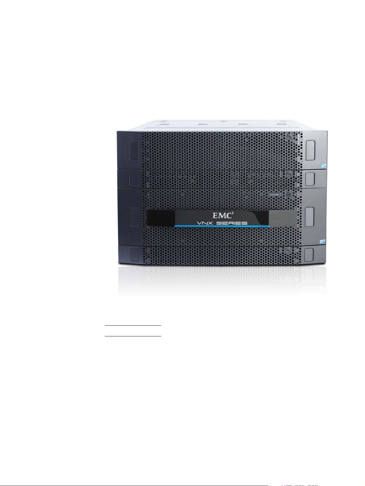
As a mid-range/entry level storage platform offering Block, File, and Unified services, the
VNX5300 platform (Figure 1) is one of the five models that make up the VNX series. For a
quick look at the VNX5300 platform hardware features, see Table 1, “VNX5300 hardware
feature quick reference,” on page 8.
Figure 1 Example of a Block and File (Unified) VNX5300 platform with front bezel
Note: A VNX5300 Block platform only includes an SPS and a DPE.
EMC VNX5300 Hardware Information Guide 5
Page 6
VNX5300 Block and File product description
VNX5300 Block and File product description
This section shows an example of the front and rear views of a Block and File (Unified)
VNX5300 platform.
Note: A fully configured Unified VNX5300 platform includes up to seven 3U DAEs (a
maximum of 120 3.5-inch disk drives) or up to four 2U DAEs (a maximum of 125 2.5-inch
disk drives).
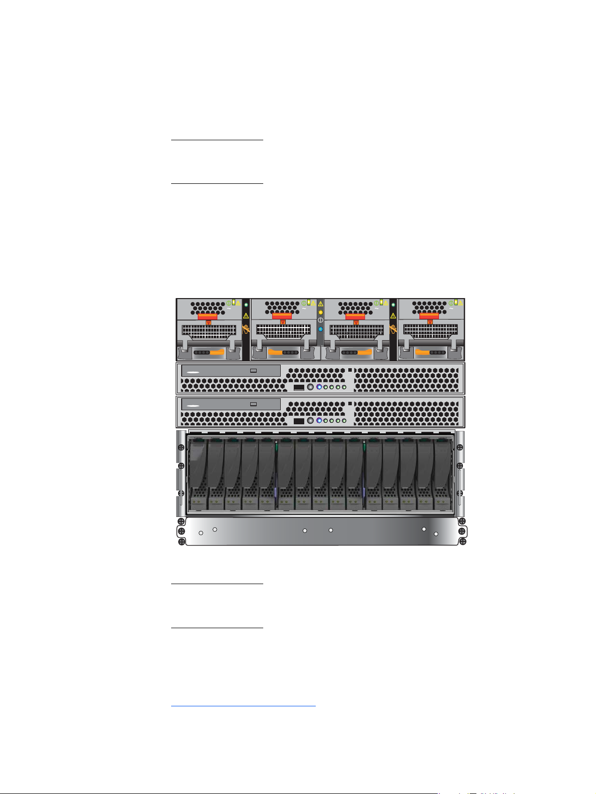
Front view
Figure 2 shows an example of the front view of a Block and File (Unified) VNX5300
platform having a dual 1U SPS, a 3U, 15 (3.5-inch) disk drive 3U DPE, two 1U Control
Stations (one optional), and one 2U Data Mover Enclosure with two Data Movers
Data Mover includes two power supply/cooling (fan) modules and one CPU module.
2
. Each
AC
AC
AC
AC
Data Mover
Enclosure 0
DVD
Control Station 1
(optional)
DVD
Control Station 0
3U, 15 (3.5-inch)
disk processor
enclosure (DPE)
SPS
VNX-000562
Figure 2 Example of a Block and File VNX5300 (Unified) platform with a 3U, 15 DPE (front view)
Note: Figure 2 and Figure 3 on page 7 are examples of a Block and File (Unified) VNX5300
platform (front and rear views). These figures are example of what a Block and File
(Unified) VNX5300 platform looks like and are for illustrative purposes only.
2. The term Data Mover is used throughout this guide. The term Data Mover is also referred to as a
blade. These terms are interchangeable and mean the same thing.
6 EMC VNX5300 Hardware Information Guide
Page 7
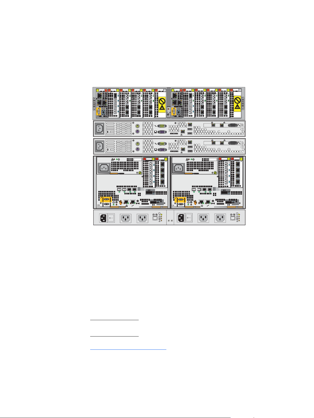
Rear view
VNX5300 Block and File product description
Figure 3 shows an example of the rear view of a Block and File (Unified) VNX5300 platform
having a dual 1U SPS, a 3U DPE with two storage processors (SP A and B), two (one
optional) 1U Control Stations, and one 2U Data Mover Enclosure with two Data Movers.
Each Data Mover includes two power supply/cooling (fan) modules and one CPU module.
Data Mover
123
0
23
1
0
12 3
0
PART NUMBER
REV A09 A
12 301
0
PART NUMBER
REV A09 A
23
23
12 3
123
0
CS
A
CS
A
1
0
0
B
MGMT
B
MGMT
PART NUMBER
REV A09 A
12 3
0
PART NUMBER
REV A09 A
23
1
Enclosure 0
0
Control Station 1
(optional)
Control Station 0
Hardware features
123
B
8Gb
6Gb
bre
SAS
5
4
2
3
0
X4
1
6Gb SAS
0 X4
0123
8Gb
bre
5
4
2
3
123
0
6Gb
SAS
X4
1
6Gb SAS
0 X4
Disk
0123
A
processor
enclosure
SPS
VNX-000563
Figure 3 Example of a Block and File (Unified) VNX5300 platform (rear view)
Contained in a 7 to 8U architecture, the Block and File (Unified) VNX5300 platform weighs
approximately 206.7 lb (93.76 kg) to 229.7 lb (104.19 kg) fully loaded
3
depending on the
type of disk drives used in the 3U DPE. With the 2U DME having the deepest dimension
within the cabinet, the Block and File (Unified) VNX5300 measures 12.25 to 14 inches (7
to 8U) high x 18.92 inches wide x 24.25 inches deep (31.11 to 35.56 cm x 48.05 cm x
61.59 cm). Between the front and rear of the enclosure, a midplane distributes power and
signals to all the enclosure components. The CPU modules and the power supply modules
plug directly into the midplane connections.
Note: The previously mentioned dimensions are approximate and do not include the
cabinet enclosure.
3. A fully loaded Block and File (Unified) VNX5300 platform (without any DAEs) includes two 1U
Control Stations, a 3U DPE (with two SPs), one dual 1U SPS, and one 2U Data Mover Enclosure
with one to two Data Movers. In this fully loaded Block and File (Unified) VNX5300 platform, the
DPE (with two SPs) can have either 15 (3.5-inch) drives or 25 (2.5-inch) drives. Separately, the 15
(3.5-inch) drives weigh 34 lb (15.42 kg) and the 25 (2.5-inch) drives weigh 13.5 lb (6.13 kg),
respectively.
EMC VNX5300 Hardware Information Guide 7
Page 8
VNX5300 Block and File product description
IMPORTANT
Minimum
form
factor
4U-7U 125 3.5 in.
1. MPFS = Multi-Path File System
2. pNFS = parallel-NFS
3. BE = back end
Maximum
# of
drives
Drive
types
SAS,
NL-SAS,
Flash,
and 2.5
in. 10 K
SAS
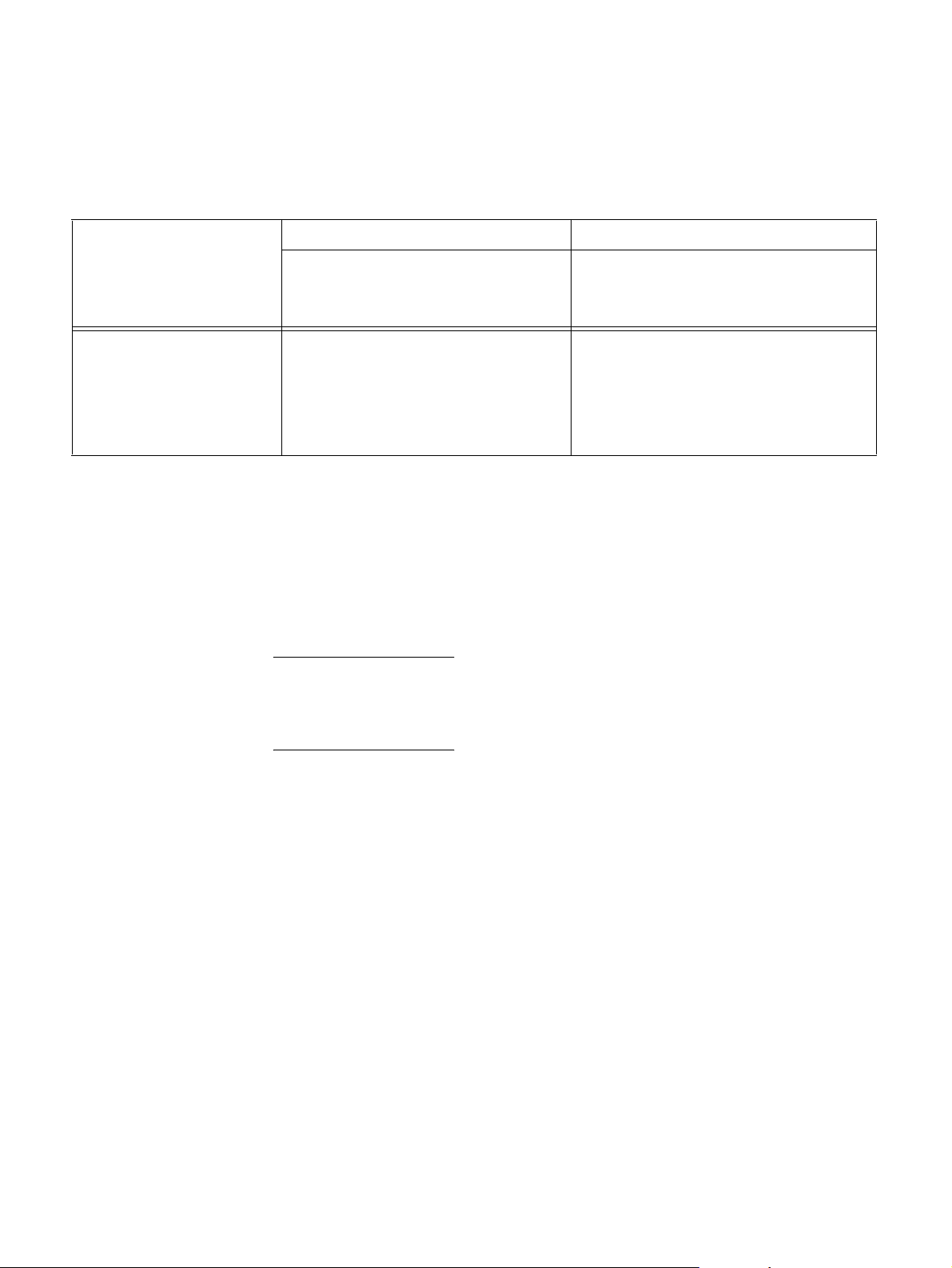
For physical, environmental, and power details, refer to the
Technical Specifications and Operating Limits
Table 1 VNX5300 hardware feature quick reference
File Block
Config.
I/O slots
per Data
Mover
3 1 or 2 6 GB NFS,
Data
Movers
System
memory
per Data
Mover Protocols
CIFS,
MPFS
and
pNFS
1
2
document.
Config.
I/O
slots
per SP
24 FC
VNX5300 Storage System
System
Built-in
I/O ports SPs
ports
plus 2
3
BE
SAS
ports
memory
per SP Protocols
2 12 GB FC, iSCSI,
and FCoE
Configured for AC-input power, the Block and File (Unified) VNX5300 platform includes
the following hardware features:
◆ One 3U DPE:
On the rear of the 3U DPE, each storage processor includes a CPU module and a power
supply. Two latch handles on the bottom left and right provide each SP (SP A and SP B)
with the means to secure the SP. The CPU and power supply modules can only be installed
or removed after you remove the entire storage processor from the 3U DPE.
• On the front of the 3U DPE, three types of disk drives are supported in two disk
drive carrier types; 3U, 15 (3.5-inch) disk drive carrier (Figure 4 on page 13) or 3U,
25 (2.5-inch) disk drive carrier (Figure 5 on page 14). The disk drives supported are
Serial attached-SCSI (SAS), near-line SAS (NL-SAS), and Flash.
• On the rear of the 3U DPE, each (hot-swappable) storage processor (Figure 11 on
page 22) consists of:
– A CPU module with an Intel Xeon 4-core 1.66-GHz processor with three Double
Data Rate Three (DDR3) synchronous dynamic RAM (SDRAM) slots supporting
4-GB of SDRAM for a total of 12 GB per SP
– Four integrated 8-Gb/s FC ports (labeled 2, 3, 4, and 5) supporting 2, 4, and
8 Gb/s having front end auto-negotiation with support for manual override
– Two integrated 6-Gb/s SAS x4 ports (labeled 6Gb SAS 0 x4 and 1 x4);
supported speeds are 1.5, 3, and 6 Gb/s
8 EMC VNX5300 Hardware Information Guide
Page 9

VNX5300 Block and File product description
– Two PCI Gen 2 x4 I/O module slots supporting a combination of the following
UltraFlex
a.) Two-port 10-Gb/s optical or active Twinax
™
I/O modules:
4
(w/iSCSI protocol); labeled
10 GbE on the latch handle
b.) Two-port 10-Gb/s RJ-45 Base-T iSCSI/IP; labeled 10 GbE Base-T on the latch
handle
Note: The two-port 10-Gb/s RJ-45 Base-T/IP I/O module requires VNX OE for File
version 7.1 or later.
c.) Four-port 1-Gb/s copper iSCSI; labeled 1 GbE iSCSI/TOE on the latch handle
d.) Four-port 8-Gb/s optical Fibre Channel (running at 2, 4, or 8-Gb/s); labeled
8 GbE Fibre on the latch handle
e.) Two-port 10-Gb/s optical or active Twinax
3
Fibre Channel over Ethernet
(FCoE); labeled 10 GbE/FCoE on the latch handle
Note: The two-port 10-Gb/s optical or active Twinax FCoE I/O module requires
VNX OE for File version 7.0.35.3 or later.
– One RS-232/EIA 232 serial (up to 115 K baud) service laptop (micro DB-9) port
– One RS-232/EIA 232 serial management (micro DB-9) port
– One 10/100/1000 LAN management (RJ-45) port
– One 10/100/1000 LAN service (RJ-45) port
– One power supply (hot-swappable)
◆ One 1U standby power supply (SPS) with a second (optional) SPS available
◆ One 2U DME with up to two Data Movers. Each Data Mover consists of:
• One CPU module consisting of one Intel Xeon 4-core 2.13-GHz processor
• Six DDR3 synchronous dynamic RAM (SDRAM) slots supporting up to 6 GB per CPU
module
• One Fibre Channel (FC) I/O module with a:
– Four-port 8 Gb/s optical (running at 2, 4, or 8 Gb/s); in slot 0; labeled
8 GbE Fibre on the latch handle
• One to two of the following network I/O modules in any combination:
– Two-port 10-Gb/s optical or active Twinax
4
; labeled 10 GbE v2 on the latch
handle
– Two-port 10-Gb/s optical or Twinax
4
; labeled 10 GbE v3 on the latch handle
Note: Version 3 of the two-port 10-Gb/s optical or active Twinax I/O module
requires VNX OE File version 7.1 or later.
– Four-port 1-Gb/s copper; labeled 1 GbE on the latch handle
4. The two-port 10-Gb/s and FCoE I/O modules can also use active twinaxial (Twinax) cables. Twinax
is a type of cable similar to coax, but with two inner conductors instead of one. These cables will
be supplied in lieu of SFP+ transceiver modules when so ordered.
EMC VNX5300 Hardware Information Guide 9
Page 10

VNX5300 Block and File product description
IMPORTANT
◆ One or two Control Stations. Each Control Station consists of the following features:
– Two-port 1-Gb/s copper plus two-port 1-Gb/s optical; labeled 1 GbE on the
latch handle
– Two-port 10-Gb/s RJ45 Base-T iSCSI/IP; labeled 10 GbE Base-T on the latch
handle
Note: The two-port 10-Gb/s RJ-45 Base-T/IP I/O module requires VNX OE for File
version 7.1 or later.
• Two management modules per DME (or, one per Data Mover)
• Two power supply/cooling (fan) modules per CPU module
• Intel 2.0 GHz single core Celeron processor with 800-MHz front side bus (FSB) and
512 KB cache
• 2 GB of RAM
• One 250-GB SATA hard drive
• Two rear-mounted USB ports and one front-mounted USB port
• Four 10BASE-T/100BASE-TX/1000BASE-T network interface (RJ-45) connectors
(located on the rear panel)
• Two integrated serial ports, one for laptop/console redirection and one for the
CallHome modem
• One DVD-ROM drive
◆ Expansion of up to seven 3U, 15 (3.5-inch) DAEs (a maximum of 120 drives) or up to
four 2U, 25 (2.5-inch) DAEs (a maximum of 125 drives)
When calculating the number of drives for your Block and File (Unified) VNX5300 platform,
the 3U DPE is included in the total drive slot quantity of 120 to 125 drives. If the total drive
slot quantity exceeds 120 or 125, you will not be able to add another DAE. Refer to
“Disk-array enclosure” on page 68 for more information about the available expansion
DAEs for the Block and File (Unified) VNX5300 platform.
◆ Any required cables including LAN cables, modem cables, and serial DB-9 cable.
◆ Mounting rails with hardware
◆ Front bezel with VNX5300 badge
10 EMC VNX5300 Hardware Information Guide
Page 11

System component description
IMPORTANT
This section describes the Block and File (Unified) VNX5300 platform components. These
details include illustrations and descriptions of the front and rear connectors as well as
the LED indicators.
Note: In the following sections, the illustrations and corresponding tables describe these
individual components. These descriptions are for illustrative purposes only.
VNX5300 front view
As previously described, the Block and File (Unified) VNX5300 platform is made up of a
3U DPE, a 1U SPS, one to two 1U Control Stations, and one 2U DME. The following
sections will describe the front (Figure 2 on page 6) view of the VNX5300 platform
components.
DPE front views
The Block and File (Unified) VNX5300 platform can have one of two versions of the
available 3U disk drive DPEs.
System component description
When calculating the number of drives for your Block and File (Unified) VNX5300 platform,
the DPE is included in the total drive slot quantity of 120 to 125 drives. If the total drive
slot quantity exceeds 120 or 125, you will not be able to add another DAE. Refer to the
“Disk-array enclosure” section on page 68 for more information about the available
expansion DAEs for the Block and File (Unified) VNX5300 platform.
Each Block and File (Unified) VNX5300 platform 3U DPE consists of the following
components:
◆ Drive carrier
◆ Disk drives
◆ Midplane
◆ Storage processor (SP) CPU
◆ Storage processor (SP) power supply
◆ EMI shielding
Drive carrier
The disk drive carriers are metal and plastic assemblies that provide smooth, reliable
contact with the enclosure slot guides and midplane connectors. Each carrier has a
handle with a latch and spring clips. The latch holds the disk drive in place to ensure
proper connection with the midplane. Disk drive activity/fault LEDs are integrated into the
carrier. The “3U, 15 (3.5-inch) DPE” section on page 12 or the “3U, 25 (2.5-inch) DPE”
section on page 14 provides more information.
EMC VNX5300 Hardware Information Guide 11
Page 12

System component description
Disk drives
Each disk drive consists of one disk drive in a carrier. You can visually distinguish
between disk drive types by their different latch and handle mechanisms and by type,
capacity, and speed labels on each disk drive. You can add or remove a disk drive while
the DPE is powered up, but you should exercise special care when removing disk drives
while they are in use. Disk drives are extremely sensitive electronic components.
Midplane
A midplane separates the front-facing disk drives from the rear-facing SPs. It distributes
power and signals to all components in the enclosure. SPs and disk drives plug directly
into the midplane.
Storage processor (SP)
The SP is the intelligent component of the 3U disk processor enclosure (DPE). Acting as
the control center, each SP includes status LEDs, PCI Gen 2 I/O module slots, and LAN
ports. The “DPE” section on page 25 provides more information.
Storage processor (SP) power supply
3U, 15 (3.5-inch) DPE
The SP power supply is located on the top, left side of the SP when viewed from the rear.
This module is an auto-ranging, power-factor-corrected, multi-output, off-line converter
with its own line cord. Each power supply includes status LEDs. A latch on the power
supply locks it into place to ensure proper connection. The “SP AC power supply” section
on page 27 provides more information.
EMI shielding
EMI compliance requires a properly installed electromagnetic interference (EMI) shield in
front of the DPE disk drives. When installed in cabinets that include a front door, the DPE
includes a simple EMI shield. Other installations require a front bezel that has a locking
latch and integrated EMI shield. You must remove the bezel/shield to remove and install
disk drive modules.
On the front, the Block and File (Unified) VNX5300 platform 3U, 15 (3.5-inch) DPE carrier
includes the following:
◆ 3.5-inch 6-Gb/s SAS or 6-Gb/s NL-SAS disk drives (hot-swappable)
◆ Status LEDs
12 EMC VNX5300 Hardware Information Guide
Page 13

Figure 4 shows the location of these disk drives and Status LEDs.
System component description
1
1 3.5-inch 6-Gb/s SAS drives or 6-Gb/s
23
5
4
4 Disk drive fault LED (amber)
VNX-000103
NL-SAS disk drives
2 DPE fault LED (amber) 5 Disk drive on/activity LED (green)
3 DPE power on LED (blue)
Figure 4 VNX5300 platform 3U, 15 DPE carrier (front view)
Table 2 describes the Block and File (Unified) VNX5300 platform 3U, 15 DPE and the disk
drive status LEDs.
Table 2 VNX5300 platform 3U, 15 DPE and disk drive LEDs
LED Color State Description
DPE fault (location 2) Amber On Fault has occurred
Note: LED is always on at
powerup, until it is initialized.
DPE power (location 3) Green On Powering and powered up with
backend bus running at 2 Gb/s
Blue On Powering and powered up with
backend bus running at 6Gb/s
— Off Powered down
Disk drive fault (location 4) Amber On Fault has occurred
— Off No fault has occurred
EMC VNX5300 Hardware Information Guide 13
Page 14
System component description
24
0
12345678910 11 12 13 14 15 16 17 18 19 20 21 22 23 24
0
Table 2 VNX5300 platform 3U, 15 DPE and disk drive LEDs (continued)
LED Color State Description
3U, 25 (2.5-inch) DPE
Disk drive on/activity
Green On Powering and powered up
(location 5)
Blinking, mostly onDisk drive is on with I/O activity
Blinking at
constant rate
Blinking, mostly
off
Disk drive is spinning up or down
normally
Disk drive is powered up but not
spinning
Note: This is a normal part of the
spin-up sequence, occurring
during the spin-up delay of a
slot.
— Off Disk is powered down
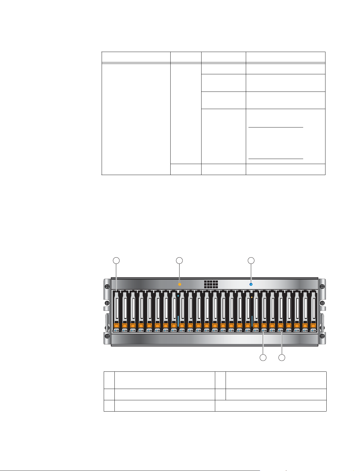
On the front, viewing from left to right, the Block and File (Unified) VNX5300 platform 3U,
25 (2.5-inch) disk drive DPE includes the following:
◆ 2.5-inch 6-Gb/s SAS or 6-Gb/s NL-SAS drives (hot-swappable)
◆ Status LEDs
Figure 5 shows the location of these disk drives and status LEDs.
1
1 2.5-inch 6-Gb/s SAS or 6-Gb/s NL-SAS
disk drives
2 DPE fault LED (amber) 5 Disk drive status/activity (blue)
3 DPE power status LED (blue)
2
3
45
VNX-000281
4 Disk drive fault LED (amber)
Figure 5 VNX5300 platform 3U, 25 DPE carrier (front view)
14 EMC VNX5300 Hardware Information Guide
Page 15
System component description
Table 3 describes the Block and File (Unified) VNX5300 platform 3U, 25 DPE and disk
drive status LEDs.
Table 3 VNX5300 platform 3U, 25 DPE and disk drive status LEDs
LED Color State Description
DPE fault (location 2) Amber On Fault has occurred
DPE power (location 3) Blue On Powering and powered up
— Off Powered down
Disk drive fault (location 4) Amber On Fault has occurred
— Off No fault has occurred
Control Station front view
Disk drive on/activity
Blue On Powering and powered up
(location 5)
Blinking Disk drive activity
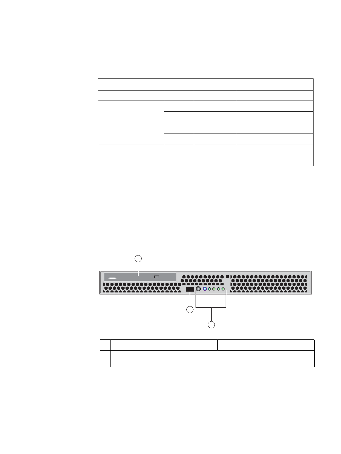
On the front, the Block and File (Unified) VNX5300 platform 1U Control Station includes
the following:
◆ DVD-ROM drive
◆ USB 2.0 connector (not used)
◆ Control switch and status LEDs
Figure 6 shows the orientation of these components.
1
DVD
3
2
1 DVD-ROM drive 3 USB 2.0 connector (not used)
2 Control Station switch and status LEDs (for
a closer view, see Figure 7 on page 16)
Figure 6 VNX5300 platform Control Station (front view)
EMC VNX5300 Hardware Information Guide 15
CNS-001740
Page 16
System component description
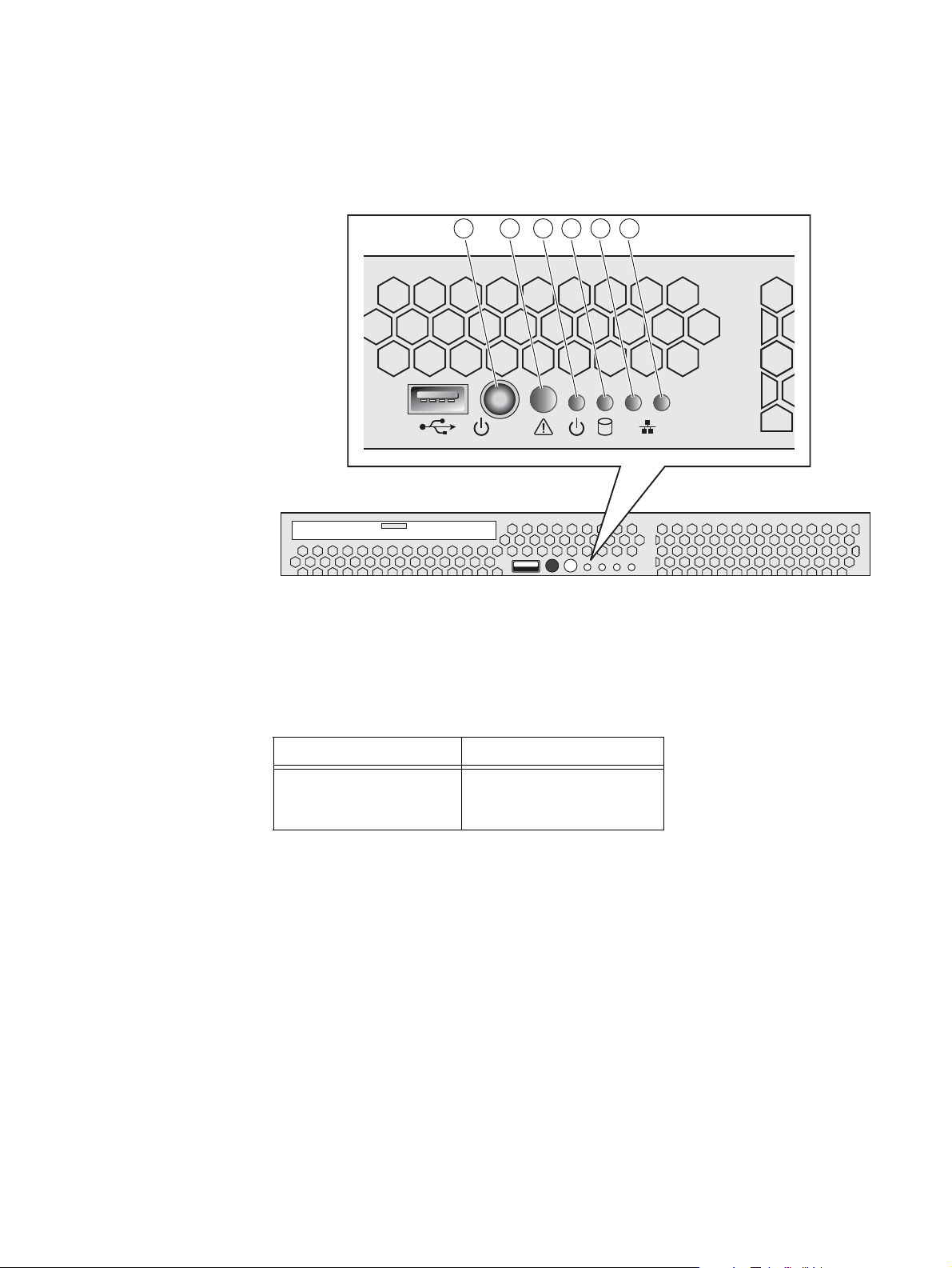
Control Station switch and LEDs
Figure 7 on page 16 shows the location of the Block and File (Unified) VNX5300 platform
1U Control Station switch and LEDs on the front panel.
21 3 4 5 6
12
Figure 7 VNX5300 platform Control Station switch and LEDs
Table 4 on page 16 describes the switch located on the front panel.
Table 4 Control Station switch
Switch Description
Power push-button
(location 1)
Toggles the 1U Control Station
power (push in and hold for
about 10 seconds)
Table 5 on page 17 describes the LEDs located on the front panel.
CNS-001744
16 EMC VNX5300 Hardware Information Guide
Page 17
System component description
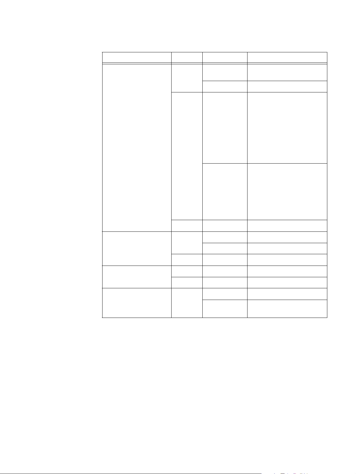
Table 5 Control Station LEDs
LED Color State Description
System status/boot
(location 2)
System power/sleep or
standby (location 3)
Green On Power on/system loaded and
ready
Blinking Booting up
1
or system degraded
Amber On Critical, non-recoverable error;
system has failed due to:
• Themtrip asserted
• IERR asserted
• Non-recoverable temperature
threshold asserted.
• Non-recoverable voltage
asserted.
• Power fault/Power control
failure
Blinking Non-fatal alarm; system is likely
to fail due to:
• Critical temperature threshold
asserted.
• Critical voltage threshold
asserted.
• Critical fan threshold
asserted.
—Off Power off
Green On Power on
Blinking Sleep (standby)
—Off Power off
Internal hard drive activity
Green Blinking Hard drive access
(location 4)
— Off No hard drive activity
Onboard (integrated)
Green On NIC link/no access
Ethernet NIC 1 and 2
(locations 5 and 6,
Blinking NIC link/LAN access
respectively)
1. The system status LED flashes green while booting up.
EMC VNX5300 Hardware Information Guide 17
Page 18
System component description
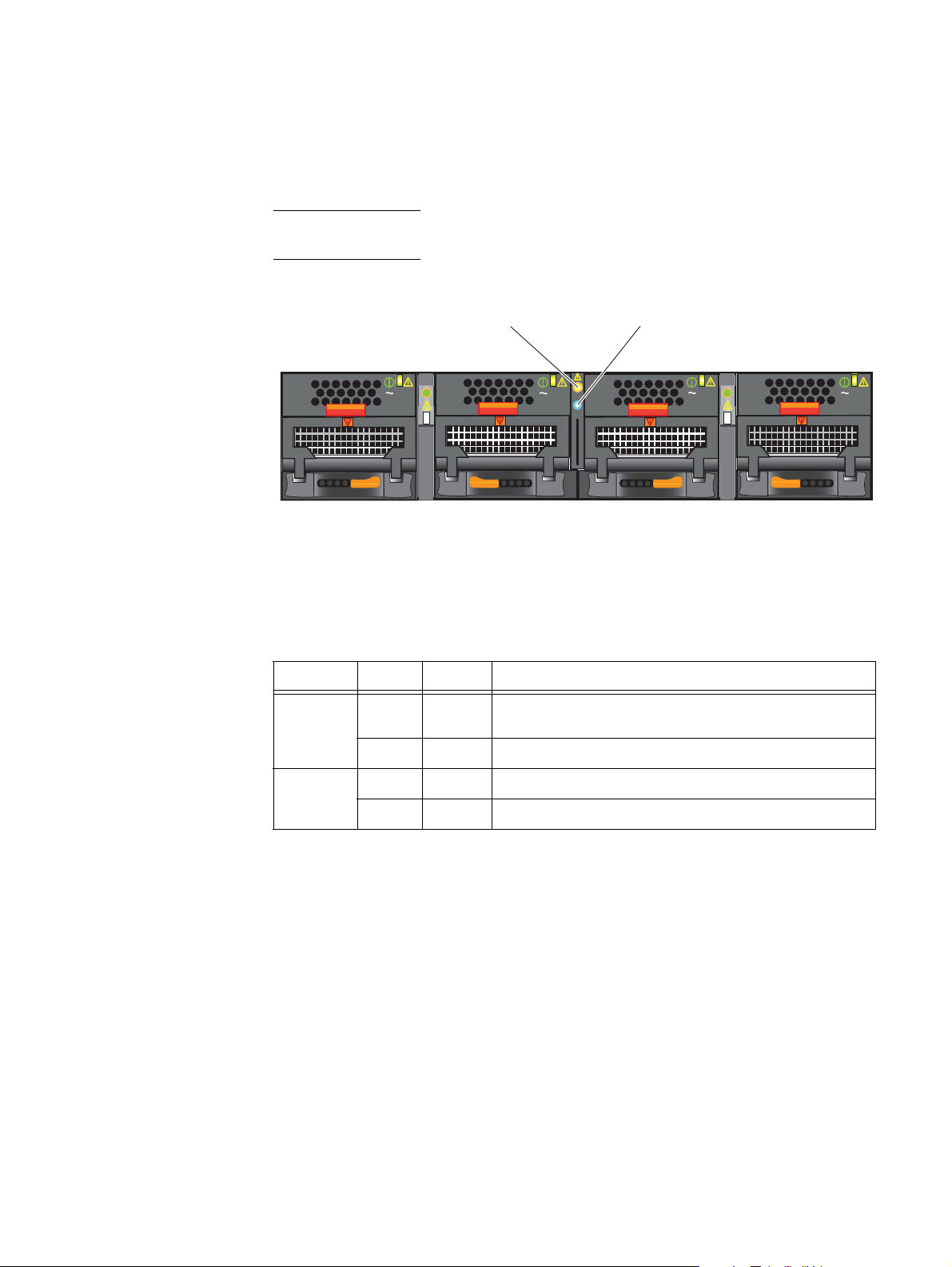
DME front view
The front of the Block and File (Unified) VNX5300 platform, the 2U DME contains two
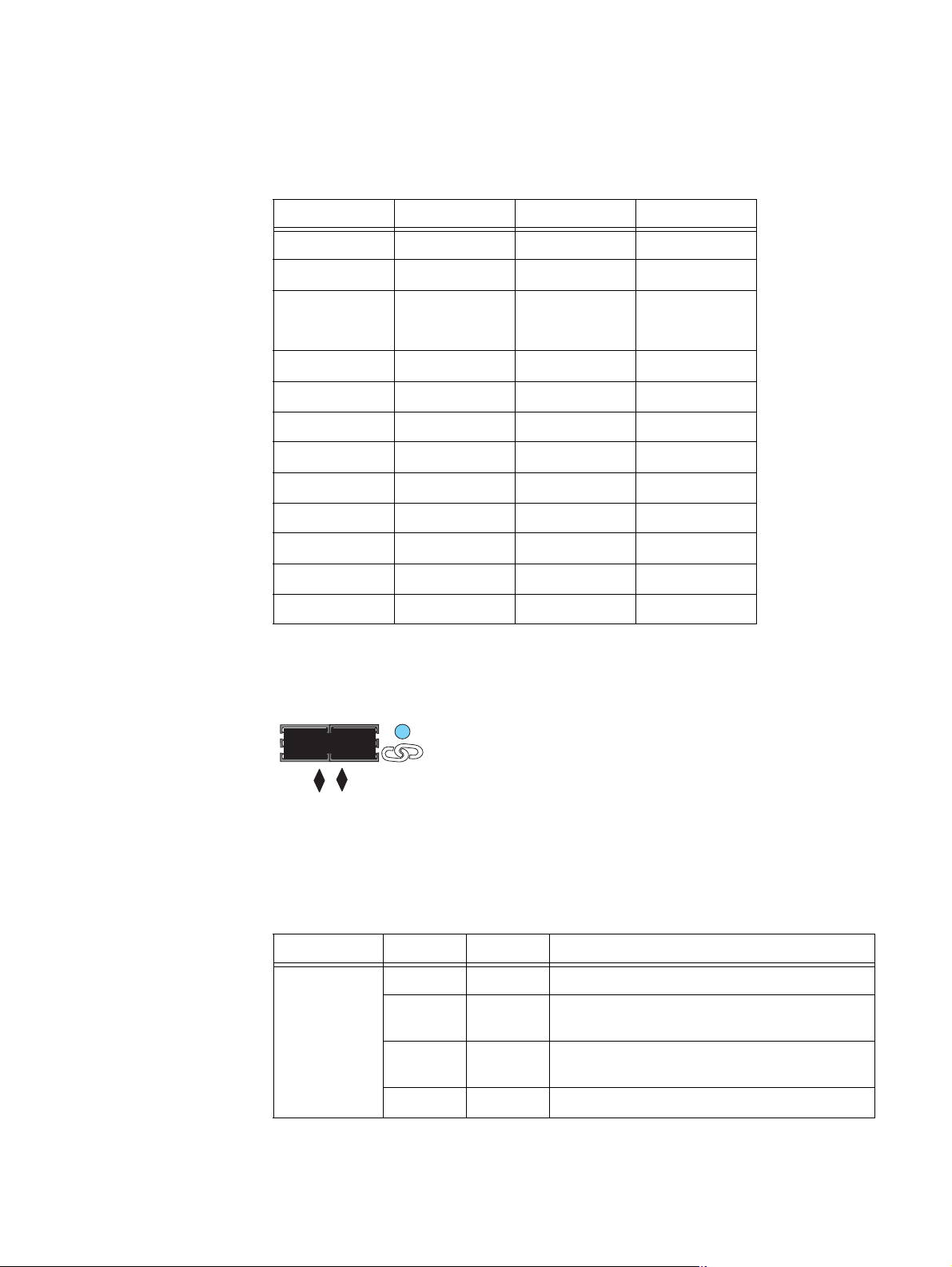
enclosure status (power and fault) LEDs (Figure 8).
Note: Figure 8 is an example of a Block and File (Unified) VNX5300 platform 2U DME with
four power supply/cooling (fan) modules and two CPU modules installed.
Data Mover enclosure
fault LED
AC
AC
Data Mover enclosure
power LED
AC
CNS-001667
Figure 8 Data Mover enclosure LEDs
Table 6 describes the 2U DME power and fault LEDs.
Table 6 Data Mover Enclosure LEDs
LED Color State Description
Power Blue On DME is powered up and all the components in the enclosure
are operating properly
— Off DME is powered down.
AC
Fault Amber On A replaceable component failed within the enclosure.
— Off DME operating normally.
18 EMC VNX5300 Hardware Information Guide
Page 19
System component description
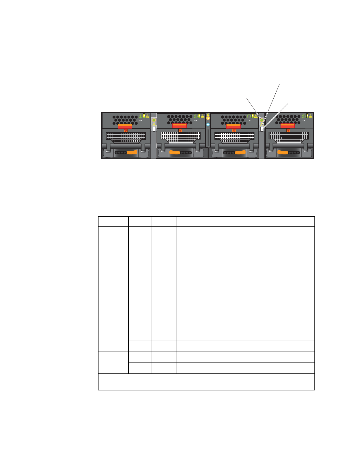
CPU LEDs
The CPU modules in the DME contain the power, fault, and unsafe-to-remove LEDs.
Figure 9 shows the CPU LEDs.
CPU fault LED
CPU power LED
AC
AC
AC
CPU unsafe to
remove LED
Figure 9 CPU LEDs
Table 7 describes the 2U DME CPU power and fault LEDs.
Table 7 CPU LEDs
LED Color State Description
Power Green On Data Mover is powered up and all components in the Data
Mover are operating properly.
— Off Data Mover is powered down.
Fault Amber On Data Mover has faulted.
AC
CNS-001669
Blinking Data Mover goes through six stages of power up:
1. Executes a BIOS check, blinking once every 4 seconds
2. Executes a POST check, blinking once every second
3. Loads the operating system, blinking four times a second
Blue
(see
Note)
4. Operating system loaded, blinking once every 4 seconds
5. Operating system starting drivers, blinking once every
second
6. Operating system drivers operating, blinking four times a
second
— Off Data Mover operating normally.
Unsafe-to-
White On Data Mover is unsafe to remove.
remove
— Off Data Mover is safe to remove.
Note: The fault LED changes color from amber to blue when the operating system is loading, see
step 4 in the description.
EMC VNX5300 Hardware Information Guide 19
Page 20
System component description
Power supply/cooling (fan) module LED
The power supply/cooling (fan) modules have a status LED on the front. Figure 10 shows
the LEDs for the power supply/cooling (fan) modules.
Power supply/
cooling (fan) power/fault LED
VNX5300 rear view
AC
AC
AC
AC
CNS-001673
Figure 10 Power supply/cooling (fan) module LED
Table 8 describes the power supply/cooling module (fan) status LED.
Table 8 Power supply/cooling (fan) module LED
LED Color State Description
Power/Fault Green On Normal (no faults detected)
Amber Blinking Power supplied but external fault detected
Amber On No power
On the rear, a Block and File (Unified) VNX5300 platform includes the following hardware
components:
◆ One to two 1U SPSs
◆ One 3U DPE with two storage processors (SPs), each SP (A and B) having one CPU
module and one power supply
◆ One to two 1U Control Stations
◆ One 2U Data Mover Enclosure with one to two Data Movers
Standby power supply rear view
The Block and File (Unified) VNX5300 platform includes one to two 1U, 1.2-kilowatt
standby power supplies (SPSs) to maintain power to the Block and File (Unified) VNX5300
platform SP during power loss. Within the SPS, a built-in DC battery pack is charged by
way of an AC-DC converter. AC input power from the power distribution unit (PDU) goes
into the SPS AC power inlet to the AC-DC converter. This converter then converts the AC
power to DC power, which is then stored into the built-in DC battery pack. When
emergency power is needed by the Block and File (Unified) VNX5300 platform SP, a
20 EMC VNX5300 Hardware Information Guide
Page 21

System component description
IMPORTANT
second DC-AC converter inside the SPS takes the DC power from the DC battery pack and
then converts it to AC power. This AC power then goes from the SPS AC power outlet to the
Block and File (Unified) VNX5300 platform SP (Figure 11 on page 22).
Note: Two SPSs provide higher availability and allow write caching, which prevents data
loss during a power failure, to continue.
A faulted or not fully charged SPS disables the write caching.
If AC power fails, the SPS provides backup power until the SP has flushed its write cache
data to the DAE disks. The SP then shuts off SPS power. If the cache flush has not
completed within 90 seconds—more than enough time to flush a full cache—or if the SP
has failed, then the SPS shuts down to prevent a deep discharge. If no AC input power is
available and the SPS is shut down, all the status lights will be off.
The output voltage, when the SPS is in the On-Line state, is a straight pass-through of the
AC-line from inlet to outlets. When in the On-Battery state, the output voltage shall be at
an AC level within the specified limits (see the SPS battery LED in Table 9 on page 23).
Two SPSs
When power returns, the SPS starts recharging the DC battery pack. It might reach a state
of full charge relatively quickly. If power remains off for a long period—days or weeks—the
DC battery might require more time to charge fully.
5
The storage processor will not use the
write cache unless it detects at least one fully charged SPS.
Battery lifetime depends on the number of discharge cycles and the depth of discharge. In
a typical environment, a battery pack can last 3 to 5 years. The DC battery pack lifetime is
shorter in locations that have frequent AC outages.
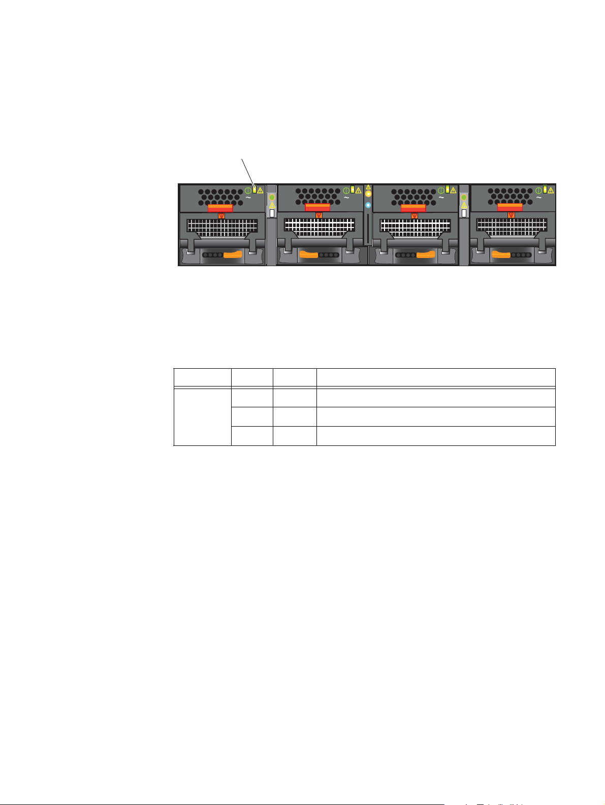
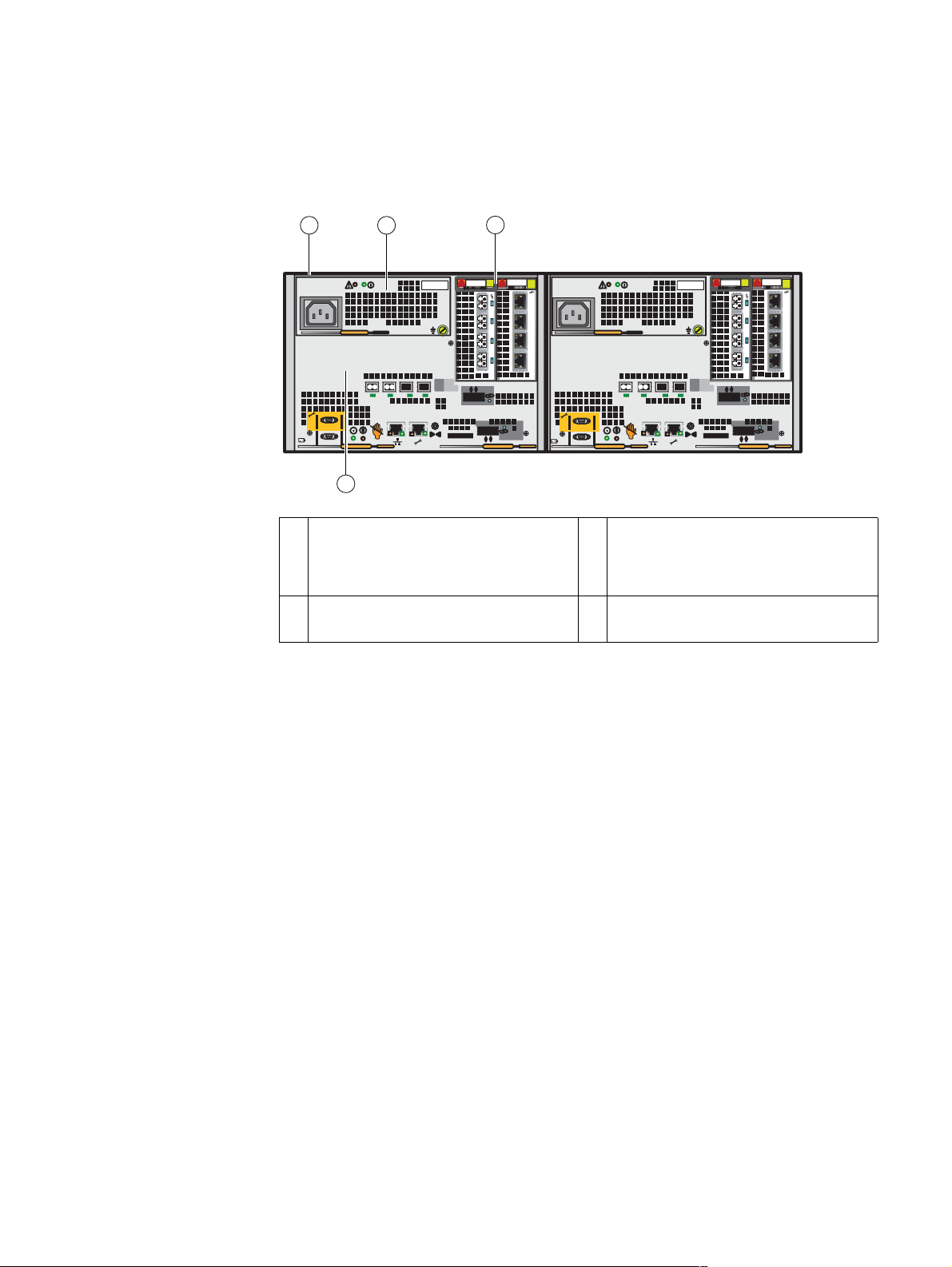
Looking from left to right, Figure 11 on page 22 shows an example of the rear view of two
SPSs (B and A, respectively).
An additional SPS can be added for redundancy. When only one SPS is used, the AC
power out connectors for the SPS supply AC power to both SP A and SP B.
It is important to cable each SPS so that it connects completely to either the A side or the
B side. For example, if you are looking at the SPSs from the rear, they should be
configured as:
◆ SPS A (rear, right side)—Power-out and sense (management) cables connected to the
SP A power supply.
◆ SPS B (rear, left side)—Power-out and sense (management) cables connected to the
SP B power supply.
5. After a full power outage, an SPS typically requires 45 minutes or a maximum of 75 minutes to
charge. To charge the SPS after being off-line usually requires at least 2 hours.
EMC VNX5300 Hardware Information Guide 21
Page 22
System component description
Note: If an SPS is cabled with the SPS sense (management) cable going to the power
supply on SP A and the power-out cable going to the power supply on SP B (or the other
way around), an error condition will occur when the SPS is tested or when it is charging.
Looking from left to right, Figure 11 on page 22 shows an example of the rear view of a
dual 1U SPS (B and A, respectively).
1 4
32 65
S/N
900-XXX-0014 0082
A00REV
S/N
900-XXX-0014 0082
A00REV
SPS B (optional) SPS A
78910
VNX-000282
1 SPS B AC power in (recessed plug) 6 AC power out socket (not used or to DAE A)
2 AC power out socket (not used or to DAE B) 7 Four SPS A status LEDs (green and amber)
3 AC power out socket to the SP B power
supply on the DPE
8 SPS A to SP A management (RJ-12)
connector
4 SPS A AC power in (recessed plug) 9 Four SPS B status LEDs (green and amber)
5 AC power out socket to the SP A power
supply on the DPE
10 SPS B to SP B management (RJ-12)
connector
Figure 11 Example of SPS B and A viewing from left to right (rear view)
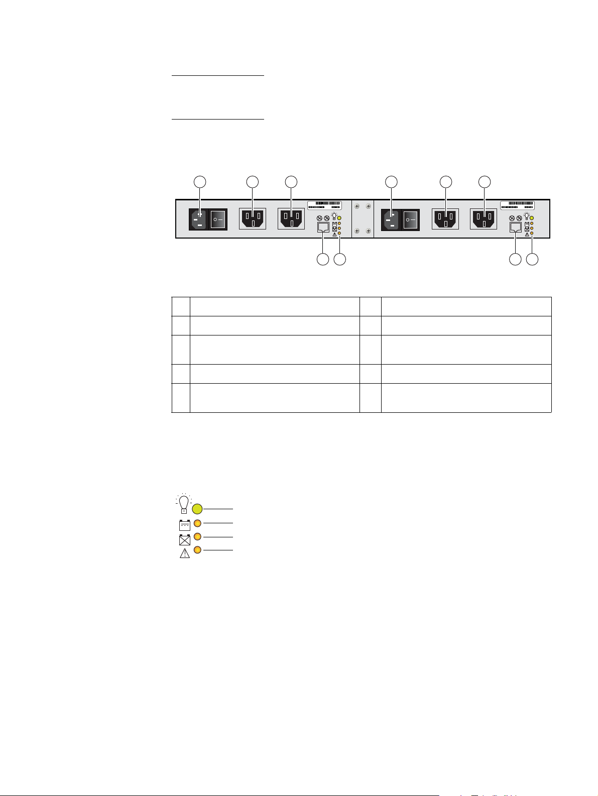
SPS LEDs
Figure 12 shows the LEDs located on each SPS (A and B).
Figure 12 SPS LEDs
22 EMC VNX5300 Hardware Information Guide
SPS power
SPS battery
SPS no battery
SPS fault
VNX-000289
Page 23
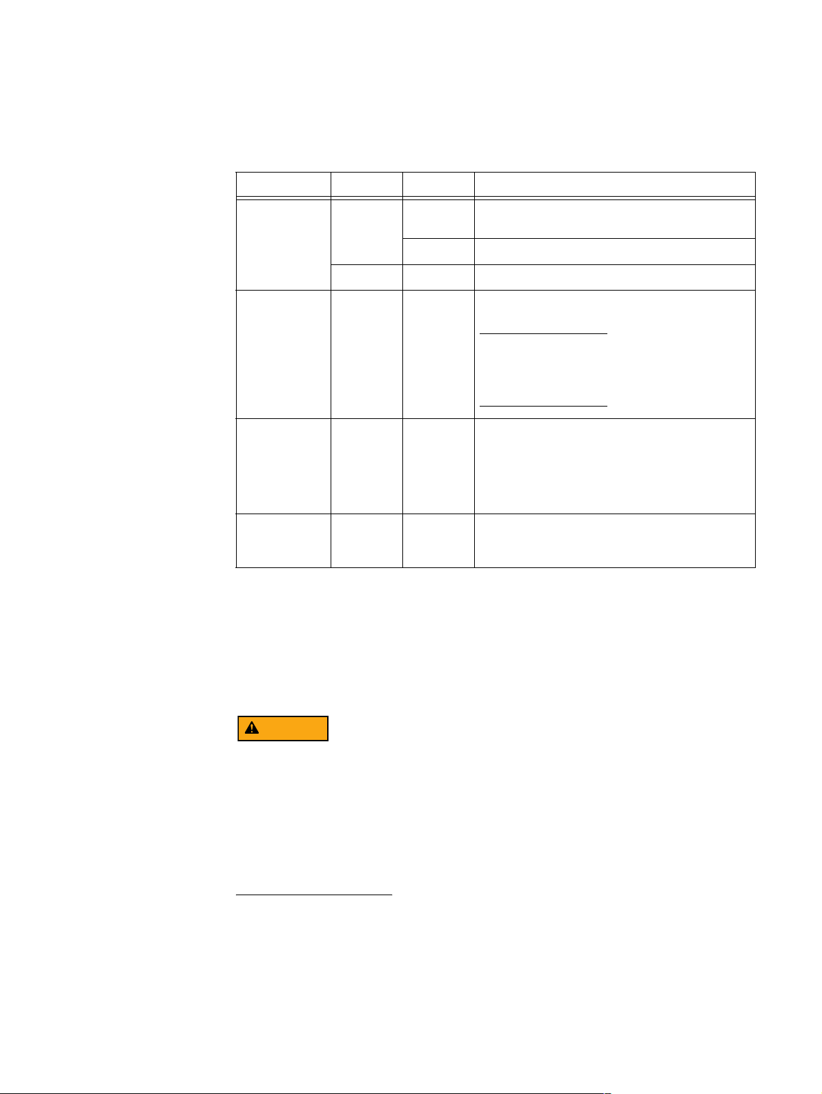
Table 9 describes the SPS LEDs.
Table 9 SPS LEDs
Led Color State Description
System component description
SPS RJ-12 connector
SPS power Green On SPS ready and operating normally; battery fully
charged
Blinking On/battery charging
— Off Off/disconnected
SPS battery Amber On AC line power is no longer available and the SPS is
supplying DC output power from the battery.
Note: When battery power comes on, and no other
online SPS is connected to the SP, the system writes
all cached data to disk, and the event log records
the event.
SPS no battery Amber On SPS battery is not fully charged and might not be
able to serve its cache flushing function. With the
battery in this state, and no other online SPS
connected to the SP, the system disables write
caching, and writes any modified pages to the disk
first. Replace the SPS as soon as possible.
SPS fault Amber On The SPS has an internal fault. The SPS might still be
able to run online, but write caching cannot occur.
Replace the SPS as soon as possible.
Figure 13 on page 24 shows the SPS (RJ-12 or modular jack) management port (labeled
with two symbols; one depicting a telephone handset with a line through it and the other
depicting a rectangle with a line through it). Both symbols mean that you cannot connect
telephone type circuits to this connector (see the following WARNING). This port connects
the SPS (A and B) ports to the SP (A and B) ports, respectively.
The SPS (RJ-12) port is a LAN port not a WAN port. LAN ports contain safety extra-low
voltage (SELV) circuits, and WAN ports contain telephone-network voltage (TNV) circuits.
An RJ-45 (or TNV-type) looks the same as the RJ-12 except for two very important
differences. An RJ-45 is an 8-wire modular jack. The RJ-12 is a six-wire modular jack. The
RJ-45 plugs and jacks are wider than their RJ-12 counterparts - 7/16" vs 3/8". An RJ-45
plug won't fit into an R-J12 jack. But an RJ-12 plug will fit into an RJ-45 jack. Use caution
when connecting cables. To avoid electric shock, do not attempt to connect TNV circuits
to SELV circuits.
EMC VNX5300 Hardware Information Guide 23
Page 24
System component description
VNX-000290
Figure 13 SPS RJ-12 port
Table 10 lists the SPS (RJ-12) pin signals used on the connector.
Table 10 SPS (RJ-12) port and connector pinout
RJ-45 pin Signal Description
1 RTS/DSR Ready to send Data transmit
ready
2 Shield Shield
3TXDTransmit data
4RXDReceive data
5GNDGround
6 CTS/DCD Clear to send Data
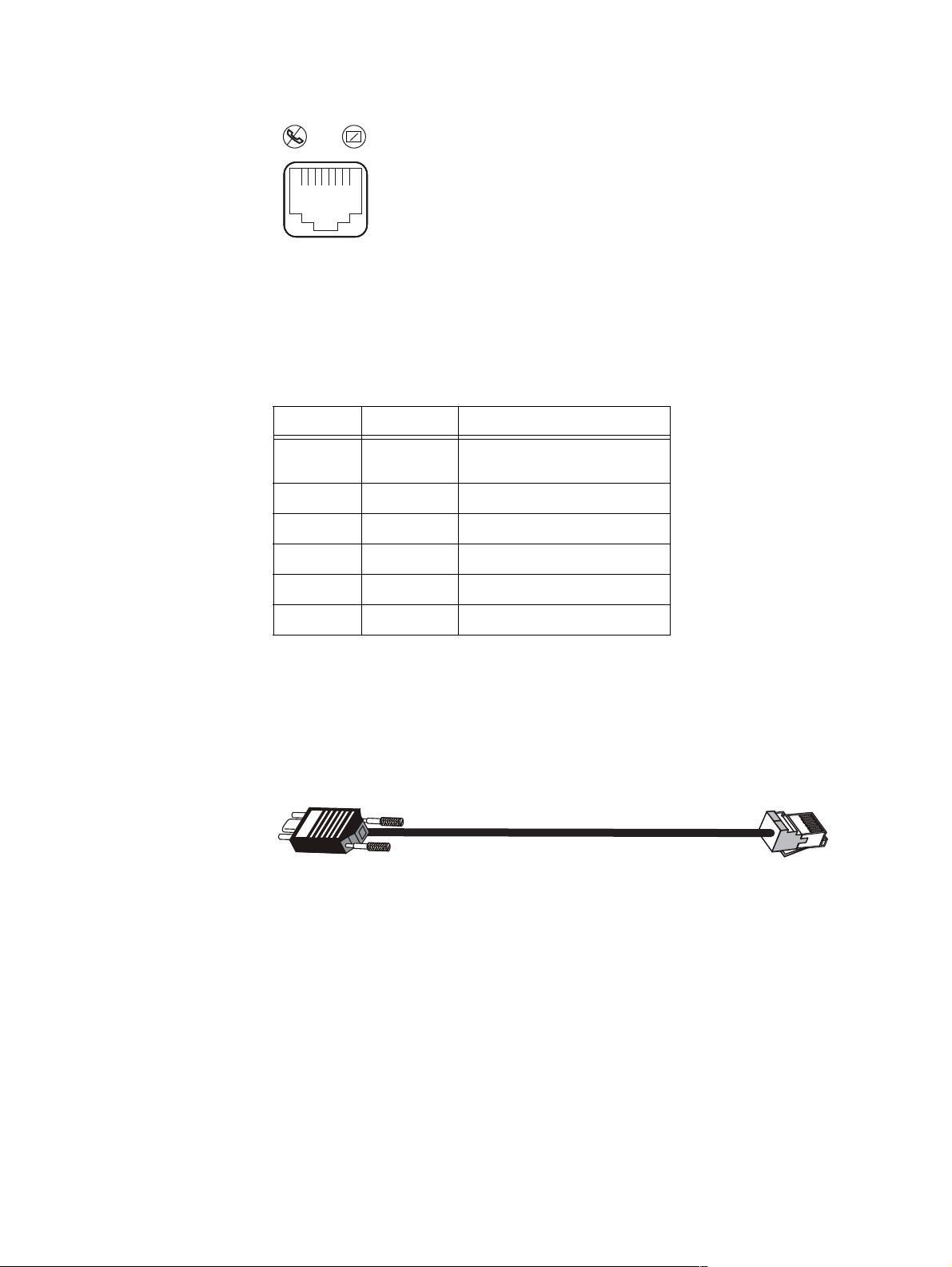
RJ-12 modular jack to micro DB-9 cable
The cable connecting the SPS to the SP is an RJ-12 to micro DB-9 cable (plug). It has an
RJ-12 connector (SPS side) on one end and a micro DB-9 connector (SP side) on the other
end. Figure 14 shows an example of an SPS A to SP A cable.
DB-9
Figure 14 Example of SP A (micro DB-9) to SPS (RJ-12) cable
RJ-12
VNX-000283
24 EMC VNX5300 Hardware Information Guide
Page 25
DPE rear view
System component description
Figure 15 shows an example of a DPE with two SPs and the location of the major hardware
components that make up each SP (A and B).
1 2
B
8Gb
bre
5
4
2
3
3
PART NUMB ER
PART NUMBER
PART NUMBER
REV A09 A
REV A09 A
123
0123
6Gb
SAS
0
X4
1
6Gb SAS
0 X4
2
5
4
3
PART NUMBER
REV A09 A
REV A09 A
123
0123
A
8Gb
bre
0
6Gb
SAS
X4
1
6Gb SAS
0 X4
SP B SP A
4
1 SP (for a closer view, see Figure 16 on
page 26)
3 I/O module slots showing a four-port
8-Gb/s Fibre Channel (FC) I/O module
VNX-000570
(supports 2, 4, and 8 Gb/s) and a four-port
1-Gb/s iSCSI I/O module
2 Power supply (for a closer view, see
Figure 17 on page 27)
4 CPU module (for a closer view, see
Figure 16 on page 26)
Figure 15 Example of the Block and File (Unified) VNX5300 platform DPE with two SPs (rear view)
DPE
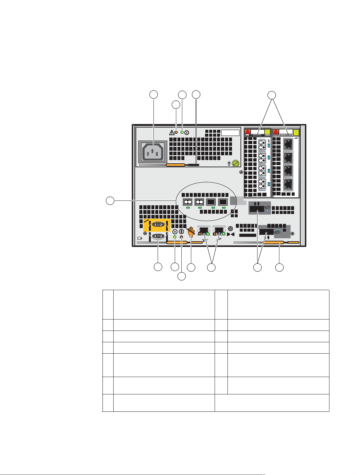
On the rear, viewing from left to right, each 3U DPE includes the following hardware
components:
◆ AC power supply/cooling module
• Power in (recessed) connector (plug)
• Power supply status LEDs (power on and fault)
• Power supply latch handle
◆ SP B and A
• Two PCI Gen 2 x4 I/O module slots (supporting several module types, see page 9)
• Two 6-Gb/s SAS x4 ports (labeled 6Gb SAS 0 x4 and 1 x4); supported speeds are
1.5, 3, and 6 Gb/s
• Four 8-Gb/s Fibre Channel ports (labeled 8Gb fibre 2, 3, 4, and 5)
• Two (RJ-45) LAN connectors (labeled with a network management symbol and a
wrench symbol)
• Two (micro DB-9) RS-232/EIA connectors (labeled with a battery symbol and a
wrench symbol)
EMC VNX5300 Hardware Information Guide 25
Page 26
System component description
• RS-232/EIA status LEDs
• SP latch handles (bottom, left and right)
Figure 16 shows the location of these components.
13
1 4
3
2
2
1112
10
5
1
X4
123
0
0 X4
PART NUMBER
REV A09 A
6Gb SAS
6
0123
VNX-000568
PART NUMBER
REV A09 A
8Gb
6Gb
bre
5
4
3
SAS
789
1 AC power in connector (recessed plug) 8 Two RJ-45 (management and service
2 Power supply fault LED (amber) 9 SP unsafe to remove LED
3 Power supply power on LED (green) 10 SP fault LED (amber)
4 Power supply latch handle 11 SP power on LED (green)
5 Two I/O module slots showing a four-port
8-Gb/s Fibre Channel (FC) I/O module and
a four-port 1-Gb/s iSCSI I/O module
6 Two SP latch handles (bottom left and
right)
7 Two 6-Gb/s SAS ports (labeled 6Gb SAS 0
x4 and 1 x4)
Figure 16 Example of SP components (rear view)
26 EMC VNX5300 Hardware Information Guide
laptop) connectors (labeled with a
network management symbol and a
wrench symbol, respectively)
12 Two RS-232/EIA (micro DB-9) connectors
(labeled with a battery symbol and a
wrench symbol, respectively)
13 Four 8-Gb/s Fibre Channel ports (labeled
8Gb fibre 2, 3, 4, and 5)
Page 27
System component description
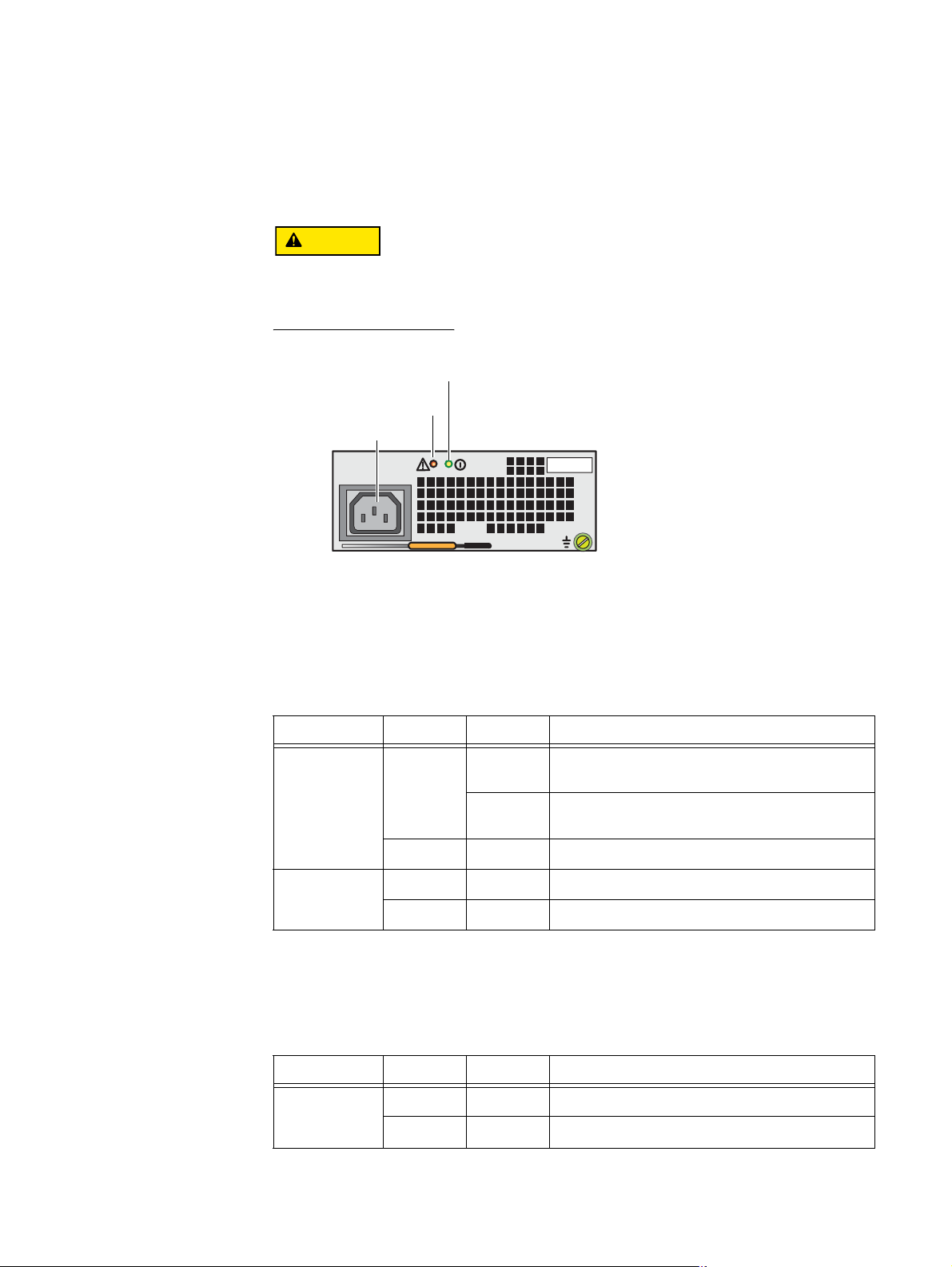
SP AC power supply
Figure 17 shows an example of the SP AC power supply/cooling module with a power in
(recessed) connector (plug) and status LEDs. The SP is cooled by this power supply on
top.
Do not
remove the SP power supply/cooling module while the SP is plugged in. Power
supply module removal for more than a few minutes can cause the SP to shut down due
to lack of cooling.
Power on LED
Power fault LED
Power supply in
VNX-000108
Figure 17 SP AC power supply module power in (recessed) connector (plug) and status LEDs
Table 11 describes the power supply module (fault and power on) LEDs.
Table 11 SP AC power supply/cooling module (fault and power on) LEDs
Led Color State Description
Fault Amber On Power supply or backup fault, check cable
Blinking BIOS, POST and OS booting up or system
— Off No fault or power off
Power Green On Power on
— Off Power off, verify source power
connection
overheating
Table 12 describes the SP LEDs. The locations in Table 12 are shown in Figure 16 on
page 26.
Table 12 SP LEDs
Led Color State Description
Unsafe to
remove
(location 10)
White On
— Off Safe to remove SP
Do not
remove SP
EMC VNX5300 Hardware Information Guide 27
Page 28
System component description
Table 12 SP LEDs (continued)
Led Color State Description
Fault
Amber On Fault
(location 11)
— Off No fault or power off
Power
Green On Power on
(location 12)
— Off Power off, verify connection
SP Input/output ports and connectors
The Block and File (Unified) VNX5300 platform SP supports the following I/O ports on the
rear:
◆ Two 6-Gb/s SAS PCI Gen 2 x4 ports (labeled 6Gb SAS 0 x4 and 1 x4); supported
speeds are 1.5, 3, and 6 Gb/s
◆ Four 8-Gb/s Fibre Channel (FC) ports (for front-end connectivity)
◆ One Ethernet (RJ-45) 10/100/1000 LAN (management) port
◆ One Ethernet (RJ-45) 10/100/1000 LAN (service laptop) port
◆ One RS-232/EIA 232 (micro DB-9) SPS connector
◆ One RS-232/EIA 232 (micro DB-9) service laptop connector
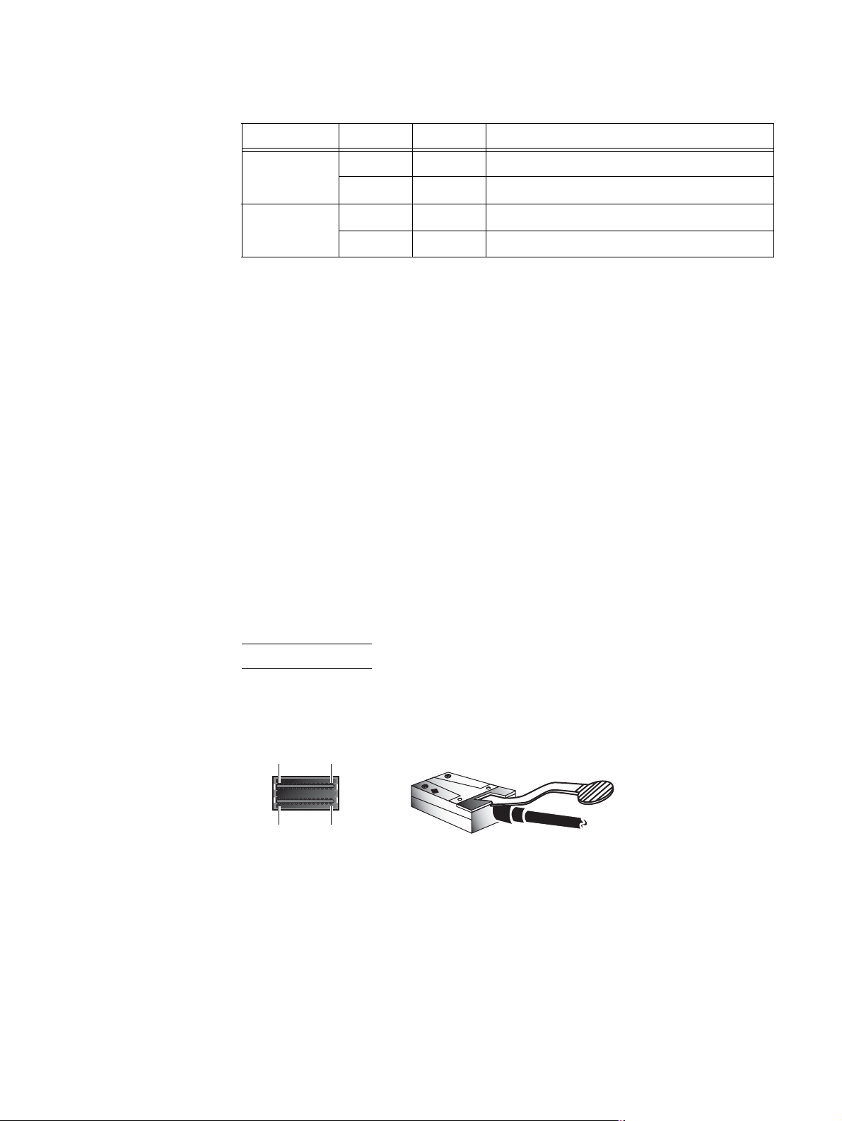
6-Gb/s SAS x4 ports — The Block and File (Unified) VNX5300 platform SP supports two
6-Gb/s SAS x4 ports (labeled 6Gb SAS 0 x4 and 6Gb SAS 1 x4) on the rear of each SP (A
and B). These ports provide an interface for SAS and NL-SAS drives on the DAE. This port
is a 26-circuit SAS small form-factor 8088 (SFF-8088) specification (socket or receptacle)
using an SFF-8088 specification mini-SAS 26-circuit cable (plug) with a pull tab.
Note: Each SAS cable is keyed with an in and
out
connection to prevent incorrect cabling.
Figure 18 shows an example of the port connector (socket) and cable connector (plug)
with pull tab.
Pin A1 A13
B1 B13
VNX-000094
Figure 18 SP 6-Gb/s SAS port and cable connector
28 EMC VNX5300 Hardware Information Guide
Page 29
System component description
Table 13 lists the SP 6-Gb/s SAS port pin signals used on the connector.
Table 13 SP 6-Gb/s SAS port connector pinout
Pin Signal Pin Signal
A1 GND B1 GND
A2 Rx 0+ B2 Tx 0+
A3 Rx 0- B3 Tx 0-
A4 GND B4 GND
A5 Rx 1+ B5 Tx 1+
A6 Rx 1- B6 Tx 1-
A7 GND B7 GND
A8 Rx 2+ B8 Tx 2+
A9 Rx 2- B9 Tx 2-
A10 GND B10 GND
A11 Rx 3+ B11 Tx 3+
A12 Rx 3- B12 Tx 3-
A13 GND B13 GND
SP 6-Gb/s SAS port LEDs — Figure 19 shows an example of the SP 6-Gb/s SAS 0 x4 port
LED—a bi-color (blue/green) LED to the right of the connector—that indicates the
link/activity of the SAS port.
6Gb SAS
0 X4
0 x 4
Figure 19 Example of the SP 6-Gb/s SAS 0 x4 port LED
VNX-000102
Table 14 describes the SP 6-Gb/s port LEDs.
Table 14 SP 6-Gb/s SAS port LEDs
LED Color State Description
Link/activity Blue On All lanes are running at 6 GB/s
Green On One or more lanes is not running at full speed or
disconnected
Alternating
Blue/Green
—OffNot connected
Blinking Port is being marked by the host
EMC VNX5300 Hardware Information Guide 29
Page 30
System component description
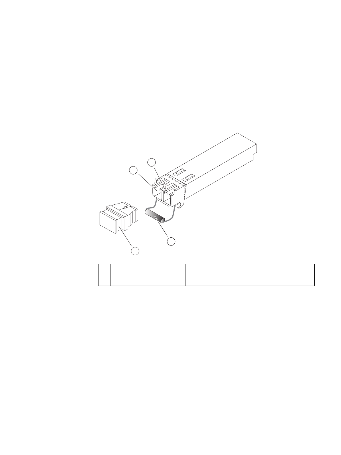
8-Gb/s FC ports
The Block and File (Unified) VNX5300 platform SP comes with four optical (fibre) 8-Gb/s
Fibre Channel (FC) ports (labeled 8GB fibre 2, 3, 4, and 5) on the rear of each SP (A and B).
These ports provide an optical interface for connecting to the front end. These ports
support 2-, 4-, and 8-Gb/s Fibre Channels using a small form-factor pluggable (SFP+)
transceiver module. The SFP+ transceiver modules connect to Lucent Connector (LC) type
optical fibre cables. These SFP+ transceiver modules are input/output (I/O) devices.
These SFP+ modules are hot swappable. This means that you can install and remove an
SFP+ module while the SP is operating. Figure 20 shows an example of an SFP+ module.
4
3
2
1
1 Dust plug (protective cap) 3 Send or transmit (TX) optical bore
2 Bale clasp latch 4 Receive (RX) optical bore
Figure 20 Example of an SFP+ module
The LC type interface was developed by Lucent Technologies (hence, Lucent Connector). It
uses a push-pull mechanism. LC connectors are normally held together in a multimode
duplex configuration with a plastic clip. These cables are usually colored orange for OM2
multimode optical fiber type cables and aqua for OM3 multimode optical fiber type
cables. These cables have the duplex connectors encased in a gray plastic covering. To
determine the send or transmit (TX) and receive (RX) ferrules (connector ends), these
cables will show a letter and numeral (for example A1 and A2 for the TX and RX,
respectively) or a white and yellow rubber gasket (jacket) for the send or transmit (TX) and
receive (RX) ends (Figure 21 on page 31).
CNS-001090
30 EMC VNX5300 Hardware Information Guide
Page 31

System component description
A
2
A
1
1
3
2
4
1 Orange cable 3 Rubber gasket (jacket), receive (RX)
2 Rubber gasket (jacket), send or
transmit (TX)
Figure 21 Example of LC-type connectors
4 Ferrule (connector end to SFP+ module)
CNS-001102
Figure 22 shows an example of the SP 8-Gb/s FC connector with an SFP+ in slots 2 and 3.
8Gb
bre
2
Figure 22 Example of SP 8-Gb/s FC connector with an SFP+ in slots 2 and 3
3
4
Table 15 describes the SP 8-Gb/s FC port LEDs.
Table 15 8-Gb/s FC port LEDs
Led Color State Description
Link/Activity
(each port has
one LED)
Green On 2- or 4-Gb/s link speed (suboptimal speed)
Blue On 8-Gb/s link speed (maximum speed)
Green or
Blue
Blinking Small form-factor pluggable (SFP+
5
VNX-000284
1
) transceiver
module faulted, unsupported, or optical cable fault.
1. Refer to the
— Off No network connection
VNX5300 Parts Location Guide
for part number label location for the SFP+ part number.
EMC VNX5300 Hardware Information Guide 31
Page 32

System component description
IMPORTANT
Network management and service laptop Ethernet (RJ-45) ports
The SP Ethernet (RJ-45) ports are LAN ports not WAN ports. LAN ports contain safety
extra-low voltage (SELV) circuits, and WAN ports contain telephone-network voltage (TNV)
circuits. Some LAN and WAN ports both use RJ-45 connectors. Use caution when
connecting cables. To avoid electric shock, do not connect TNV circuits to SELV circuits.
The Block and File (Unified) VNX5300 platform SP comes with two integrated dual-port
Ethernet ports (labeled with a network management symbol and a wrench symbol,
respectively). These ports provide an interface for connecting to the public LAN and a
service laptop computer, respectively. The ports are 8-pin MDI RJ-45 type ports for either
IEEE 802.3 10BASE-T (10 Mb/s), IEEE 802.3u 100BASE-TX (100 Mb/s), or 1000BASE-T
(1000 Mb/s) Ethernet connections.
Figure 23 shows an example of the SP network management and service laptop Ethernet
(RJ-45) ports.
VNX-000095
Figure 23 Network management and service laptop Ethernet (RJ-45) ports
The ports shown in Figure 23 are LAN ports. A symbol depicting a telephone handset with
a line through it indicates that you should not connect WAN type RJ-45 telephone
connectors to these ports.
To access the Ethernet ports, connect a Category 3, 4, 5, 5E, or 6 unshielded twisted-pair
(UTP) cable to the RJ-45 connectors on the back of the SP, as described in Table 16.
Table 16 Ethernet cabling guidelines
Type Description
10BASE-T EIA Categories 3, 4, or 5 UTP (2 or 4 pairs) up to 328 ft (100 m)
100BASE-TX EIA Category 5 UTP (2 pairs) up to 328 ft (100 m)
1000BASE-T EIA Category 6, up to 1,804 ft (550 m), Category 5E UTP (2 pairs) up to
10GBASE-T EIA Category 7 STP, backwards compatible with Cat 5 and 6, from 2,296.5
1,148 ft (350 m)
to 3,280.8 ft (700 to 1000 m)
32 EMC VNX5300 Hardware Information Guide
Page 33

System component description
Network management and service laptop Ethernet (RJ-45) port and connector
(adapter) — Figure 24 shows an example of the Ethernet (RJ-45) port and cable connector.
1 2 3 4 5 6 7 8
VNX-000111
Figure 24 Network management and service laptop Ethernet (RJ-45) port and connector (adapter)
Table 17 lists the SP network management and service laptop Ethernet (RJ-45) pin signals
used on the connector.
Table 17 Network management and service laptop Ethernet (RJ-45) port and connector pinout
RJ-45 pin Signal Description
1 BI_DA+ Bi-directional pair A +
2 BI_DA- Bi-directional pair A -
3 BI_DB+ Bi-directional pair B +
4 BI_DC+ Bi-directional pair C +
5 BI_DC- Bi-directional pair C -
6 BI_DB- Bi-directional pair B -
7 BI_DD+ Bi-directional pair D +
8 BI_DD- Bi-directional pair D -
Network management and service laptop Ethernet (RJ-45) port LEDs — Figure 25 shows
the SP Ethernet (RJ-45) port LEDs—a green LED to the left of the connector and a bi-color
(green/amber) LED to the right of the connector—that indicate the link/activity and speed
of the Ethernet ports, respectively.
12
VNX-000110
Figure 25 Network management and service laptop Ethernet (RJ-45) port LEDs
EMC VNX5300 Hardware Information Guide 33
Page 34

System component description
Table 18 describes the link/activity and connection speed associated with the SP
Ethernet (RJ-45) port LEDs.
Table 18 Network management and service laptop Ethernet (RJ-45) port LEDs
Led Color State Description
Left, link
(location 1)
Right, link
speed
(location 2)
Green On Network/link connection
Green Blinking Transmit/receive activity
— Off No network/link connection
Green On 100-Mb/s connection
Amber On 1000-Mb/s (or 1-Gb/s) connection
— Off 10-Mb/s connection (if left LED is on or blinking)
Serial RS-232/EIA 232 (micro DB-9) socket connector
The back of the Block and File (Unified) VNX5300 platform SP includes a standard serial
Electronics Industries Association (EIA) RS-232 interface (micro DB-9) connector (labeled
with a symbol depicting a wrench on the upper left) to connect to a PC or service laptop
computer. This serial connector (port) allows you to access the SP locally by connecting a
terminal—either a PC running terminal-emulation software or an ASCII terminal—to the
port.
Notice the orientation of the pins shown in Figure 26.
Pin 1
5
6
Figure 26 Serial RS-232/EIA 232 (micro DB-9) connector (socket) for service laptop
Table 19 lists the SP serial RS-232/EIA 232 (micro DB-9) pin signals used on the
connector.
Table 19 Serial RS-232/EIA 232 (micro DB-9) connector (socket) pinout
DB-9 Pin Signal Description
1 CD Carrier detect
2RXDReceived data
3 TXD Transmitted data
4 DTR Data terminal ready
5GNDGround
6DSRData set ready
34 EMC VNX5300 Hardware Information Guide
9
VNX-000079
Page 35

System component description
Table 19 Serial RS-232/EIA 232 (micro DB-9) connector (socket) pinout (continued)
DB-9 Pin Signal Description
7 RTS Request to send
8 CTS Clear to send
9 RI Ring indicator
SP null modem (micro DB-9 to DB-9 serial) cable
The cable connecting the SP to the PC or service laptop is a micro DB-9 cable (plug) to
serial DB-9 (socket). It has a micro DB-9 plug (SP side) on one end and a serial DB-9
socket (PC or service laptop side) on the other end. Figure 27 shows an example of an SP
to PC (service laptop) cable.
VNX-000093
Figure 27 Example of SP null modem (micro DB-9) to serial (DB-9) cable
Serial RS-232/EIA 232 (micro DB-9) connector (socket) for SPS
management
The back of the Block and File (Unified) VNX5300 platform SP includes a second standard
serial RS-232/EIA 232 interface (micro DB-9) socket connector (labeled with a symbol
depicting a battery to the left) to connect to the SPS management port (RJ-12). Notice the
orientation of the pins shown in Figure 28.
Note: The included cable has a micro DB-9 connector (pins 1, 3, and 4 are used) on one
end and an RJ-12 modular jack adapter (pins 1, 7, and 8 are used) on the other end. The
RJ-12 modular jack adaptor end connects to the RJ-12 modular jack connector on the SPS
(Figure 14 on page 24).
Pin 1
5
69
VNX-000105
Figure 28 Serial RS-232/EIA 232 (micro DB-9) connector (socket)
EMC VNX5300 Hardware Information Guide 35
Page 36

System component description
Table 20 lists the SP serial RS-232/EIA 232 (micro DB-9) pin signals used on the
connector.
Table 20 Serial RS-232/EIA 232 (micro DB-9) connector (socket) pinout
DB-9 Pin Signal Description
1 CD Carrier detect
2 RXD Received data
3 TXD Transmitted data
4 DTR Data terminal ready
5GNDGround
6DSRData set ready
7 RTS Clear to send
8 CTS Request to send
9 RI Ring indicator
SP I/O module slots
Two SP PCI Gen 2 x4 I/O module slots are available. These slots support the following I/O
modules (Figure 29):
◆ Two-port 10-Gb/s optical or active Twinax (w/iSCSI protocol)
◆ Four-port 1-Gb/s copper iSCSI
◆ Four-port 8-Gb/s optical Fibre Channel (running at 2, 4, or 8-Gb/s)
◆ Two-port 10-Gb/s optical or active Twinax Fibre Channel over Ethernet (FCoE)
SP I/O Module Slots
PART NUMBER
REV A09 A
8Gb
6Gb
bre
SAS
5
2
4
3
PART NUMBER
REV A09 A
123
0
1
X4
0123
Figure 29 Example of SP with a Fibre Channel (FC) I/O module and an iSCSI I/O module
36 EMC VNX5300 Hardware Information Guide
0 X4
6Gb SAS
VNX-000569
Page 37

Control Station rear view
System component description
For a full description of the I/O module types used in the SP, go to“I/O modules” on
page 46.
On the rear, viewing from left to right, the Block and File (Unified) VNX5300 platform 1U
Control Station includes the following hardware components:
◆ AC power in connector
◆ Two PS/2 connectors (keyboard and mouse)—not used
◆ One (DB-9 plug) serial modem connector
◆ One (DB-15) video (VGA socket) connector—not used
◆ Four (RJ-45) NIC (labeled A, CS, B, and MGMT) connectors
Note: The RJ-45 NICs (labeled A and CS) are integrated into the rear of the 1U Control
Station while the RJ-45 NICs (labeled B and MGMT) are on a PCI-e card in the
expansion slot on the rear of the 1U Control Station.
◆ One (DB-9 plug) serial console (RS-232/EIA-232) connector
◆ Two USB 2.0 connectors—not used
◆ POST diagnostic LEDs
◆ Two CAT-5E/6 panel-mount Ethernet cable extensions
EMC VNX5300 Hardware Information Guide 37
Page 38

System component description
Figure 30 shows the orientation of these components.
1
2 3 4 5 6 7
12
11
CS
A
8910
B
MGMT
CNS-001741
1 AC power in connector 7 DB-9 serial console plug connector
2 PS/2 connector (mouse)—not used 8 Two USB 2.0 connectors—not used
3 DB-9 serial modem plug connector 9 RJ-45 Ethernet NIC port (labeled A)
4 RJ-45 Ethernet NIC port (labeled CS
5 RJ-45 Ethernet NIC port (labeled B)
1
)
3
10 POST diagnostic LEDs
11 DB-15 Video (VGA) socket connector—not
2
used
6 RJ-45 Ethernet NIC port (labeled MGMT)
1. The CS port uses an IPMI (Intelligent Platform Management Interface) cable to connect to a standby Control
Station.
2. These LEDs might light during power on self test (POST); they are not important for the administration or
maintenance of the Control Station.
3. An extension cable with a label (CS 0 B) is provided with this connector (see the cable kit).
4. An extension cable with a label (CS 0 MGMT) is provided with this connector (see the cable kit).
4
12 PS/2 connector (keyboard)—not used
Figure 30 VNX5300 platform Control Station (rear view)
Control Station Input/output ports and connectors
The Block and File (Unified) VNX5300 platform 1U Control Station supports the following I/O
ports on the rear of the 1U Control Station:
◆ Four Ethernet (RJ-45) NIC ports
◆ One serial modem (DB-9) plug connector
◆ One serial console (DB-9) plug connector
To avoid electric shock, do not connect safety extra-low voltage (SELV) circuits to
telephone-network voltage (TNV) circuits. LAN ports contain SELV circuits, and WAN ports
contain TNV circuits. Some LAN and WAN ports both use RJ-45 connectors. Use caution
when connecting cables.
Control Station Ethernet (RJ-45) NIC ports
The Block and File (Unified) VNX5300 platform 1U Control Station comes with two
integrated dual-port Ethernet ports (labeled A and CS) and two Peripheral Component
Interconnect Express (PCI-E)
MGMT) in an expansion slot on the rear of the Control Station. These ports provide an
6
low profile card dual-port Ethernet ports (labeled B and
38 EMC VNX5300 Hardware Information Guide
Page 39

System component description
interface for connecting to 10-Mb/s, 100-Mb/s, or 1000-Mb/s networks and provide
full-duplex (FDX) capability, which enables simultaneous transmission and reception of
data on the Ethernet local-area network (LAN).
To access the Ethernet ports, connect a Category 3, 4, 5, 5E, or 6 unshielded twisted-pair
(UTP) cable to the RJ-45 connectors on the back of the Control Station, as described in
Table 21.
Table 21 Ethernet cabling guidelines
Type Description
10BASE-T EIA Categories 3, 4, or 5 UTP (2 or 4 pairs) up to 328 ft (100 m)
100BASE-TX EIA Category 5 UTP (2 pairs) up to 328 ft (100 m)
1000BASE-T EIA Category 6, up to 1,804 ft (550 m), Category 5E UTP (2 pairs) up to
1,148 ft (350 m)
10GBASE-T EIA Category 7 STP, backwards compatible with Cat 5 and 6, from 2,296.5
to 3,280.8 ft (700 to 1000 m)
Control Station Ethernet (RJ-45) port and connector (adapter)
Figure 31 shows an example of the Ethernet RJ-45 port and cable connector.
8 7 6 5 4 3 2 1
Figure 31 Control Station Ethernet (RJ-45) port and connector (adapter)
CNS-001749
Table 22 lists the Control Station Ethernet (RJ-45) pin signals used on the connector.
Table 22 Control Station Ethernet (RJ-45) port and connector pinout
RJ-45 pin Signal Description
1 BI_DA+ Bidirectional pair A, +
2 BI_DA- Bidirectional pair A, -
3 BI_DB+ Bidirectional pair B, +
4 BI_DC+ Bidirectional pair C, +
5 BI_DC- Bidirectional pair C, -
6. PCI Express is used in consumer, server, and industrial applications, as a motherboard-level
interconnect (to link motherboard-mounted peripherals) and as an expansion card interface for
add-in boards.
EMC VNX5300 Hardware Information Guide 39
Page 40

System component description
Table 22 Control Station Ethernet (RJ-45) port and connector pinout (continued)
RJ-45 pin Signal Description
6 BI_DB- Bidirectional pair B, -
7 BI_DD+ Bidirectional pair D, +
8 BI_DD- Bidirectional pair D, -
Control Station Ethernet (RJ-45) port LEDs
The 1U Control Station (RJ-45) NICs include LEDs—a green LED to the left of the connector
and a bi-color (green/amber) LED to the right of the connector—that indicate the
link/activity and speed of the 1U Control Station (RJ-45) NIC ports, respectively
(Figure 32).
Table 23 describes the link/activity and connection speed associated with the 1U Control
Station (RJ-45) port LEDs.
1 2
CNS-001748
Figure 32 Control Station Ethernet (RJ-45) port LEDs
Table 23 Control Station RJ-45 port LEDs
Led Color State Description
Left,
link/activity
(location 1)
Right, link
speed
(location 2)
Green On Network/link connection
Green Blinking Transmit/receive activity
— Off No network/link connection
Green On 100-Mb/s connection
Amber On 1000-Mb/s (or 1-Gb/s) connection
— Off 10-Mb/s connection (if left LED is on or blinking)
Ethernet cable extensions for the Control Station B and MGMT ports
Each Block and File (Unified) VNX5300 platform 1U Control Station (CS 0) comes with two
modular Ethernet cable extensions (or patch cords) for the RJ-45 ports (labeled on the CS
as B and MGMT, respectively). These cables allow you to extend the length of the Ethernet
cables from the CS 0, port B to Data Mover Enclosure 0, management module B, port 1
and CS 0, MGMT port to the public LAN. Each cable includes a corresponding label wrap to
assist you during system cabling (Figure 33 on page 41).
40 EMC VNX5300 Hardware Information Guide
Page 41

System component description
If your Block and File (Unified) VNX5300 platform includes a second optional 1U Control
Station (CS 1), another set of Ethernet cable extensions for the RJ-45 ports is provided.
These cables allow you to extend the length of the Ethernet cables from the CS 1, port B to
Data Mover Enclosure 0, management module B, port 2 and CS 1, MGMT port to the public
LAN. Each cable includes a corresponding label clip to assist you during system cabling.
Note: If you received the Block and File (Unified) VNX5300 platform already installed in a
cabinet rack with all of the Block and File (Unified) VNX5300 platform components, all the
cabling has already been installed.
VNX-000564
Figure 33 Example of Ethernet extension (modular plug to modular jack) cable
Control Station serial console (DB-9) plug connector
The back of the Block and File (Unified) VNX5300 platform 1U Control Station includes a
standard serial console Electronics Industries Association (EIA) RS-232 interface (DB-9)
plug connector (labeled with a symbol depicting a wrench on the right). Notice the
orientation of the pins (Figure 34).
Pin 1
6
Figure 34 Control Station serial console (DB-9) plug connector
5
9
CNS-001742
Table 24 lists the Control Station Ethernet (DB-9) pin signals used on the connector.
Table 24 Control Station (DB-9) plug connector pinout
DB-9 Pin Signal Description
1 CD Carrier detect
2RXDReceived data
3 TXD Transmitted data
4 DTR Data terminal ready
5GNDGround
6DSRData set ready
7 RTS Request to send
8 CTS Clear to send
9 RI Ring indicator (not used)
EMC VNX5300 Hardware Information Guide 41
Page 42

System component description
Control Station modem (DB-9) plug connector
The back of the Block and File (Unified) VNX5300 platform 1U Control Station includes a
standard modem serial interface (DB-9) plug connector (labeled with a symbol depicting a
telephone handset on the left). Notice the orientation of the pins (Figure 35).
Pin 1
Figure 35 Control Station modem (DB-9) plug connector
5
6
9
CNS-001750
Table 25 lists the 1U Control Station Ethernet (DB-9) pin signals used on the connector.
Table 25 Control Station modem (DB-9) plug connector pinout
DB-9 Pin Signal Description
1 CD Carrier detect
2 RXD Received data
3 TXD Transmitted data
4 DTR Data terminal ready
5GNDGround
6DSRData set ready
7 RTS Clear to send
8 CTS Request to send
DME rear view
9 RI Ring indicator (not used)
The rear of the Block and File (Unified) VNX5300 platform 2U DME does not contain any
LEDs (Figure 36). Only the Data Mover management module and the I/O modules have
LEDs.
Note: Figure 36 is a graphical representation of a Block and File (Unified) VNX5300
platform 2U DME rear view with two Data Movers (each Data Mover has one management
module, one four-port 8-Gb/s FC I/O module, thee two-port 1-Gb/s plus two-port 1-Gb/s
optical I/O modules, and one filler panel module).
42 EMC VNX5300 Hardware Information Guide
Page 43

System component description
0
12 3
235 4
23
1
0
1
CNS-001767
123
0
23
1
0
12 3
0
12 3
0
23
1
0
123
0
12 3
0
12 3
0
1 DME 4 Four-port 8-Gb/s FC I/O module
2 Filler panel module 5 Data Mover management module
3 Two-port 1-Gb/s copper plus two-port
1-Gb/s optical I/O module
Figure 36 DME (rear view)
Data Mover management module
The Data Mover management module provides the management connections via three
10/100/1000 Ethernet (RJ-45) ports. The Data Mover management module also includes
one RS-232 (EIA) DB-9 serial socket connector for service laptop connection and several
LEDs (Figure 37).
1
2
7
2
1
6
0
5
#
3
4
CNS-001754
1 Power/fault LED 5 DB-9 serial console socket connector
2 Data Mover management module push
6 RJ-45 Ethernet NIC port (labeled 0)
button latch handle
3 RJ-45 Ethernet NIC port (labeled 1) 7 RJ-45 Ethernet NIC port (labeled 2)
4 DME ID numeric display
Figure 37 Data Mover management module
EMC VNX5300 Hardware Information Guide 43
Page 44

System component description
Data Mover management module Ethernet (RJ-45) NIC ports
The Block and File VNX5300 platform Data Mover management module comes with three
integrated dual-port Ethernet ports (labeled 0, 1, and 2) on the rear of the Data Mover
management module. These ports support an interface for connecting to 10-Mb/s,
100-Mb/s, or 1000-Mb/s networks and provide full-duplex (FDX) capability, which
enables simultaneous transmission and reception of data.
To avoid electric shock, do not connect safety extra-low voltage (SELV) circuits to
telephone-network voltage (TNV) circuits. LAN ports contain SELV circuits, and WAN ports
contain TNV circuits. Some LAN and WAN ports both use RJ-45 connectors. Use caution
when connecting cables.
To access the Ethernet ports, connect a Category 3, 4, 5, 5E, or 6 unshielded twisted-pair
(UTP) cable to the RJ-45 connector on the back of the Data Mover management module, as
described in Table 16 on page 32.
Since the Control Station and the Data Mover management module have the same type of
RJ-45 NIC ports, “Control Station Ethernet (RJ-45) NIC ports” on page 38 provides detailed
information about the Data Mover management module NIC ports.
Data Mover management module LEDs
Figure 38 shows the LEDs and Table 26 describes them.
Power/Fault LED
Port 2 (Activity LED)
2
Port 2 (Link LED)
Port 0 (Link LED)
Port 0 (Activity LED)
Figure 38 Data Mover management module LEDs
0
#
Port 1 (Activity LED)
1
Port 1 (Link LED)
Numeric display
(DME ID)
CNS-001671
44 EMC VNX5300 Hardware Information Guide
Page 45

System component description
Table 26 Data Mover management module LEDs
LED Color State Description
Power/Fault Green On Data Mover management module is powered up.
Amber On Data Mover management module has faulted.
Note: LED is always illuminated at powerup, until it is
initialized.
— Off Data Mover management module is powered down.
Link (each
Green On Network connection
port has one)
— Off No network connection
Activity (each
Amber Blinking Transmit/receive activity
port has one)
— Off No network activity
numeric
(7-segment)
— On Displays the enclosure ID assigned to the Data Mover
Enclosure.
display for
enclosure ID
Note: Each enclosure is assigned a number at installation.
Data Mover management module serial console (DB-9) socket connector
The back of the Block and File (Unified) VNX5300 platform Data Mover management
module includes a standard serial console Electronics Industries Association (EIA) RS-232
interface (DB-9) socket connector (labeled with a wrench tool icon on the left). Notice the
orientation of the pins (Figure 39).
5
9
6
Pin 1
CNS-001753
Figure 39 Data Mover management module serial console (DB-9) socket connector
Table 27 lists the Data Mover management module Ethernet (DB-9) pin signals used on
the connector.
Table 27 Data Mover management module (DB-9) socket connector pinout
DB-9 Pin Signal Description
1 CD Carrier detect
2 TXD Transmitted data
3 RXD Received data
4 DTR Data terminal ready
EMC VNX5300 Hardware Information Guide 45
Page 46

I/O modules
IMPORTANT
I/O modules
Table 27 Data Mover management module (DB-9) socket connector pinout (continued)
DB-9 Pin Signal Description
5GNDGround
6DSRData set ready
7 RTS Clear to send
8 CTS Request to send
9 RI Ring indicator (not used)
Several types of I/O modules are supported in the Block and File (Unified) VNX5300
platform. The SP supports five types of I/O modules (see the “SP I/O module types”
section on page 46) and the Data Mover supports five types of I/O modules (see the “Data
Mover I/O module types” section on page 56). In each of these sections, an I/O module
description is included with the type of port (copper, optical, or other) as well as a
description of the LEDs on the I/O module.
When adding new I/O modules, always install I/O modules in pairs—one module in SP A
and one module in SP B. Both SPs must have the same type of I/O modules in the same
slots. For more information, refer to the
document.
SP I/O module types
The following I/O module types are supported in the Block and File (Unified) VNX5300
platform SP:
◆ “Four-port 8-Gb/s FC I/O module” on this page
◆ “Four-port 1-Gb/s copper iSCSI I/O module” on page 48
◆ “Two-port 10-Gb/s optical or active Twinax iSCSI I/O module” on page 50
◆ “Two-port 10-Gb/s optical or active Twinax Fibre Channel over Ethernet (FCoE) I/O
module” on page 52
◆ “Two-port 10-Gb/s RJ-45 Base-T iSCSI/IP I/O module” on page 54
Four-port 8-Gb/s FC I/O module
The four-port 8-Gb/s FC I/O module (labeled 8 GbE Fibre on the latch handle) comes with
four optical (fibre) ports, one power/fault LED, and a link/activity LED for each optical port
(Figure 40 on page 47). This I/O module can interface at speeds of 2, 4, and 8 Gb/s.
Besides optical SFP or SFP+, it uses OM2/OM3 multimode optical fiber type cabling to
connect directly to a host HBA or FC switch. OM2 cabling can usually be distinguished by
the orange color of the cable. While, OM3 cabling can be distinguished by the aqua color
of the cable.
Adding I/O modules and SFPs to the DPE
46 EMC VNX5300 Hardware Information Guide
Page 47

I/O modules
1
2
3
4
CNS-001752
1 Push button latch handle 3 SFP+ (optical) port (four)
2 Power/fault LED 4 SFP+ link/activity LED
Figure 40 Four-port 8-Gb/s FC I/O module
The four-port 8-Gb/s FC I/O module uses SFP+ transceiver modules to connect to LC-type
optical fibre cables. These SFP+ transceiver modules are input/output (I/O) devices that
plug into the FC port of the FC I/O modules. These SFP+ modules are hot swappable.
This means that you can install and remove an SFP+ module while the Block and File
(Unified) VNX5300 platform is operating.
Note: The Lucent Connector (LC) type interface was developed by Lucent Technologies
(hence, Lucent Connector). It uses a push-pull mechanism. LC connectors are normally
held together in a multimode duplex configuration with a plastic clip. These cables are
usually colored orange for OM2 type cables and aqua for OM3 type cables. These cables
have the duplex connectors encased in a gray plastic covering. To determine the send or
transmit (TX) and receive (RX) ferrules (connector ends), these cables will show a letter
and numeral (for example A1 and A2 for the TX and RX, respectively) or a white and yellow
rubber gasket (jacket) for the send or transmit (TX) and receive (RX) ends.
EMC VNX5300 Hardware Information Guide 47
Page 48

I/O modules
Four-port 8-Gb/s FC I/O module LEDs
The four-port 8-Gb/s Fibre Channel (FC) I/O module has two different types of status LEDs.
Figure 41 shows the LEDs and Table 28 describes them.
Power/fault
LED
Link/Activity
LED
Link/Activity
LED
Link/Activity
LED
Link/Activity
LED
CNS-001670
Figure 41 Four-port 8-Gb/s FC I/O module LEDs
Table 28 Four-port 8-Gb/s FC I/O module LEDs
LED Color State Description
Power/Fault Green On I/O module is powered up.
Amber On I/O module has faulted.
— Off I/O module is powered down.
Link/Activity
(each port
has one
LED)
1. Refer to the
Green On 2- or 4-Gb link speed (suboptimal speed)
Blue On 8-Gb/s link speed (maximum speed)
Green or
Blue
— Off No network connection
VNX5300 Parts Location Guide
Four-port 1-Gb/s copper iSCSI I/O module
The four-port 1-Gb/s copper iSCSI I/O module with IPv6 (labeled 1 GbE iSCSI/TOE on the
latch handle) comes with four 1 Gb/s Ethernet Base-T copper ports, one power/fault LED,
and a link and activity LED for each copper port (Figure 42). This iSCSI I/O module can
interface at speeds of 1 Gb/s. The 1 Gb/s Ethernet Base-T copper ports connect to Cat 6
cabling (see Table 16, “Ethernet cabling guidelines,” on page 32 or Table 21, “Ethernet
cabling guidelines,” on page 39) to an Ethernet switch. This I/O module also includes a
TCP offload engine (or TOE).
Blinking Small form-factor pluggable (SFP+
faulted, unsupported, or optical cable fault.
for the part number label location for the SFP+ part number.
1
) transceiver module
48 EMC VNX5300 Hardware Information Guide
Page 49

1 2
3
4
5
CNS-001751
1 Push button latch handle 4 RJ-45 NIC link LED
2 Power/fault LED 5 RJ-45 NIC activity LED
I/O modules
3 RJ-45 NIC (copper) port (four)
Figure 42 Four-port 1-Gb/s copper iSCSI I/O module
EMC VNX5300 Hardware Information Guide 49
Page 50

I/O modules
Four-port 1-Gb/s copper iSCSI I/O module LEDs
The four-port 1-Gb/s copper iSCSI I/O module has three types of status LEDs. Figure 43
shows the LEDs and Table 29 on page 50 describes them.
Power/fault
LED
Link LEDs
Figure 43 Four-port 1-Gb/s copper iSCSI I/O module LEDs
Table 29 Four-port 1-Gb/s copper iSCSI I/O module LEDs
LED Color State Description
Power/Fault Green On I/O module is powered up.
Amber On I/O module has faulted.
— Off I/O module is powered down.
Link (each
port has
one)
Activity
(each port
has one)
Green On Network connection
— Off No network connection
Amber Blinking Transmit/receive activity
— Off No activity
Activity LEDs
CNS-001666
Two-port 10-Gb/s optical or active Twinax iSCSI I/O module
The two-port 10-Gb/s optical or active Twinax7 iSCSI I/O module (labeled 10 GbE iSCSI on
the latch handle) comes with two optical or active Twinax (twisted pair) copper ports, one
power/fault LED, and a link and activity LED for each port (Figure 44 on page 51). The
optical ports on this I/O module can interface at speeds of 10 Gb/s for iSCSI networks.
The two-port 10-Gb/s optical I/O module uses the SFP+ transceiver module (see the
section describing the SFP+ “Four-port 8-Gb/s FC I/O module” on page 46 for more
information about the SFP+ modules). The two-port 10-Gb/s optical I/O module uses
7. The two-port 10-Gb/s I/O module can also use active twinaxial (Twinax) cables. Twinax is a type of
cable similar to coax, but with two inner conductors instead of one. These cables will be supplied
in lieu of the SFP+ when so ordered.
50 EMC VNX5300 Hardware Information Guide
Page 51

I/O modules
iSCSI protocol, hence the required SFP+ transceiver module uses a different part number
(for part number label location, see the
VNX5300 Parts Location Guide
). This I/O module
also includes a TCP offload engine (or TOE).
1
2
3
1
4
0
5
CNS-001756
1 Push button latch handle 4 SFP+ link LED (right)
2 Power/fault LED 5 SFP+ NIC activity LED (left)
3 SFP+ (optical) port (two)
Figure 44 Two-port 10-Gb/s optical I/O module
Two-port 10-Gb/s optical I/O module LEDs
The two-port 10-Gb/s optical I/O module has three types of status LEDs. Figure 45 shows
the LEDs and Table 30 on page 52 describes them.
Power/fault LED
1
Link LED
Activity LED
0
Link LED
Activity LED
CNS-001672
Figure 45 Two-port 10-Gb/s optical I/O module LEDs
EMC VNX5300 Hardware Information Guide 51
Page 52

I/O modules
Table 30 Two-port 10-Gb/s optical I/O module LEDs
LED Color State Description
Power/Fault Green On I/O module is powered up.
Amber On I/O module has faulted.
— Off I/O module is powered down.
Link Green On Network connection
— Off No network connection
Activity Amber Blinking Transmit/receive activity
— Off No activity
Two-port 10-Gb/s optical or active Twinax Fibre Channel over Ethernet (FCoE) I/O module
The two-port 10-Gb/s optical or active Twinax8 FCoE I/O module (labeled 10 GbE/FCoE on
the latch handle) comes with two FCoE ports, one power/fault LED, and a link and activity
LED for each port, as shown in Figure 46. The ports on this I/O module can interface at
speeds up to 10 Gb/s for Fibre Channel over Ethernet networks. The two-port 10-Gb/s
FCoE I/O module uses the SFP transceiver module. For part number label location, see the
VNX5300 Parts Location Guide
.
1
2
3
1
4
0
5
CNS-001756
1 Push button latch handle 4 SFP+ link LED (right)
2 Power/fault LED 5 SFP+ activity LED (left)
3 SFP+ (optical) port (two)
Figure 46 Two-port 10-Gb/s FCoE I/O module
8. The FCoE I/O module can also use active twinaxial (Twinax) cables. Twinax is a type of cable
similar to coax, but with two inner conductors instead of one. These cables will be supplied in lieu
of the SFP+ when so ordered.
52 EMC VNX5300 Hardware Information Guide
Page 53

I/O modules
Two-port 10-Gb/s FCoE I/O module LEDs
The two-port 10-Gb/s FCoE I/O module has three types of status LEDs. Figure 47 shows
the LEDs and Table 3 1 describes them.
Power/fault LED
1
Link LED
Activity LED
0
Link LED
Activity LED
CNS-001672
Figure 47 Two-port 10-Gb/s FCoE I/O module LEDs
Table 31 Two-port 10-Gb/s FCoE I/O module LEDs
LED Color State Description
Power/Fault Green On I/O module is powered up.
Amber On I/O module has faulted.
— Off I/O module is powered down.
Link Green On Network connection
— Off No network connection
Activity Amber Blinking Transmit/receive activity
— Off No activity
EMC VNX5300 Hardware Information Guide 53
Page 54

I/O modules
Two-port 10-Gb/s RJ-45 Base-T iSCSI/IP I/O module
The two-port 10-Gb/s RJ-45 Base-T iSCSI/IP I/O module (labeled 10GBase-T iSCSI on the
latch handle) comes with two 10-Gb/s Base-T copper ports, one power/fault LED, and a
link and activity LED for each port (Figure 48). The Base-T ports on this I/O module can
interface at speeds of 10 Gb/s for iSCSI networks. The two-port 10-Gb/s Base-T I/O
module uses EIA Category 6 or 6a Unshielded Twisted Pair (UTP) or EIA Category 7 fully
Shielded Twisted Pair (STP) copper cabling (see Table 16, “Ethernet cabling guidelines,”
on page 32 or Table 21, “Ethernet cabling guidelines,” on page 39).
1
10
2
3
4
5
VNXe-000751
1 Push button latch handle 4 Link LED (right)
2 Power/fault LED 7 Activity LED (left)
3 RJ-45 Base-T port (2)
Figure 48 Two-port 10-Gb/s RJ-45 Base-T I/O module
54 EMC VNX5300 Hardware Information Guide
Page 55

I/O modules
Two-port 10-Gb/s RJ-45 Base-T I/O module LEDs
The two-port 10-Gb/s RJ-45 Base-T I/O module has three types of status LEDs. Figure 49
shows the LEDs and Table 32 describes them.
Power/fault LED
10
VNXe-000752
Link LED
Activity LED
Link LED
Activity LED
Figure 49 Two-port 10-Gb/s RJ-45 Base-T I/O module LEDs
Table 32 Two-port 10-Gb/s RJ-45 Base-T I/O module LEDs
LED Color State Description
Power/Fault Green On I/O module is powered up.
Amber On I/O module has faulted.
— Off I/O module is powered down.
Link Green On Network connection
— Off No network connection
Activity Amber Blinking Transmit/receive activity
— Off No activity
EMC VNX5300 Hardware Information Guide 55
Page 56

I/O modules
Data Mover I/O module types
The following I/O module types are supported by the Block and File (Unified) VNX5300
platform Data Mover:
◆ “Four-port 8-Gb/s FC I/O module” on this page
◆ “Four-port 1-Gb/s copper I/O module” on page 58
◆ “Two-port 1-Gb/s copper plus two-port 1-Gb/s optical IP I/O module” on page 60
◆ “Two-port 10-Gb/s optical I/O module” on page 62
◆ “Two-port 10-Gb/s optical I/O module” on page 64
◆ “Two-port 10-Gb/s RJ-45 Base-T iSCSI/IP I/O module” on page 66
Note: For SP module types, go to “SP I/O module types” on page 46.
Four-port 8-Gb/s FC I/O module
The four-port 8-Gb/s FC I/O module (labeled 8 GbE Fibre on the latch handle) comes with
four optical (fibre) ports, one power/fault LED, and a link/activity LED for each optical port
(Figure 50). This I/O module can interface at speeds of 2, 4, and 8 Gb/s. Besides optical
SFP or SFP+, it uses OM2/OM3 multimode optical fiber type cabling to connect directly to
a host HBA or FC switch. OM2 cabling can usually be distinguished by the orange color of
the cable. While, OM3 cabling can be dis tin gui sed by the aqua color of the cable.
1
2
3
4
CNS-001752
1 Push button latch handle 3 SFP+ (optical) port (four)
2 Power/fault LED 4 SFP+ link/activity LED
Figure 50 Four-port 8-Gb/s FC I/O module
56 EMC VNX5300 Hardware Information Guide
Page 57

I/O modules
The four-port 8-Gb/s FC I/O module uses SFP+ transceiver modules to connect to LC-type
optical fibre cables. These SFP+ transceiver modules are input/output (I/O) devices that
plug into the FC port of the FC I/O modules. These SFP+ modules are hot swappable.
Be careful when replacing or swapping out SFP+ modules, your Data Mover will lose
access to the SP or tape drive to which it is connected
This means that you can install and remove an SFP+ module while the Block and File
(Unified) VNX5300 platform is operating.
Note: The Lucent Connector (LC) type interface was developed by Lucent Technologies
(hence, Lucent Connector). It uses a push-pull mechanism. LC connectors are normally
held together in a multimode duplex configuration with a plastic clip. These cables are
usually colored orange for OM2 type cables and aqua for OM3 type cables. These cables
have the duplex connectors encased in a gray plastic covering. To determine the send or
transmit (TX) and receive (RX) ferrules (connector ends), these cables will show a letter
and numeral (for example A1 and A2 for the TX and RX, respectively) or a white and yellow
rubber gasket (jacket) for the send or transmit (TX) and receive (RX) ends.
Four-port 8-Gb/s FC I/O module LEDs
The four-port 8-Gb/s Fibre Channel (FC) I/O module has two different types of status LEDs.
Figure 51 shows the LEDs and Table 33 describes them.
Power/fault
LED
Link/Activity
LED
Link/Activity
LED
Link/Activity
LED
Link/Activity
LED
CNS-001670
Figure 51 Four-port 8-Gb/s FC I/O module LEDs
Table 33 Four-port 8-Gb/s FC I/O module LEDs
LED Color State Description
Power/Fault Green On I/O module is powered up.
Amber On I/O module has faulted.
— Off I/O module is powered down.
EMC VNX5300 Hardware Information Guide 57
Page 58

I/O modules
Table 33 Four-port 8-Gb/s FC I/O module LEDs (continued)
LED Color State Description
Link/Activity
(each port
has one
LED)
1. Refer to the
Four-port 1-Gb/s copper I/O module
The four-port 1-Gb/s copper I/O module (labeled 1 GbE on the latch handle) comes with
four 10/100/1000 Base-T copper ports, one power/fault LED, and a link and activity LED
for each copper port (Figure 52). This I/O module can interface at speeds of 10 Mb/s,
100 Mb/s, and 1000 Mb/s (1 Gb/s). Another way to describe this type of module is that it
runs Ethernet over twisted pair. This I/O modules uses EIA Category 6 Unshielded Twisted
Pair (UTP) cabling to an Ethernet switch (see Table 16, “Ethernet cabling guidelines,” on
page 32 or Table 21, “Ethernet cabling guidelines,” on page 39).
Note: The four-port 1-Gb/s copper I/O module and the two-port 1-Gb/s copper plus
two-port 1-Gb/s optical IP I/O module (see “Two-port 1-Gb/s copper plus two-port 1-Gb/s
optical IP I/O module” on page 60) have the same 1 GbE label on the latch handle. The
only distinguishing difference between these I/O modules will be the SFP transceiver
modules used on ports 2 and 3.
Green On 2- or 4-Gb link speed (suboptimal speed)
Blue On 8-Gb/s link speed (maximum speed)
Green or
Blue
— Off No network connection
VNX5300 Parts Location Guide
Blinking Small form-factor pluggable (SFP+
faulted, unsupported, or optical cable fault.
for the correct SFP+ part number.
1
) transceiver module
1 2
3
4
5
CNS-001751
1 Push button latch handle 4 RJ-45 NIC link LED
2 Power/fault LED 5 RJ-45 NIC activity LED
3 RJ-45 NIC (copper) port (four)
Figure 52 Four-port 1-Gb/s copper I/O module
58 EMC VNX5300 Hardware Information Guide
Page 59

I/O modules
Four-port 1-Gb/s copper I/O module LEDs
The four-port 1-Gb/s copper I/O module has three types of status LEDs. Figure 53 shows
the LEDs and Table 3 4 describes them.
Power/fault
LED
Link LEDs
Activity LEDs
CNS-001666
Figure 53 Four-port 1-Gb/s copper I/O module LEDs
Table 34 Four-port 1-Gb/s copper I/O module LEDs
LED Color State Description
Power/Fault Green On I/O module is powered up.
Amber On I/O module has faulted.
— Off I/O module is powered down.
Link (each
Green On Network connection
port has
one)
Activity
— Off No network connection
Amber Blinking Transmit/receive activity
(each port
has one)
— Off No activity
EMC VNX5300 Hardware Information Guide 59
Page 60

I/O modules
Two-port 1-Gb/s copper plus two-port 1-Gb/s optical IP I/O module
The two-port 1-Gb/s copper plus two-port 1-Gb/s optical IP I/O module (labeled 1 GbE on
the latch handle) comes with two 10/100/1000 Base-T copper ports and two 1 GbE
optical ports, one power/fault LED, and a link and activity LED for each port (Figure 54).
The copper ports on this I/O module can interface at speeds of 10 Mb/s, 100 Mb/s, and
1000 Mb/s (1 Gb/s). While the optical ports can interface at a speed of 1 Gb/s.
Note: The two-port 1-Gb/s copper plus two-port 1-Gb/s optical IP I/O module and the
four-port 1-Gb/s copper I/O module (see “Four-port 1-Gb/s copper I/O module” on
page 58) have the same 1 GbE label on the latch handle. The only distinguishing
difference between these I/O modules will be the SFP transceiver modules used on optical
ports 2 and 3 of the two-port 1-Gb/s copper plus two-port 1-Gb/s optical I/O module.
1 2
3
4
5
6
7
8
CNS-001755
1 Push button latch handle 5 SFP+ activity LED (left)
2 Power/fault LED 6 Two RJ-45 (copper) ports
3 Two SFP+ (optical) ports 7 RJ-45 link LED (right)
4 SFP+ link LED (right) 8 RJ-45 activity LED (left)
Figure 54 Two-port 1-Gb/s copper plus two-port 1-Gb/s optical I/O module
60 EMC VNX5300 Hardware Information Guide
Page 61

I/O modules
Two-port 1-Gb/s copper plus two-port 1-Gb/s optical I/O module LEDs
The two-port 1-Gb/s copper plus two-port 1-Gb/s optical I/O module has three types of
status LEDs. Figure 55 shows the LEDs and Table 35 describes them.
Power/fault LED
Link LEDs
Activity LEDs
CNS-001665
Figure 55 Two-port 1-Gb/s copper plus two-port 1-Gb/s optical I/O module LEDs
Table 35 Two-port 1-Gb/s copper plus two-port 1-Gb/s optical I/O module LEDs
LED Color State Description
Power/Fault Green On I/O module is powered up.
Amber On I/O module has faulted.
— Off I/O module is powered down.
Link (each
Green On Network connection
port has
one)
Activity
— Off No network connection
Amber Blinking Transmit/receive activity
(each port
has one)
— Off No activity
EMC VNX5300 Hardware Information Guide 61
Page 62

I/O modules
Two-port 10-Gb/s optical I/O module
The two-port 10-Gb/s optical or active Twinax9 IP I/O module (labeled 10 GbE v2 on the
latch handle) comes with two optical ports, one power/fault LED, and a link and activity
LED for each port (Figure 56). The optical ports on this I/O module can interface at speeds
of 10 Gb/s.
The two-port 10-Gb/s optical I/O module uses the SFP+ transceiver module (see the
section describing the SFP+ “Four-port 8-Gb/s FC I/O module” on page 46 for more
information about the SFP+ modules). The two-port 10-Gb/s optical uses the SFP+
transceiver module, hence a different part number (for part number label location, see the
VNX5300 Parts Location Guide
Note: This I/O module requires software release VNX OE for File 7.0 to function properly. It
will not function properly in software release VNX OE for File 7.1. Use the newer version
(version 3) of the two-port 10-Gb/s Ethernet optical or active Twinax I/O module as
described in the “Two-port 10-Gb/s optical I/O module” section on page 64.
).
1
2
3
1
4
0
5
CNS-001756
1 Push button latch handle 4 SFP+ link LED (right)
2 Power/fault LED 5 SFP+ NIC activity LED (left)
3 SFP+ (optical) port (two)
Figure 56 Two-port 10-Gb/s optical I/O module
9. The two-port 10-Gb/s I/O module can also use active twinaxial (Twinax) cables. Twinax is a type of
cable similar to coax, but with two inner conductors instead of one. These cables will be supplied
in lieu of the SFP+ when so ordered.
62 EMC VNX5300 Hardware Information Guide
Page 63

I/O modules
Two-port 10-Gb/s optical I/O module LEDs
The two-port 10-Gb/s optical I/O module has three types of status LEDs. Figure 57 shows
the LEDs and Table 3 6 describes them.
Power/fault LED
1
Link LED
Activity LED
0
Link LED
Activity LED
CNS-001672
Figure 57 Two-port 10-GbE optical I/O module LEDs
Table 36 Two-port 10-Gb/s optical I/O module LEDs
LED Color State Description
Power/Fault Green On I/O module is powered up.
Amber On I/O module has faulted.
— Off I/O module is powered down.
Link Green On Network connection
— Off No network connection
Activity Amber Blinking Transmit/receive activity
— Off No activity
EMC VNX5300 Hardware Information Guide 63
Page 64

I/O modules
Two-port 10-Gb/s optical I/O module
This new two-port 10-Gb/s Ethernet optical or active Twinax IP I/O module (labeled
10 GbE v3 on the latch handle) comes with two optical ports, one power/fault LED, and a
link and activity LED for each port (Figure 56). The optical ports on this I/O module can
interface at speeds of 10 Gb/s.
The two-port 10-Gb/s Ethernet optical I/O module uses the SFP+ transceiver module (see
the section describing the SFP+ (“Four-port 8-Gb/s FC I/O module” on page 46) for more
information about the SFP+ modules). The two-port 10-Gb/s optical uses the SFP+
transceiver module, hence a different part number (for part number label location, see the
VNX5300 Parts Location Guide
Note: This I/O module requires software release VNX OE for File 7.1 to function properly.
Consequently, you cannot mix this I/O module version (version 3) with the two-port
10-Gb/s optical or active Twinax I/O module (version 2) as described in the “Two-port
10-Gb/s optical I/O module” section on page 62. If you replace a version 2 two-port
10-Gb/s optical or active Twinax I/O module that only functions in VNX OE for File 7.0 with
a version 3 two-port 10-Gb/s Ethernet I/O module, you must replace all of the version 2s
of the two-port 10-Gb/s Ethernet optical or active Twinax I/O modules with version 3s of
the two-port 10-Gb/s Ethernet I/O module that function in VNX OE for File 7.1. To
determine the correct version number, look at the label on the latch handle. It will say
either v2 or v3 along with the name on the label. Also, refer to the
Guide
for the location of the part number label.
).
VNX5300 Parts Location
1
2
3
1
4
0
5
CNS-001756
1 Push button latch handle 4 SFP+ link LED (right)
2 Power/fault LED 5 SFP+ NIC activity LED (left)
3 SFP+ (optical) port (two)
Figure 58 Two-port 10-Gb/s optical I/O module
64 EMC VNX5300 Hardware Information Guide
Page 65

I/O modules
Two-port 10-Gb/s optical I/O module LEDs
The two-port 10-Gb/s optical I/O module has three types of status LEDs. Figure 57 shows
the LEDs and Table 3 6 describes them.
Power/fault LED
1
Link LED
Activity LED
0
Link LED
Activity LED
CNS-001672
Figure 59 Two-port 10-GbE optical I/O module LEDs
Table 37 Two-port 10-Gb/s optical I/O module LEDs
LED Color State Description
Power/Fault Green On I/O module is powered up.
Amber On I/O module has faulted.
— Off I/O module is powered down.
Link Green On Network connection
— Off No network connection
Activity Amber Blinking Transmit/receive activity
— Off No activity
EMC VNX5300 Hardware Information Guide 65
Page 66

I/O modules
Two-port 10-Gb/s RJ-45 Base-T iSCSI/IP I/O module
The two-port 10-Gb/s RJ-45 Base-T iSCSI/IP I/O module (labeled 10 GbE Base-T on the
latch handle) comes with two 10-Gb/s Base-T copper ports, one power/fault LED, and a
link and activity LED for each port (Figure 48). The Base-T ports on this I/O module can
interface at speeds of 10 Gb/s for iSCSI networks. The two-port 10-Gb/s Base-T I/O
module uses EIA Category 6 or 6a Unshielded Twisted Pair (UTP) or EIA Category 7 fully
Shielded Twisted Pair (STP) copper cabling (see Table 16, “Ethernet cabling guidelines,”
on page 32 or Table 21, “Ethernet cabling guidelines,” on page 39).
1
10
2
3
4
5
VNXe-000751
1 Push button latch handle 4 Link LED (right)
2 Power/fault LED 5 Activity LED (left)
3 RJ-45 Base-T port (2)
Figure 60 Two-port 10-Gb/s RJ-45 Base-T I/O module
66 EMC VNX5300 Hardware Information Guide
Page 67

I/O modules
Two-port 10-Gb/s RJ-45 Base-T I/O module LEDs
The two-port 10-Gb/s Base-T I/O module has three types of status LEDs. Figure 49 shows
the LEDs and Table 3 2 describes them.
Power/fault LED
10
VNXe-000752
Link LED
Activity LED
Link LED
Activity LED
Figure 61 Two-port 10-Gb/s RJ-45 Base-T I/O module LEDs
Table 38 Two-port 10-Gb/s RJ-45 Base-T I/O module LEDs
LED Color State Description
Power/Fault Green On I/O module is powered up.
Amber On I/O module has faulted.
— Off I/O module is powered down.
Link Green On Network connection
— Off No network connection
Activity Amber Blinking Transmit/receive activity
— Off No activity
EMC VNX5300 Hardware Information Guide 67
Page 68

Disk-array enclosure
IMPORTANT
Disk-array enclosure
Lifting the DAE and installing it to a rack or removing it from a rack is a two-person job. If
needed, use an appropriate lifting device. A fully loaded 2U or 3U DAE weighs
approximately 45 lb (20.41 kg) or 68 lb (30.84 kg), respectively.
The Block and File (Unified) VNX5300 platform supports the expansion of two types of
disk-array enclosures (DAEs) across a 6-Gb/s SAS bus:
◆ 3U, 15 (3.5-inch) DAE (or DAE6S)
◆ 2U, 25 (2.5-inch) DAE (or DAE5S)
The Block and File VNX5300 platform supports up to seven 3U, 15 (3.5-inch) DAEs (a
maximum of 120 3.5-inch disk drives) or up to four 2U, 25 (2.5-inch) DAEs (a maximum of
125 2.5-inch disk drives).
When calculating the number of drives for your system, the DPE is included in the total
drive slot quantity from up to 120 to 125 drives. If the total drive slot quantity exceeds
from 120 or 125, you will not be able to add another DAE. Refer to “Overview” on page 4
for more information about the Block and File (Unified) VNX5300 platform DPEs.
Drive carrier
Disk drives
Each DAE consists of the following components:
◆ Drive carrier
◆ Disk drives
◆ Midplane
◆ Link control cards (LCCs)
◆ Power supply/cooling modules
◆ EMI shielding
The disk drive carriers are metal and plastic assemblies that provide smooth, reliable
contact with the enclosure slot guides and midplane connectors. Each carrier has a
handle with a latch and spring clips. The latch holds the disk drive in place to ensure
proper connection with the midplane. Disk drive activity/fault LEDs are integrated into the
carrier (Figure 62 on page 70 and Figure 69 on page 77).
Each disk drive consists of one disk drive in a carrier. You can visually distinguish
between module types by their different latch and handle mechanisms and by type,
capacity, and speed labels on each module. You can add or remove a disk drive while the
DAE is powered up, but you should exercise special care when removing modules while
they are in use. Drive modules are extremely sensitive electronic components.
68 EMC VNX5300 Hardware Information Guide
Page 69

Midplane
LCCs
Power supply
Disk-array enclosure
A midplane separates the front-facing disk drives from the rear-facing LCCs and power
supply/cooling modules. It distributes power and signals to all components in the
enclosure. LCCs, power supply/cooling modules, and disk drives plug directly into the
midplane.
An LCC supports, controls, and monitors the DAE, and is the primary interconnect
management element. Each LCC includes connectors for input and expansion to
downstream devices. An enclosure address (EA) indicator is located on each LCC
(Figure 68 on page 76 and Figure 75 on page 84)
identification indicator (Figure 68 on page 76 and Figure 75 on page 84).
The power supply/cooling module integrates independent power supply and blower
cooling assemblies into a single module.
Each power supply is an auto-ranging power-factor-corrected, multi-output, off-line
converter with its own line cord. The drives and LCC have individual soft-start switches
that protect the disk drives and LCC if you install them while the disk enclosure is
powered up. A disk or blower with power-related faults will not affect the operation of any
other device.
10
. Each LCC includes a bus (loop)
Each power/cooling module has three status LEDs (Figure 64 on page 73 and Figure 69 on
page 77).
Cooling modules
The enclosure cooling system consists of dual-blower modules in each power
supply/cooling module.
EMI shielding
EMI compliance requires a properly installed electromagnetic interference (EMI) shield in
front of the DAE disk drives. When installed in cabinets that include a front door, the DAE
includes a simple EMI shield. Other installations require a front bezel that has a locking
latch and integrated EMI shield. You must remove the bezel/shield to remove and install
the disk drive modules.
3U, 15 (3.5-inch) DAE front view
On the front, viewing from left to right, the Block and File (Unified) VNX5300 platform 3U,
15 (3.5-inch) disk drive DAE carrier includes the following hardware components:
◆ 3.5-inch 6-Gb/s SAS, 6-Gb/s NL-SAS, or Flash disk drives (hot-swappable)
◆ Status LEDs
10. The EA is sometimes referred to as an enclosure ID.
EMC VNX5300 Hardware Information Guide 69
Page 70

Disk-array enclosure
Figure 62 on page 70 shows the location of these components.
Note: In a Block and File (Unified) VNX5300 platform, when using the 3U, 15 (3.5-inch)
disk drive carrier, the maximum amount of disk drives is 120 (including DPE and
expansion DAEs).
1
1 3.5-inch 6-Gb/s SAS drives or 6-Gb/s
23
5
4
4 Disk drive fault LED (amber)
VNX-000103
NL-SAS disk drives
2 DAE fault LED (amber) 5 Disk drive on/activity LED (green)
3 DAE power on LED (blue)
Figure 62 3U, 15 (3.5-inch) DAE (front view)
Table 39 describes the Block and File (Unified) VNX5300 platform DAE and the 3.5-inch
disk drive status LEDs.
Table 39 3U, 15 (3.5-inch) DAE and disk drive LEDs
LED Color State Description
DAE fault (location 2) Amber On Fault has occurred
DAE power (location 3) Green On Powering and powered up with
Disk drive fault (location 4) Amber On Fault has occurred
70 EMC VNX5300 Hardware Information Guide
backend bus running at 2 Gb/s
Blue On Powering and powered up with
backend bus running at 6 Gb/s
— Off Powered down
— Off No fault has occurred
Page 71

Table 39 3U, 15 (3.5-inch) DAE and disk drive LEDs (continued)
LED Color State Description
Disk-array enclosure
Disk drive on/activity
(location 5)
The 3U, 15 (3.5-inch) DAE rear view
On the rear, viewing from top to bottom (Figure 63 on page 72), a 3U, 15 (3.5-inch) DAE
includes the following hardware components:
◆ Two 6-Gb/s SAS LCCs (A and B)
◆ Two power supply/cooling modules
Green On Powering and powered up
Blinking, mostly onDisk drive is on with I/O activity
Blinking at
constant rate
Blinking, mostly
off
— Off Disk is powered down
Disk drive is spinning up or down
normally
Disk drive is powered up but not
spinning
Note: This is a normal part of the
spin-up sequence, occurring
during the spin-up delay of a
slot.
6-Gb/s SAS LCC
The LCC supports and controls one 6-Gb/s SAS bus and monitors the DAE. A blue
link/activity LED indicates a DAE operating at 6 Gb/s.
The LCCs in a DAE connect to the DPE and other DAEs with 6-Gb/s cables. The cables
connect the LCCs in a system in a daisy-chain (loop) topology.
Internally, each DAE LCC connects to the drives in its enclosure in a point-to-point fashion
through a switch. The LCC independently receives and electrically terminates incoming
signals. For traffic from the system’s storage processors, the LCC switch passes the signal
from the input port to the drive being accessed; the switch then forwards the drive output
signal to the port.
Note: If the target drive is not in the LCC’s enclosure, the switch passes the input signal
directly to the output port.
Each LCC independently monitors the environmental status of the entire enclosure, using
a microcomputer-controlled monitor program. The monitor communicates the status to
the storage processor, which polls disk enclosure status. LCC firmware also controls the
SAS PHYs and the disk-module status LEDs.
EMC VNX5300 Hardware Information Guide 71
Page 72

Disk-array enclosure
#
#
Figure 63 shows an example of the rear view of a 3U, 15 (3.5-inch) DAE.
1
2
3
4
567 9
8
10 11 12
LCC B
B
6Gb SAS
X4
6Gb SAS
X4
A
LCC A
VNX-000100
1 LCC B AC power supply power in (recessed
plug)
2 LCC B power supply fan fault LED (on,
amber)
7 LCC B SAS connector (output); labeled
with a double diamond symbol
.
8 LCC B SAS connector (input); labeled with
a double circle (or dot) symbol
.
3 LLC B power supply LED (on, green) 9 LCC B bus ID
4 LCC B power supply fault LED (on, amber) 10 LCC B bus LED (fault, amber)
5 LCC B management (RJ-12) connector to
11 LCC B bus LED (on, green)
SPS (not used)
6 LCC B SAS connector link LED 12 DAE enclosure ID or enclosure address
Figure 63 3U, 15 (3.5-inch) DAE with two LCCs and two power supply/cooling modules (rear view)
As shown in Figure 63, an enclosure ID11 indicator is located on each LCC. Each LCC also
includes a bus (back-end port) identification indicator. The SP initializes the bus ID when
the operating system is loaded.
Note: An LCC might be in either the A slot, as shown, or the B slot above it, depending on
the DAE placement within a system. For example, the front DAE in some systems is in slot
A; the rear enclosure LCC is inverted, and in slot B.
11. The enclosure ID is sometimes referred to as the enclosure address (EA).
72 EMC VNX5300 Hardware Information Guide
Page 73

3U, 15 (3.5-inch) DAE AC power supply/cooling module
Figure 64 shows an example of the 3U, 15 (3.5-inch) DAE AC power supply/cooling
module with a power in recessed connector (plug) and status LEDs.
Power supply in
Disk-array enclosure
Power on LED
Fan fault LED
Figure 64 Example of 3U, 15 (3.5-inch) DAE AC power supply/cooling module power in (recessed)
connector (plug) and status LEDs
Power fault LED
VNX-000104
Table 40 describes the 3U, 15 (3.5-inch) DAE power supply/cooling module LEDs.
Table 40 3U, 15 (3.5-inch) DAE AC power supply/cooling module LEDs
Led Color State Description
Power on Green On Power on
—OffPower off
Power fault Amber On Fault
Blinking During power shutdown and during overvoltage and
undervoltage protection (OVP/UVP) fault
— Off No fault or power off
Fan fault Amber On Fault, one or both not operating normally
— Off No fault, fans operating normally
The power supply/cooling modules are located above and below the LCCs. The units
integrate independent power supply and dual-blower cooling assemblies into a single
module.
Each power supply is an auto-ranging, power-factor-corrected, multi-output, offline
converter with its own line cord. Each supply supports a fully configured DAE and shares
load currents with the other supply. The drives and LCCs have individual soft-start
switches that protect the disk drives and LCCs if they are installed while the disk
enclosure is powered up.
The enclosure cooling system includes two dual-blower modules.
EMC VNX5300 Hardware Information Guide 73
Page 74

Disk-array enclosure
The 3U, 15 (3.5-inch) DAE LCC input/output ports and connectors
The 3U, 15 (3.5-inch) DAE LCC supports the following I/O ports on the rear:
◆ Two 6-Gb/s SAS x 4 ports
◆ One management (RJ-45) connector
6-Gb/s SAS x4 ports
The 3U, DAE LCC supports two (one input and one output) 6-Gb/s SAS x4 ports (labeled
6Gb 0 x4 and 1 x4) on the rear of each LCC (A and B) on the DAE. This port provides an
interface for SAS and NL-SAS drives on the DAE. This port is a 26-circuit SAS small
form-factor 8088 (SFF-8088 specification (socket or receptacle) using an SFF-8088
specification mini-SAS 26-circuit cable (plug) with a pull tab.
Note: Each SAS cable is keyed with an in and
out
connection to prevent incorrect cabling.
Figure 65 shows an example of the port connector (socket) and cable connector (plug)
with pull tab.
Pin A1 A13
B1 B13
VNX-000094
Figure 65 6-Gb/s SAS port and cable connector
Table 41 lists the 3U, DAE LCC 6-Gb/s SAS port pin signals used on the connector.
Table 41 6-Gb/s SAS port connector pinout
Pin Signal Pin Signal
A1 GND B1 GND
A2 Rx 0+ B2 Tx 0+
A3 Rx 0- B3 Tx 0-
A4 GND B4 GND
A5 Rx 1+ B5 Tx 1+
A6 Rx 1- B6 Tx 1-
A7 GND B7 GND
A8 Rx 2+ B8 Tx 2+
A9 Rx 2- B9 Tx 2-
A10 GND B10 GND
74 EMC VNX5300 Hardware Information Guide
Page 75

Disk-array enclosure
Table 41 6-Gb/s SAS port connector pinout (continued)
Pin Signal Pin Signal
A11 Rx 3+ B11 Tx 3+
A12 Rx 3- B12 Tx 3-
A13 GND B13 GND
6-Gb/s SAS port LEDs and port direction (input or output)
Figure 66 shows the LCC 6-Gb/s SAS port LED—a bi-color (blue/green) LED next to the
connector, either left or right—that indicates the link/activity of the SAS port. Figure 66
also shows a double circle (or dot) symbol (for input) or a double diamond symbol (for
output).
Note: Looking from the rear of the DAE, LCC B is located on the top and LCC A is located on
the bottom (Figure 66).
3U, DAE LCC B 6-Gb/s SAS ports
6Gb SAS
3U, DAE LCC A 6-Gb/s SAS ports
Figure 66 LCC 6-Gb/s SAS port LED
X4
X4
6Gb SAS
VNX-000101
Table 42 describes the 3U, DAE LCC 6-Gb/s SAS port LEDs.
Table 42 LCC 6-Gb/s SAS port LEDs
LED Color State Description
Link/activity Blue On All lanes are running at 6 GB/s
Green On One or more lanes is not running at full speed or
disconnected
Alternating
Blue/Green
Blinking Port is being marked by the host
—OffNot connected
EMC VNX5300 Hardware Information Guide 75
Page 76

Disk-array enclosure
#
Management (RJ-12) connector
Note: The management Ethernet (RJ-12) LCC to SPS connector is not used at this time.
Figure 67 on page 76 shows the management port connector (labeled with two symbols;
one depicting a telephone handset with a line through it and the other depicting a
battery). The telephone handset with a line through it symbol means that you cannot
connect telephone type circuits to this connector (see the following WARNING). This port
connects the LCC (A and B) ports to the SPS (A and B) ports, respectively.
The SPS (RJ-12) port is a LAN port not a WAN port. LAN ports contain safety extra-low
voltage (SELV) circuits, and WAN ports contain telephone-network voltage (TNV) circuits.
An RJ-45 (or TNV-type) looks the same as the RJ-12 except for two very important
differences. An RJ-45 is an 8-wire modular jack. The RJ-12 is a six-wire modular jack. The
RJ-45 plugs and jacks are wider than their RJ-12 counterparts - 7/16" vs 3/8". An RJ-45
plug won't fit into an R-J12 jack. But an RJ-12 plug will fit into an RJ-45 jack. Use caution
when connecting cables. To avoid electric shock, do not attempt to connect TNV circuits
to SELV circuits.
VNX-000106
Figure 67 LCC RJ-12 port
The cable connecting the LCC to the SPS is an RJ-12 to RJ-12. It has an RJ-45 adapter (LCC
side) on one end and a RJ-12 (SPS side) adapter on the other end.
LCC enclosure ID (enclosure address) and bus ID
On the rear of the LCC (A and B), an LCC enclosure ID indicator is provided. This ID
indicator is a seven-segment LED display for displaying decimal numbers. The LCC
enclosure ID appears on both LCCs (A and B) which is the same ID number. The enclosure
ID is set at installation (Figure 68).
Each LCC includes a bus (loop) identification indicator. This indicator includes two
seven-segment LED displays for displaying decimal numbers. The SP initializes the bus ID
when the operating system is loaded (Figure 68).
Bus (loop) status LEDs
LCC enclosure ID
LCC B
VNX-000107
6Gb SAS
Bus (loop) ID
X4
Figure 68 Example of LCC B enclosure ID and bus ID
76 EMC VNX5300 Hardware Information Guide
Page 77

Table 43 describes the bus (loop) indicator status LEDs.
Table 43 LCC bus (loop) status LEDs
Led Color State Description
Power fault Amber On Fault
Power on Green On Power on
2U, 25 (2.5-inch) DAE front view
On the front, viewing from left to right, the Block and File (Unified) VNX5300 2U, 25
(2.5-inch) DAE includes the following hardware components:
◆ 2.5-inch 6-Gb/s SAS, 6-Gb/s NL-SAS, or Flash disk drives (hot-swappable)
◆ Status LEDs
Disk-array enclosure
— Off No fault or power off
—OffPower off
Figure 69 shows the location of these components.
Note: In a Block and File (Unified) VNX5300 platform, when using the 2U, 25 (2.5-inch)
disk drive carrier, the maximum amount of disk drives is 125 (includes DPE and expansion
DAEs).
1
1 2.5-inch 6-Gb/s SAS or 6-Gb/s NL-SAS
drives
2 3
5
4
4 Disk drive fault LED (amber)
VNX-000276
2 DAE fault LED (amber) 5 Disk drive status/activity (blue)
3 DAE power status LED (blue)
Figure 69 2U, 25 (2.5-inch) DAE (front view)
EMC VNX5300 Hardware Information Guide 77
Page 78

Disk-array enclosure
Table 44 describes the 2U, 25 (2.5-inch) DAE and disk drive status LEDs.
Table 44 2U, 25 (2.5-inch) DAE and disk drive status LEDs
LED Color State Description
DAE fault (location 2) Blue On No fault has occurred
Amber On Fault has occurred
DAE power (location 3) Blue On Powering and powered up
— Off Powered down
Disk drive fault (location 4) Amber On Fault has occurred
— Off No fault has occurred
Disk drive on/activity
(location 5)
Blue On Powering and powered up
Blinking Disk drive activity
78 EMC VNX5300 Hardware Information Guide
Page 79

2U, 25 (2.5-inch) DAE rear view
On the rear, viewing from top to bottom, a 2U, 25 (2.5-inch) DAE includes the following
hardware components:
◆ Two LCCs (A and B)
◆ Two power supply/cooling modules
Figure 70 shows an example of the rear view of a 2U, 25 (2.5-inch) disk drive DAE.
Disk-array enclosure
1
3
2
4
5
6
7
8
9 10
X4
B
X4
6 Gb
SAS
#
#
A
6 Gb
SAS
X4
12
X4
11
1 LLC B power supply LED (on, green) 7 LCC B bus ID
2 LCC B power supply fault LED (on, amber) 8 LCC B power and fault LEDs
3 LCC B AC power supply power in (recessed
9 DAE enclosure ID
1
plug)
4 LCC B SAS connector link LED (on, blue) 10 LCC B management (RJ-12) connector to
SPS (not used)
5 LCC B SAS connector (input); labeled with
a double circle (or dot) symbol
.
6 LCC B SAS connector (output); labeled
with a double diamond symbol
1. The DAE enclosure ID is sometimes referred to as the enclosure address (EA).
11 LCC A power supply latch handle
12 LCC A right latch handle
.
VNX-000280
6-Gb/s SAS LCC
Figure 70 Example of a 2U DAE with two LCCs and two power supply/cooing modules (rear view)
The 6-Gb/s SAS LCC supports, controls, and monitors the DAE, and is the primary
interconnect management element. Each LCC includes connectors for input and output to
downstream devices.
As described previously, the LCCs in a DAE connect to the DPE and other DAEs with 6-Gb/s
cables. The cables connect the LCCs in a system in a daisy-chain (loop) topology.
Internally, each DAE LCC connects to the drives in its enclosure in a point-to-point fashion
through a switch. The LCC independently receives and electrically terminates incoming
signals. For traffic from the system’s storage processors, the LCC switch passes the signal
from the input port to the drive being accessed; the switch then forwards the drive output
signal to the port.
EMC VNX5300 Hardware Information Guide 79
Page 80

Disk-array enclosure
Note: If the target drive is not in the LCC’s enclosure, the switch passes the input signal
directly to the output port.
Each LCC independently monitors the environmental status of the entire enclosure, using
a microcomputer-controlled monitor program. The monitor communicates the status to
the storage processor, which polls disk enclosure status. LCC firmware also controls the
SAS PHYs and the disk-module status LEDs.
As shown in Figure 70 on page 79, an enclosure ID
Each LCC also includes a bus (back-end port) identification indicator. The SP initializes
the bus ID when the operating system is loaded.
2U, 25 (2.5-inch) DAE AC power supply/cooling module
Figure 71 shows an example of the 2U, 25 (2.5-inch) DAE AC power supply/cooling
module with a power in (recessed) connector (plug) and status LEDs.
Power supply in
Power fault LED Power on LED
12
Latch handle
indicator is located on each LCC.
VNX-000279
Figure 71 Example of a 2U, 25 (2.5-inch) DAE AC power supply/cooling module power in (recessed)
connector (plug) and status LEDs
Table 45 describes the 2U, 25 (2.5-inch) DAE power supply/cooling module LEDs.
Table 45 2U, 25 (2.5-inch) DAE AC power supply/cooling module LEDs
Led Color State Description
Power fault Amber On Fault
Power on Green On Power on
12. The enclosure ID is sometimes referred to as the enclosure address (EA).
80 EMC VNX5300 Hardware Information Guide
Blinking During power shutdown and during overvoltage and
undervoltage protection (OVP/UVP) fault
— Off No fault or power off
—OffPower off
Page 81

The power supply/cooling modules are located to the left and right of the LCCs. The units
integrate independent power supply and dual-blower cooling assemblies into a single
module.
Each power supply is an auto-ranging, power-factor-corrected, multi-output, offline
converter with its own line cord. Each supply supports a fully configured DAE and shares
load currents with the other supply. The drives and LCCs have individual soft-start
switches that protect the disk drives and LCCs if they are installed while the disk
enclosure is powered up.
The enclosure cooling system includes two dual-blower modules.
The 2U, 25 (2.5-inch) DAE LCC input/output ports and connectors
The 2U, 25 (2.5-inch) DAE LCC supports the following I/O ports on the rear:
◆ Two 6-Gb/s SAS x4 ports
◆ One management (RJ-12) connector
6-Gb/s SAS x4 ports
Disk-array enclosure
The DAE LCC supports two (one input and one output) 6-Gb/s SAS x4 ports (labeled
6Gb 0 x4 and 1 x4) on the rear of each LCC (A and B) on the DAE. This port provides an
interface for SAS and NL-SAS drives on the DAE. This port is a 26-circuit SAS small
form-factor 8088 (SFF-8088) specification (socket or receptacle) using an SFF-8088
specification mini-SAS 26-circuit cable (plug) with a pull tab.
Note: Each SAS cable is keyed with an in and
out
connection to prevent incorrect cabling.
Figure 72 shows an example of the port connector (socket) and cable connector (plug)
with pull tab.
Pin A1 A13
B1 B13
VNX-000094
Figure 72 6-Gb/s SAS port and cable connector
Table 46 lists the 6-Gb/s SAS port pin signals used on the connector.
Table 46 6-Gb/s SAS port connector pinout
Pin Signal Pin Signal
A1 GND B1 GND
A2 Rx 0+ B2 Tx 0+
A3 Rx 0- B3 Tx 0-
A4 GND B4 GND
EMC VNX5300 Hardware Information Guide 81
Page 82

Disk-array enclosure
Table 46 6-Gb/s SAS port connector pinout (continued)
Pin Signal Pin Signal
A5 Rx 1+ B5 Tx 1+
A6 Rx 1- B6 Tx 1-
A7 GND B7 GND
A8 Rx 2+ B8 Tx 2+
A9 Rx 2- B9 Tx 2-
A10 GND B10 GND
A11 Rx 3+ B11 Tx 3+
A12 Rx 3- B12 Tx 3-
A13 GND B13 GND
6-Gb/s SAS port LEDs and port direction (input or output)
Figure 73 shows the 6-Gb/s SAS port LED—a bi-color (blue/green) LED next to the
connector, either left or right—that indicates the link/activity of the SAS port.
Note: Looking from the rear of the 2U, DAE, LCC B is located on the left and LCC A is located
on the right (Figure 73).
Latch handle
6 Gb
SAS
#
6 Gb/s SAS port
X4
X4
Link LED
VNX-000274
Figure 73 6-Gb/s SAS port LED
Table 47 describes the 6-Gb/s SAS port LEDs.
82 EMC VNX5300 Hardware Information Guide
Page 83

Table 47 6-Gb/s SAS port LEDs
LED Color State Description
Link/activity Blue On All lanes are running at 6 GB/s
Green On One or more lanes is not running at full speed or
disconnected
Disk-array enclosure
Alternating
Blue/Green
—OffNot connected
Blinking Port is being marked by the host
Management (RJ-12) port connector
Note: The management Ethernet (RJ-12) LCC to SPS port connector is not used at this time.
Figure 74 shows the management port (labeled with two symbols; one depicting a
telephone handset with a line through it and the other depicting a battery). The telephone
handset with a line through it symbol means that you cannot connect telephone type
circuits to this connector (see the following WARNING). This port connects the LCC (A and
B) ports to the SPS (A and B) ports, respectively.
The SPS (RJ-12) port is a LAN port not a WAN port. LAN ports contain safety extra-low
voltage (SELV) circuits, and WAN ports contain telephone-network voltage (TNV) circuits.
An RJ-45 (or TNV-type) looks the same as the RJ-12 except for two very important
differences. An RJ-45 is an 8-wire modular jack. The RJ-12 is a six-wire modular jack. The
RJ-45 plugs and jacks are wider than their RJ-12 counterparts - 7/16" vs 3/8". An RJ-45
plug won't fit into an R-J12 jack. But an RJ-12 plug will fit into an RJ-45 jack. Use caution
when connecting cables. To avoid electric shock, do not attempt to connect TNV circuits
to SELV circuits.
VNX-000106
Figure 74 LCC RJ-12 port
The cable connecting the LCC to the SPS is an RJ-12 to RJ-12. It has an RJ-12 adapter (LCC
side) on one end and a RJ-12 (SPS side) adapter on the other end.
LCC enclosure ID (enclosure address) and bus ID
On the rear of the LCC (A and B), an LCC enclosure ID indicator is provided. This ID
indicator is a seven-segment LED display for displaying decimal numbers. The LCC
enclosure ID appears on both LCCs (A and B) which is the same ID number. The enclosure
ID is set at installation (Figure 75 on page 84).
EMC VNX5300 Hardware Information Guide 83
Page 84

Disk-array enclosure
IMPORTANT
Each LCC includes a bus (loop) identification indicator. This indicator includes two
seven-segment LED displays for displaying decimal numbers. The SP initializes the bus ID
when the operating system is loaded (Figure 75 on page 84).
You can add or remove a disk drive while the DAE is powered up, but you should exercise
special care when removing disk drives while they are in use. Disk drives are extremely
sensitive electronic components.
LCC enclosure ID
Bus (loop) ID
#
6 Gb
SAS
X4
X4
VNX-000277
Figure 75 Example of LCC B enclosure ID and bus ID
Table 48 describes the bus (loop) status LEDs.
Table 48 LCC bus (loop) status LEDs
Led Color State Description
Power fault Amber On Fault
— Off No fault or power off
Power on Green On Power on
—OffPower off
84 EMC VNX5300 Hardware Information Guide
Page 85

Cabling
Cabling
This section shows examples of the type of DAE cabling you will need to connect the DAEs
in your VNX series platform. The descriptions are presented in illustrations and text. Each
illustration shows an example of the cable connection points (ports) located on the DAE
and DPE in the VNX5300 platform.
Cable label wraps
For all other cabling of your VNX5300 platform, the
information about the SPS power cabling, DPE power cabling, DAE power cabling, PDU
power cabling, LAN cabling, and so on.
Each VNX series platform comes with a cable label wrap guide or set of cable label wraps
to affix to the cables on your VNX series platform. These labels should be affixed to the
appropriate cables as you connect the cables to your VNX series platform. Figure 76
shows an example of the cable wrap guide and how to affix the cable label wrap to a
cable.
Note: If your VNX series platform was assembled at the factory, all the cable labels have
been affixed to the cables except for any DAEs you have ordered. Additionally, if your VNX
series platform was not assembled at the factory, the cable kit supplied with your product
will have all the required cables already labeled except for the DAEs.
VNX5300 Installation Guide
provides
EMC VNX5300 Hardware Information Guide 85
Page 86

VNX5300 DAE cabling
IMPORTANT
Labels
SP A SAS 0
SPA SAS 0
SPA SAS 0
SPA SAS 0
SPA SAS 0
SP A SAS 0
Figure 76 Example of a cable label wrap
VNX5300 DAE cabling
The DAE(s) that are to be directly connected to the DPE need to be located close enough to
the DPE so that the DPE-to-DAE interconnect cables (that are provided with every DAE) can
be routed and connected to the DPE easily.
Shown in the upcoming figures (Figure 77 on page 88, Figure 78 on page 90, and
Figure 79 on page 92) are graphical representations of SAS cabling in a DPE-based VNX
storage platform, the VNX5300 Block. The Storage Processors connect to the DAEs with
SAS cables. The cables connect the LCCs in the DAEs of a storage platform in a
daisy-chain topology.
The DPE is automatically Enclosure 0 (EA0). The DAE connected to SAS output port 0 is
Enclosure 1 (EA1).
SP A SAS 0
SP A SAS 0
SP A SAS 0
VNX-000687
86 EMC VNX5300 Hardware Information Guide
Page 87

IMPORTANT
Do Not
IMPORTANT
connect more DAEs than the VNX5300 platform can support. When calculating the
number of drives for your VNX5300 platform, the DPE is included in the total drive slot
quantity of 120 to 125 drives. If the total drive slot quantity exceeds 120 or 125, you will
not be able to add another DAE.
Cabling with two DAEs in VNX5300 Block platform
The first DAE connected to the Storage Processor SAS output port 1 is designated
Enclosure 0 (EA0). Each DAE connected after the first DAE increments the enclosure
number by one. All enclosures connected to SAS Port 0 will be on ID 0, but the addresses
will increment.
Figure 77 on page 88 shows the first example of a VNX5300 Block platform with two DAEs
(one 3U, 15 disk drive DAE and the other a 2U, 25 disk drive DAE) or a VNX5300 platform
with a total of from 55 disk drives (if the DPE is a 3U, 15 disk drive device) or 65 disk
drives (if the DPE is a 3U, 25 disk drive device).
The SAS ports on the VNX5300 platform 3U DPE are labeled 0 and 1. SAS 0 is connected
internally to the SAS expander that connects the internal DPE disks. Since SAS 0 is
already connected internally to the DPE disks, the first DAE is connected to SAS 1 to
balance the load on the SAS ports. The second DAE is connected to SAS 0, the third DAE is
connected to SAS 1, and so on.
VNX5300 DAE cabling
In Figure 77 on page 88, notice that each DAE device supports two completely redundant
buses (LCC A and LCC B).
The rule of load or bus balancing is applied to all DAEs. That is, Bus 0 is Enclosure
Address 0 (EA0), Bus 1 is EA0, and so on. In the case of the VNX5300 platform, Bus 0 EA0
is the DPE (SP A and B). So, to balance the load, Bus 1 EA0 becomes the first DAE (LCC A
and B) in the cabinet with the next DAE (LCC A and LCC B) as Bus 0 EA1, and so on. If you
have several DAEs in your VNX5300 platform, you can daisy chain them within that
particular bus. However, it is recommended that you balance each bus. In other words,
always optimize your environment by using every available bus, and spreading the
number of enclosures as evenly as possible across the buses.
Note: On the DPE and DAE, each cable connector includes a symbol to denote the
direction the cable needs to connect to. The cable connector that has a double circle
symbol
symbol is the output from the device.
Notice the description of the cable labels affixed to the SP to DAE cables.
is the input to the device. The cable connector with the double diamond
EMC VNX5300 Hardware Information Guide 87
Page 88

VNX5300 DAE cabling
#
#
The cables shown in Figure 77 are:
Note: The cable colors shown in the example are orange for Bus 0 and blue for Bus 1.
◆ Cable 1, blue, DPE to 1
◆ Cable 2, blue, DPE to 1
◆ Cable 3, orange, DPE to 2
◆ Cable 4, orange, DPE to 2
st
DAE (labels SP A SAS 1 to LCC A)
st
DAE (labels SP B SAS 1 to LCC B)
nd
DAE (labels SP A SAS 0 to LCC A)
nd
DAE (labels SP B SAS 0 to LCC B)
Note: If your VNX5300 platform was not cabled at the factory, refer to the cable wrap guide
(“Cable label wraps” on page 85) that came with your VNX5300 platform for the correct
cable labels.
#
X4
6 Gb
SAS
LCC B
6Gb SAS
LCC B
B
6 Gb
SAS
X4
#
A
LCC A
X4
#
6Gb SAS
X4
LCC A
DAE 2
2U, 25 disk
Optional
DAE 1
3U, 15 disk
Optional
B
A
3
3
2
2
1
1
A
S SAS 1P A
0
0
X4
1
6Gb SAS
0 X4
1
SP A SAS 0
VNX-000122
3
DPE
SPS
3
3
2
2
1
6Gb
SAS
Power
1
0
1 X4
6Gb SAS
0 X4
Optional
0
Switch
SP A
8Gb
6Gb
bre
SAS
5
4
2
3
Power
Power
4
B
SP B
2
8Gb
bre
5
4
2
3
S SAS 1P B
Switch
Power
SP B SAS 0
Figure 77 Example of the VNX5300 Block platform with two DAEs (3U, 15 disks and 2U, 25 disks)
cabling
Note: Each cable end includes a symbol to denote the direction the cable needs to
connect to. The cable end that has a single circle symbol is the input end. While the cable
connector with the single diamond symbol is the output end.
88 EMC VNX5300 Hardware Information Guide
Page 89

Interleaved cabling with seven DAEs in a VNX5300 Block platform
Figure 78 on page 90 shows a second example of a VNX5300 Block platform with seven
DAEs (all are 3U, 15 disk drive DAEs) or a VNX5300 platform with a total of 120 disk drives
(with the DPE a 3U, 15 disk drive device).
In this example, as described previously, the SAS ports on the VNX5300 platform 3U DPE
are labeled 0 and 1. SAS 0 is connected internally to the SAS expander that connects to
the internal DPE disks. However, since seven DAEs fare available or a maximum of 120
disk drives, it is recommended that the DAEs be load balanced. To do this, it is
recommended that you daisy-chain the DAEs for the most efficient load balancing. So, in
Figure 78 on page 90, two buses (Bus 0 and Bus 1) are available.
The cables shown in Figure 78 on page 90 are:
Note: The cable colors shown in the example are orange for Bus 0 and blue for Bus 1.
VNX5300 DAE cabling
◆ Cable 1, blue, DPE to 1
◆ Cable 2, blue, DPE to 1
◆ Cable 3, orange, DPE to 2
◆ Cable 4, orange, DPE to 2
st
DAE (labels SP A SAS 1 to LCC A)
st
DAE (labels SP B SAS 1 to LCC B)
nd
DAE (labels SP A SAS 0 to LCC A)
nd
DAE (labels SP B SAS 0 to LCC B)
The remaining cables are daisy-chained for load balancing. So, the blue cable for Bus 1 is
interleaved and daisy-chained through the remaining DAEs:
◆ EA 1/Bus 1
◆ EA 2/Bus 1
◆ EA 3/Bus 1
While the orange cable for Bus 0 is interleaved and daisy-chained through the remaining
DAEs:
◆ EA 2/Bus 0
◆ EA 3/Bus 0
Note: Figure 78 on page 90 shows 4U of reserved space to allow for upgrading your
VNX5300 Block to VNX5300 File/Unified platform. If you might be planning to upgrade
your Block platform to a File/Unified platform, it is recommended that at least 4U of rack
space be reserved for adding one to two Controls Stations and one Data Mover enclosure.
EMC VNX5300 Hardware Information Guide 89
Page 90

VNX5300 DAE cabling
2
3
4
5
0
1
2
3
2
3
4
5
0
1
2
3
S
P B
SP
A
A
B
#
X4
#
A
B
#
X4
#
A
B
#
X4
#
A
B
#
X4
#
A
B
#
X4
#
A
B
#
X4
#
A
B
#
X4
#
40U rack
EA 3/Bus 1
X4
6Gb SAS
EA 3/Bus 0
X4
6Gb SAS
6Gb SAS
X4
6Gb SAS
X4
3U DAE (15 disks per DAE)
Maximum number of
Maximum number of DAEs 7
DAEs per bus 10
Maximum number of disks 120
EA 2/Bus 1
X4
6Gb SAS
6Gb SAS
X4
EA 2/Bus 0
X4
6Gb SAS
EA 1/Bus 1
X4
6Gb SAS
6Gb SAS
X4
6Gb SAS
X4
EA 1/Bus 0
X4
Bus 1 Bus 1
Bus 1 Bus 1
6Gb SAS
EA 0/Bus 1
X4
6Gb SAS
4
Bus 0
6Gb SAS
X4
6Gb SAS
X4
3
Bus 0
Bus 1Bus 1
2
DPE
SPS B SPS A
8Gb
6Gb
fibre
SAS
Power
Switch
Power
1
8Gb
6Gb
fibre
X4
1
0 X4
6Gb SAS
SAS
1
X4
0 X4
6Gb SAS
Power
Switch
Power
Figure 78 Example of the VNX5300 Block platform with seven DAEs (3U, 15 disks) interleaved
cabling
90 EMC VNX5300 Hardware Information Guide
VNX-000119
Page 91

Stacked cabling with seven DAEs in VNX5300 Block platform
Figure 79 on page 92 shows a third example of a VNX5300 Block platform with seven
DAEs (all are 3U, 15 disk drive DAEs) or a VNX5300 platform with a total of 120 disk drives
(with the DPE a 3U, 15 disk drive device). This example shows the stacked cabling with
one 40U rack having seven DAEs.
In this example, as described previously, the SAS ports on the VNX5300 platform 3U DPE
are labeled 0 and 1. SAS 0 is connected internally to the SAS expander that connects to
the internal DPE disks. However, since seven DAEs are available for a maximum of 120
disk drives, it is recommended that the DAEs be load balanced. To do this, it is
recommended that you daisy-chain the DAEs for the most efficient load balancing. So, in
Figure 79 on page 92, two buses (Bus 0 and Bus 1) are available.
The cables shown in Figure 79 on page 92 are:
Note: The cable colors shown in the example are orange for Bus 0 and blue for Bus 1.
VNX5300 DAE cabling
◆ Cable 1, blue, DPE to 1
◆ Cable 2, blue, DPE to 1
◆ Cable 3, orange, DPE to 5
◆ Cable 4, orange, DPE to 5
st
DAE (labels SP A SAS 1 to LCC A)
st
DAE (labels SP B SAS 1 to LCC B)
th
DAE (labels SP A SAS 0 to LCC A)
th
DAE (labels SP B SAS 0 to LCC B)
So, the blue cable for Bus 1 is stacked and daisy-chained through the remaining DAEs:
◆ EA 1/Bus 1
◆ EA 2/Bus 1
◆ EA 3/Bus 1
While the orange cable for Bus 0 is stacked and daisy-chained through the remaining
DAEs:
◆ EA 2/Bus 0
◆ EA 3/Bus 0
Note: Figure 79 on page 92 shows 4U of reserved space to allow for upgrading your
VNX5300 Block to VNX5300 File/Unified platform. If you might be planning to upgrade
your Block platform to a File/Unified platform, it is recommended that at least 4U of rack
space be reserved for adding one to two Controls Stations and one Data Mover enclosure.
EMC VNX5300 Hardware Information Guide 91
Page 92

VNX5300 DAE cabling
2
3
4
5
0
1
2
3
2
3
4
5
0
1
2
3
S
P
B
SP
A
A
B
#
X4
#
A
B
#
X4
#
A
B
#
X4
#
A
B
#
X4
#
A
B
#
X4
#
A
B
#
X4
#
A
B
#
X4
#
40U rack
EA 3/Bus 0
X4
6Gb SAS
EA 2/Bus 0
X4
6Gb SAS
6Gb SAS
X4
6Gb SAS
X4
3U DAE (15 disks per DAE)
Maximum number of
DAEs per bus 10
Maximum number of DAEs 7
Maximum number of disks 120
EA 1/Bus 0
X4
6Gb SAS
6Gb SAS
X4
EA 3/Bus 1
X4
6Gb SAS
6Gb SAS
X4
EA 2/Bus 1
X4
6Gb SAS
6Gb SAS
X4
EA 1/Bus 1
X4
6Gb SAS
Bus 1 Bus 1
Bus 1 Bus 1
Bus 0
EA 0/Bus 1
X4
6Gb SAS
4
Bus 1
6Gb SAS
X4
6Gb SAS
X4
Bus 0
1
3
2
DPE
SPS B
Bus 1
Switch
8Gb
8Gb
6Gb
fibre
SAS
X4
1
0 X4
6Gb SAS
Power
Power
6Gb
fibre
SAS
1
X4
0 X4
6Gb SAS
Power
Switch
Power
SPS A
Figure 79 Example of the VNX5300 Block platform with seven DAEs (3U, 15 disks) stacked cabling
92 EMC VNX5300 Hardware Information Guide
VNX-000635
Page 93

Cabling with two DAEs in a VNX5300 File/Unified platform
IMPORTANT
Shown in the upcoming figures (Figure 80 on page 94 and Figure 81 on page 96) are
graphical representations of SAS cabling in a DPE-based VNX storage platform, the
VNX5300 File. The Storage Processors connect to the DAEs with SAS cables. The cables
connect LCCs in the DAEs of a storage platform in a daisy-chain topology.
The DPE is automatically Enclosure 0 (EA0). The DAE connected to SAS output port 0 is
Enclosure 1 (EA1).
The first DAE connected to the Storage Processor SAS output port 1 is designated
Enclosure 0 (EA0). Each DAE connected after the first DAE increments the enclosure
number by one. All enclosures connected to SAS Port 0 will show an ID of 0.
Figure 80 on page 94 shows the first example of a VNX5300 File platform with two DAEs
(one 3U, 15 disk drive DAE and the other a 2U, 25 disk drive DAE) or a VNX5300 platform
with a total of from 55 disk drives (if the DPE is a 3U, 15 disk drive device) or 65 disk
drives (if the DPE is a 3U, 25 disk drive device).
The SAS ports on the VNX5300 platform 3U DPE are labeled 0 and 1. SAS 0 is connected
internally to the SAS expander that connects the internal DPE disks. Since SAS 0 is
already connected internally to the DPE disks, the first DAE is connected to SAS 1 to
balance the load on the SAS ports. The second DAE is connected to SAS 0, the third DAE is
connected to SAS 1, and so on.
VNX5300 DAE cabling
In Figure 80 on page 94, notice that each DAE device supports two completely redundant
buses (LCC A and LCC B).
The rule of load or bus balancing is applied to all DAEs. That is, Bus 0 is Enclosure
Address 0 (EA0), Bus 1 is EA0, and so on. In the case of the VNX5300 platform, Bus 0 EA0
is the DPE (SP A and B). So, to balance the load, Bus 1 EA0 becomes the first DAE (LCC A
and B) in the cabinet with the next DAE (LCC A and LCC B) as Bus 0 EA1, and so on. If you
have several DAEs in your VNX5300 platform, you can daisy chain them within that
particular bus. However, it is recommended that you balance each bus. In other words,
always optimize your environment by using every available bus, and spreading the
number of enclosures as evenly as possible across the buses.
Note: On the DPE and DAE, each cable connector includes a symbol to denote the
direction the cable needs to connect to. The cable connector that has a double circle
symbol
symbol is the output from the device.
Notice the description of the cable labels affixed to the SP to DAE cables.
is the input to the device. The cable connector with the double diamond
EMC VNX5300 Hardware Information Guide 93
Page 94

VNX5300 DAE cabling
Optional
#
#
Optional
Optional
The cables shown in Figure 81 are:
Note: The cable colors shown in the example are orange for Bus 0 and blue for Bus 1.
◆ Cable 1, blue, DPE to 1
◆ Cable 2, blue, DPE to 1
st
st
◆ Cable 3, orange, DPE to 2
◆ Cable 4, orange, DPE to 2
DAE 2
2U 25 disk
(optional)
DAE 1
3U 15 disk
B
A
(optional)
Data Mover
Optional
enclosure 2U
DAE (labels SP A SAS 1 to LCC A)
DAE (labels SP B SAS 1 to LCC B)
nd
DAE (labels SP A SAS 0 to LCC A)
nd
DAE (labels SP B SAS 0 to LCC B)
Rear
#
X4
6 Gb
SAS
B
6 Gb
SAS
LCC B
X4
6Gb SAS
LCC B
Data Mover 3
X4
#
A
X4
LCC A
6Gb SAS
LCC A
4
A
SP B SAS 0
Switch
1
MGMT
B
CS
SP A SAS 1
SP A
8Gb
6Gb
fibre
SAS
X4
1
5
4
2
3
6Gb SAS
0 X4
Power
Power
Control Station1
1U (optional)
Control Station 0
1U
DPE 3U
SPS 1U
Optional
Control Station 1
B
SP B
Switch
Optional
2
6Gb
SAS
Power
1 X4
0 X4
SP B SAS 1
6Gb SAS
8Gb
fibre
5
4
2
3
Power
SPS B
Figure 80 Example of the VNX5300 File platform with two DAEs (3U, 15 disks) cabling
Note: In Figure 80 the VNX5300 File platform shows a single SPS (with an optional SPS
available), a DPE (with two SPs), a CS (with an optional CS available), a DME (with one
DM), and a 3U 15 DAE and the 2U 25 DAE.
3
A
SP A SAS 0
VNX-000120
94 EMC VNX5300 Hardware Information Guide
Page 95

Interleaved cabling in a VNX5300 File/Unified platform with seven DAEs
Figure 81 on page 96 shows an example of a VNX5300 File/Unified platform with seven
DAEs (all are 3U, 15 disk drive DAEs) or a VNX5300 File/Unified platform with a total of
120 disk drives (with the DPE a 3U, 15 disk drive device).
In this example, the SAS ports on the VNX5300 platform 3U DPE are labeled 0 and 1.
SAS 0 is connected internally to the SAS expander that connects to the internal DPE disks.
However, since seven DAEs are available for a maximum of 120 disk drives, it is
recommended that the DAEs be load balanced. To do this, it is recommended that you
daisy chain the DAEs for the most efficient load balancing. So, in Figure 81 on page 96,
two buses (Bus 0 and Bus 1) are available with the first DAE on Bus 1 designated as
EA0/Bus 1 (blue cable). The second DAE continues Bus 0 and is designated as EA1/Bus 0
(orange cable) where it is then daisy-chained to the fourth DAE designated as EA2/Bus 0
and then to the sixth DAE designated as EA3/Bus 0, and so on.
The cables shown in Figure 81 on page 96 are:
Note: The cable colors shown in the example are orange for Bus 0 and blue for Bus 1.
VNX5300 DAE cabling
◆ Cable 1, blue, DPE to 1
◆ Cable 2, blue, DPE to 1
◆ Cable 3, orange, DPE to 2
◆ Cable 4, orange, DPE to 2
st
DAE (labels SP A SAS 1 to LCC A)
st
DAE (labels SP B SAS 1 to LCC B)
nd
DAE (labels SP A SAS 0 to LCC A)
nd
DAE (labels SP B SAS 0 to LCC B)
The remaining cables are daisy-chained for load balancing. So, the blue cable for Bus 1 is
interleaved and daisy-chained through the remaining DAEs:
◆ EA 1/Bus 1
◆ EA 2/Bus 1
◆ EA 3/Bus 1
While the orange cable for Bus 0 is interleaved and daisy-chained through the remaining
DAEs:
◆ EA 2/Bus 0
◆ EA 3/Bus 0
Note: In Figure 81 on page 96 the VNX5300 File platform shows an dual SPS, a DPE (with
two SPs), two CSs, a DME (with two DMs), and seven 3U 15 DAEs.
EMC VNX5300 Hardware Information Guide 95
Page 96

VNX5300 DAE cabling
0
123
2
3
4
5
0
1
2
3
2
3
4
5
0
1
2
3
MGMT
CS
B
VGA plug
A
IPMI port
MGMT
CS
B
VGA plug
A
IPMI port
S
P B
SP
A
0
123
1
2
0
1
2
0
A
B
#
X4
#
A
B
#
X4
#
A
B
#
X4
#
A
B
#
X4
#
A
B
#
X4
#
A
B
#
X4
#
A
B
#
X4
#
3U DAE (15 disks per DAE)
Maximum number of
Maximum number of DAEs 7
Maximum number of disks 120
Figure 81 Example of the VNX5300 File/Unified platform with seven DAEs (3U, 15 disks) interleaved
cabling
96 EMC VNX5300 Hardware Information Guide
DAEs per bus 10
DPE
SPS B SPS A
40U rack
EA 3/Bus 1
X4
6Gb SAS
EA 3/Bus 0
X4
6Gb SAS
EA 2/Bus 1
X4
6Gb SAS
EA 2/Bus 0
X4
6Gb SAS
EA 1/Bus 1
X4
6Gb SAS
EA 1/Bus 0
X4
6Gb SAS
Bus 1 Bus 1
EA 0/Bus 1
X4
6Gb SAS
4
Bus 0
Switch
2
8Gb
fibre
Power
Bus 1Bus 1
1
6Gb
SAS
X4
1
0 X4
6Gb SAS
Switch
Power
Power
6Gb SAS
X4
6Gb SAS
X4
6Gb SAS
X4
6Gb SAS
X4
6Gb SAS
X4
6Gb SAS
X4
6Gb SAS
X4
3
Bus 0
8Gb
6Gb
fibre
SAS
1
X4
0 X4
6Gb SAS
Power
VNX-000121
Page 97

Stacked cabling in a VNX5300 File/Unified platform with seven DAEs
Figure 82 on page 98 shows an example of a VNX5300 File/Unified platform with seven
DAEs (all are 3U, 15 disk drive DAEs) or a VNX5300 File/Unified platform with a total of
120 disk drives (with the DPE a 3U, 15 disk drive device). This example shows the stacked
cabling with one 40U rack having seven DAEs.
In this example, the SAS ports on the VNX5300 platform 3U DPE are labeled 0 and 1.
SAS 0 is connected internally to the SAS expander that connects to the internal DPE disks.
However, since seven DAEs are available for a maximum of 120 disk drives, it is
recommended that the DAEs be load balanced. To do this, it is recommended that you
daisy chain the DAEs for the most efficient load balancing. So, in Figure 82 on page 98,
two buses (Bus 0 and Bus 1) are available with the first DAE on Bus 1 designated as
EA0/Bus 1 (blue cable). The fifth DAE continues Bus 0 and is designated as EA1/Bus 0
(orange cable) where it is then daisy-chained to the sixth DAE designated as EA2/Bus 0
and then to the seventh DAE designated as EA3/Bus 0, and so on.
The cables shown in Figure 82 on page 98 are:
Note: The cable colors shown in the example are orange for Bus 0 and blue for Bus 1.
VNX5300 DAE cabling
◆ Cable 1, blue, DPE to 1
◆ Cable 2, blue, DPE to 1
◆ Cable 3, orange, DPE to 5
◆ Cable 4, orange, DPE to 5
st
DAE (labels SP A SAS 1 to LCC A)
st
DAE (labels SP B SAS 1 to LCC B)
th
DAE (labels SP A SAS 0 to LCC A)
th
DAE (labels SP B SAS 0 to LCC B)
The remaining cables are daisy-chained for load balancing. So, the blue cable for Bus 1 is
interleaved and daisy-chained through the remaining DAEs:
◆ EA 1/Bus 1
◆ EA 2/Bus 1
◆ EA 3/Bus 1
While the orange cable for Bus 0 is interleaved and daisy-chained through the remaining
DAEs:
◆ EA 2/Bus 0
◆ EA 3/Bus 0
Note: In Figure 82 on page 98 the VNX5300 File platform shows an dual SPS, a DPE (with
two SPs), two CSs, a DME (with two DMs), and seven 3U 15 DAEs.
EMC VNX5300 Hardware Information Guide 97
Page 98

VNX5300 DAE cabling
0
123
MGMT
CS
B
VGA plug
A
IPMI port
MGMT
CS
B
VGA plug
A
IPMI port
0
123
1
2
0
1
2
0
2
3
4
5
0
1
2
3
2
3
4
5
0
1
2
3
S
P B
SP
A
A
B
#
X4
#
A
B
#
X4
#
A
B
#
X4
#
A
B
#
X4
#
A
B
#
X4
#
A
B
#
X4
#
A
B
#
X4
#
40U rack
EA 3/Bus 0
X4
6Gb SAS
EA 2/Bus 0
X4
6Gb SAS
6Gb SAS
X4
6Gb SAS
X4
3U DAE (15 disks per DAE)
EA 1/Bus 0
Maximum number of
Maximum number of DAEs 7
DAEs per bus 10
6Gb SAS
EA 3/Bus 1
X4
6Gb SAS
6Gb SAS
X4
6Gb SAS
X4
X4
EA 2/Bus 1
X4
Maximum number of disks 120
Bus 1 Bus 1
Bus 1 Bus 1
Bus 0
6Gb SAS
EA 1/Bus 1
X4
6Gb SAS
EA 0/Bus 1
X4
6Gb SAS
4
Bus 1
Figure 82 Example of the VNX5300 File/Unified platform with seven DAEs (3U, 15 disks) stacked
cabling
2
DPE
SPS B SPS A
Bus 1
Switch
8Gb
6Gb
fibre
SAS
X4
1
0 X4
6Gb SAS
Power
Power
6Gb SAS
X4
6Gb SAS
X4
6Gb SAS
X4
Bus 0
1
3
8Gb
6Gb
fibre
SAS
1
X4
0 X4
6Gb SAS
Power
Switch
Power
VNX-000636
98 EMC VNX5300 Hardware Information Guide
Page 99

VNX5300 DAE cabling
EMC VNX5300 Hardware Information Guide 99
Page 100

VNX5300 DAE cabling
Copyright © 2012 EMC Corporation. All rights reserved. Published in the USA.
Published June 25, 2012
EMC believes the information in this publication is accurate as of its publication date. The information is subject to change without
notice.
The information in this publication is provided as is. EMC Corporation makes no representations or warranties of any
kind with respect to the information in this publication, and specifically disclaims implied warranties of
merchantability or fitness for a particular purpose. Use, copying, and distribution of any EMC software described in this
publication requires an applicable software license.
EMC2, EMC, and the EMC logo are registered trademarks or trademarks of EMC Corporation in the United States and other countries.
All other trademarks used herein are the property of their respective owners.
For the most up-to-date regulatory document for your product line, go to the technical documentation and advisories
section on EMC Online Support.
100 EMC VNX5300 Hardware Information Guide
 Loading...