

Page 1
EMC® VNX® Family
VNX8000
™
Hardware Information Guide
PN 300-014-328
Rev 04
February 25, 2015
This guide is a hardware overview guide for the EMC® VNX8000™ platform and provides
an overview of the architecture, features, and components of the VNX8000 platform. The
specific aspects of the VNX8000 platform and its major components include the front and
rear connectors and LED indicators on the 4U, storage processor enclosure (SPE), the 1U
Control Station (CS), the 2U Data Mover enclosure (DME), the 2U dual SPS, and the 2U, 25
(2.5-inch), the 3U, 15 (2.5- or 3.5-inch), the 3U, 120 (2.5-inch), and the 4U, 60 (2.5- or
3.5-inch) disk-array enclosures (DAEs).
This guide is available online at https://mydocs.emc.com/VNX/. Go to the About VNX
section, and then select Learn about VNX hardware. Next, follow the steps in the wizard.
Topics include:
◆ Product software and hardware release revisions...................................................... 2
◆ Revision history ........................................................................................................ 2
◆ Where to get help...................................................................................................... 3
◆ How this document is organized ............................................................................... 3
◆ Related documentation............................................................................................. 4
◆ Overview................................................................................................................... 5
◆ VNX8000 product description ................................................................................... 6
◆ Hardware features..................................................................................................... 9
◆ System component description............................................................................... 13
◆ Disk-array enclosures.............................................................................................. 73
◆ Appendix A: Cabling.............................................................................................. 129
◆ Appendix B: Field lift tool and accessory kit........................................................... 168
Page 2
About this guide
About this guide
Revision history
This guide is designed for personnel who install, configure, and maintain the VNX8000
platform. To use this hardware publication, you should be familiar with digital storage
equipment and cabling.
Only trained and qualified personnel should be allowed to install, replace, or service this
equipment.
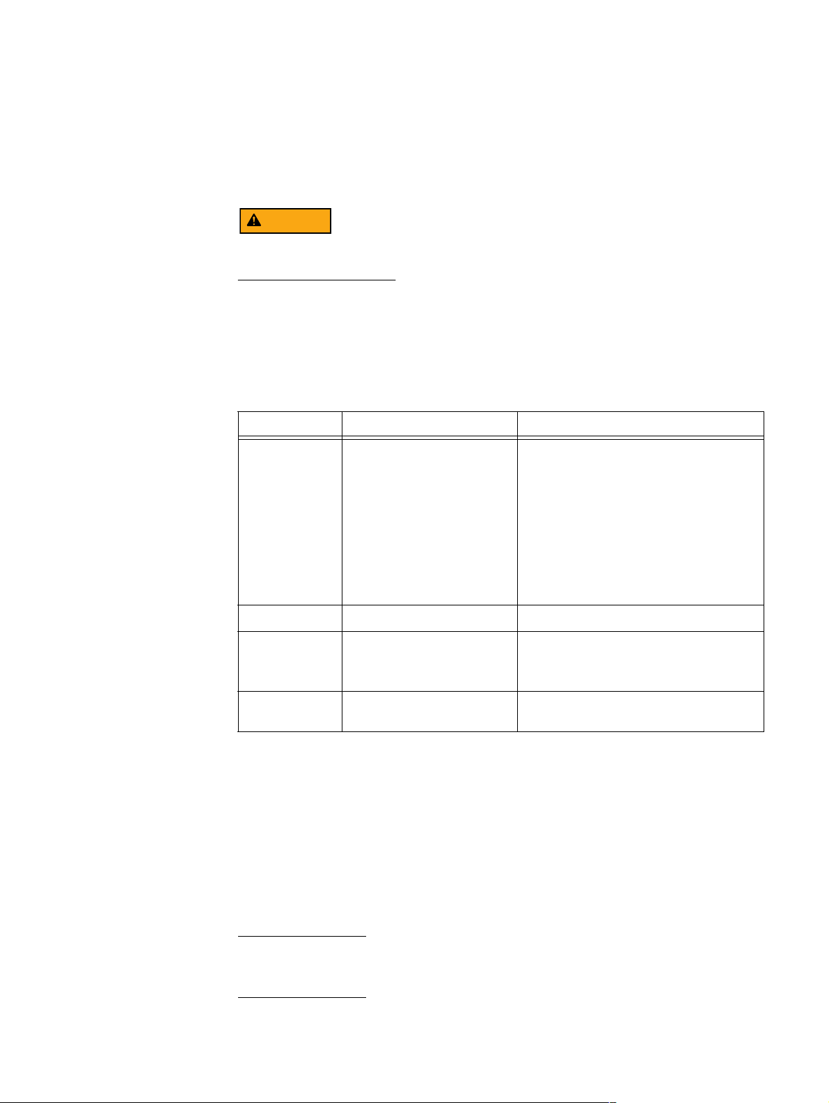
The following table presents the revision history of this document:
Revision Date Description
04 February 25, 2015 The following sections were updated:
• SP Power supply (page 33)
• Four-port 16 Gb/s optical FC I/O module
(page 51)
• 3U, 120 (2.5-inch) DAE “3U, 120
(2.5-inch) DAE (DAE8S)” on page 94
• Appendix B, Alum-A-Lift “Appendix B:
Field lift tool and accessory kit” on
page 168
•
Miscellaneous edits
03 January 27, 2014 Miscellaneous edits
02 October 30, 2013 The following sections were updated:
• Table 5 on page 22
• “VNX8000 DAE cabling” on page 130
01 July 23, 2013 First release of the
Information Guide
Product software and hardware release revisions
As part of an effort to improve its product lines, EMC periodically releases revisions of its
software and hardware. Therefore, some functions described in this document might not
be supported by all versions of the software or hardware currently in use. The product
release notes provide the most up-to-date information on product features.
Contact your EMC representative if a product does not function properly or does not
function as described in this document.
Note: This document was accurate at publication time. New versions of this document
might be released on the EMC online support website. Check the EMC online support
website to ensure that you are using the latest version of this document.
VNX8000 Hardware
2 EMC VNX8000 Hardware Information Guide
Page 3
Where to get help
EMC support, product, and licensing information can be obtained as follows:
Product information — For documentation, release notes, software updates, or
information about EMC products, licensing, and service, go to the EMC Online Support
website (registration required) at:
https://Support.EMC.com
Technical support — For technical support, go to EMC online support website (registration
required) and select Support. On the Support page, you will see several options, including
one to create a service request. Note that to open a service request, you must have a valid
support agreement. Contact your EMC sales representative for details about obtaining a
valid support agreement or with questions about your account.
How this document is organized
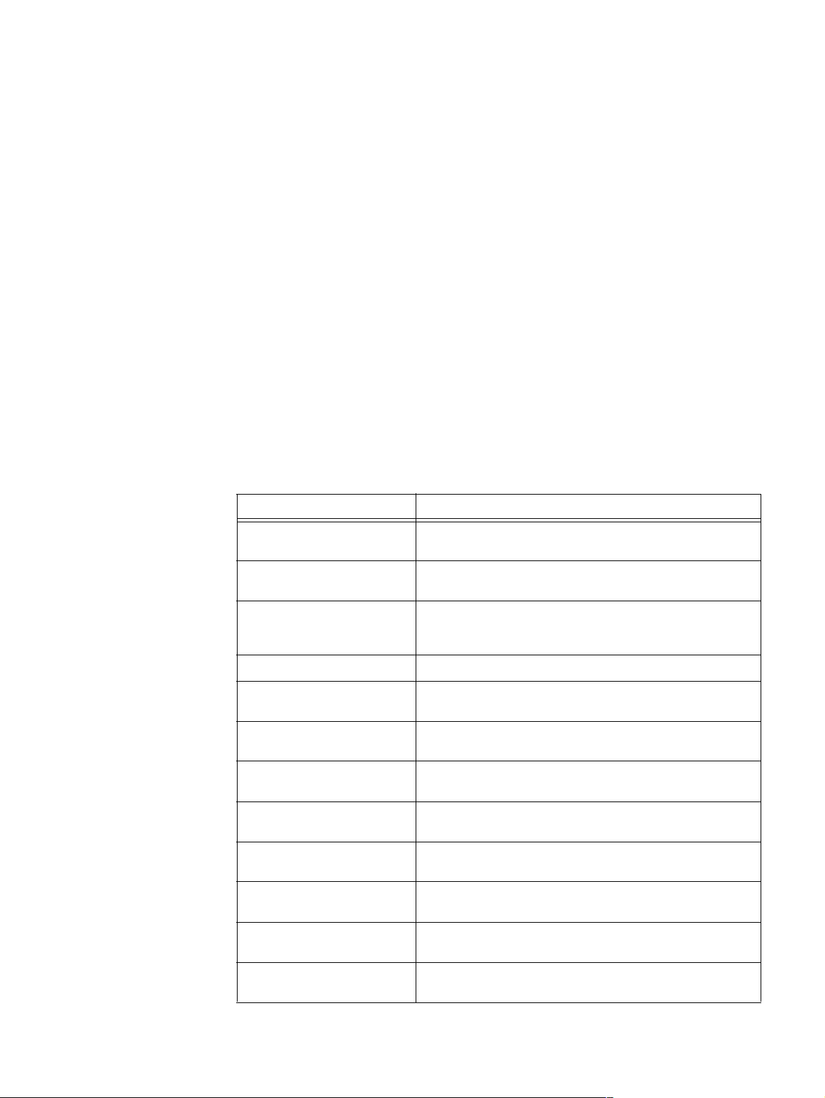
The major sections of this guide are listed in Table 1.
.
Where to get help
Table 1 Organization
Title Description
“Overview” on page 5 Describes the software and hardware features of a typical
VNX8000 along with a front view example of the VNX8000.
“VNX8000 product description”
on page 6
“System component
description” on page 13
“SPS front view” on page 14 Describes and illustrates the 2U SPS used in the VNX8000.
“SPE front view” on page 17 Describes and illustrates the front view of the SPE used in the
“Data Mover enclosure front
view” on page 24
“Control Station front view” on
page 21
“SPS rear view” on page 26 Describes and illustrates the rear view of the SPS used in the
“SPE rear view” on page 32 Describes and illustrates the rear of an SPE and the
Describes and shows the front and rear views of a typical File
and Unified VNX8000.
Provides a description of the components that comprise a File
and Unified VNX8000. Along with a description, illustrations of
each component are also shown.
VNX8000.
Describes and illustrates the front view of a DME and the
components that comprise it.
Describes and illustrates the front view of the Control Station
used in the VNX8000.
VNX8000.
components that comprise the rear of the SPE.
“Control Station rear view” on
page 37
“Data Mover enclosure rear
view” on page 42
“I/O modules” on page 45 Describes and illustrates the types of I/O modules supported in
Describes and illustrates the rear view of the Control Station
used in the VNX8000.
Describes and illustrates the rear of a DME and the components
that comprise it.
the File and Unified VNX8000.
EMC VNX8000 Hardware Information Guide 3
Page 4
Related documentation
IMPORTANT
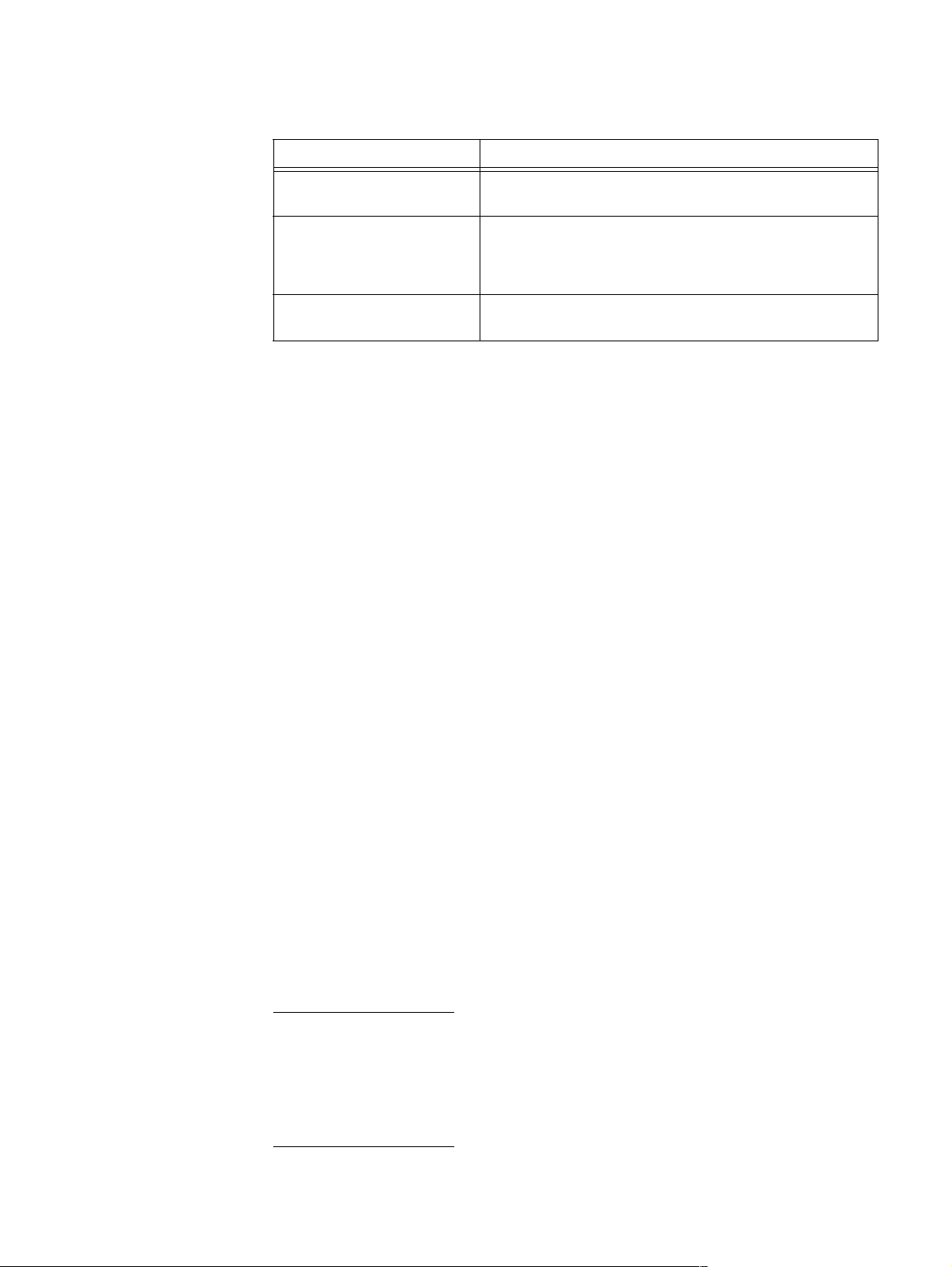
Table 1 Organization (continued)
Title Description
“Disk-array enclosures” on
page 73
“VNX8000 DAE cabling” on
page 130
“Appendix B: Field lift tool and
accessory kit” on page 168
Related documentation
EMC provides the ability to create step-by-step planning, installation, and maintenance
instructions tailored to your environment. To create VNX customized documentation, go
to: https://mydocs.emc.com/VNX/.
To download a PDF copy of the desired publication, go to the following sections:
◆ For hardware-related guides, go to About VNX, then select Learn about VNX hardware.
Next, follow the steps in the wizard.
◆ For technical specifications, go to About VNX section, then select View technical
specifications. Next, follow the steps in the wizard.
◆ For installation, adding, or replacing tasks, go to the VNX tasks section, then select the
appropriate heading. For example, to download a PDF copy of the
Installation Guide
Describes and illustrates the three types of DAEs available for
the File and Unified VNX8000.
Describes the types of DAE cabling available for the Block and
File/Unified VNX8000 platform. The cabling can be either
stacked or interleaved depending on your specific
requirements.
Describes the type of portable (mechanical) lift and accessory
kit used for lifting hardware components into a rack.
VNX8000 Block
, go to Install VNX, and follow the steps in the wizard.
Safety warnings
◆ For server-related tasks, go to the VNX Server tasks section, then select the
appropriate heading. For example, to download a PDF copy of Adding or replacing
server hardware, go to VNX Server tasks, and select Add or replace server hardware.
Next, follow the steps in the wizard.
Safety warnings appear throughout this publication in procedures that, if performed
incorrectly, might harm you or damage the equipment. A caution or warning symbol
precedes each safety statement. The safety warnings provide safety guidelines that you
should follow when working with any equipment that connects to electrical power or
telephone wiring.
The portable (mechanical) lift tool described in “Appendix B: Field lift tool and accessory
kit” on page 168 is recommended as a safety precaution when lifting EMC components
into an EMC or customer-provided rack. As described in the appendix, many of the EMC
components are too heavy to be lifted by one person or in some cases by two persons. As
a result, this portable (mechanical) lift tool is a necessary safety requirement, especially
when lifting EMC components like the 3U, 120 and the 4U, 60 DAEs.
4 EMC VNX8000 Hardware Information Guide
Page 5

Overview
Safety warnings
The EMC VNX series implements a modular architecture that integrates hardware
components for Block, File, and Object with concurrent support for native NAS, iSCSI,
Fiber Channel, and Fibre Channel over Ethernet (FCoE) protocols. The VNX series is based
on Intel Xeon-based PCI Express 3.0 processors and delivers File (NAS) functionality via
two to eight Data Movers and Block (iSCSI, FCoE, and FC) storage via dual storage
processors using a full 6-Gb/s SAS disk drive topology. The VNX Series is targeted at the
entry-level to high-end/large-capacity storage environments that require advanced
features, flexibility and configurability. The VNX Series provides significant advancements
in efficiency, simplicity, and performance.
Benefits include:
◆ Support for File (CIFS and NFS), Block (FC, iSCSI & FCoE) and Object
◆ Simple conversions when starting with a VNX Series Block only platform by simply
adding File services or starting with File only and adding Block services
◆ Support for both block and file auto-tiering with Fully Automated Storage Tiering
(FAST) for Virtual Pools (VP - FAST VP)
◆ Unified replication with RecoverPoint support for both file and block data
◆ Updated unified management with Unisphere now delivering a more cohesive unified
user experience
Offering Block and File services, Block services only, or File services only, the VNX8000
platform is positioned as a high-end storage platform. For a quick look at the VNX8000
platform hardware features, see Table 2, “Block and File VNX8000 platform hardware
feature quick reference,” on page 9.
In a Block services configuration, the VNX8000 platform supports a 4U SPE (SPE9), two 2U
dual SPSs, and four types of DAEs. The DAEs supported are a 25 drive 2.5-inch disk 2U
enclosure (or DAE5S), a 15 drive 2.5- or 3.5-inch disk 3U enclosure (or DAE6S), a 120
drive 2.5-inch disk 3U enclosure (or DAE8S), and a 60 drive 2.5- or 3.5-inch disk 4U
enclosure (or DAE7S). Expansion up to sixty 2U, 25 DAEs (a maximum of 1,500 2.5-inch
disk drives), of up to one-hundred 3U, 15 DAEs (a maximum of 1,500 2.5- or 3.5-inch disk
drives), up to twelve 3U, 120 DAE (a maximum of 1,440, 2.5-inch disk drives), or up to
twenty-five 4U, 60 DAEs (a maximum of 1,500 2.5- or 3.5-inch disk drives) is supported.
Note: When the 3U, 120 and 4U, 60 DAEs are implemented in the VNX8000 platform, the
40U Dense rack is required because of the depth of the 3U, 120 and the 4U, 60 DAEs.
In a File services or a Block and File services configuration, the VNX8000 platform
supports a 4U SPE, from one to two 1U Control Stations (CS0 and CS1), two to four 2U
Data Mover enclosures having two to eight Data Movers
1
, two 2U dual SPSs, and four
types of DAEs. The DAEs supported are a 25 drive 2.5-inch disk 2U enclosure (or DAE5S),
a 15 drive 2.5- or 3.5-inch disk 3U enclosure (or DAE6S), a 120 drive 2.5-inch disk 3U
enclosure (or DAE8S), and a 60 drive 2.5- or 3.5-inch disk 4U enclosure (or DAE7S).
1. The term Data Mover is used throughout this guide. The term Data Mover is also referred to as a
blade. These terms are interchangeable and mean the same.
EMC VNX8000 Hardware Information Guide 5
Page 6

VNX8000 product description
Expansion up to sixty 2U, 25 DAEs (a maximum of 1,500 2.5-inch disk drives), of up to
one-hundred 3U, 15 DAEs (a maximum of 1,500 2.5- or 3.5-inch disk drives), up to twelve
3U, 120 DAE (a maximum of 1,440, 2.5-inch disk drives), or up to twenty-five 4U, 60 DAEs
(a maximum of 1,500 2.5- or 3.5-inch disk drives) is supported.
Note: The Block or the File and Unified services configuration of the VNX8000 platform can
have a mix of DAE types to conform to your specific requirements. In other words, you can
have a mix of 2U DAEs, 3U DAEs, and 4U DAEs in the same environment so as long as the
VNX8000 platform does not have no more than the supported amount of 1,500 disk
drives.
VNX8000 product description
This section shows examples of the front and rear views of a File/Unified VNX8000
platform. These are only examples with two DMEs and a Vault DAE. A typical File/Unified
VNX8000 could be comprised of up to four DMEs and up to several DAEs.
Note: The File/Unified VNX8000 platform described in this guide includes information
about the 2U and 3U DAEs in a typical rack/cabinet environment. A File/Unified VNX8000
platform having all 4U DAEs or a mix of 2U, 3U, or 4U DAEs is typically built by
manufacturing in a Dense rack environment.
6 EMC VNX8000 Hardware Information Guide
Page 7
Front view
14
0
VNX8000 product description
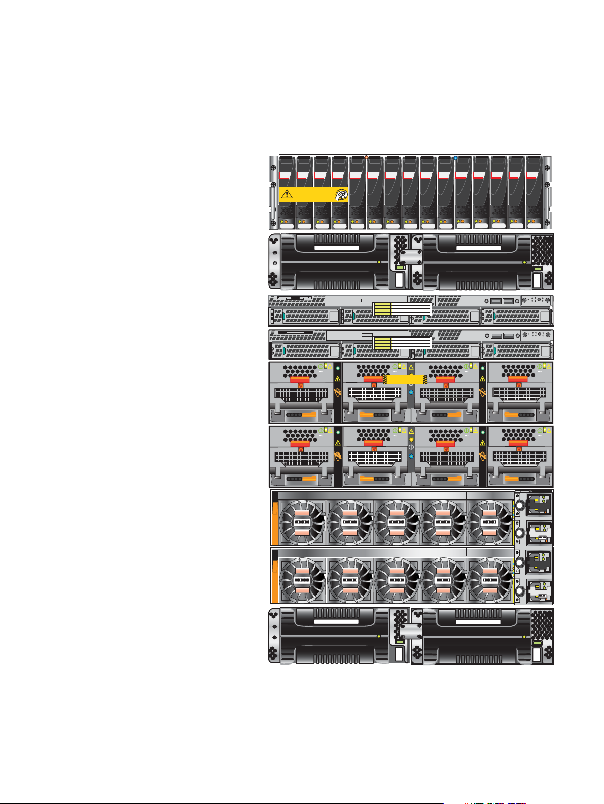
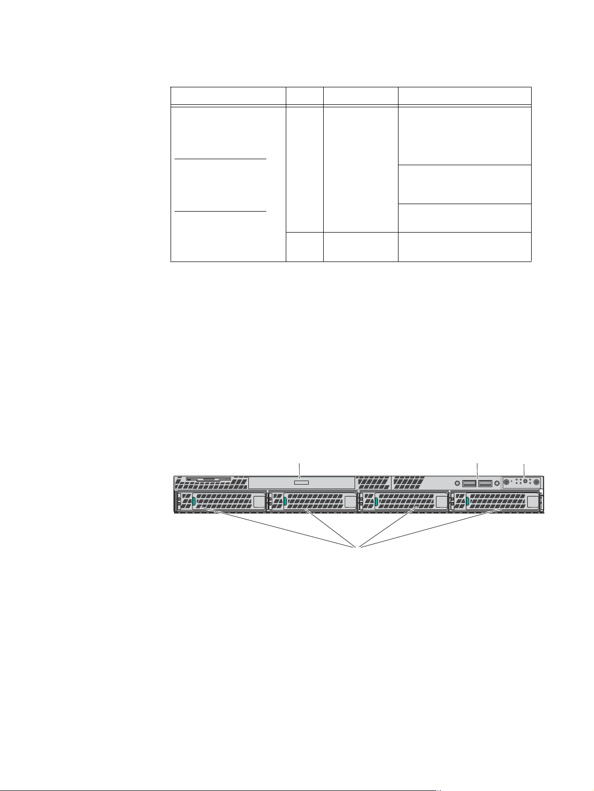
Figure 1 shows an example of the front view of a File/Unified VNX8000 platform having a
4U SPE, two 1U Control Stations (one optional), two dual SPSs (one for the SPE and one
for the Vault DAE), two 2U Data Mover enclosures with four Data Movers, and a Vault DAE.
SAS SAS SASSASSAS
Disk-array
SAS SASSASSASSAS
Caution: Array Software on drives 0-3. Removing or relocating them
Will Make the Array Unusable
SAS SASSASSASSAS
enclosure 0
DAE standby
power supply
Control Station 1
(optional)
Control Station 0
Data Mover
AC
AC
Blade Enclosure 1
Remove Prior to powering up equipment
046-003-752_A01
AC
AC
enclosure 1
Data Mover
AC
AC
AC
AC
enclosure 0
Storage
processor
enclosure
SPE standby
power supply
Figure 1 Example of a File/Unified VNX8000 platform (front view)
EMC VNX8000 Hardware Information Guide 7
VNX-000559
AC
DC
AC
!
DC
!
AC
!
AC
DC
!
AC
DC
AC
!
!
AC
DC
AC
!
DC
!
AC
!
AC
DC
!
AC
DC
AC
!
!
Page 8

VNX8000 product description
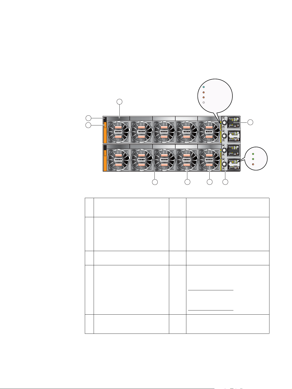
Rear view
Figure 2 on page 8 shows an example of the rear view of a File/Unified VNX8000 platform
having a 4U SPE showing the two storage processors (SP A and B), two 1U Control
Stations (one optional), two dual 2U SPSs (one for the SPE and one for the Vault DAE), two
2U Data Mover enclosures with four Data Movers, and one 2U DAE (the Vault DAE).
#
X4
X4
6 Gb
SAS
B
Disk-array
enclosure 0
DAE standby
power supply
Control Station 1
(optional)
Control Station 0
X4
#
MGMT
1
IOIO
MGMT
IOIO
CS
1
CS
A
6 Gb
SAS
X4
2
2
B MGMT
A
B MGMT
A
MGMT
B
MGMT
B
Data Mover
enclosure 1
Data Mover
enclosure 0
Storage
processor
enclosure
SPE standby
power supply
123
0
0
123
0
Data Mover 5
123
0
123
0
Data Mover 4
0
Data Mover 2Data Mover 3
0123
0123
123
0
123
0
0123
0123
VNX-000560
Figure 2 Example of a File/Unified VNX8000 platform (rear view)
8 EMC VNX8000 Hardware Information Guide
Page 9
Hardware features
VNX8000 product description
Contained in a 14U architecture, the File/Unified VNX8000 platform weighs approximately
284.2 lb (626.5 kg) fully loaded without I/O modules and DAEs. With the 4U SPE having
the deepest dimension within the cabinet, the File/Unified VNX8000 without DAEs
measures (14U) 27 inches high x 17.6 inches wide x 31 inches deep (68.58 cm x 44.7 cm
x 78.74 cm). Between the front and rear of the enclosure, a midplane distributes power
and signals to all the enclosure components. On the front of the VNX8000 SPE, the power
supplies, cooling fan modules, and disk drives plug directly into the midplane
connections. On the rear of the VNX8000 SPE, power supply connector modules,
management modules, and I/O modules plug directly into the midplane connections.
Note: The previously mentioned dimensions are approximate and do not include any I/O
modules, DAEs, or the cabinet enclosure.
For more information about the weight and dimensions of a VNX8000 platform, go to
https://mydocs.emc.com/VNX/ and go to the About VNX section, and then select View
technical specifications. Next, follow the steps in the wizard.
Table 2 Block and File VNX8000 platform hardware feature quick reference
Block File
Config.
Minimum
form
factor
4U w/out
optional
CS, DME,
SPSs,
and DAEs
1. For the type and number of Ultraflex I/O modules supported in the SP, refer to the I/O module section on page 47.
2. For the type and number of Ultraflex I/O modules supported in the DM, refer to the I/O module section on page 63.
3. pNFS = parallel-NFS
Maximum
# of
drives
1,500 6-Gb/s
Drive
types
2.5 or
3.5 in.
SAS
and
2.5 or
3.5 in.
Flash
I/O
slots
per SP
1
11
Built-in
I/O ports
per SP SPs
None 2 128 GB FC, iSCSI,
System
memory
per SP Protocols
and FCoE
Config.
I/O slots
per DM DMs
5 2 to 8
Configured for AC-input power, the Block VNX8000 includes the following hardware
features:
◆ Two 2U dual SPSs (one for the SPE and one for the Vault DAE):
• On the front, the 2U dual SPS has two SPSs (SPS A on the left and SPS B on the
right).
System
memory
per DM Protocols
2
24 GB NFS,
CIFS,
and
pNFS
3
Each SPS consists of:
– A removable battery installed in an SPS tray within the 2U dual SPS enclosure;
each battery has one power on LED (green)
EMC VNX8000 Hardware Information Guide 9
Page 10

VNX8000 product description
• On the rear, each SPS consists of:
– One power on/off rocker switch
– One AC power in connector (recessed plug)
– Four DC power out connectors (sockets)
– Four status LEDs (on-line power, on-battery, no battery, and internal fault)
– One RJ-12 management connector
◆ One 4U SPE:
• On the front, each 4U SPE (Figure 2 on page 8) has two SPs (SP A on the bottom
half and B on the top half).
Each SP consists of:
– Five cooling fans; each fan has one LED; this LED is lit below each fan when
powering up and goes out when each fan is at the proper operating speed
Note: Each cooling fan is secured with push-tabs on the top and bottom of the
fan.
– Two CPU modules with an Intel Xeon 8-core 2.7-GHz processor facilitating
Simultaneous Multi-Threading (SMT).
– Sixteen Double Data Rate Three (DDR3) synchronous dynamic RAM (SDRAM)
slots supporting up to 128 GB of SDRAM per CPU module or SP using 8 GB
DIMMs
– Four internal 2.5-inch SAS/SATA hard drive slots (not used at this time)
– Four LEDs; SP power (blue), SP chassis fault (amber), SP fault (blue/amber),
and SP unsafe-to-remove (white)
Note: The SP is viewed as an enclosure within an enclosure (or SPE). Thus, an
SP chassis or enclosure fault LED (amber) is provided.
– Two power supplies with three LEDs [AC, DC, and DC fault (labeled with an !)];
each power supply has a built-in power cord within the power supply assembly
that runs along the power supply up the front where it is connected to two
recessed plugs (one gray, one black); see the rear of the SP power supply for
information about PDU power and SPS power connections (“Rear view” on
page 8)
• On the rear of the VNX8000, the 4U SPE (Figure 2 on page 8) has two SPs (SP A on
the bottom half and SP B on the top half).
Each SP consists of:
– One management module (see “Storage processor management module” on
page page 34 for more information) featuring:
a.) One RS-232/EIA 232 serial (up to 115 K baud) service laptop (micro DB-9)
port
b.) One RS-232/EIA 232 serial SPS management (micro DB-9) port
10 EMC VNX8000 Hardware Information Guide
Page 11

VNX8000 product description
c.) One 10/100/1000 LAN network management (RJ-45) port
d.) One 10/100/1000 LAN service (RJ-45) port
Note: The management module is secured with a latch handle (labeled MGMT).
– One power supply module (see “Storage processor (SP) AC power supply
module” on page 18 for more information) has:
a.) Two recessed power plugs (one gray and one black)
Note: The cables connected to the power supplies on PDU A/Zone A (right side,
facing rear) are colored gray and the cables on PDU B/Zone B (left side, facing
rear) are colored black.
b.) Two retaining bale clips; one per power connector or plug
– Ten PCI Gen 3, 8x lane I/O module slots (A0 – A9 and B0 – B9) and one PCI Gen
3, 16x lane I/O module slot (A10 and B10) are available for use, supporting:
Note: The maximum number of I/O modules for the VNX8000 is 11 per SP. Any
combination of the following I/O modules up to nine per Block SP and eight for
File/Unified SP. For more information about slot limitations, see “I/O module
slots” on page 47.
a.) Four-port 8-Gb/s FC optical (running at 2, 4, or 8 Gb/s); labeled 8 GbE Fibre
on the latch handle
Four-port 16-Gb/s FC optical (running at 4, 8, or 16 Gb/s); labeled
16 GbE Fibre v1 on the latch handle
b.) Four-port 1-Gb/s Base-T iSCSI I/O module; labeled 1 GbE iSCSI/TOE on the
latch handle
c.) Two-port 10-Gb/s optical or active Twinax5; labeled 10 GbE v3 on the latch
handle
d.) Two-port 10-Gb/s RJ45 Base-T iSCSI/IP; labeled 10 GbE Base-T on the latch
handle
e.) Two-port 10-Gb/s Fibre Channel over Ethernet (FCoE); labeled 10 GbE/FCoE
on the latch handle
f.) Four-port 6-Gb/s SAS; labeled 6 Gb SAS v3 with an e inside a lock symbol on
the latch handle (in slots A5, B5, and A10, B10)
Note: The e inside the lock symbol indicates that the I/O module supports
encryption.
◆ One to four 2U DMEs:
• On the front, the VNX8000 has from one to four DMEs having two to eight Data
Movers (DMs). Each DM consists of:
–One CPU module
– Two power supply/cooling modules
EMC VNX8000 Hardware Information Guide 11
Page 12

VNX8000 product description
• On the rear, the VNX8000 has from one to four DMEs having two to eight Data
Movers (DMs). Each DM consists of:
– One management module (see “Data Mover management module” on page 42
for more information) featuring:
a.) One RS-232/EIA 232 serial (up to 115 K baud) service laptop (micro DB-9)
port
b.) Three 10/100/1000 LAN network management (RJ-45) ports
Note: The management module is secured with a latch handle (labeled MGMT).
– One CPU module consisting of one Intel Xeon 6-core 2.8-GHz processor. The
CPU modules in the DME contain the power, fault, and unsafe-to-remove LEDs
(see “CPU” on page 25 for more information).
– Six DDR3 synchronous dynamic RAM (SDRAM) slots supporting up to 24 GB per
CPU module using 2 or 4 GB DIMMs
– Five PCI Gen 2, 8x lane I/O module slots (0 – 4) available for use, supporting:
Note: The maximum number of I/O modules for the VNX8000 is five per DM. One
FC I/O module and up to three other I/O modules. Any combination of these I/O
modules must be the same for both Data Movers.
a.) One Fibre Channel (FC) I/O module with a:
– Four-port 8-Gb/s optical (running at 2, 4, or 8 Gb/s); in slots A0 and B0
only; labeled 8 GbE Fibre on the latch handle
b.) One or two of the following network I/O modules in any combination:
– Two-port 10-Gb/s optical or active Twinax; labeled 10 GbE v3 on the
latch handle
– Four-port 1-Gb/s copper; labeled 1 GbE on the latch handle
– Two-port 10-Gb/s RJ45 Base-T iSCSI/IP; labeled 10 GbE Base-T on the
latch handle
◆ One to two 1U Control Stations
◆ Expansion of up to sixty 2U, 25 DAEs (a maximum of 1,500 2.5-inch disk drives), of up
to on-hundred 3U, 15 DAEs (a maximum of 1,500 2.5- or 3.5-inch disk drives), up
twelve 3U, 120 DAEs (a maximum of 1,440 2.5-inch disk drives), or up to twenty-five
4U, 60 DAEs (a maximum of 1,500 2.5- or 3.5-inch disk drives) is supported.
◆ Any required cables including LAN cables, modem cables, and serial DB-9 cable.
◆ Mounting rails with hardware
◆ Front bezel with VNX8000 badge
12 EMC VNX8000 Hardware Information Guide
Page 13

System component description
IMPORTANT
This section describes the VNX8000 platform components. Included in this section are
illustrations and descriptions of the front and rear connectors as well as the LED
indicators.
Note: In the following sections, the illustrations and corresponding tables describe these
individual components. These descriptions are for illustrative purposes only.
Installing, replacing, and removing faulted hardware components
Separate documents provide instructions for installing, replacing, and removing hardware
components in the VNX8000 platform. For more information, refer to the respective
document for the correct procedure. These documents are available online at
https://mydocs.emc.com/VNX/ and go to VNX tasks, then select Add VNX hardware. Next,
follow the steps in the wizard.
System component description
Example:
VNX8000 front view
To replace a power supply/cooling module in the SPE9 of a VNX8000, go to the
a storage processor power supply/cooling module or fan module
procedures to replace a power supply/cooling module in a SPE9 storage processor
enclosure. This procedure is available online at https://mydocs.emc.com/VNX/ and go to
VNX tasks, then select Add VNX hardware. Next, follow the steps in the wizard.
As previously described, the File/Unified VNX8000 platform is made up of a 4U SPE, one
to two 1U Control Stations (one optional), two SPSs (one for the SPE and the other for the
Vault DAE), and one to four 2U DMEs with two to eight DMs. The following sections
describe the front view (Figure 1 on page 7) of the VNX8000 platform components.
The VNX8000 platform requires two dual 2U SPSs. One for the 4U SPE and one for the
Vault DAE. The 2U SPS contains two 2U 2.2-kilowatt Lithium-ion batteries housed in a
separate 2U tray. One set of 2U SPS batteries provides backup power to the storage
processors in the 4U storage processor enclosure (SPE). This set of SPS batteries is
referred to as either the SPE SPS or SPS 0. The other set of 2U SPS batteries provides
backup power to the Bus 0 Enclosure 0 DAE. This set of SPS batteries is referred to as
either the Bus 0 Enclosure 0 SPS or SPS 1.
document for the correct
Replacing
EMC VNX8000 Hardware Information Guide 13
Page 14
System component description
SPS front view
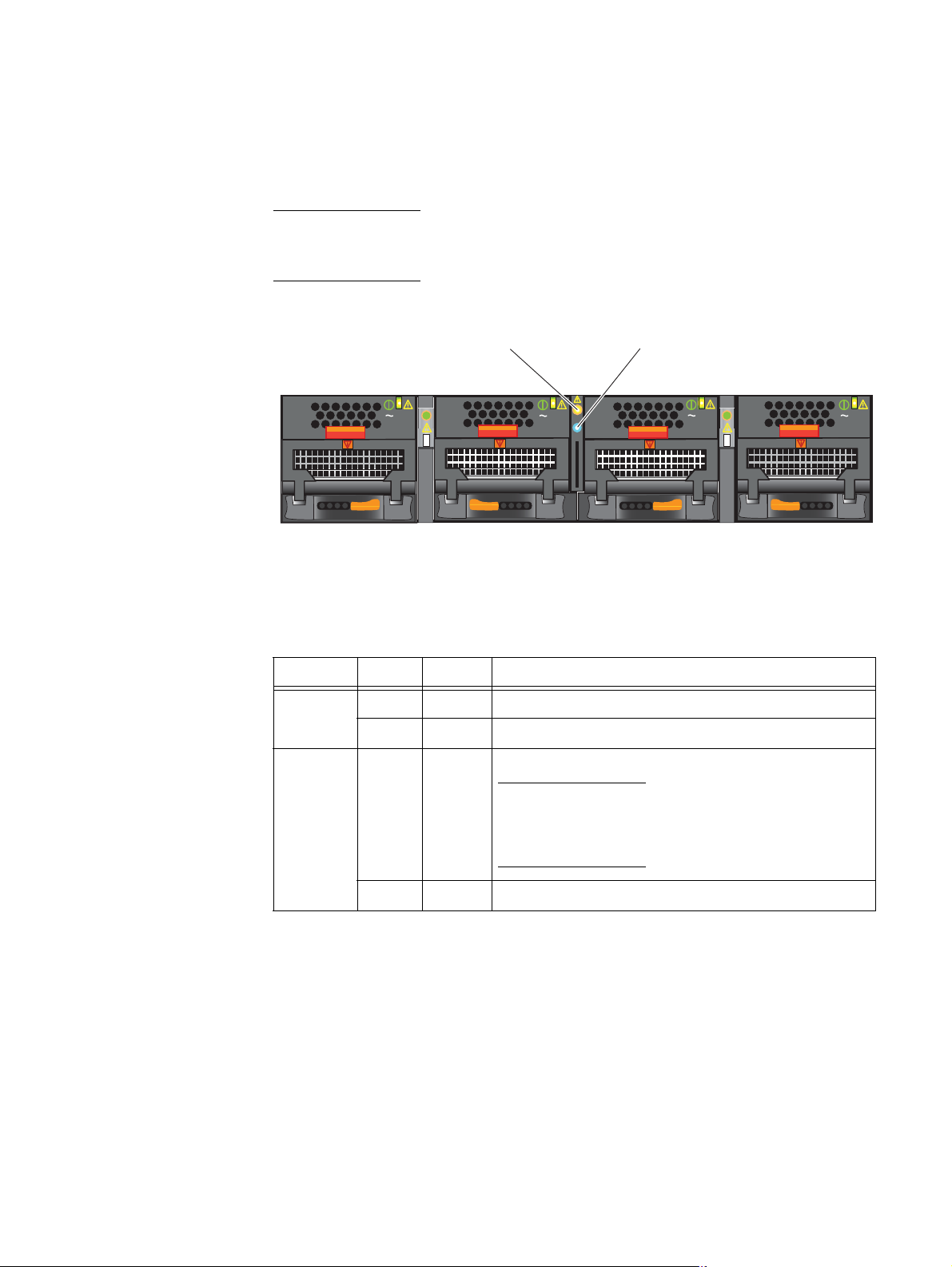
The front of the VNX8000 platform 2U dual SPS (Figure 3) shows two SPSs with one LED
per SPS (power), SPS battery tray, SPS battery color wheel latch indicator.
1
2
3
6
VNX-000561
1 SPS A battery 4 SPS B tray
2 SPS A tray 5 SPS B battery color wheel latch indicator
• Green = engaged
• Yellow = parked
• Red = not engaged
3 SPS B Lithium ion (Li-ion) battery 6 SPS A power on LED (green)
Figure 3 Example of 2U dual SPS (front view)
4
5
SPS battery
The SPS battery is a Lithium-ion (Li-ion) battery. The SPS battery has a handle on the front
allowing for ease of insertion and removal (Figure 4 on page 15). When installing the
Li-ion battery, you must engage it before you power on the system. Depending on how
your storage system was shipped to your site, the installation requirements for the SPS
battery will be different.
Note: The SPS battery weighs approximately 28 lb (12.07 kg).
◆ If your storage system is shipped in an EMC rack by truck, the factory inserts the
battery into the SPS enclosure in the SPS tray, but does not engage it. The SPS battery
is in the parked position (wheel latch indicator yellow) inside the SPS enclosure. You
must lift the wheel latch up and push the SPS battery further into the slot of the SPS
enclosure to ensure that it is in the engaged position (wheel latch indicator green).
◆ If your storage system is shipped in an EMC rack by air, the factory ships the SPS
battery separately. The battery is not installed in the cabinet or rack, and the wheel
latch indicator on the SPS enclosure is red. You must unpack the SPS battery from the
separate shipping container, install it in the SPS enclosure, and then ensure that the
SPS enclosure is engaged (wheel latch indicator green).
14 EMC VNX8000 Hardware Information Guide
Page 15

System component description
IMPORTANT
◆ If your storage system is shipped in a shipping rack (the storage system components
will be removed and put into a customer rack), the factory inserts the battery into the
SPS enclosure in the SPS tray, but does not engage it. The SPS battery is in the parked
position (wheel latch indicator yellow). You must lift the wheel latch up and push the
SPS battery further into the slot of the SPS enclosure to ensure that it is in the
engaged position (wheel latch indicator green).
Label
Air vents
Pull handle
Latching features
LED indicator
Figure 4 Example of SPS LI-ion battery
SYM-002673
Unpacking or removing the SPS battery
To unpack or remove the SPS battery:
Attach an antistatic wrist strap to your wrist and connect its cord to a known ground.
1. If shipped separately, unpack the SPS batteries from the shipping containers.
2. Place the batteries separately on an antistatic floor, mat, or workbench pads.
3. If shipped in a shipping rack, remove the SPS batteries from the shipping rack.
4. Place the batteries separately on an antistatic floor, mat, or workbench pads.
EMC VNX8000 Hardware Information Guide 15
Page 16
System component description
IMPORTANT
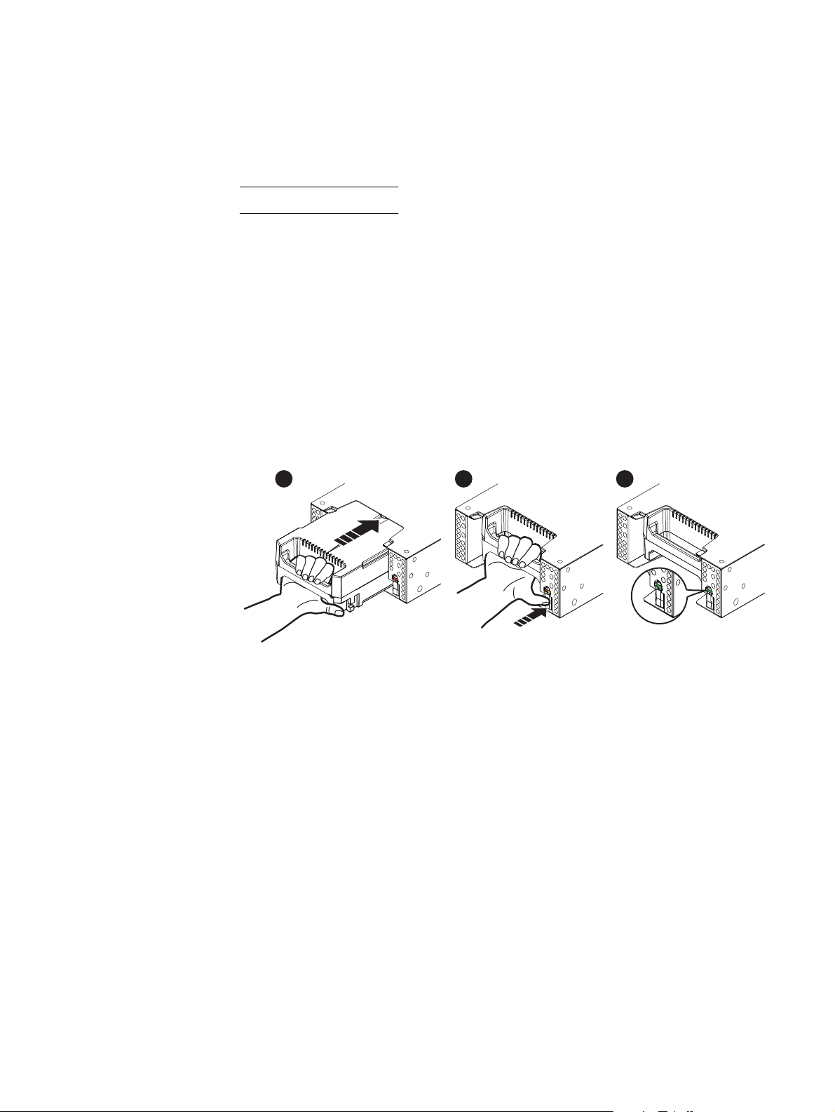
Installing the SPS battery
To install the Li-ion SPS battery:
Attach an antistatic wrist strap to your wrist and connect its cord to a known ground.
1. If the SPS battery shipped separately (SPS enclosure wheel latch indicator red),
position the battery with the LED indicator on the right and slide it into the SPS
enclosure (see location 1 in Figure 5).
2. “Park” the battery by lifting the wheel latch up on the SPS enclosure and pushing the
battery completely into the SPS enclosure slot (see location 2 in Figure 5).
The SPS battery will click into place and the wheel latch indicator will be yellow.
3. “Engage” the SPS battery by pressing the wheel latch while pushing the SPS battery
further into the SPS enclosure slot (see location 2 in Figure 5)
The SPS battery will click into the final position and the wheel latch indicator will be
green (see location 3 in Figure 5).
Figure 5 Example of installing the SPS Li-ion battery
321
SYM-002699
16 EMC VNX8000 Hardware Information Guide
Page 17
SPE front view
System component description
The front of the VNX8000 platform 4U SPE shows four hard drives with two LEDs per drive
(power and fault), five fan modules with one LED per module (fault), four power supplies
with three LEDs per power supply (AC, DC and DC fault). Four status LEDs per SP: one SP
power on, one SP chassis (enclosure) fault, one SP fault, and one SP unsafe to remove.
SP power on
SP chassis fault
3
SP fault
SP unsafe to remove
Detail 1
2
1
8
1 Latch (orange) for SP B (one per SP);
push down to unlock SP from SPE
chassis
2 Lock latch handle (black) for SP B (one
per SP); after unlocking with the
orange latch (see location 1), pull the
black latch handle horizontally across
the top to release the SP from the SPE
chassis
3 SP B hard drive slot (not used at this
time)
AC
DC
!
4
AC
DC
!
AC
DC
!
AC
DC
!
AC
DC
!
Detail 2
567
VNX-000566
6 SP A fan module push tabs (push together
to unlock fan), then pull out to release
7 SP A fan module
8 SP A fan fault icon for fault LED (10 places)
4 SP A power supply Detail 1SP A status LEDs; SP power on (blue), SP
chassis (enclosure) fault (amber), SP fault
(blue/amber), and SP unsafe to remove
(white)
Note: On the inner right side (around the
corner) of the SP, LED labels for the SP and
the SP chassis (enclosure) are shown.
5 SP B power supply recessed
connectors (plugs); two per SP (one
Detail 2SP A power supply LEDs; AC, DC and fault
(labeled with !)
gray and one black)
Figure 6 Example of SP components (front view)
EMC VNX8000 Hardware Information Guide 17
Page 18
System component description
Storage processor (SP) AC power supply module
The storage processor enclosure (SPE) contains four power supply modules, two per
storage processor, which provide redundant power to each storage processor CPU
module, midplane, and other hardware components. A latch on the power supply locks it
into place to ensure proper connection. When viewed from the front, the SP power supply
module is located on the right side of each SP (see location 4 in Figure 6 on page 17).
Each power supply includes three status LEDs (see Detail 2 in Figure 6 on page 17).
Do not
remove the SP power supply module while the SP is plugged in. Power supply
module removal for more than a few minutes can cause the SP to shut down due to lack of
cooling.
Table 3 describes the VNX8000 platform fan fault and SP power supply status LEDs as
shown in Figure 6 on page 17.
Table 3 VNX8000 platform SP fan fault and SP power supply status LEDs
LED Color State Description
Fan fault (see location 10) Amber On Fan fault
— Off Fan operating normally
SP A power supply status
(see Detail 2)
Green On SP A AC power supply (input)
power on LED, labeled AC
— Off SP A AC power supply (input) off,
verify source power
Green On SP A DC power supply (output)
power on LED, labeled DC
— Off SP A DC power supply (output)
off, verify source power
Amber Fault SP A DC power supply (output)
fault LED, labeled with an
exclamation point (!)
Blinking BIOS, POST and OS booting up or
system overheating
SP and SP chassis (enclosure) LEDs
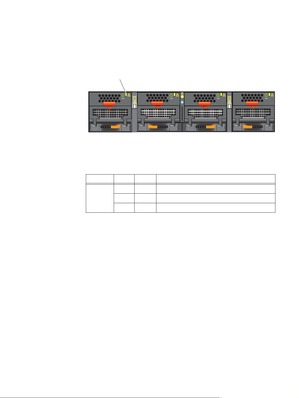
The SPs in the 4U storage processor enclosure contain the SP power on, SP chassis
(enclosure) fault, SP fault, and SP unsafe to remove LEDs (see Detail 1 in Figure 6 on
page 17). Reading from the top of the exploded view in Figure 7 on page 19, the LEDs are:
the SP power on, SP chassis (enclosure) fault, SP fault, and SP unsafe to remove,
respectively.
18 EMC VNX8000 Hardware Information Guide
Page 19
System component description
CL5214
Figure 7 Example of SP power on, SP chassis (enclosure) fault, SF fault, and SP unsafe to remove
LEDs
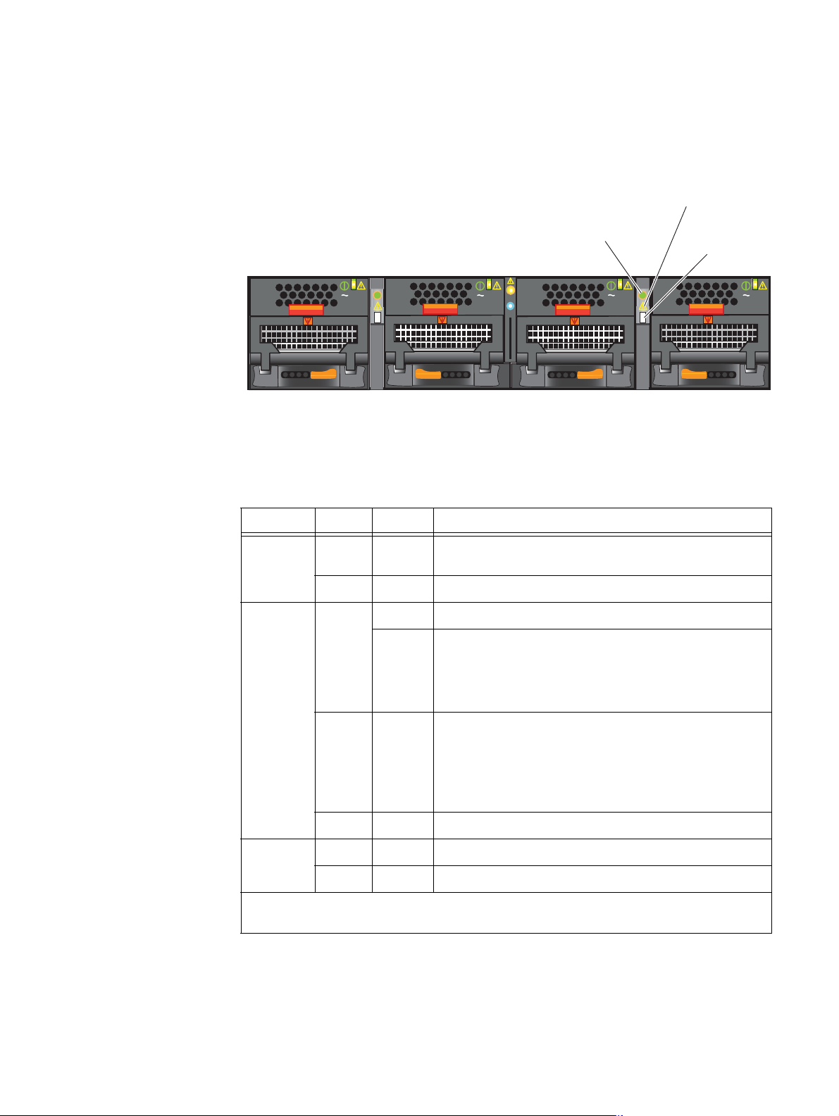
Table 4 describes the SP and SP chassis (enclosure) status LEDs as shown in Figure 6 on
page 17 and Figure 7 on page 19.
Table 4 VNX8000 platform SP and SP chassis (enclosure) status LEDs
LED Color State Description
SP power (see Detail 1 in
Figure 6 on page 17 and
exploded view in Figure 7 on
page 19)
SP chassis (enclosure) fault
(see Detail 1 in Figure 6 on
page 17 and exploded view
in Figure 7 on page 19)
Blue On Powered up
— Off Powered down
Amber On Fault
•Power (PSU or SPS)
• Environmental (fans)
•I/O modules or LCCs
•SP
• CMI, SFP, Resume PROM
— Off Operating normally
EMC VNX8000 Hardware Information Guide 19
Page 20
System component description
Table 4 VNX8000 platform SP and SP chassis (enclosure) status LEDs (continued)
LED Color State Description
SP fault LED, behavior
during normal boot
(see Detail 1 in Figure 6 on
page 17 and exploded view
in Figure 7 on page 19)
SP fault LED, during
degraded boot
(see Detail 1 in Figure 6 on
page 17 and exploded view
in Figure 7 on page 19)
Amber On (steady) SP fault
Blinks once every
Executing BIOS
4 seconds
Blinks once every
Executing Post
second
Blinks four times
Post starting operating system
a second
Blue Blinks once every
Operating system booted
4 seconds
Blinks once every
1
SEP
driver start in progress
second
Blinks four times
SEP driver start completed
a second
— Off Operating system ready for input
or not powered up
Amber Blinks once every
Executing BIOS
4 seconds
Blinks once every
Executing Post
second
Blinks four times
Post starting operating system
a second
SP fault LED, during faults
(see Detail 1 in Figure 6 on
page 17 and exploded view
in Figure 7 on page 19)
Blue Blinks once every
Operating system booted
4 seconds
On Degraded mode
— Off Powered down or no fault
Amber On Fault has occurred
Blinks once every
2 seconds
NMI reset button pushed;
blinking will continue until SP
reboots and enters power on
sequence.
Blinks at 1, 3, 3,
Memory problem
and 1 times a
second
Blue On Fault has occurred
20 EMC VNX8000 Hardware Information Guide
Page 21
System component description
Table 4 VNX8000 platform SP and SP chassis (enclosure) status LEDs (continued)
LED Color State Description
Control Station front view
SP unsafe to remove
(see Detail 1 in Figure 6 on
page 17 and exploded view
in Figure 7 on page 19)
Note: One SP will always
have the unsafe to remove
LED on after a successful
White On The SP peer has a panic or
rebooted with the cache
performance mode enabled. The
SP is holding valid cache in
memory.
The SP is currently flashing the
BIOS/Post firmware or updating
the resume PROMs.
shut down.
The SP is currently dumping the
cache data to the vault.
— Off The SP can be safely removed for
service.
1. SEP = security processor
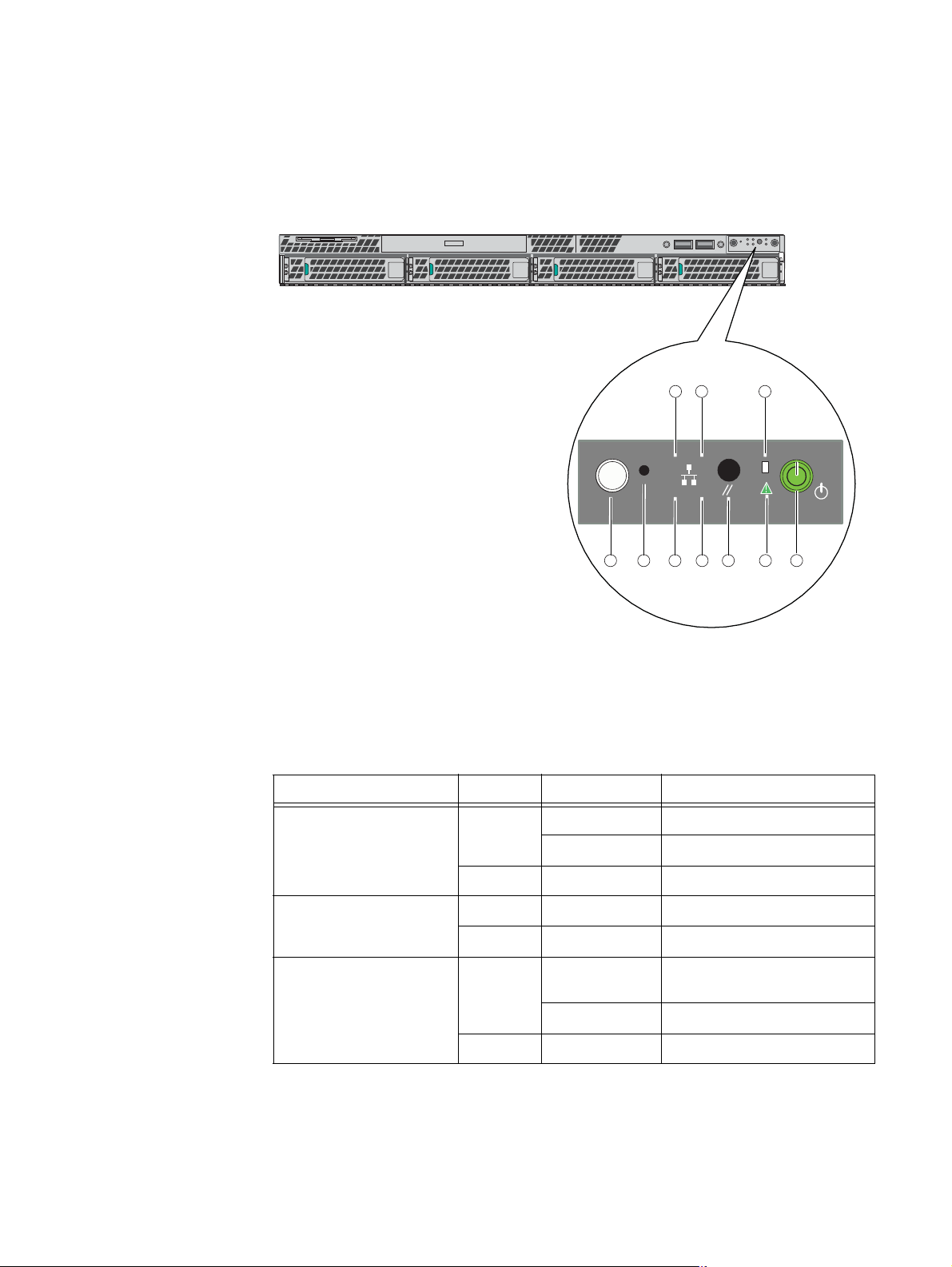
On the front, viewing from left to right, the File/Unified VNX8000 platform 1U Control
Station includes the following hardware components:
◆ One DVD-ROM drive
◆ Two USB 2.0 connectors (not used)
◆ Front control panel with various buttons and status LEDs
◆ Four hot-swappable SATA hard drive bays
Figure 8 shows the orientation of these components.
DVD-ROM drive USB 2.0 connectors Control panel
Hard drives
Figure 8 Example of a VNX8000 platform Control Station (front view)
VNX-000521
EMC VNX8000 Hardware Information Guide 21
Page 22
System component description
ID
123
4
Control Station front panel
Figure 9 shows the location of the File/Unified VNX8000 platform 1U Control Station front
panel.
Front
31 2
ID
678910
45
VNX-000549
Figure 9 VNX8000 platform Control Station front panel
Table 5 describes the Control Station front panel push buttons and LEDs.
Table 5 Control Station LEDs and push buttons
LED Color State Description
Onboard (integrated) LAN 2
and 4 (see locations 1 and
2, respectively)
Internal hard drive activity
(see location 3)
Power (see location 4) Green On Power on/system loaded and
Green On NIC link/no access
Blinking NIC link/LAN access
—Off Idle
Green Blinking Hard drive access
— Off No hard drive activity, no fault
ready
Blinking Sleep mode
22 EMC VNX8000 Hardware Information Guide
—Off Power off
Page 23
System component description
Table 5 Control Station LEDs and push buttons (continued)
LED Color State Description
Status/fault (see location 5) Green On Powered on; status ok
Blinking Powered on; degraded.
Redundancy lost, such as power
supply or fan failure, or
predictive power supply failure.
Amber On Critical fault: Voltage, thermal, or
power fault; CPU missing;
insufficient power unit
redundancy resource offset
asserted.
Blinking Non-critical failure: Critical
temperature/voltage
— Off Power off: System unplugged
Powered on: System powered off
and in standby, no prior
degradation/critical state.
Reset button
(see location 6)
— — Allows you to reset the CS. Same
as turning the power off and then
on again. Data loss will occur
unless you have saved the data.
The reset button would be used
when a program error occurs and
has caused the CS to freeze.
Pressing the reset button
performs a cold restart (reboot)
which goes through the initial
start-up stages including
memory check.
Onboard (integrated) LAN 1
Green On NIC link/no access
and 3 (see locations 7 and
8, respectively)
Blinking NIC link/LAN access
—Off Idle
NMI button (see location 9) — — Not used
ID button with LED
Green On Powered on
(see location 10)
EMC VNX8000 Hardware Information Guide 23
Page 24
System component description
Data Mover enclosure front view
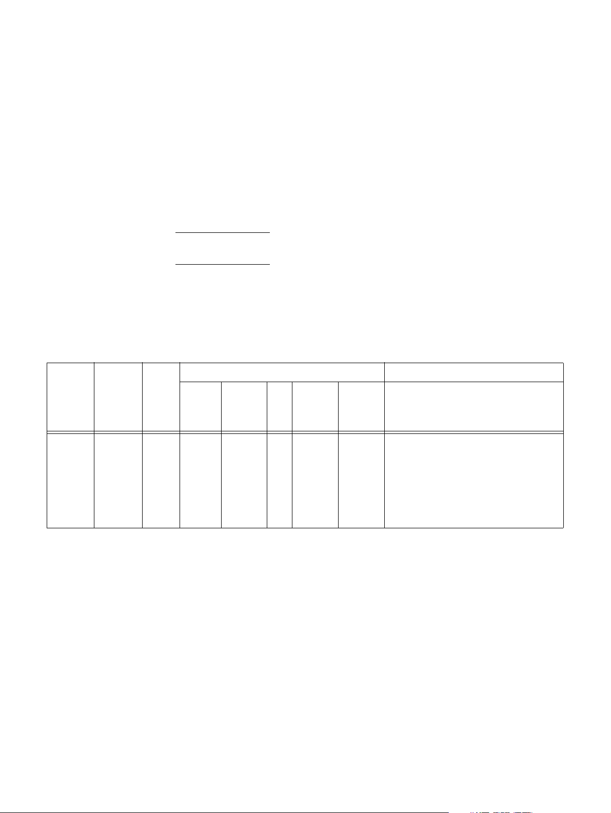
The front of the File/Unified VNX8000 platform 2U Data Mover enclosure (DME) contains
two enclosure status LEDs (power and fault), as shown in Figure 10.
Note: Figure 10 is a graphical representation of the File/Unified VNX8000 platform 2U
Data Mover enclosure with four power supply/cooling (fan) modules and two CPU
modules installed.
Data Mover enclosure
fault LED
AC
AC
Data Mover enclosure
power LED
AC
Figure 10 Data Mover enclosure status LEDs
Table 6 describes the 2U Data Mover enclosure status (power and fault) LEDs.
Table 6 DME status LEDs
LED Color State Description
Power Blue On Data Mover enclosure is powered up, operating normally
— Off Data Mover enclosure is powered down.
Fault Amber On A replaceable component failed within the enclosure.
AC
CNS-001667
— Off Data Mover enclosure operating normally.
24 EMC VNX8000 Hardware Information Guide
Note: When the enclosure fault LED is amber, look for the
replaceable component within the enclosure that is causing
the fault. Refer to the other status LED definitions in this
section to determine which replaceable component failed.
Page 25
System component description
CPU
The CPU modules in the DME contain the power, fault, and unsafe-to-remove LEDs.
Figure 11 shows the CPU LEDs.
CPU fault LED
CPU power LED
AC
AC
AC
CPU unsafe to
remove LED
Figure 11 CPU LEDs
Table 7 describes the CPU LEDs.
Table 7 CPU LEDs
LED Color State Description
Power Green On Data Mover is powered up and all components in the Data
Mover are operating properly.
— Off Data Mover is powered down.
Fault Amber On Data Mover has faulted.
AC
CNS-001669
Blinking Data Mover goes through six stages of power up:
1. Executes a BIOS check, blinking once every 4 seconds
2. Executes a POST check, blinking once every second
3. Loads the operating system, blinking four times a second
Blue
(see
Note)
Blinking 4. Operating system loaded, blinking once every 4 seconds
5. Operating system starting drivers, blinking once every
second
6. Operating system drivers operating, blinking four times a
second
— Off Data Mover operating normally.
Unsafe to
White On Data Mover is unsafe to remove.
remove
— Off Data Mover is safe to remove.
Note: The fault LED changes color from amber to blue when the operating system is loading, see
step 4 in the description.
EMC VNX8000 Hardware Information Guide 25
Page 26
System component description
Power supply/cooling (fan) module LED
The power supply/cooling (fan) modules have status LED on the front. Figure 12 shows
the LEDs for the power supply/cooling (fan) modules.
Power supply/
cooling (fan) power/fault LED
VNX8000 rear view
AC
AC
AC
AC
CNS-001673
Figure 12 Power supply/cooling (fan) module LED
Table 8 describes the power supply/cooling (fan) LED.
Table 8 Power supply/cooling (fan) module LED
LED Color State Description
Power/Fault Green On Normal (no faults detected)
Amber Blinking Power supplied but external fault detected
Amber On No power
As previously described, a Block VNX8000 platform is made up of a 4U SPE while the
File/Unified VNX8000 platform is made up of a 4U SPE, two 1U Control Stations (one
optional), two SPSs, and two to four 2U DMEs. The following sections will describe the
rear view of the VNX8000 platform components as previously shown in Figure 2 on
page 8.
SPS rear view
In the VNX8000 platform, a 2.2-kilowatt Lithium-ion 2U dual standby power supply (SPS)
is used to maintain power to the VNX8000 platform SPE and the Vault DAE during a power
loss.
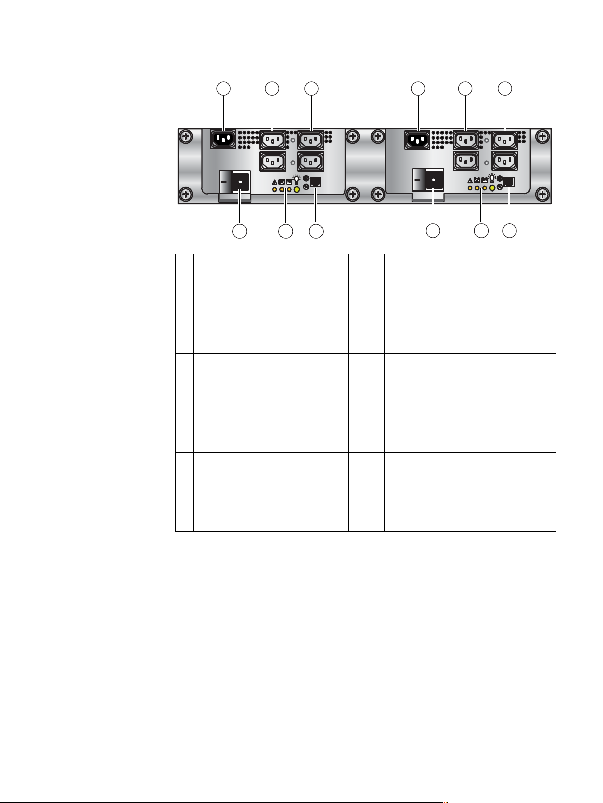
Figure 13 on page 27 shows an example of the rear view of a 2U dual SPS.
26 EMC VNX8000 Hardware Information Guide
Page 27
System component description
1 2 3 4 5 6
VNX-000567
1012 11
1 SPS B AC power in (recessed plug) 7 SPS A RJ-12 connector to the SP A
management (RJ-12) connector or to the
LCC B RJ-12 connector; for more
information, see “SPS RJ-12 connector” on
page 30
2 SPS B power out socket to the SP B
power supply on the SPE or to the LCC
B power supply on the Vault DAE
3 SPS B power out socket to the SP A
power supply on the SPE or to the LCC
A power supply on the Vault DAE
4 SPS A AC power in (recessed plug) 10 SPS B RJ-12 connector to the SP B
5 SPS A power out socket to the SP B
power supply on the SPE or to the LCC
B power supply on the Vault DAE
6 SPS A power out socket to the SP A
power supply on the SPE or to the LCC
A power supply on the Vault DAE
8 Four SPS A LEDs (for more information, see
“SPS LEDs” on page 29)
9 SPS A power on/off rocker switch
management (RJ-12) connector or to the
LCC A RJ-12 connector; for more
information, see “SPS RJ-12 connector” on
page 30
11 Four SPS B LEDs (for more information, see
“SPS LEDs” on page 29)
12 SPS B power on/off rocker switch
79 8
Figure 13 Example of 2U dual SPS B and A viewing from left to right (rear view)
SPS failure functionality
If AC power fails, the SPS provides backup power until the SP has flushed its write cache
data to the DAE disks. The SP then shuts off SPS power. If the cache flush has not
completed within 300 seconds—more than enough time to flush a full cache—or if the SP
has failed, then the SPS shuts down to prevent a deep discharge. If no AC input power is
available and the SPS is shut down, all the status LEDs will be off.
The output voltage, when the SPS is in the On-Line state, is a straight pass-through of the
AC voltage from inlet to outlets. When in the On-Battery state, the output voltage shall be
at an DC level within the specified limits (see the SPS battery LED in Table 11 on page 35).
When power returns, the SPS starts recharging the DC battery. It might reach a state of full
EMC VNX8000 Hardware Information Guide 27
Page 28

System component description
IMPORTANT
Two SPSs for an SPE
charge relatively quickly. If power remains off for a long period—days or weeks—the DC
battery might require more time to charge fully.
2
The storage processor will not use the
write cache unless it detects at least one fully charged SPS.
A faulted or not fully charged SPS disables the write caching.
The additional SPS in the dual SPS is added for redundancy. When only one SPS is used,
the AC line out connectors for the SPS provide AC voltage to both SP A and SP B.
It is important to cable each SPS so that it connects completely to either the A side or the
B side. For example, if you are looking at the SPSs from the rear, they should be
configured as:
◆ SPS A (rear, right side)—Power-out and sense (management) cables connected to the
SP A power supply.
◆ SPS B (rear, left side)—Power-out and sense (management) cables connected to the
SP B power supply.
Two SPSs for a Vault DAE
The additional SPS in the dual SPS is added for redundancy. When only one SPS is used,
the AC line out connectors for the SPS provide AC voltage to both LCC A and LCC B.
It is important to cable each SPS so that it connects completely to either the A side or the
B side. For example, if you are looking at the SPSs from the rear, they should be
configured as:
◆ SPS A (rear, right side)—Power-out and sense (management) cables connected to the
LCC A power supply.
◆ SPS B (rear, left side)—Power-out and sense (management) cables connected to the
LCC B power supply.
Note: If an SPS is cabled with the SPS sense (management) cable going to the power
supply on LCC A and the power-out cable going to the power supply on LCC B (or vice
versa), an error condition will occur when the SPS is tested or when it is charging.
2. After a full power outage, an SPS typically requires 45 minutes or a maximum of 75 minutes to
charge. To charge the SPS after being off-line usually requires at least 6 hours.
28 EMC VNX8000 Hardware Information Guide
Page 29
SPS LEDs
System component description
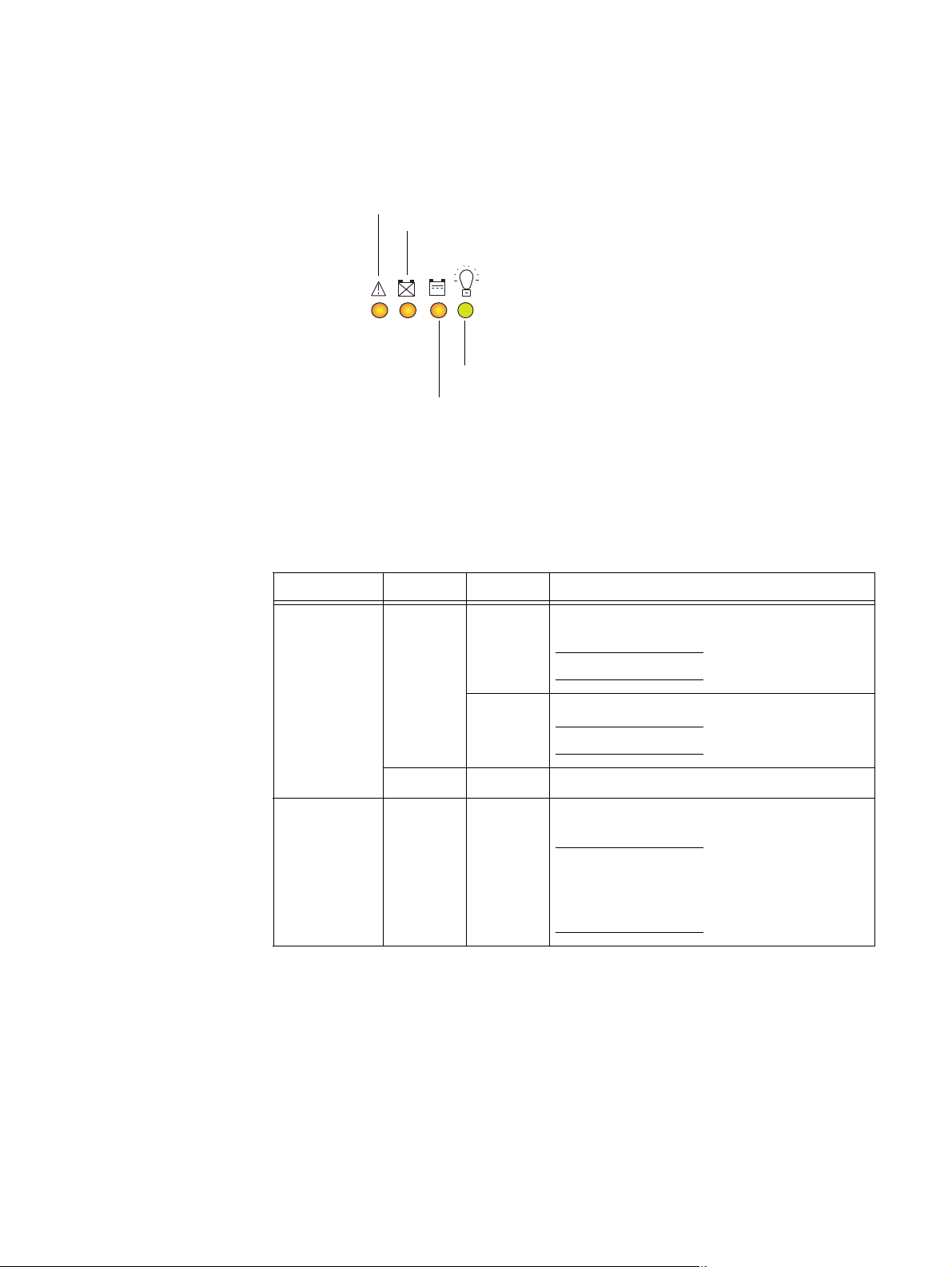
Figure 14 shows the LEDs located on each SPS (A and B)
SPS internal fault
No battery
On-line power
On battery
VNX-000568
Figure 14 SPS LEDs
Table 9 describes the rear panel SPS LEDs.
Table 9 SPS LEDs description
Led Color State Description
On-line power Green On SPS ready and operating normally; battery fully
charged
Note: Off when any amber LED is on.
Blinking On/battery charging
Note: Off when any amber LED is on.
— Off Off/disconnected
On battery Amber On AC line power is no longer available and the SPS is
supplying DC output power from the battery.
Note: When battery power comes on, and no other
online SPS is connected to the SP, the system writes
all cached data to disk, and the event log records
the event.
EMC VNX8000 Hardware Information Guide 29
Page 30
System component description
Table 9 SPS LEDs description (continued)
Led Color State Description
SPS no battery Amber On SPS battery is not fully charged and might not be
able to serve its cache flushing function. With the
battery in this state, and no other online SPS
connected to the SP, the system disables write
caching, and writes any modified pages to the disk
first.
Replace the SPS as soon as possible.
SPS RJ-12 connector
SPS internal
fault
Note: When the SPS powers up, all the LEDs go through a test sequence. They will first turn on and
then turn off beginning with the SPS power on LED (green) ending with the SPS fault LED (amber).
Each LED will light for one second and then turn off. After this sequence, normal LED operation
begins. If the AC line voltage is out-of-specification at power up, no LEDs will light until the AC line
voltage is within specification.
Amber On The SPS has an internal fault. The SPS might still be
able to run online, but write caching cannot occur.
Replace the SPS as soon as possible.
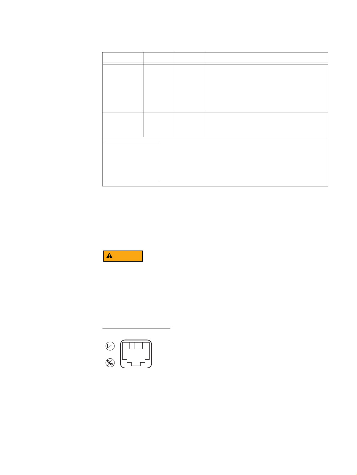
Figure 15 shows the SPS (RJ-12 or modular jack) management port (labeled with two
symbols; one depicting a telephone handset with a line through it and the other depicting
a rectangle with a line through it). Both symbols mean that you cannot connect telephone
type circuits to this connector (see the following WARNING). This port connects the SPS (A
and B) to the SP (A and B) RJ-12 ports or to the LCC (A and B) RJ-12 ports, respectively.
The SPS (RJ-12) port is a LAN port not a WAN port. LAN ports contain safety extra-low
voltage (SELV) circuits, and WAN ports contain telephone-network voltage (TNV) circuits.
An RJ-45 (or TNV-type) looks the same as the RJ-12 except for two very important
differences. An RJ-45 is an 8-wire modular jack. The RJ-12 is a six-wire modular jack. The
RJ-45 plugs and jacks are wider than their RJ-12 counterparts - 7/16" vs 3/8". An RJ-45
plug won't fit into an R-J12 jack. But an RJ-12 plug will fit into an RJ-45 jack. Use caution
when connecting cables. To avoid electric shock, do not attempt to connect TNV circuits
to SELV circuits.
VNX-000626
Figure 15 SPS RJ-12 port
30 EMC VNX8000 Hardware Information Guide
Page 31

System component description
Table 10 lists the SPS (RJ-12) pin signals used on the connector.
Table 10 SPS (RJ-12) connector pinout
RJ-12 pin Signal name Description
1 Ground Signal reference
2 Enabled_out SPS is enabled and ready for On-Battery operation when
needed.
3 AC_fail_out AC line fallen out-of-spec.
4 Any_fault_out Fault state exists within the SPS.
5 SPS_TX Transmit signal out of SPS to host processor
6 SPS_RX Receive signal into SPS from host processor
RJ-12 modular jack to micro DB-9 cable
The cable connecting the SPS to the SP management module is an RJ-12 to micro DB-9
cable (plug). It has an RJ-12 connector (SPS side) on one end and a micro DB-9 connector
(SP management module side) on the other end. Figure 16 shows an example of an SPS to
SP management module cable.
DB-9
Figure 16 Example of SP management module (micro DB-9) SPS (RJ-12) cable
RJ-12
VNX-000283
RJ-12 modular jack to RJ-12 modular jack cable
The cable connecting the SPS to the LCC is an RJ-12 to RJ-12 connector. It has an RJ-12
connector (SPS side) on one end and a RJ-12 connector (LCC side) on the other end.
Figure 17 shows an example of an SPS to LCC cable.
RJ-12RJ-12
VNX-000569
Figure 17 Example of LCC (RJ-12) to SPS (RJ-12) cable
EMC VNX8000 Hardware Information Guide 31
Page 32

System component description
SPE rear view
Figure 18 on page 33 shows an example of the rear of the 4U SPE. The following modules,
connectors, status LEDs, and latch handles are described:
◆ Power supply, four (two for each SP)
• Four power in recessed connectors (plugs); two for each SP
• One power supply latch handle
◆ SP B (top of chassis) and SP A (bottom of chassis)
• Eleven PCI Gen 3 I/O module slots (A0 – A10 and B0 – B10) featuring the following
SP I/O module types:
– Four-port 8-Gb/s FC optical (running at 2, 4, or 8 Gb/s); labeled 8 GbE Fibre on
the latch handle
– Four-port 16-Gb/s FC optical (running at 4, 8, or 16 Gb/s); labeled 16 GbE Fibre
v1 on the latch handle
– Four-port 1-Gb/s Base-T iSCSI I/O module; labeled 1 GbE iSCSI/TOE on the
latch handle
– Two-port 10-Gb/s optical or active Twinax5; labeled 10 GbE v3 on the latch
handle
– Two-port 10-Gb/s RJ45 Base-T iSCSI/IP; labeled 10 GbE Base-T on the latch
handle
– Two-port 10-Gb/s Fibre Channel over Ethernet (FCoE); labeled 10 GbE/FCoE on
the latch handle
– f.) Four-port 6-Gb/s SAS; labeled 6 Gb SAS v3 with an e
3
inside a lock symbol
on the latch handle
• Two management modules (one per SP) featuring:
– Two (RJ-45) LAN connectors (labeled with a network management symbol and a
wrench symbol)
– Two (micro DB-9) RS-232/EIA connectors (labeled with a battery symbol and a
wrench symbol)
–One USB port (not used)
3. The e inside the lock symbol indicates that the I/O module supports encryption.
32 EMC VNX8000 Hardware Information Guide
Page 33

System component description
3
4
2
1
123
0
123
0
7
1 SP B power supply (power in) recessed
connector (plug) from SPS B
2 SP B power supply (power in) recessed
connector (plug) from SPS A
3 SP B (management module) showing two
RJ-45 (management and service laptop)
connectors labeled with a network
management symbol and a wrench
symbol, respectively (for a closer view, see
“Storage processor management module”
on page 34)
5
0123
0123
123
0
123
0
0123
0123
VNX-000800
6
5 SP B four-port 6-Gb/s SAS I/O module in
slot B5 (for a closer view, see “Four-port
6-Gb/s SAS I/O module” on page 61)
6 SP A I/O module filler panel
7 SP A (management module) showing two
RS-232/EIA (micro DB-9) connectors
(labeled with a battery symbol and a
wrench symbol, respectively) (for a closer
view, see “Storage processor management
module” on page 34)
4 SP B four-port 8-Gb/s FC I/O module in
slot A2 (for a closer view, see “Four-port
8-Gb/s FC I/O module” on page 48)
Figure 18 Example of SP components (rear view)
Storage processor AC power supply module
The storage processor (SP) power supply module is located on the left side of each SP
when viewed from the rear (see locations 1 and 2 in Figure 18). On the front (“Storage
processor (SP) AC power supply module” on page 18) of the power supply, each power
supply includes three status LEDs (AC, DC, and fault (labeled with an upside-down
exclamation point, !). A latch on the power supply locks it into place to ensure proper
connection.
Do not
remove the SP power supply module while the SP is plugged in. Power supply
module removal for more than a few minutes can cause the SP to shut down due to lack of
cooling.
EMC VNX8000 Hardware Information Guide 33
Page 34

System component description
Storage processor management module
The storage processor (SP) management module provides the management connections
via one 10/100/1000 Ethernet (RJ-45) port. Another RJ-45 port is available to support a
service laptop connection. The SP management module includes two RS-232/EIA 232
(DB-9) serial socket connectors (one for service laptop connection and the other for an
SPS connection), a USB port (not used), and several LEDs (Figure 19).
1
7
6
5
1 Power/fault LED 5 DB-9 serial console socket connector
2 SP management module push button latch
handle
3 RJ-45 Ethernet port (management) 7 RJ-45 Ethernet port (service laptop)
2
3
4
VNX-000583
(SPS); not used
6 USB port; not used
4 DB-9 serial console socket connector
(service laptop)
Figure 19 SP management module
Storage processor management module Ethernet (RJ-45) ports
The VNX8000 platform storage processor (SP) management module comes with two
integrated dual-port Ethernet ports (labeled with a symbol depicting a wrench and the
other depicting network management) on the rear of the management module. The SP
management port provides an interface for connecting a 10-, 100-, or 1000-Mb/s cable to
the LAN providing full-duplex (FDX) capability, which enables simultaneous transmission
and reception of data.
To access the SP management port, connect a Category 3, 4, 5, 5E, or 6 unshielded
twisted-pair (UTP) cable to this RJ-45 modular jack connector on the back of the SP
management module, as described in Table 13 on page 38.
Since the 1U Control Station and the management module have the same type of
management (RJ-45) ports, “Control Station Ethernet (RJ-45) ports” on page 38 provides
detailed information about the SP management module ports, connector, and adapter.
34 EMC VNX8000 Hardware Information Guide
Page 35

Storage processor management module LEDs
t
t
Figure 20 shows the LEDs and Table 11 describes them.
Power/Fault LED
Management por
(Activity LED)
Management por
(Link LED)
Service laptop port
(Link LED)
Service laptop port
(Activity LED)
System component description
VNX-000584
Figure 20 SP management module LEDs
Table 11 SP management module LEDs
LED Color State Description
Power/Fault Green On SP management module is powered up.
Amber On SP management module has faulted.
Note: LED is always illuminated at powerup, until it is
initialized.
— Off SP management module is powered down.
Link (each
port has
one)
Activity
(each port
has one)
SP management module serial console (DB-9) socket connector
Green On Network connection
— Off No network connection
Amber Blinking Transmit/receive activity
— Off No network activity
The back of the VNX8000 platform SP management module includes two standard serial
console Electronics Industries Association (EIA) RS-232 interface (DB-9) socket
connectors (one labeled with a symbol depicting a wrench on the right and the other
depicting a battery on the left). Notice the orientation of the pins (Figure 21).
EMC VNX8000 Hardware Information Guide 35
Page 36

System component description
5
Pin 1
9
6
9
6
5
Pin 1
Figure 21 SP management module serial console (DB-9) socket connectors
Table 12 lists the SP management module Ethernet (DB-9) pin signals used on the
connectors.
Note: The pin designations shown in Figure 21 are for reference only.
Table 12 SP management module (DB-9) socket connector pinout
DB-9 Pin Signal Description
1 CD Carrier detect
2 TXD Transmitted data
3 RXD Received data
4 DTR Data terminal ready
5GNDGround
6DSRData set ready
7 RTS Request to send
8 CTS Clear to send
9 RI Ring indicator (not used)
Storage processor null modem (micro DB-9 to DB-9 serial) cable — The cable connecting
the SP management module to the PC or service laptop is a micro DB-9 cable (plug) to
serial DB-9 (socket). It has a micro DB-9 plug (SP side) on one end and a serial DB-9
socket (PC or service laptop side) on the other end. Figure 22 shows an example of an SP
management module to PC (service laptop) cable.
VNX-000093
Figure 22 Example of SP null modem (micro DB-9) to serial (DB-9) cable
36 EMC VNX8000 Hardware Information Guide
Page 37

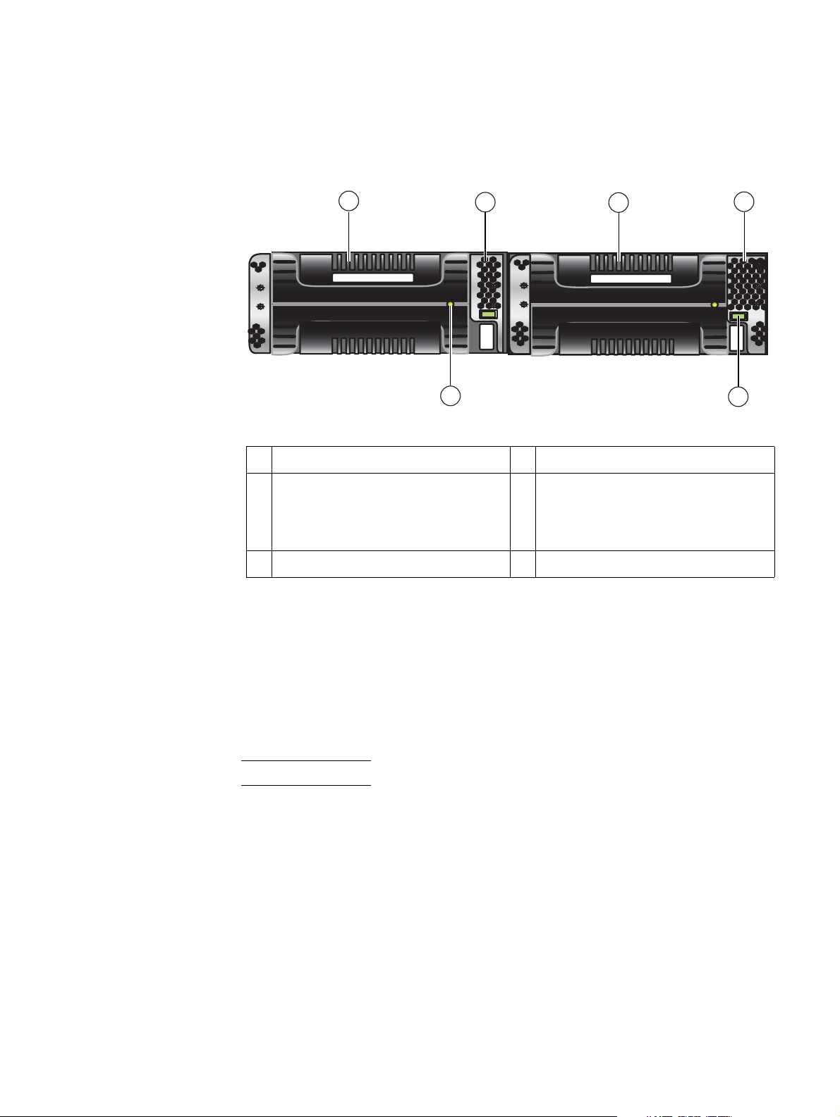
Control Station rear view
System component description
On the rear, viewing from left to right, the File/Unified VNX8000 platform Control Station
includes the following components:
◆ AC power in connector
◆ Five (RJ-45) connectors (labeled A, CS, B, and two MGMT [one not used, see location 2
in Figure 23])
Note: The RJ-45 connectors (labeled CS and A, respectively) are integrated into the
rear of the 1U Control Station while the RJ-45 connectors (labeled B and MGMT,
respectively) are on a PCI-e card in the expansion slot on the rear of the Control
Station. The fifth RJ-45 connector (labeled MGMT) is located to the left of the RJ-45
connector labeled CS. Newer CS models have a dust cover in this port.
◆ One (DB-9 plug) serial (RS-232/EIA-232) connector
◆ One (DB-9 plug) modem (RS-232/EIA-232) connector
◆ One (DB-15) video (VGA socket) connector—not used
◆ Four USB 2.0 connectors—not used
Figure 23 on page 37 shows the orientation of these components.
2
MGMT
IOIO
10
1
1 AC power in connector 6 RJ-45 Ethernet port (labeled MGMT)
2 RJ-45 Ethernet port (labeled MGMT), not
7 DB-9 serial console plug connector
used; newer CS models have a dust cap in
this port
3 RJ-45 Ethernet port (labeled CS
1
)
8 Four USB 2.0 connectors (not used)
Note: The CS label is located below the
USB ports.
4 RJ-45 Ethernet port (labeled A)
9 DB-15 Video (VGA) socket connector (not
Note: The A label is located below the USB
ports.
4 51 6
3
2
A
CS
89
used)
B MGMT
MGMT
B
7
VNX-000525
5 RJ-45 Ethernet port (labeled B) 10 DB-9 modem plug connector
1. The CS port uses an IPMI (Intelligent Platform Management Interface) cable to connect to a standby (optional)
Control Station (CS1).
Figure 23 Example of a VNX8000 Control Station (rear view)
EMC VNX8000 Hardware Information Guide 37
Page 38

System component description
Control Station Input/output ports and connectors
The File/Unified VNX8000 platform 1U Control Station supports the following I/O ports on
the rear of the 1U Control Station:
◆ Five Ethernet (RJ-45) ports (one not used [labeled MGMT], see location 2 in Figure 23
on page 37)
◆ One serial console (DB-9 plug) connector
◆ One modem (DB-9 plug) connector
To avoid electric shock, do not connect safety extra-low voltage (SELV) circuits to
telephone-network voltage (TNV) circuits. LAN ports contain SELV circuits, and WAN ports
contain TNV circuits. Some LAN and WAN ports both use RJ-45 connectors. Use caution
when connecting cables.
Control Station Ethernet (RJ-45) ports
The File/Unified VNX8000 platform 1U Control Station comes with two integrated
dual-port Ethernet ports (labeled CS and A, respectively) and two Peripheral Component
Interconnect Express (PCI-E)
MGMT, respectively) in an expansion slot on the rear of the 1U Control Station.
4
low profile card dual-port Ethernet ports (labeled B and
Note: A fifth RJ-45 connector (labeled MGMT) is located to the left of the RJ-45 connected
labeled CS. This connector is not used at this time.
These ports (Figure 24 on page 39) provide an interface for connecting to 10-, 100-, or
1000-Mb/s networks and provide full-duplex (FDX) capability, which enables
simultaneous transmission and reception of data on the Ethernet local-area network
(LAN).
To access the Ethernet ports, connect a Category 3, 4, 5, 5E, or 6 unshielded twisted-pair
(UTP) cable to the RJ-45 connectors on the back of the 1U Control Station, as described in
Table 13.
Table 13 Ethernet cabling guidelines
Type Description
10BASE-T EIA Categories 3, 4, or 5 UTP (2 or 4 pairs) up to 328 ft (100 m)
100BASE-TX EIA Category 5 UTP (2 pairs) up to 328 ft (100 m)
1000BASE-T EIA Category 6 (recommended), Category 5E or 5 UTP (2 pairs) up to 328 ft
(100 m)
4. PCI Express is used in consumer, server, and industrial applications, as a motherboard-level
interconnect (to link motherboard-mounted peripherals) and as an expansion card interface for
add-in boards.
38 EMC VNX8000 Hardware Information Guide
Page 39

System component description
Control Station Ethernet (RJ-45) port and connector (adapter)
Figure 24 shows an example of the Ethernet RJ-45 port and cable connector.
8 7 6 5 4 3 2 1
CNS-001749
Figure 24 Control Station Ethernet (RJ-45) port and connector (adapter)
Table 14 lists the Control Station Ethernet (RJ-45) pin signals used on the connector.
Table 14 Control Station Ethernet (RJ-45) port and connector pinout
RJ-45 pin Signal Description
1 BI_DA+ Bidirectional pair A, +
2 BI_DA- Bidirectional pair A, -
3 BI_DB+ Bidirectional pair B, +
4 BI_DC+ Bidirectional pair C, +
5 BI_DC- Bidirectional pair C, -
6 BI_DB- Bidirectional pair B, -
7 BI_DD+ Bidirectional pair D, +
8 BI_DD- Bidirectional pair D, -
Control Station Ethernet (RJ-45) port LEDs
The Control Station (RJ-45) has two LEDs—a green LED to the left of the connector and a
bi-color (green/amber) LED to the right of the connector—that indicates the link/activity
and speed of the 1U Control Station (RJ-45) ports, respectively (Figure 25).
21
CNS-001748
Figure 25 Control Station Ethernet (RJ-45) port LEDs
EMC VNX8000 Hardware Information Guide 39
Page 40

System component description
Table 15 describes the link/activity and connection speed associated with the Control
Station (RJ-45) port LEDs.
Table 15 Control Station RJ-45 port LEDs
Led Color State Description
Left,
Green On Network/link connection
link/activity
(see location 1)
Green Blinking Transmit/receive activity
— Off No network/link connection
Right, link
Green On 100-Mb/s connection
speed
(see location 2)
Amber On 1000-Mb/s (or 1-Gb/s) connection
— Off 10-Mb/s connection (if left LED is on or blinking)
Ethernet cable extensions for the Control Station B and MGMT ports
Each File/Unified VNX8000 platform 1U Control Station comes with two modular Ethernet
cable extensions (or patch cords) for the RJ-45 ports (labeled on the CS as B and MGMT,
respectively). These cables (Figure 26) allow you to extend the length of the Ethernet
cables from the CS 0, port B to Data Mover enclosure 0, management module B, port 1
and CS 0, MGMT port to the public LAN.
If your File/Unified VNX8000 platform includes a second optional 1U Control Station
(CS 1), another set of Ethernet cable extensions for the RJ-45 ports is provided. These
cables allow you to extend the length of the Ethernet cables from the CS 1, port B to Data
Mover enclosure 0, management module B, port 2 and CS 1, MGMT port to the public LAN.
Each cable includes a corresponding label clip to assist you during system cabling.
Note: If you received the File/Unified VNX8000 platform already installed in a cabinet rack
with all of the File/Unified VNX8000 platform components, all the cabling has already
been installed.
VNX-000564
Figure 26 Example of an Ethernet extension (modular plug to modular jack) cable
Control Station serial console (DB-9) plug connector
The back of the File/Unified VNX8000 platform system 1U Control Station includes a
standard serial console Electronics Industries Association (EIA) RS-232 interface (DB-9)
plug connector. Notice the orientation of the pins (Figure 27).
Pin 1
Figure 27 Control Station serial console (DB-9) plug connector
6 9
5
VNX-000526
40 EMC VNX8000 Hardware Information Guide
Page 41

System component description
Note: The pin designations shown in Figure 27 on page 40 are for reference only.
Table 16 lists the 1U Control Station Ethernet (DB-9) pin signals used on the connector.
Table 16 Control Station (DB-9) plug connector pinout
DB-9 Pin Signal Description
1 CD Carrier detect
2RXDReceived data
3 TXD Transmitted data
4 DTR Data terminal ready
5GNDGround
6DSRData set ready
7 RTS Request to send
8 CTS Clear to send
9 RI Ring indicator (not used)
Control Station modem (DB-9) plug connector
The back of the File/Unified VNX8000 platform 1U Control Station includes a standard
modem serial interface (DB-9) plug connector (labeled with a telephone handset icon and
the numbers 1 0 1 0 on the left). Notice the orientation of the pins (Figure 28).
1 0 1 0
Pin 1
6 9
5
VNX-000527
Figure 28 Control Station modem (DB-9) plug connector
Note: The pin designations shown in Figure 28 are for reference only.
Table 17 lists the 1U Control Station Ethernet (DB-9) pin signals used on the connector.
Table 17 Control Station modem (DB-9) plug connector pinout
DB-9 Pin Signal Description
1 CD Carrier detect
2 RXD Received data
3 TXD Transmitted data
4 DTR Data terminal ready
5GNDGround
6DSRData set ready
EMC VNX8000 Hardware Information Guide 41
Page 42

System component description
Table 17 Control Station modem (DB-9) plug connector pinout
DB-9 Pin Signal Description
7 RTS Request to send
8 CTS Clear to send
9 RI Ring indicator (not used)
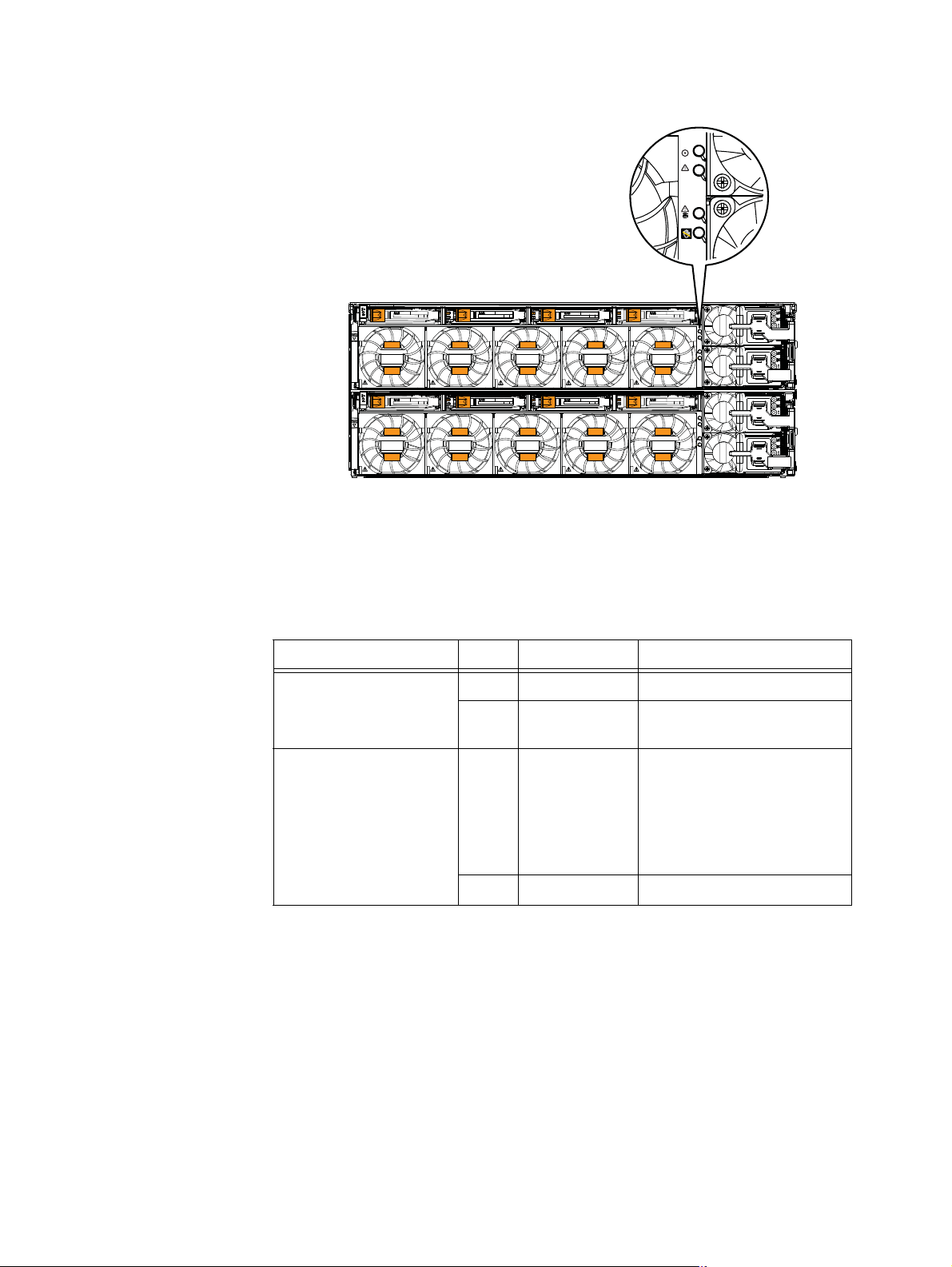
Data Mover enclosure rear view
The rear of the File/Unified VNX8000 platform Data Mover enclosure (DME) does not
contain any LEDs (Figure 29). Only the Data Mover management module and the I/O
modules have LEDs.
Note: Figure 29 is a graphical representation of the rear view of a File/Unified VNX8000
platform with a DME having two Data Movers (each Data Mover shows one management
module, one four-port 8-Gb/s FC I/O module, and four filler panel modules).
23
23
23
23
1
1
0
0
2
1
VNX-000600
123
0
23
1
0
23
1
0
23
1
0
23
1
0
1
123
0
1
0
0
34
1 Data Mover enclosure 3 Four-port 8-Gb/s FC I/O module
2 Filler panel module 4 Data Mover management module
Figure 29 Example of a DME (rear view)
Data Mover management module
The Data Mover management module provides the management connections via three
10/100/1000 Ethernet (RJ-45) ports. The Data Mover management module also includes
one RS-232 (EIA) DB-9 serial socket connector for service laptop connection and several
LEDs (Figure 30 on page 43).
42 EMC VNX8000 Hardware Information Guide
Page 43

System component description
2
0
1
#
1
2
3
4
5
6
7
CNS-001754
1 Power/fault LED 5 DB-9 serial console socket connector
2 Data Mover management module push
button latch handle
3 RJ-45 Ethernet port (labeled 1) 7 RJ-45 Ethernet port (labeled 2)
4 Data Mover enclosure ID numeric display
Figure 30 Example of a Data Mover management module
6 RJ-45 Ethernet port (labeled 0)
Data Mover management module Ethernet (RJ-45) ports
The File/Unified VNX8000 platform Data Mover management module comes with three
integrated dual-port Ethernet ports (labeled 0, 1, and 2) on the rear of the Data Mover
management module. These ports provide an interface for connecting to 10-, 100-, or
1000-Mb/s networks and provide full-duplex (FDX) capability, which enables
simultaneous transmission and reception of data.
The File/Unified VNX8000 Data Mover management module contains LAN ports. LAN
ports contain safety extra-low voltage (SELV) circuits, and WAN ports contain
telephone-network voltage (TNV) circuits. To avoid electric shock, do not connect TNV
circuits to SELV circuits. Some LAN and WAN ports both use RJ-45 connectors. Use caution
when connecting cables.
To access the Ethernet ports, connect a Category 3, 4, 5, 5E, or 6 unshielded twisted-pair
(UTP) cable to the RJ-45 connector on the back of the management module (Table 13 on
page 38).
Since the Control Station and the management module have the same type of RJ-45 ports,
“Control Station Ethernet (RJ-45) ports” on page 38 provides detailed information about
the management module ports, connector, and adapter.
EMC VNX8000 Hardware Information Guide 43
Page 44

System component description
Data Mover management module LEDs
Figure 31 shows the LEDs and Table 18 on page 44 describes them.
Power/Fault LED
Port 2 (Activity LED)
Port 2 (Link LED)
Port 0 (Link LED)
Port 0 (Activity LED)
2
1
0
#
CNS-001671
Port 1 (Activity LED)
Port 1 (Link LED)
Numeric display
(blade enclosure ID)
Figure 31 Data Mover management module LEDs
Table 18 Data Mover management module LEDs
LED Color State Description
Power/Fault Green On Data Mover management module is powered up.
Amber On Data Mover management module has faulted.
Note: LED is always illuminated at powerup, until it is
initialized.
Link (each
port has one)
Activity (each
port has one)
Numeric
(7-segment)
display for
enclosure ID
Data Mover management module serial console (DB-9) socket connector
The back of the File/Unified VNX8000 platform Data Mover management module includes
a standard serial console Electronics Industries Association (EIA) RS-232 interface (DB-9)
socket connector (labeled with a wrench tool icon on the left). Notice the orientation of
the pins (Figure 32 on page 45).
44 EMC VNX8000 Hardware Information Guide
—OffData Mover management module is powered down.
Green On Network connection
— Off No network connection
Amber Blinking Transmit/receive activity
— Off No network activity
— On Displays the enclosure ID assigned to the Data Mover
enclosure.
Note: Each enclosure is assigned a number at installation.
Page 45

I/O modules
5
9
6
Pin 1
Figure 32 Data Mover management module serial console (DB-9) socket connector
Table 19 lists the Data Mover management module Ethernet (DB-9) pin signals used on
the connector.
Note: The pin designations shown in Figure 32 are for reference only.
Table 19 Data Mover management module (DB-9) socket connector pinout
DB-9 Pin Signal Description
1 CD Carrier detect
2 TXD Transmitted data
3 RXD Received data
4 DTR Data terminal ready
5GNDGround
6DSRData set ready
7 RTS Request to send
8 CTS Clear to send
9 RI Ring indicator (not used)
I/O modules
Several types of I/O modules are supported in the Block, File, and Unified VNX8000. The
SP supports six types of I/O modules (see “Storage processor I/O module types” on
page 47) and the Data Mover supports four types (see “Data Mover I/O module types” on
page 63). In this section, each I/O module description includes the type of port (copper or
optical) as well as a description of the LEDs.
Fibre Channel (FC) ports
The Block, File, and Unified VNX8000 platform SP does not come with built-in optical Fibre
Channel (FC) ports on the rear of each SP (A and B). As a result, the 8-Gb/s Fibre Channel
(FC) I/O module or the 16-Gb/s Fibre Channel (FC) I/O module is used to provide these FC
ports (see “Four-port 8-Gb/s FC I/O module” on page 48 and “Four-port 16-Gb/s FC I/O
module” on page 51, respectively). These ports provide an optical interface for
connecting to the front end.
EMC VNX8000 Hardware Information Guide 45
Page 46

I/O modules
Small form-factor pluggable transceiver modules
The FC ports on the 8-Gb/s FC I/O module support 2-, 4-, and 8-Gb/s Fibre Channels and
on the 16-Gb/s FC I/O module supports 4, 8, and 16-Gb/s Fibre Channels using a small
form-factor pluggable plus (SFP+) transceiver module. The SFP+ transceiver modules
connect to Lucent Connector (LC) type optical fibre cables. These SFP+ transceiver
modules are input/output (I/O) devices. These SFP+ modules are hot swappable. This
means that you can install and remove an SFP+ module while the SP is operating.
Figure 33 shows an example of an SFP+ module.
Note: Besides the FC I/O modules, the FCoE and the 10-Gb/s Optical I/O modules also use
SFP modules. Each of these I/O modules use a different type of SFP. Refer to the Parts
Location Guide for more information.
1 Dust plug (protective cap) 3 Send or transmit (TX) optical bore
2 Bale clasp latch 4 Receive (RX) optical bore
Figure 33 Example of an SFP+ module
Lucent Connector type interface
The Lucent Connector (LC) type interface was developed by Lucent Technologies (hence,
Lucent Connector). It uses a push-pull mechanism. LC connectors are normally held
together in a multimode duplex configuration with a plastic clip. These cables are usually
colored orange for OM2 multimode optical fiber type cables and aqua for OM3 multimode
optical fiber type cables. These cables have the duplex connectors encased in a gray
plastic covering. To determine the send or transmit (TX) and receive (RX) ferrules
(connector ends), these cables will show a letter and numeral (for example A1 and A2 for
the TX and RX, respectively) or a white and yellow rubber gasket (jacket) for the send or
transmit (TX) and receive (RX) ends (Figure 34 on page 47).
4
3
2
1
CNS-001090
46 EMC VNX8000 Hardware Information Guide
Page 47

I/O modules
IMPORTANT
A
2
A
1
1
3
2
4
1 Orange cable 3 Rubber gasket (jacket), receive (RX)
2 Rubber gasket (jacket), send or
transmit (TX)
Figure 34 Example of LC-type connectors
Storage processor I/O module types
Seven I/O module types are supported by the Block, File, and Unified VNX8000 platform
SP. However, only ten slots are supported per SP (A0 – A10 and B0 – B10) in the
File/Unified VNX8000 platform SPE. For more information, refer to the
Processor I/O modules and SFPs
https://mydocs.emc.com/VNX/ and go to VNX tasks, then select Add VNX hardware. Next,
follow the steps in the wizard.
When adding new I/O modules, always install I/O modules in pairs—one module in SP A
and one module in SP B. Both SPs must have the same type of I/O modules in the same
slots.
CNS-001102
4 Ferrule (connector end to SFP+ module)
Adding Storage
document available online at
I/O module slots
Slots A8 and B8 will contain a fibre Channel (FC) I/O module for Data Mover connections
to the first four system Data Movers. Additionally, slots A2 and B2 in each SP will contain
another FC I/O module, if the eight Data Mover option for the File/Unified VNX8000
platform is ordered. Slots A5, A10 and B5, B10 will always contain a 6-Gb/s SAS I/O
module in the SPE. Slots A4, A6 and B4, B6 in the SPE will contain another 6-Gb/s SAS I/O
module if the 16-bus option for the File/Unified VNX8000 platform is ordered. The other
available slots can contain any type of I/O module that is supported for the storage
system, within the supported I/O module limits of the supported I/O modules per SP in
the SPE. For more information, refer to the
Adding Storage Processor I/O modules and
EMC VNX8000 Hardware Information Guide 47
Page 48

I/O modules
IMPORTANT
SFPs
document available online at https://mydocs.emc.com/VNX/ and go to VNX tasks,
then select Add VNX hardware. Next, follow the steps in the wizard.
EMC requires that an 8-bus File/Unified VNX8000 platform with greater than four Data
Movers be installed with four standard I/O modules per SP, leaving space for seven
optional I/O modules per SP. Then, in a 16-bus File/Unified VNX8000 platform with
greater than four Data Movers, EMC requires six standard I/O modules per SP, leaving
space for five optional I/O modules per SP For more information, refer to the
Storage Processor I/O modules and SFPs
document.
Adding
The following I/O modules are supported:
◆ “Four-port 8-Gb/s FC I/O module” on this page
◆ “Four-port 16-Gb/s FC I/O module” on page 51
◆ “Four-port 1-Gb/s copper iSCSI I/O module” on page 53
◆ “Two-port 10-Gb/s optical or active Twinax Fibre Channel over Ethernet (FCoE) I/O
module” on page 55
◆ “Two-port 10-Gb/s RJ-45 Base-T iSCSI/IP I/O module” on page 57
◆ “Two-port 10-Gb/s optical I/O module” on page 59
◆ “Four-port 6-Gb/s SAS I/O module” on page 61
Four-port 8-Gb/s FC I/O module
The four-port 8-Gb/s FC I/O module (labeled 8 GbE Fibre on the latch handle) comes with
four optical (fibre) ports, one power/fault LED, and a link/activity LED for each optical port
(Figure 35 on page 49). This I/O module can interface at speeds of 2, 4, and 8 Gb/s.
The four-port 8-Gb/s FC I/O module uses SFP+ transceiver modules to connect to LC-type
optical fibre cables (“Lucent Connector type interface” on page 46). These SFP+
transceiver modules are input/output (I/O) devices that plug into the FC port of the FC I/O
modules. For more information about these SFP+ transceiver modules, see the “I/O
modules” section on page 45.
48 EMC VNX8000 Hardware Information Guide
Page 49

I/O modules
1
2
3
4
CNS-001752
1 Push button latch handle 3 SFP+ (optical) port (four)
2 Power/fault LED 4 SFP+ link/activity LED
Figure 35 Four-port 8-Gb/s FC I/O module
Note: The 8-Gb/s I/O module uses a specific type of SFP module, ensure you are using the
correct one. Refer to the Parts Location guide for more information.
EMC VNX8000 Hardware Information Guide 49
Page 50

I/O modules
Four-port 8-Gb/s FC I/O module LEDs
The four-port 8-Gb/s Fibre Channel (FC) I/O module has two different types of status LEDs.
Figure 36 shows the LEDs and Table 20 describes them.
Power/fault
LED
Link/Activity
LED
Link/Activity
LED
Link/Activity
LED
Link/Activity
LED
CNS-001670
Figure 36 Four-port 8-Gb/s FC I/O module LEDs
Table 20 Four-port 8-Gb/s FC I/O module LEDs
LED Color State Description
Power/Fault Green On I/O module is powered up.
Amber On I/O module has faulted.
— Off I/O module is powered down.
Link/Activity
Green On 2- or 4-Gb link speed (suboptimal speed)
(each port
has one LED)
Blue On 8-Gb/s link speed (maximum speed)
Green or
Blue
Blinking Small form-factor pluggable (SFP+
faulted, unsupported, or optical cable fault.
— Off No network connection
1. Refer to the
VNX8000 Parts Location Guide
for the correct SFP+ part number.
1
) transceiver module
50 EMC VNX8000 Hardware Information Guide
Page 51

Four-port 16-Gb/s FC I/O module
The four-port 16-Gb/s FC I/O module (labeled 16 Gb Fibre v1 on the latch handle) comes
with four optical (fibre) ports, one power/fault LED, and a link/activity LED for each optical
port (Figure 37). This I/O module can interface at speeds of 4, 8, and 16 Gb/s.
I/O modules
1
1 Push button latch handle 3 SFP+ (optical) port (four)
2 Power/fault LED 4 SFP+ link/activity LED
2
3
4
CNS-001752
Figure 37 Four-port 16-Gb/s FC I/O module
The four-port 16-Gb/s FC I/O module uses SFP+ transceiver modules to connect to LC-type
optical fibre cables (“Lucent Connector type interface” on page 46). These SFP+
transceiver modules are input/output (I/O) devices that plug into the FC port of the FC I/O
modules. For more information about these SFP+ transceiver modules, see the “I/O
modules” section on page 45.
Note: The 16-Gb/s I/O module uses a specific type of SFP module, ensure you are using
the correct one. Refer to the Parts Location guide for more information.
EMC VNX8000 Hardware Information Guide 51
Page 52

I/O modules
Four-port 16-Gb/s FC I/O module LEDs
The four-port 16-Gb/s Fibre Channel (FC) I/O module has two different types of status
LEDs. Figure 38 shows the LEDs and Table 2 1 describes them.
Power/fault
LED
Link/Activity
LED
Link/Activity
LED
Link/Activity
LED
Link/Activity
LED
CNS-001670
Figure 38 Four-port 16-Gb/s FC I/O module LEDs
Table 21 Four-port 16-Gb/s FC I/O module LEDs
LED Color State Description
Power/Fault Green On I/O module is powered up.
Amber On I/O module has faulted.
— Off I/O module is powered down.
Link/Activity
Blue On 4-, 8-, or 16-Gb/s link speed (autonegotiates)
(each port
has one LED)
Blue Blinking Small form-factor pluggable (SFP+
faulted, unsupported, or optical cable fault.
— Off No network connection
1. Refer to the
VNX8000 Parts Location Guide
for the correct SFP+ part number.
1
) transceiver module
52 EMC VNX8000 Hardware Information Guide
Page 53

Four-port 1-Gb/s copper iSCSI I/O module
The four-port 1-Gb/s copper iSCSI I/O module (labeled 1 GbE iSCSI/TOE on the latch
handle) comes with four 1-Gb/s copper ports, one power/fault LED, and a link and activity
LED for each port (Figure 39). The copper ports on this I/O module can interface at speeds
up to 1 Gb/s for iSCSI (Internet Small Computer System Interface) networks
1 2
I/O modules
5
.
3
4
5
CNS-001751
1 Push button latch handle 4 RJ-45 link LED
2 Power/fault LED 5 RJ-45 activity LED
3 RJ-45 (copper) port (four)
Figure 39 Four-port 1-Gb/s copper iSCSI I/O module
5. iSCSI is a protocol for sending SCSI packets over TCP/IP networks.
EMC VNX8000 Hardware Information Guide 53
Page 54

I/O modules
Four-port 1-Gb/s copper iSCSI I/O module LEDs
The four-port 1-Gb/s copper iSCSI I/O module has three types of status LEDs. Figure 40
shows the LEDs and Table 22 describes them.
Power/fault
LED
Link LEDs
CNS-001666
Activity LEDs
Figure 40 Four-port 1-Gb/s copper iSCSI I/O module LEDs
Table 22 Four-port 1-Gb/s copper iSCSI I/O module LEDs
LED Color State Description
Power/Fault Green On I/O module is powered up.
Amber On I/O module has faulted.
— Off I/O module is powered down.
Link (each
Green On Network connection
port has
one)
Activity
— Off No network connection
Amber Blinking Transmit/receive activity
(each port
has one)
— Off No activity
54 EMC VNX8000 Hardware Information Guide
Page 55

Two-port 10-Gb/s optical or active Twinax Fibre Channel over Ethernet (FCoE) I/O module
The two-port 10-Gb/s optical or active Twinax6 FCoE I/O module (labeled 10 GbE/FCoE on
the latch handle) comes with two FCoE ports, one power/fault LED, and a link and activity
LED for each port (Figure 41). The ports on this I/O module can interface at speeds up to
10 Gb/s for Fibre Channel over Ethernet networks. The two-port 10-Gb/s FCoE I/O module
uses the SFP+ transceiver module. For part number label location, see the
Location Guide
available online at https://mydocs.emc.com/VNX/ and go to Additional
VNX documentation, and select the related documentation software for the model
desired, then go to VNX Hardware Parts, next select the VNX8000 Parts Guide.
VNX8000 Parts
I/O modules
1
1 Push button latch handle 4 SFP+ link LED (right)
2
1
0
CNS-001756
3
4
5
2 Power/fault LED 5 SFP+ activity LED (left)
3 SFP+ (optical) port (two)
Figure 41 Two-port 10-Gb/s FCoE I/O module
Note: The 10-Gb/s FCoE I/O module uses a specific type of SFP module, ensure you are
using the correct one. Refer to the Parts Location guide for more information.
6. The FCoE I/O module can also use active twinaxial (Twinax) cables. Twinax is a type of cable
similar to coax, but with two inner conductors instead of one. These cables will be supplied in lieu
of the SFP+ transceiver module when so ordered.
EMC VNX8000 Hardware Information Guide 55
Page 56

I/O modules
Two-port 10-Gb/s FCoE I/O module LEDs
The two-port 10-Gb/s FCoE I/O module has three types of status LEDs. Figure 42 shows
the LEDs and Table 23 describes them.
Power/fault LED
1
0
CNS-001672
Link LED
Activity LED
Link LED
Activity LED
Figure 42 Two-port 10-Gb/s FCoE I/O module LEDs
Table 23 two-port 10-Gb/s FCoE I/O module LEDs
LED Color State Description
Power/Fault Green On I/O module is powered up.
Amber On I/O module has faulted.
Link Green On Network connection
Activity Amber Blinking Transmit/receive activity
56 EMC VNX8000 Hardware Information Guide
— Off I/O module is powered down.
— Off No network connection
— Off No activity
Page 57

Two-port 10-Gb/s RJ-45 Base-T iSCSI/IP I/O module
The two-port 10-Gb/s RJ-45 Base-T iSCSI/IP I/O module (labeled 10 GbE Base-T on the
latch handle) comes with two 10-Gb/s Base-T copper ports, one power/fault LED, and a
link and activity LED for each port (Figure 43). The Base-T ports on this I/O module can
interface at speeds of 10 Gb/s for iSCSI (Internet Small Computer System Interface)
networks
Twisted Pair (UTP) or EIA Category 7 fully Shielded Twisted Pair (STP) copper cabling.
7
. The two-port 10-Gb/s Base-T I/O module uses EIA Category 6 or 6a Unshielded
I/O modules
1
10
2
3
4
5
VNXe-000751
1 Push button latch handle 4 Link LED (right)
2 Power/fault LED 5 Activity LED (left)
3 RJ-45 Base-T port (2)
Figure 43 Two-port 10-Gb/s RJ-45 Base-T I/O module
7. iSCSI is a protocol for sending SCSI packets over TCP/IP networks.
EMC VNX8000 Hardware Information Guide 57
Page 58

I/O modules
Two-port 10-Gb/s RJ-45 Base-T I/O module LEDs
The two-port 10-Gb/s RJ-45 Base-T I/O module has three types of status LEDs. Figure 44
shows the LEDs and Table 24 describes them.
Power/fault LED
10
VNXe-000752
Link LED
Activity LED
Link LED
Activity LED
Figure 44 Two-port 10-Gb/s RJ-45 Base-T I/O module LEDs
Table 24 Two-port 10-Gb/s RJ-45 Base-T I/O module LEDs
LED Color State Description
Power/Fault Green On I/O module is powered up.
Amber On I/O module has faulted.
Link Green On Network connection
Activity Amber Blinking Transmit/receive activity
58 EMC VNX8000 Hardware Information Guide
— Off I/O module is powered down.
— Off No network connection
— Off No activity
Page 59

Two-port 10-Gb/s optical I/O module
The two-port 10-Gb/s optical or active and passive Twinax I/O module (labeled 10 GbE v3
on the latch handle) comes with two optical ports, one power/fault LED, and a link and
activity LED for each port (Figure 45). The optical ports on this I/O module can interface at
speeds of 10-Gb/s networks. The two-port 10-Gb/s optical I/O module uses the SFP+
transceiver module. For part number label location, see the
Guide
available online at https://mydocs.emc.com/VNX/ and go to Additional VNX
documentation, and select the related documentation software for the model desired,
then go to VNX Hardware Parts, next select the VNX8000 Parts Guide.
I/O modules
VNX8000 Parts Location
1
1 Push button latch handle 4 SFP+ link LED (right)
2 Power/fault LED 5 SFP+ activity LED (left)
2
1
0
CNS-001756
3
4
5
3 SFP+ (optical) port (two)
Figure 45 Two-port 10-Gb/s optical I/O module
Note: The 10-Gb/s optical I/O module uses a specific type of SFP module, ensure you are
using the correct one. Refer to the Parts Location guide for more information.
EMC VNX8000 Hardware Information Guide 59
Page 60

I/O modules
Two-port 10-Gb/s optical I/O module LEDs
The two-port 10-Gb/s optical I/O module has three types of status LEDs. Figure 46 shows
the LEDs and Table 25 describes them.
Power/fault LED
1
0
CNS-001672
Link LED
Activity LED
Link LED
Activity LED
Figure 46 Two-port 10-Gb/s optical I/O module LEDs
Table 25 Two-port 10-Gb/s optical I/O module LEDs
LED Color State Description
Power/Fault Green On I/O module is powered up.
Amber On I/O module has faulted.
Link Green On Network connection
Activity Amber Blinking Transmit/receive activity
60 EMC VNX8000 Hardware Information Guide
— Off I/O module is powered down.
— Off No network connection
— Off No activity
Page 61

Four-port 6-Gb/s SAS I/O module
A
The four-port 6-Gb/s SAS I/O module (labeled 6 Gb SAS v3 with an e inside a lock symbol
on the latch handle)
link/activity LED for each port (Figure 47). The ports on this I/O module can interface at
speeds of 6 Gb/s for supporting serial SCSI protocol (SSP), serial management protocol
(SMP), and SATA tunneling protocol (STP) networks. The four-port 6-Gb/s SAS I/O module
uses the mini-SAS
8
comes with four ports, one power/fault LED, and a combination
HD connectors.
I/O modules
1
4
1 Push button latch handle 3 port (four)
2 Power/fault LED 4 LED (four)
Figure 47 Four-port 6-Gb/s SAS I/O module
0123
2
3
VNX-000580
These connectors are 36-circuit small form-factor 8644 (SFF-8644) specification (sockets
or receptacles, see Figure 48) using an SFF-8644 specification mini-SAS
HD 36-circuit
cable (plug) with a pull tab (see Figure 49 on page 62).
Figure 48 shows an example of the port connector (socket) and pinout.
D1
C1
B1
1
Figure 48 6-Gb/s mini-SAS HD port connector (socket) and pinout
8. The e inside the lock symbol indicates that the I/O module supports encryption.
EMC VNX8000 Hardware Information Guide 61
D9
C9
B9
A9
VNXe-000510
Page 62

I/O modules
IMPORTANT
Figure 49 shows an example of an mini-SAS HD cable connector (plug) with pull tab and
pinout.
White (release) pull tab
D9
C9
B9
A9
Figure 49 6-Gb/s mini-SAS HD cable connector (plug) and pinout
D1
C1
B1
A1
VNXe-000509
When connecting the mini-SAS HD cable connector (plug) into the SAS I/O module ports
(sockets) 0, 1, 2, and 3, be careful of the orientation of the cable end with the port. On the
SAS I/O module, the ports have nubs (or keys). While the cable end has a notch. This
notch aligns with the nub (or key) in the port. On the other side of the cable end is a white
release tab opposite from the cable notch.
To connect, gently slide the cable into the port until you hear a small click aligning the
notch with the nub (or key) in the port. For the SAS I/O module the notch on the cable
aligns with the nub (or key) on the right side of each port. The white release tab should be
on the left side of the port.
Do Not force the cable into the port.
A video describing how to properly connect mini-SAS HD cables and mini-SAS cables to a
DPE and a DAE, respectively, in a VNX product is available online at:
https://edutube.emc.com/, in the Search box, type in Mini-SAS HD Cable Connectivity.
The video will start immediately.
Note: The video does not show an example of the SAS I/O module, but the video does
show how a mini-SAS HD cable connects to a mini-SAS HD port.
62 EMC VNX8000 Hardware Information Guide
Page 63

I/O modules
IMPORTANT
Four-port 6-Gb/s SAS I/O module LEDs
The four-port 6-Gb/s SAS I/O module has two types of status LEDs. Figure 50 shows the
LEDs and Table 26 on page 63 describes them.
Power/fault LED
Link/activity LED
Figure 50 Four-port 6-Gb/s SAS I/O module LEDs
Table 26 Four-port 6-Gb/s SAS I/O module LEDs
LED Color State Description
Power/Fault Green On I/O module is powered up.
Link/activity Blue On Network connection
Data Mover I/O module types
Four I/O module types are supported by the File/Unified VNX8000 platform Data Mover.
0123
VNX-000581
Amber On I/O module has faulted.
— Off I/O module is powered down.
Blinking Transmit/receive activity
— Off No activity
When adding new I/O modules, always install I/O modules in sets to each Data Mover
within the File/Unified VNX8000 platform or failover group. All Data Movers in the
File/Unified VNX8000 platform or failover group must have the same type of I/O modules
in the same slots. For more information, refer to the
Mover
document available online at https://mydocs.emc.com/VNX/ and go to VNX tasks,
Adding I/O modules to the Data
then select Add VNX hardware. Next, follow the steps in the wizard.
EMC VNX8000 Hardware Information Guide 63
Page 64

I/O modules
I/O module slots
Slot 0 in each Data Mover is reserved for connections to the storage array and for optional
tape backup devices. The other available slots can contain any type of network I/O
module that is supported for the File/Unified VNX8000 platform. For more information,
refer to the
Adding an I/O module to a Data Mover
document for the correct spes to add an
I/O module to a Data Mover. This procedure is available at
https://mydocs.emc.com/VNX/ and go to VNX tasks, then select Add VNX hardware. Next,
follow the steps in the wizard.
The following types of I/O modules are supported:
◆ “Four-port 8-Gb/s FC I/O module” on page 64
◆ “Four-port 1-Gb/s copper I/O module” on page 67
◆ “Two-port 10-Gb/s optical I/O module” on page 69
◆ “Two-port 10-Gb/s RJ-45 Base-T iSCSI/IP I/O module” on page 71
Note: For SP module types, go to “Storage processor I/O module types” on page 47.
Four-port 8-Gb/s FC I/O module
The four-port 8-Gb/s FC I/O module (labeled 8 GbE Fibre on the latch handle) comes with
four optical (fibre) ports, one power/fault LED, and a link/activity LED for each optical
port, as shown in Figure 51 on page 65. This I/O module can interface at speeds of 2, 4,
and 8 Gb/s.
The four-port 8-Gb/s FC I/O module uses SFP+ transceiver modules to connect to LC-type
optical fibre cables (“Lucent Connector type interface” on page 46). These SFP+
transceiver modules are input/output (I/O) devices that plug into the FC port of the FC I/O
modules. These SFP+ modules are hot swappable.
Be careful when replacing or swapping out SFP+ modules, your Data Mover will lose
access to the SP or tape drive to which it is connected.
This means that you can install and remove an SFP+ module while the VNX8000 platform
is operating.
64 EMC VNX8000 Hardware Information Guide
Page 65

I/O modules
1
2
3
4
CNS-001752
1 Push button latch handle 3 SFP+ (optical) port (four)
2 Power/fault LED 4 SFP+ link/activity LED
Figure 51 Four-port 8-Gb/s FC I/O module
Note: The 8-Gb/s I/O module uses a specific type of SFP module, ensure you are using the
correct one. Refer to the Parts Location guide for more information.
EMC VNX8000 Hardware Information Guide 65
Page 66

I/O modules
Four-port 8-Gb/s FC I/O module LEDs
The four-port 8-Gb/s Fibre Channel (FC) I/O module has two different types of status LEDs.
Figure 52 shows the LEDs and Table 27 describes them.
Power/fault
LED
Link/Activity
LED
Link/Activity
LED
Link/Activity
LED
Link/Activity
LED
CNS-001670
Figure 52 Four-port 8-Gb/s FC I/O module LEDs
Table 27 Four-port 8-Gb/s FC I/O module LEDs
LED Color State Description
Power/Fault Green On I/O module is powered up.
Amber On I/O module has faulted.
— Off I/O module is powered down.
Link/Activity
Green On 2- or 4-Gb link speed (suboptimal speed)
(each port
has one
LED)
Blue On 8-Gb/s link speed (maximum speed)
Green or
Blue
Blinking Small form-factor pluggable (SFP+
faulted, unsupported, or optical cable fault.
— Off No network connection
1. Refer to the
VNX8000 Parts Location Guide
for the correct SFP+ part number.
1
) transceiver module
66 EMC VNX8000 Hardware Information Guide
Page 67

Four-port 1-Gb/s copper I/O module
The four-port 1-Gb/s copper I/O module (labeled 1 GbE on the latch handle) comes with
four copper ports, one power/fault LED, and a link and activity LED for each copper port
(Figure 53). This I/O module can interface at speeds of 10 Mb/s, 100 Mb/s, and
1000 Mb/s (1 Gb/s). Another way to describe this type of module is that it runs Ethernet
over twisted pair.
1 2
I/O modules
3
4
5
CNS-001751
1 Push button latch handle 4 RJ-45 link LED
2 Power/fault LED 5 RJ-45 activity LED
3 RJ-45 (copper) port (four)
Figure 53 Four-port 1-Gb/s copper I/O module
EMC VNX8000 Hardware Information Guide 67
Page 68

I/O modules
Four-port 1-Gb/s copper I/O module LEDs
The four-port 1-Gb/s copper I/O module has three types of status LEDs. Figure 54 shows
the LEDs and Table 28 describes them.
Power/fault
LED
Link LEDs
CNS-001666
Activity LEDs
Figure 54 Four-port 1-Gb/s copper I/O module LEDs
Table 28 Four-port 1-Gb/s copper I/O module LEDs
LED Color State Description
Power/Fault Green On I/O module is powered up.
Amber On I/O module has faulted.
— Off I/O module is powered down.
Link (each
Green On Network connection
port has
one)
— Off No network connection
Activity
(each port
has one)
68 EMC VNX8000 Hardware Information Guide
Amber Blinking Transmit/receive activity
— Off No activity
Page 69

Two-port 10-Gb/s optical I/O module
The two-port 10-Gb/s optical or active and passive Twinax I/O module (labeled 10 GbE v3
on the latch handle) comes with two optical ports, one power/fault LED, and a link and
activity LED for each port (Figure 55). The optical ports on this I/O module can interface at
speeds of 10-Gb/s networks. The two-port 10-Gb/s optical I/O module uses the SFP+
transceiver module. For part number label location, see the
Guide
available online at https://mydocs.emc.com/VNX/ and go to Additional VNX
documentation, and select the related documentation software for the model desired,
then go to VNX Hardware Parts, next select the VNX8000 Parts Guide.
I/O modules
VNX8000 Parts Location
1
1 Push button latch handle 3 Link LED (right)
2 Power/fault LED 4 Activity LED (left)
2
1
0
CNS-001756
3
4
5
Figure 55 Two-port 10-Gb/s optical I/O module
Note: The 10-Gb/s optical I/O module uses a specific type of SFP module, ensure you are
using the correct one. Refer to the Parts Location guide for more information.
EMC VNX8000 Hardware Information Guide 69
Page 70

I/O modules
Two-port 10-Gb/s optical I/O module LEDs
The two-port 10-Gb/s optical I/O module has three types of status LEDs. Figure 56 shows
the LEDs and Table 29 describes them.
Power/fault LED
1
0
CNS-001672
Link LED
Activity LED
Link LED
Activity LED
Figure 56 Two-port 10-Gb/s optical I/O module LEDs
Table 29 Two-port 10-Gb/s optical I/O module LEDs
LED Color State Description
Power/Fault Green On I/O module is powered up.
Amber On I/O module has faulted.
Link Green On Network connection
Activity Amber Blinking Transmit/receive activity
70 EMC VNX8000 Hardware Information Guide
— Off I/O module is powered down.
— Off No network connection
— Off No activity
Page 71

Two-port 10-Gb/s RJ-45 Base-T iSCSI/IP I/O module
The two-port 10-Gb/s RJ-45 Base-T iSCSI/IP I/O module (labeled 10 GbE Base-T on the
latch handle) comes with two 10-Gb/s Base-T copper ports, one power/fault LED, and a
link and activity LED for each port (Figure 57). The Base-T ports on this I/O module can
interface at speeds of 10 Gb/s for iSCSI (Internet Small Computer System Interface)
networks
Twisted Pair (UTP) or EIA Category 7 fully Shielded Twisted Pair (STP) copper cabling.
9
. The two-port 10-Gb/s Base-T I/O module uses EIA Category 6 or 6a Unshielded
I/O modules
1
10
2
3
4
5
VNXe-000751
1 Push button latch handle 4 Link LED (right)
2 Power/fault LED 5 Activity LED (left)
3 RJ-45 Base-T port (2)
Figure 57 Two-port 10-Gb/s RJ-45 Base-T I/O module
9. iSCSI is a protocol for sending SCSI packets over TCP/IP networks.
EMC VNX8000 Hardware Information Guide 71
Page 72

I/O modules
Two-port 10-Gb/s RJ-45 Base-T I/O module LEDs
The two-port 10-Gb/s RJ-45 Base-T I/O module has three types of status LEDs. Figure 58
shows the LEDs and Table 30 describes them.
Power/fault LED
10
VNXe-000752
Link LED
Activity LED
Link LED
Activity LED
Figure 58 Two-port 10-Gb/s RJ-45 Base-T I/O module LEDs
Table 30 Two-port 10-Gb/s RJ-45 Base-T I/O module LEDs
LED Color State Description
Power/Fault Green On I/O module is powered up.
Amber On I/O module has faulted.
Link Green On Network connection
Activity Amber Blinking Transmit/receive activity
72 EMC VNX8000 Hardware Information Guide
— Off I/O module is powered down.
— Off No network connection
— Off No activity
Page 73

Disk-array enclosures
IMPORTANT
This section describes and illustrates the front- and rear-panel controls, ports, and LED
indicators on the disk-array enclosures (DAEs) supported on the VNX8000 platform.
DAE configuration rules:
1.) Maximum number of enclosures per bus is 10.
2.) Maximum number of drives per bus is 250.
3.) Consider the maximum number of drives supported by the storage system model.
Lifting the DAE and installing it into or removing it from a rack is a two- to three-person
job. If needed, use an appropriate lifting device (portable mechanical lift). A fully loaded
2U, 25 DAE; 3U, 15 DAE; 3U, 120 DAE; or 4U, 60 DAE weighs approximately 45 lb (20.41
kg), 68 lb (30.84 kg), 165 lb (74.8 kg), or 213 lb (96.62 kg), respectively.
Disk-array enclosures
Because the 3U, 120 and the 4U, 60 DAEs are extremely heavy, EMC recommends a
portable mechanical lift manufactured by Alum-A-Lift. For more information about the
EMC recommended portable mechanical lift and an example illustration depicting the lift,
go to “Appendix B: Field lift tool and accessory kit” on page 168.
Access to the internal components in a 3U, 120 (DAE8S) or a 4U, 60 (DAE7S) enclosures
mounted 31U (4.5 feet, or 1.38 meters) or higher above the floor requires an appropriate
lifting device (portable mechanical lift) and is restricted to authorized service personnel
only. Attempts to service disks, fans, or other DAE components mounted 31U or higher
without a portable mechanical lift and personnel may result in serious personal injury.
For more information about the weight and dimensions of a VNX8000 platform DAEs, go
to https://mydocs.emc.com/VNX/ and go to the About VNX section, and then select View
technical specifications. Next, follow the steps in the wizard.
The VNX8000 platform supports the expansion of four types of disk-array enclosures
(DAEs) across a 6-Gb/s SAS bus:
◆ “2U, 25 (2.5-inch) DAE (DAE5S)” on page 77
◆ “3U, 15 (3.5-inch) DAE (DAE6S)” on page 85
◆ “3U, 120 (2.5-inch) DAE (DAE8S)” on page 94
◆ “4U, 60 (2.5- or 3.5-inch) DAE (DAE7S)” on page 111
EMC VNX8000 Hardware Information Guide 73
Page 74

Disk-array enclosures
IMPORTANT
Number of supported DAEs and disks
The number of DAEs and the disks supported by the VNX8000 platform is variable
depending on the type of DAE. Typically, the VNX8000 platform supports up to sixty 2U,
25 (2.5-inch) DAEs (for a total of 1,500, 2.5-inch disk drives), up to one-hundred 3U, 15
(2.5- or 3.5-inch) DAEs (for a total of 1,500, 2.5- or 3.5-inch disk drives), up to twelve 3U,
120 (3.5-inch) DAEs (for a total of 1,440, 2.5-inch disk drivers), or up to twenty-five 4U, 60
(2.5- or 3.5-inch) DAEs (for a total of 1,500, 2.5- or 3.5-inch disk drives).
Configurations with mixtures of 2U, 3U, and 4U DAEs are also possible dependent on the
drive slot count. However, if the 3U, 120 or the 4U, 60 DAE is used as part of your request
for a mixture of DAE types, due to the depth of the 3U, 120 and 4U, 60 DAEs, the Dense
rack is always required and the storage system is not customer installable.
Additionally, you cannot build an environment beyond the supported software and
hardware requirements for that VNX8000 platform.
the software can support. The VNX8000 platform supports up to a maximum of 1000 disk
drives.
Do not
try to add more disk drives than
General
Drive carrier
Each VNX8000 platform DAE typically consists of the following components:
◆ Drive carrier
◆ Disk drive
◆ Midplane
◆ Link control cards (LCCs)
◆ Inter Connect Modules (ICMs)
◆ Power supply
◆ Cooling modules
◆ EMI shielding
11
10
In a 2U, 25 and 3U, 15 DAE, the disk drive carriers are metal and plastic assemblies that
provide smooth, reliable contact with the enclosure slot guides and midplane connectors.
Each carrier has a handle with a latch and spring clips. The latch holds the disk drive in
place to ensure proper connection with the midplane. Disk drive activity/fault LEDs are
integrated into the carrier (Figure 59 on page 77 and Figure 67 on page 85).
10. The 4U, 60 disk drive DAE includes Inter Connect Modules (ICMs). “4U, 60 (2.5- or 3.5-inch) DAE
(DAE7S)” on page 111
11. The 4U, 60 disk drive DAE has separate power supplies and cooling modules (fans).
74 EMC VNX8000 Hardware Information Guide
provides more information about the 4U, 60 disk drive DAE.
Page 75

Disk drives
Midplane
LCCs
Disk-array enclosures
For more information about the drive carrier in a 3U, 120 or 4U, 60 DAE, see the “3U, 120
(2.5-inch) DAE (DAE8S)” section on page 94 and the “4U, 60 (2.5- or 3.5-inch) DAE
(DAE7S)” section on page 111.
Each disk drive consists of one disk drive in a carrier. You can visually distinguish
between disk drive types by their different latch and handle mechanisms and by type,
capacity, and speed labels on each disk drive. You can add or remove a disk drive while
the DAE is powered up, but you should exercise special care when removing disk drives
while they are in use. Disk drives are extremely sensitive electronic components.
In a 2U, 25 or 3U, 15 DAE, a midplane separates the front-facing disk drives from the
rear-facing LCCs and power supply/cooling modules. It distributes power and signals to
all components in the enclosure. LCCs, power supply/cooling modules, and disk drives
plug directly into the midplane.
In a 2U, 25 or 3U, 15 DAE, an LCC supports, controls, and monitors the DAE, and is the
primary interconnect management element. Each LCC includes connectors for input and
expansion to downstream devices. An enclosure address (EA) indicator is located on each
LCC (Figure 65 on page 83 and Figure 73 on page 92)
12
. Each LCC includes a bus (loop)
identification indicator (Figure 65 on page 83 and Figure 73 on page 92).
In a 3U, 120 DAE, an LCC supports, controls, and monitors the DAE, and is the primary
interconnect management element. Each LCC includes connectors for input and
expansion to downstream devices. An enclosure address (EA) indicator is located on each
LCC (Figure 101 on page 119)
11
. Each LCC also includes a bus (loop) identification
indicator (Figure 101 on page 119).
In a 4U, 60 DAE, the primary functionality of an LCC is to be a SAS expander as well as to
provide enclosure services to all the disk drives (60 in all). In other words, the LCC in a 4U
DAE (Figure 111 on page 129) implements a version of the Common Disk Enclosure
Sub-system (CDES) architecture. CDES consists of the PMC-Sierra PM8005 SXP 6G SAS
expander, the Common Disk Enclosure FPGA (CDEF) and supporting logic.
In the 4U, 60 DAE LCC, two SAS expanders are available. As previously described, the SAS
expanders are PMC-Sierra SXP36 6G (PM8005, rev C) components. Each expander
functions or operates separately. That is, each expander has its own CDEF and supporting
logic to support 30 drives each. A 4-lane SAS wide port connecting each expander to the
Inter Connect Module (ICM) expander on the same side (A or B) of the 4U DAE is available.
Each expander manages the drives it is connected to. The only shared resources are the
LCC LED and the expander I
2
C (inter-integrated circuit) bus.
12. The EA is sometimes referred to as an enclosure ID.
EMC VNX8000 Hardware Information Guide 75
Page 76

Disk-array enclosures
Power supply
In a 2U, 25 or 3U, 15 DAE, the power supply/cooling module integrates independent
power supply and blower cooling assemblies into a single module.
Each power supply is an auto-ranging power-factor-corrected, multi-output, off-line
converter with its own line cord. The drives and LCC have individual soft-start switches
that protect the disk drives and LCC if you install them while the disk enclosure is
powered up. A disk or blower with power-related faults will not affect the operation of any
other device.
In a 2U, 25 or 3U, 15 DAE, each power/cooling module has three status LEDs (Figure 66 on
page 84 and Figure 74 on page 93).
In a 3U, 120 DAE, the power supplies and cooling modules or fans are separated. The
power supplies are located on the rear. The power supply module has an orange knob
used for removing and installing the power supply module from the DAE (Figure 78 on
page 98). The cooling modules or fans are located in the front and in the middle of the
DAE.
In a 4U, 60 DAE, the power supplies (Figure 102 on page 120) and cooling modules
(Figure 94 on page 112) are separated and located at opposite ends of the 4U DAE. The
power supplies are located on the rear of the 4U DAE.
Cooling modules
EMI shielding
In a 2U, 25 or 3U, 15 DAE, the enclosure cooling system consists of dual-blower modules
in each power supply/cooling module.
In a 3U, 120 DAE, the cooling modules or fans are located in the front of the DAE and in
the middle of the DAE. The cooling modules or fans can only be installed/removed by
sliding the DAE forward, then sliding the DAE cover to the rear. You access the cooling
modules or fans from inside the DAE (see the “Access to disk drives and fan modules
(cooling modules)” section on page 106 for more information).
In a 4U, 60 DAE, the cooling modules or fans are separate from the power supply
modules. The cooling modules or fans are located on the front of the 4U, 60 DAE. The
cooling modules or fans can only be installed/removed by sliding the DAE forward, then
sliding the DAE cover to the rear. You access the cooling modules or fans from inside the
DAE (see the Caution on page 123 for more information).
EMI compliance requires a properly installed electromagnetic interference (EMI) shield in
front of the DAE disk drives. When installed in cabinets that include a front door, the DAE
includes a simple EMI shield. Other installations require a front bezel that has a locking
latch and integrated EMI shield. You must remove the bezel/shield to remove and install
the disk drive modules.
76 EMC VNX8000 Hardware Information Guide
Page 77

2U, 25 (2.5-inch) DAE (DAE5S)
The 2U, 25 (2.5-inch) disk drive DAE used in the VNX7600 platform is 2U (3.5 inches) high
and includes 25 disk drives. It uses a 6-Gb/s SAS interface for communication between
the disk processor enclosure (DPE) storage processors (SPs) and the DAE.
Front view
On the front, the VNX8000 platform 2U, 25 (2.5-inch) disk drive DAE includes the
following hardware components:
◆ 2.5-inch 6-Gb/s SAS, 6-Gb/s NL-SAS, or Flash disk drives (hot-swappable)
◆ Status LEDs
Figure 59 shows the location of these components.
Note: In a VNX8000 platform, when using the 2U, 25 (2.5-inch) disk drive carrier, the
maximum amount of disk drives is 1,500.
Disk-array enclosures
1
1 2.5-inch 6-Gb/s SAS or 6-Gb/s NL-SAS
drives
2 DAE fault LED (amber) 5 Disk drive status/activity (blue)
3 DAE power status LED (blue)
Figure 59 Example of a 2U, 25 (2.5-inch) disk drive DAE (front view)
2 3
5
4
4 Disk drive fault LED (amber)
VNX-000276
EMC VNX8000 Hardware Information Guide 77
Page 78

Disk-array enclosures
Table 31 describes the 2U, 25 (2.5-inch) DAE and disk drive status LEDs.
Table 31 2U, 25 (2.5-inch) DAE and disk drive status LEDs
LED Color State Description
DAE fault (see location 2) Blue On No fault has occurred
Amber On Fault has occurred
DAE power (see location 3) Blue On Powering and powered up
— Off Powered down
Rear view
Disk drive fault
(see location 4)
Disk drive on/activity
(see location 5)
Amber On Fault has occurred
— Off No fault has occurred
Blue On Powering and powered up
Blinking Disk drive activity
On the rear, viewing from top to bottom, a 2U, 25 (2.5-inch) DAE includes the following
components:
◆ Two link control cards (LCCs) A and B
◆ Two power supply/cooling modules (A and B)
Figure 60 shows the location of these components.
Power supply B
X4
B
LCC B
X4
6 Gb
SAS
#
Figure 60 Example of 2U, 25 (2.5-inch) disk drive DAE (rear view)
2U, 25 (2.5-inch) DAE LEDs and connectors
Figure 61 on page 79 shows the location of the 2U, 25 (2.5-inch) DAE LEDs, connectors,
and the latch handles:
◆ AC power supply (A and B) recessed power in (plug)
◆ AC power supply (A and B) LEDs (power and fault)
◆ AC power supply (A and B) latch handle
78 EMC VNX8000 Hardware Information Guide
#
LCC A
A
6 Gb
SAS
X4
X4
Power supply A
Page 79

◆ LCC (A and B) mini-SAS connectors (input and output)
◆ LCC (A and B) mini-SAS link LEDs
◆ LCC (A and B) bus ID
◆ LCC (A and B) LEDs (power and fault)
◆ DAE enclosure ID
◆ LCC (A and B) management (RJ-12) connector (not used in VNX7600)
◆ LCC (A and B) latch handle
Disk-array enclosures
1
3
2
4
5
6
7
8
9 10
X4
B
X4
6 Gb
SAS
#
#
A
6 Gb
SAS
X4
12
X4
11
VNX-000280
1 LLC B power supply LED (on, green) 7 LCC B bus ID
2 LCC B power supply fault LED (on, amber) 8 LCC B power and fault LEDs
3 LCC B AC power supply power in (recessed
9 DAE enclosure ID or address
plug)
4 LCC B SAS connector link LED (on, blue) 10 LCC B management (RJ-12) connector to
SPS
5 LCC B SAS connector (input); labeled with
11 LCC A power supply latch handle
a double circle (dot) symbol .
6 LCC B SAS connector (output); labeled
with a double diamond symbol
.
12 LCC A right latch handle
LCC
Figure 61 Example of 2U, 25 (2.5-inch) disk drive DAE (rear view)
The 6-Gb/s SAS LCC supports, controls, and monitors the DAE, and is the primary
interconnect management element. Each LCC includes connectors for input and output to
downstream devices.
As described previously, the LCCs in a DAE connects to the SPE and other DAEs with
6-Gb/s SAS cables. The cables connect the LCCs in a system in a daisy-chain topology.
Internally, each DAE LCC connects to the drives in its enclosure in a point-to-point fashion
through a switch. The LCC independently receives and electrically terminates incoming
signals. For traffic from the system’s storage processors, the LCC switch passes the signal
from the input port to the drive being accessed; the switch then forwards the drive output
signal to the port.
EMC VNX8000 Hardware Information Guide 79
Page 80

Disk-array enclosures
Note: If the target drive is not in the LCC’s enclosure, the switch passes the input signal
directly to the output port.
Each LCC independently monitors the environmental status of the entire enclosure, using
a microcomputer-controlled monitor program. The monitor communicates the status to
the storage processor, which polls disk enclosure status. LCC firmware also controls the
SAS PHYs and the disk-module status LEDs.
As shown in Figure 61 on page 79, an enclosure ID
13
indicator is located on each LCC.
Each LCC also includes a bus (back-end port) identification indicator. The SP initializes
the bus ID when the operating system is loaded.
LCC input/output ports and connectors — The 2U, 25 (2.5-inch) DAE LCC supports the
following I/O ports on the rear:
◆ Two 6-Gb/s PCI Gen 2 SAS ports
◆ One management (RJ-12) connector to the SPS
6-Gb/s SAS x4 ports
The DAE LCC supports two (one input and one output) 6-Gb/s SAS x4 ports (labeled
6Gb SAS 0 x4 and 0 x 1) on the rear of each LCC (A and B). This port provides an interface
for SAS and NL-SAS drives on the DAE. This port is a 26-circuit SAS small form-factor 8088
(SFF-8088) specification (socket or receptacle) using an SFF-8088 specification mini-SAS
26-circuit cable (plug) with a pull tab.
Note: Each mini-SAS cable is keyed with an in and
out
connection to prevent incorrect
cabling.
A video describing how to properly connect mini-SAS HD cables and mini-SAS cables to a
DPE and a DAE, respectively, in a VNX product is available online at:
https://edutube.emc.com/, in the Search box, type in Mini-SAS HD Cable Connectivity.
The video will start immediately.
Note: The first half of the video shows an example of how to connect a mini-SAS HD cable
to a mini-SAS HD port while the second half shows how to connect a mini-SAS cable to a
DAE LCC port.
13. The enclosure ID is sometimes referred to as the enclosure address (EA).
80 EMC VNX8000 Hardware Information Guide
Page 81

Disk-array enclosures
Figure 62 shows an example of the 6-Gb/s mini-SAS port connector (socket) and cable
connector (plug) with pull tab.
6 Gb
SAS
#
X4
Pin A1 A13
B1 B13
X4
VNX-000094
Figure 62 6-Gb/s SAS port and cable connector
Table 32 lists the 2U, DAE 6-Gb/s SAS port pin signals used on the connector.
Table 32 6-Gb/s SAS port connector pinout
Pin Signal Pin Signal
A1 GND B1 GND
A2 Rx 0+ B2 Tx 0+
A3 Rx 0- B3 Tx 0-
A4 GND B4 GND
A5 Rx 1+ B5 Tx 1+
A6 Rx 1- B6 Tx 1-
A7 GND B7 GND
A8 Rx 2+ B8 Tx 2+
A9 Rx 2- B9 Tx 2-
A10 GND B10 GND
A11 Rx 3+ B11 Tx 3+
A12 Rx 3- B12 Tx 3-
A13 GND B13 GND
EMC VNX8000 Hardware Information Guide 81
Page 82

Disk-array enclosures
6-Gb/s mini-SAS port LEDs and port direction (input or output) — Figure 63 shows the
6-Gb/s mini-SAS port LED—a bi-color (blue/green) LED next to the connector, either left or
right—that indicates the link/activity of the mini-SAS port.
Latch handle
6 Gb
SAS
#
X4
X4
6 Gb/s SAS port
Link LED
VNX-000274
Figure 63 6-Gb/s mini-SAS port LED
Table 33 describes the 2U DAE LCC 6-Gb/s port LEDs.
Table 33 6-Gb/s mini-SAS port LEDs
LED Color State Description
Link/activity Blue On All lanes are running at 6 GB/s
Green On One or more lanes is not running at full speed or
disconnected
Alternating
Blinking Port is being marked by the host
Blue/Green
—OffNot connected
Management (RJ-12) port connector — Figure 64 on page 83 shows the management port
(labeled with two symbols; one depicting a telephone handset with a line through it and
the other depicting a battery). The telephone handset with a line through it symbol means
that you cannot connect telephone type circuits to this connector (see the following
WARNING). This port connects the LCC (A and B) ports to the SPS (A and B) ports,
respectively.
The SPS (RJ-12) port is a LAN port not a WAN port. LAN ports contain safety extra-low
voltage (SELV) circuits, and WAN ports contain telephone-network voltage (TNV) circuits.
An RJ-45 (or TNV-type) looks the same as the RJ-12 except for two very important
differences. An RJ-45 is an 8-wire modular jack. The RJ-12 is a six-wire modular jack. The
RJ-45 plugs and jacks are wider than their RJ-12 counterparts - 7/16" vs 3/8". An RJ-45
plug won't fit into an R-J12 jack. But an RJ-12 plug will fit into an RJ-45 jack. Use caution
when connecting cables. To avoid electric shock, do not attempt to connect TNV circuits
to SELV circuits.
82 EMC VNX8000 Hardware Information Guide
Page 83

Disk-array enclosures
6 Gb
SAS
#
X4
X4
VNX-000106
Figure 64 LCC RJ-12 port
The cable connecting the LCC to the SPS is an RJ-12 to RJ-12. It has an RJ-12 adapter (LCC
side) on one end and a RJ-12 (SPS side) adapter on the other end (Figure 17 on page 31).
LCC enclosure ID (enclosure address) and bus ID
On the rear of the LCC (A and B), an LCC enclosure ID indicator is provided. This ID
indicator is a seven-segment LED display for displaying decimal numbers. The LCC
enclosure ID appears on both LCCs (A and B) which is the same ID number. The enclosure
ID is set at installation (Figure 65).
Each LCC includes a bus (loop) identification indicator. This indicator includes two
seven-segment LED displays for displaying decimal numbers. The SP initializes the bus ID
when the operating system is loaded (Figure 65).
LCC power fault LED
LCC enclosure ID
#
LCC power on LED
Figure 65 Example of an LCC B enclosure ID and bus ID
Bus (loop) ID
6 Gb
SAS
X4
VNX-000277
X4
EMC VNX8000 Hardware Information Guide 83
Page 84

Disk-array enclosures
Table 34 describes the power and fault status LEDs.
Table 34 LCC power and fault status LEDs
Led Color State Description
Power on Green On Power on
—OffPower off
Power fault Amber On Fault detected
— Off No fault or power off
AC power supply/cooling module
Figure 66 shows an example of the 2U, 25 (2.5-inch) DAE AC power supply/cooling
module with a power in (recessed) connector (plug) and status LEDs.
Latch handle
Power supply in
Power fault LED Power on LED
VNX-000279
Figure 66 Example of 2U, 25 (2.5-inch) DAE AC power supply/cooling module power in (recessed)
connector (plug) and status LEDs
Table 35 describes the 2U, 25 (2.5-inch) DAE power supply/cooling module LEDs.
Table 35 2U, 25 (2.5-inch) DAE AC power supply/cooling module LEDs
Led Color State Description
Power fault Amber On Fault
Blinking During power shutdown and during overvoltage
— Off No fault or power off
Power on Green On Power on
—OffPower off
(OVP) and undervoltage protection (UVP) fault
The power supply/cooling modules are located to the left and right of the LCCs. The units
integrate independent power supply and dual-blower cooling assemblies into a single
module.
84 EMC VNX8000 Hardware Information Guide
Page 85

Each power supply is an auto-ranging, power-factor-corrected, multi-output, offline
converter with its own line cord. Each supply supports a fully configured DAE and shares
load currents with the other supply. The drives and LCCs have individual soft-start
switches that protect the disk drives and LCCs if they are installed while the disk
enclosure is powered up. The enclosure cooling system includes two dual-blower
modules.
3U, 15 (3.5-inch) DAE (DAE6S)
The 3U, 15 DAE (2.5- or 3.5-inch) disk drive DAE in the VNX8000 platform is 3U (5.25
inches) high and includes 15 disk drives. It uses a 6-Gb/s SAS interface for
communication between the storage processor enclosure (SPE) storage processors (SPs)
and the DAE.
Front view
On the front, the VNX8000 platform 3U, 15 (2.5- or 3.5-inch) disk drive DAE carrier
includes the following hardware components:
◆ 2.5-inch 6-Gb/s SAS, 6-Gb/s NL-SAS, or Flash disk drives (hot-swappable)
Disk-array enclosures
◆ 3.5-inch 6-Gb/s SAS, 6-Gb/s NL-SAS, or Flash disk drives (hot-swappable)
◆ Status LEDs
Figure 67 shows the location of these components.
Note: In a VNX8000 platform, when using the 3U, 15 (2.5- or 3.5-inch) disk drive carrier,
the maximum amount of disk drives is 1,500.
1
23
4
5
VNX-000103
1 2.5- or 3.5-inch 6-Gb/s SAS drives or
6-Gb/s NL-SAS disk drives
2 DAE fault LED (amber) 5 Disk drive on/activity LED (green)
3 DAE power on LED (blue)
Figure 67 Example of a 3U, 15 (2.5- or 3.5-inch) disk drive DAE (front view)
4 Disk drive fault LED (amber)
EMC VNX8000 Hardware Information Guide 85
Page 86

Disk-array enclosures
Table 36 describes the VNX8000 platform DAE and the 3.5-inch disk drive status LEDs
Table 36 3U, 15 (3.5-inch) DAE and disk drive LEDs
LED Color State Description
DAE fault (see location 2) Amber On Fault has occurred
DAE power (see location 3) Green On Powering and powered up with
backend bus running at 2 Gb/s
Rear view
Disk drive fault
(see location 4)
Disk drive on/activity
(see location 5)
Blue On Powering and powered up with
— Off Powered down
Amber On Fault has occurred
— Off No fault has occurred
Green On Powering and powered up
Blinking, mostly onDisk drive is on with I/O activity
Blinking at
constant rate
Blinking, mostly
off
— Off Disk is powered down
backend bus running at 6 Gb/s
Disk drive is spinning up or down
normally
Disk drive is powered up but not
spinning
Note: This is a normal part of the
spin-up sequence, occurring
during the spin-up delay of a
slot.
On the rear, viewing from top to bottom, a 3U, 15 (2.5- or 3.5-inch) disk drive DAE
includes the following components:
◆ Two 6-Gb/s SAS LCCs (A and B)
◆ Two power supply/cooling modules
Figure 68 on page 87 shows an example of the rear view of a 3U, 15 (3.5-inch) disk drive
DAE.
86 EMC VNX8000 Hardware Information Guide
Page 87

Disk-array enclosures
#
#
B
Power supply B
6Gb SAS
X4
LCC B
6Gb SAS
X4
A
Power supply A
LCC A
Figure 68 Example of a 3U, 15 (2.5- or 3.5-inch) disk drive DAE with two LCCs and two power
supply/cooling modules (rear view)
3U, 15 (2.5- or 3.5-inch) DAE LEDs and connectors
Figure 69 on page 88 shows the location of the 3U, 15 (2.5- or 3.5-inch) DAE LEDs,
connectors, and the latch handles:
◆ AC power supply (A and B) recessed power in (plug)
◆ AC power supply (A and B) LEDs (power and fault)
◆ AC power supply (A and B) latch handle
◆ LCC (A and B) mini-SAS connectors (input and output)
◆ LCC (A and B) mini-SAS link LEDs
◆ LCC (A and B) bus ID
◆ LCC (A and B) LEDs (power and fault)
◆ DAE enclosure ID
◆ LCC (A and B) management (RJ-12) connector (not used in VNX7600)
◆ LCC (A and B) latch handle
EMC VNX8000 Hardware Information Guide 87
Page 88

Disk-array enclosures
#
#
1
2
3
4
567 9
8
10 11 12
LCC B
B
A
1 LCC B AC power supply power in (recessed
plug)
2 LCC B power supply fan fault LED (on,
amber)
6Gb SAS
X4
6Gb SAS
X4
7 LCC B SAS connector (output); labeled
with a double diamond symbol
8 LCC B SAS connector (input); labeled with
a double circle (or dot) symbol
3 LLC B power supply LED (on, green) 9 LCC B bus ID
4 LCC B power supply fault LED (on, amber) 10 LCC B bus LED (fault, amber)
5 LCC B management (RJ-12) connector to
11 LCC B bus LED (on, green)
SPS
6 LCC B SAS connector link LED 12 DAE enclosure ID
1. The DAE enclosure ID is sometimes referred to as the enclosure address (EA).
1
Figure 69 Example of a 3U, 15 (3.5-inch) disk drive DAE with two LCCs and two power
supply/cooling modules (rear view)
LCC A
VNX-000100
.
.
LCC
The LCC supports and controls one 6-Gb/s mini-SAS bus and monitors the DAE. A blue
link/activity LED indicates a DAE operating at 6 Gb/s.
The LCCs in a DAE connects to the SPE and other DAEs with 6-Gb/s cables. The cables
connect the LCCs in a system in a daisy-chain (loop) topology.
Internally, each DAE LCC uses protocols to emulate a loop; it connects to the drives in its
enclosure in a point-to-point fashion through a switch. The LCC independently receives
and electrically terminates incoming signals. For traffic from the system’s storage
processors, the LCC switch passes the signal from the input port to the drive being
accessed; the switch then forwards the drive output signal to the port.
Note: If the target drive is not in the LCC’s enclosure, the switch passes the input signal
directly to the output port.
Each LCC independently monitors the environmental status of the entire enclosure, using
88 EMC VNX8000 Hardware Information Guide
a microcomputer-controlled monitor program. The monitor communicates the status to
the storage processor, which polls disk enclosure status. LCC firmware also controls the
SAS PHYs and the disk-module status LEDs.
Page 89

Disk-array enclosures
As shown in Figure 69 on page 88, an enclosure ID14 indicator is located on each LCC.
Each LCC also includes a bus (back-end port) identification indicator. The SP initializes
the bus ID when the operating system is loaded.
Note: An LCC might be in either the A slot, as shown, or the B slot above it, depending on
the DAE placement within a system. For example, the front DAE in some systems is in slot
A; the rear enclosure LCC is inverted, and in slot B.
LCC input/output ports and connectors
The 3U, 15 (3.5-inch) DAE LCC supports the following I/O ports on the rear:
◆ Two 6-Gb/s by four-lane SAS ports
◆ One management (RJ-45) connector to the SPS
6-Gb/s mini-SAS x4 ports
The 3U DAE LCC supports two (one input and one output) 6-Gb/s mini-SAS x4 ports
(labeled 6Gb SAS x4) on the rear of each LCC (A and B). This port provides an interface for
SAS and NL-SAS drives on the DAE. This port is a 26-circuit SAS small form-factor 8088
(SFF-8088) specification (socket or receptacle) using an SFF-8088 specification mini-SAS
26-circuit cable (plug) with a pull tab.
Note: Each SAS cable is keyed with an in and
out
connection to prevent incorrect cabling.
A video describing how to properly connect mini-SAS HD cables and mini-SAS cables to a
DPE and a DAE, respectively, in a VNX product is available online at:
https://edutube.emc.com/, in the Search box, type in Mini-SAS HD Cable Connectivity.
The video will start immediately.
Note: The first half of the video shows an example of how to connect a mini-SAS HD cable
to a mini-SAS HD port while the second half shows how to connect a mini-SAS cable to a
DAE LCC port.
Figure 70 on page 90 shows an example of the port connector (socket) and cable
connector (plug) with pull tab.
14. The enclosure ID is sometimes referred to as the enclosure address (EA).
EMC VNX8000 Hardware Information Guide 89
Page 90

Disk-array enclosures
3U, DAE LCC B 6-Gb/s mini-SAS ports
6Gb SAS
X4
Pin A1 A13
B1 B13
Figure 70 6-Gb/s mini-SAS port and cable connector
Table 37 lists the 3U DAE LCC 6-Gb/s mini-SAS port pin signals used on the connector.
Table 37 6-Gb/s mini-SAS port connector pinout
Pin Signal Pin Signal
A1 GND B1 GND
A2 Rx 0+ B2 Tx 0+
A3 Rx 0- B3 Tx 0-
A4 GND B4 GND
A5 Rx 1+ B5 Tx 1+
A6 Rx 1- B6 Tx 1-
A7 GND B7 GND
A8 Rx 2+ B8 Tx 2+
A9 Rx 2- B9 Tx 2-
A10 GND B10 GND
A11 Rx 3+ B11 Tx 3+
A12 Rx 3- B12 Tx 3-
A13 GND B13 GND
90 EMC VNX8000 Hardware Information Guide
Page 91

Disk-array enclosures
6-Gb/s mini-SAS port LEDs and port direction (input or output)
Figure 71 shows the LCC 6-Gb/s SAS port LED—a bi-color (blue/green) LED next to the
connector, either left or right—that indicates the link/activity of the SAS port. Figure 71
also shows a double circle (or dot) symbol
(for input) or a double diamond symbol
(for output).
3U, DAE LCC B 6-Gb/s SAS ports
6Gb SAS
3U, DAE LCC A 6-Gb/s SAS ports
Figure 71 6-Gb/s mini-SAS port LED
X4
X4
6Gb SAS
VNX-000101
Table 38 describes the 3U DAE LCC 6-Gb/s mini-SAS port LEDs.
Table 38 6-Gb/s mini-SAS port LEDs
LED Color State Description
Link/activity Blue On All lanes are running at 6 GB/s
Green On One or more lanes is not running at full speed or
disconnected
Alternating
Blue/Green
Blinking Port is being marked by the host
—OffNot connected
Management (RJ-12) connector
Figure 72 on page 92 shows the management port connector (labeled with two symbols;
one depicting a telephone handset with a line through it and the other depicting a
battery). The telephone handset with a line through it symbol means that you cannot
connect telephone type circuits to this connector (see the WARNING on page 92). This port
connects the LCC (A and B) ports to the SPS (A and B) ports, respectively.
EMC VNX8000 Hardware Information Guide 91
Page 92

Disk-array enclosures
#
#
The SPS (RJ-12) port is a LAN port not a WAN port. LAN ports contain safety extra-low
voltage (SELV) circuits, and WAN ports contain telephone-network voltage (TNV) circuits.
An RJ-45 (or TNV-type) looks the same as the RJ-12 except for two very important
differences. An RJ-45 is an 8-wire modular jack. The RJ-12 is a six-wire modular jack. The
RJ-45 plugs and jacks are wider than their RJ-12 counterparts - 7/16" vs 3/8". An RJ-45
plug won't fit into an R-J12 jack. But an RJ-12 plug will fit into an RJ-45 jack. Use caution
when connecting cables. To avoid electric shock, do not attempt to connect TNV circuits
to SELV circuits.
LCC B
X4
6Gb SAS
Figure 72 LCC RJ-12 port
The cable connecting the LCC to the SPS is an RJ-12 to RJ-12. It has an RJ-12 adapter (LCC
side) on one end and a RJ-12 (SPS side) adapter on the other end (Figure 17 on page 31).
LCC enclosure ID (enclosure address) and bus ID
On the rear of the LCC (A and B), an LCC enclosure ID indicator is provided. This ID
indicator is a seven-segment LED display for displaying decimal numbers. The LCC
enclosure ID appears on both LCCs (A and B) which is the same ID number. The enclosure
ID is set at installation (Figure 73).
Each LCC includes a bus (loop) identification indicator. This indicator includes two
seven-segment LED displays for displaying decimal numbers. The SP initializes the bus ID
when the operating system is loaded (Figure 73).
Bus (loop) fault
status LED (amber)
Bus (loop) ID
X4
6Gb SAS
Bus (loop) power
status LED (green)
LCC enclosure ID
LCC B
VNX-000107
Figure 73 Example of an LCC B enclosure ID, fault and power status LEDs, and bus ID
92 EMC VNX8000 Hardware Information Guide
Page 93

Disk-array enclosures
Table 39 describes the bus (loop) indicator status LEDs.
Table 39 LCC bus (loop) status LEDs
Led Color State Description
Power fault Amber On Fault
— Off No fault or power off
Power on Green On Power on
—OffPower off
AC power supply/cooling module
Figure 74 shows an example of the 3U, 15 (3.5-inch) disk drive DAE AC power
supply/cooling module with a power in (recessed) connector (plug) and status LEDs.
Power supply in
Power on LED
Fan fault LED VNX-000104
Figure 74 Example of a 3U, 15 (3.5-inch) DAE AC power supply/cooling module power in (recessed)
connector (plug) and status LEDs
Power fault LED
Table 40 describes the 3U, 15 (3.5-inch) DAE power supply/cooling module LEDs.
Table 40 3U, 15 (3.5-inch) disk drive DAE AC power supply/cooling module LEDs
Led Color State Description
Power on Green On Power on
—OffPower off
Power fault Amber On Fault
Blinking During power shutdown and during overvoltage and
undervoltage protection (OVP/UVP) fault
— Off No fault or power off
Fan fault Amber On Fault, one or both not operating normally
— Off No fault, fans operating normally
The power supply/cooling modules are located above and below the LCCs. The units
integrate independent power supply and dual-blower cooling assemblies into a single
module.
EMC VNX8000 Hardware Information Guide 93
Page 94

Disk-array enclosures
IMPORTANT
Each power supply is an auto-ranging, power-factor-corrected, multi-output, offline
converter with its own line cord. Each supply supports a fully configured DAE and shares
load currents with the other supply. The drives and LCCs have individual soft-start
switches that protect the disk drives and LCCs if they are installed while the disk
enclosure is powered up.
The enclosure cooling system includes two dual-blower modules.
3U, 120 (2.5-inch) DAE (DAE8S)
In a VNX7600 platform, the 3U, 120 (2.5-inch) DAE is only supported in a Dense rack
configuration. This Dense rack is 40U or 5.1 feet (1.55 meters) high and 44 inches
(17.32 cm) deep. Each 3U, 120 DAE that goes into the Dense rack weighs 50 lb (22.6 kg)
empty and 165 lb (74.8 kg) fully loaded. As a result; whenever the 3U, 120 DAE
configuration is ordered, it is assembled and configured at the factory before shipping.
Access to the internal components in a 3U, 120 (DAE8S) enclosure mounted 31U (4.5 ft,
or 1.38 m) or higher above the floor requires an appropriate EMC service ladder and is
restricted to authorized service personnel only. Attempts to service disks, fans, or other
DAE components mounted 31U or higher without a recommended EMC service ladder and
personnel may result in serious personal injury. If an EMC service ladder is on site, this
ladder is the property of EMC and is only available for use by authorized EMC service
personnel.
If installing a new 3U, 120 DAE or replacing an existing 3U, 120 DAE above 31U is
necessary, then an appropriate portable mechanical lifting device is required. For more
information about this type of device, see “Appendix B: Field lift tool and accessory kit”
on page 168.
The 3U, 120 (2.5-inch) DAE in the VNX7600 platform is 3U (5.25 in.) high. Figure 75 on
page 95 shows an example of the front and rear views of a 3U, 120 (2.5-inch) DAE.
94 EMC VNX8000 Hardware Information Guide
Page 95

Front view
Disk-array enclosures
Front
Rear
Figure 75 Example of a 3U, 120 (2.5-inch) DAE (front and rear views)
Supporting 6-Gb/s data transfer speeds, the 3U, 120 (2.5-inch) DAE has the following
components:
◆ Ten fans (two separate rows of five fans each, front and mid-section), inside
◆ Up to 120 disks (six rows of twenty each), inside
◆ One system status card (SSC), front
◆ Two Link Control Cards (LCCs), rear
◆ Four power supplies supporting two types of power supply modules—a single DC
output and a dual DC output version, rear
Note: To see an example of the interior view of a 3U, 120 (2.5-inch) DAE, go to Figure 86 on
page 104. In this illustration all of the main components except the power supplies and
the LCCs are shown.
Figure 76 on page 96 shows the front view of a 3U, 120 (2.5-inch) DAE. The front shows
five fan modules or cooling modules
15
and a system status card (SSC) with three status
LEDs (an enclosure fault led, an enclosure power led, and an SSC fault led).
15. The 3U, 120 (2.5-inch) DAE has a total of ten fan modules or cooling module (five in the front and
five in the mid-section of the DAE).
EMC VNX8000 Hardware Information Guide 95
Page 96

Disk-array enclosures
Fan module (5 places)
AB
System status card
Figure 76 Example a 3U, 120 (2.5-inch) DAE (front view) showing the SSC fault (see location A) and
DAE fault (see location B) LEDs (amber) and the DAE power LED (blue)
Fault LEDs
DAE power LED
Fan module (cooling module)
Five of the ten fan modules (cooling modules) of the 3U, 120 (2.5-inch) DAE are located
(Figure 76) on the front. Cooling is provided by these front fan modules and the five fan
modules located in the mid-section of the DAE (Figure 88 on page 107). All of the fan
modules are installed or removed with the DAE pulled out of the cabinet (for information
about how to install or remove the fan module, go to “Access to disk drives and fan
modules (cooling modules)” on page 106). For a closer look of a fan module, go to “Fan
module (cooling module)” on page 109.
System status card
The system status card (SSC) is a removable circuit board located on the bottom, front of
the 3U, 120 DAE and provides the following functionality (Figure 76 on page 96):
◆ Three status LEDs (Table 41 on page 97)
• SSC fault LED
•Enclosure fault LED
• Enclosure power LED
◆ Fan voltage of 12 VDC is provided to two fans; fan 0 located in the front of the DAE and
fan 7 located in the mid-section of the DAE; this maintains proper cooling,
◆ An inlet temperature sensor that determines the ambient temperature outside the
enclosure
◆ SSC resume EEPROM for tracking manufacturing information
96 EMC VNX8000 Hardware Information Guide
Page 97

Table 41 describes the 3U, 120 DAE status LEDs.
Table 41 3U, 120 DAE status LEDs
LED Color State Description
Disk-array enclosures
Rear view
SSC fault (see location A in
Amber On Fault detected
Figure 76 on page 96)
— Off No fault detected
DAE fault (see location B in
Amber On Fault detected
Figure 76 on page 96)
— Off No fault detected
DAE power Blue On Powered on, normal
Off Not powered on or fault
Figure 77 shows the 3U, 120 (2.5-inch) DAE includes two LCCs (A and B) and four power
supply modules.
LCC ALCC B
A0B0 B1 A1
Figure 77 Example of a 3U, 120 (2.5-inch) DAE with two LCCs (A and B) and four power supply
modules (locations A0, A1, B0, and B1)
The 3U, 120 (2.5-inch) DAE supports one type of power supply module: a dual DC output
power supply. Figure 77 shows the dual DC output power supplies having an orange knob
to install and remove the power supplies to and from the enclosure.
Power supply module
As shown in Figure 77, the power supply module is described in the following paragraphs.
For more information about the technical specifications of the single and the dual output
power supplies, go to https://mydocs.emc.com/VNX/, select View technical
specifications. Next, follow the steps in the wizard for your desired technical
specification. For information about replacing a power supply module, go to
power supply module in a 120-disk enclosure
https://mydocs.emc.com/VNX/ and go to VNX Tasks,
procedure available online at
then select Replace VNX hardware.
Next, follow the steps in the wizard.
Replacing a
EMC VNX8000 Hardware Information Guide 97
Page 98

Disk-array enclosures
Dual DC output, knob-type power supply
The dual DC output, knob-type power supply (Figure 78) includes two status LEDs: a fault
LED and a power LED. The dual output version is rated at 1080 W with two 12-V DC
outputs (540 W at each) and one AC input per power supply. Table 42 describes the LEDs.
Fault LED
Figure 78 Example of a 3U, 120 (2.5-inch) DAE DC dual output, knob-type power supply module
(rear view)
Table 42 3U, 120 DAE dual DC output, knob-type power supply (fault and power on) LEDs
LED Color State Description
Fault Amber On Fault, under LCC control. Fans or outputs are
Power Green On AC Power on
Power LED
Knob
outside the specified operating range while the unit
is in low power mode.
Blinking External fault, under LCC control. 12 VDC off due to
all LCCs not being present.
— Off No fault or power off
— Off AC Power off, verify source power
LCC
Figure 79 shows an example of the rear view of a 3U, 120 (2.5-inch) DAE showing LCC A
and B with single output power supplies.
LCC ALCC B
A0B0 B1 A1
Figure 79 Example of a 3U, 120 (2.5-inch) DAE showing LCC A and B (rear view)
Each LCC (Figure 80 on page 99) provides 4x mini-SAS small form-factor 8088 (SFF-8088)
specification connectors (Figure 81 on page 100). These ports are connected to a SAS
expander with 36 PHYs. The expander allows for traffic to pass through the enclosure
upstream and downstream. It also provides access to the disk drive SAS sub-system. This
disk drive sub-system is made up of four 36 PHY edge expanders in parallel. Each
98 EMC VNX8000 Hardware Information Guide
Page 99

Disk-array enclosures
#
expander provides SAS connectivity to 30 disk drives. These edge expanders connect to
the fanout expander (IO expander) through a five lane SAS wide port. For information
about replacing an LCC, go to the
Replacing an LCC in a 120-disk enclosure
procedure.
LCC status LEDs
The following table describes the LCC status LEDS.
Table 43 LCC status LEDs
LED Color State Description
Power (bottom) Green On Power on
—OffPower off
Power fault
Amber On Fault
(top)
— Off No fault or power off
1
6 Gb
SAS
X4 X4
1
2 43 5
0
101
0
810
6
6 Gb
X4 X4
SAS
0
1
7
9
1 LCC mini-SAS connector LEDs
(blue/green); for a closer view, see
Figure 81 on page 100.
2 LCC enclosure ID 7 LCC mini-SAS connector (input or primary);
6 LCC management (RJ-12) connector (not
used in the VNX7600 platform); for a
closer view, see Figure 83 on page 102.
labeled with a double circle (dot) symbol
. The right port is labeled 0 and the left
port is labeled 1.
3 LCC enclosure bus ID 8 LCC power fault LED (amber); Table 43
4 LCC lock knob (orange) 9 LCC power on LED (green); Table 43
5 LCC USB connector (for a closer view, see
Figure 84 on page 102)
10 LCC mini-SAS connector (output or
expansion); labeled with a double
diamond symbol
. The right port is
labeled 0 and the left port is labeled 1.
Figure 80 Example of a 3U, 120 (2.5-inch) DAE LCC A (rear view)
EMC VNX8000 Hardware Information Guide 99
Page 100

Disk-array enclosures
#
LCC input/output ports, connectors, and LEDs
The 3U, 120 (2.5-inch) DAE LCC supports the following I/O ports on the rear:
◆ Four 6-Gb/s PCI Gen 2 mini-SAS ports
◆ One management (RJ-12) connector (not used in the VNX7600 platform)
◆ One USB connector
6-Gb/s mini-SAS x4 ports — The LCC supports four (two input with a double circle
and
two output with a double diamond ) 6-Gb/s mini-SAS x4 ports (labeled 6 Gb SAS x4 1
or 0) on the rear of each LCC (A and B) as shown in Figure 81. This port provides an
interface for SAS and NL-SAS drives in the DAE. The port is a 26-circuit SAS small
form-factor 8088 (SFF-8088) specification (socket or receptacle) using an SFF-8088
specification mini-SAS 26-circuit cable (plug) with a pull tab.
Mini-SAS connector LED — A blue/green link/activity LED next to the mini-SAS port
indicates the DAE connection status. Blue indicates that the port is established at a
maximum bus speed of 6-Gb/s. Green indicates that a wide port width other than 4x is
established or one or more lanes is not operating at the maximum bus speed.
Mini-SAS connector
LED (bi-color, blue/green)
6 Gb
SAS
X4 X4
0
1
Mini-SAS connectors
(output or expansion)
0
101
Mini-SAS connectors
Figure 81 6-Gb/s mini-SAS input and output connectors and LEDS
(input or primary)
6 Gb
X4 X4
SAS
0
1
Note: As described in the previous paragraphs, the first connection from the DAE comes
from the four, 6-Gb/s mini-SAS ports. This connection uses a a 26-pin mini-SAS small
form-factor 8088 (SFF-8088) specification connector (plug) with a pull (release) tab on one
end of the cable, while the SPE side (SAS I/O module) uses a 36-pin mini-SAS HD small
form-factor 8644 (SFF-8644) specification connector (plug) with a pull (release) tab (see
Figure 49 on page 62) on the other end of the cable.
A video describing how to properly connect mini-SAS HD cables and mini-SAS cables from
a DPE to a DAE, respectively in a VNX product is available online at:
https://edutube.emc.com/, in the Search box, type in Mini-SAS HD Cable Connectivity.
The video will start immediately.
100 EMC VNX8000 Hardware Information Guide
 Loading...