

EMC VNX5300 Block Installation Manual
EMC® VNX™
VNX5300
™
Block
Installation Guide
P/N 300-012-924
REV 04

Copyright © 2012 EMC Corporation. All rights reserved. Published in the USA.
Published June, 2012
EMC believes the information in this publication is accurate as of its publication date. The information is subject to change without
notice.
The information in this publication is provided as is. EMC Corporation makes no representations or warranties of any kind with respect
to the information in this publication, and specifically disclaims implied warranties of merchantability or fitness for a particular
purpose. Use, copying, and distribution of any EMC software described in this publication requires an applicable software license.
2
, EMC, EMC Centera, EMC ControlCenter, EMC LifeLine, EMC OnCourse, EMC Proven, EMC Snap, EMC SourceOne, EMC Storage
EMC
Administrator, Acartus, Access Logix, AdvantEdge, AlphaStor, ApplicationXtender, ArchiveXtender, Atmos, Authentica, Authentic
Problems, Automated Resource Manager, AutoStart, AutoSwap, AVALONidm, Avamar, Captiva, Catalog Solution, C-Clip, Celerra,
Celerra Replicator, Centera, CenterStage, CentraStar, ClaimPack, ClaimsEditor, CLARiiON, ClientPak, Codebook Correlation
Technology, Common Information Model, Configuration Intelligence, Connectrix, CopyCross, CopyPoint, CX, Dantz, Data Domain,
DatabaseXtender, Direct Matrix Architecture, DiskXtender, DiskXtender 2000, Document Sciences, Documentum, elnput, E-Lab,
EmailXaminer, EmailXtender, Enginuity, eRoom, Event Explorer, FarPoint, FirstPass, FLARE, FormWare, Geosynchrony, Global File
Virtualization, Graphic Visualization, Greenplum, HighRoad, HomeBase, InfoMover, Infoscape, InputAccel, InputAccel Express, Invista,
Ionix, ISIS, Max Retriever, MediaStor, MirrorView, Navisphere, NetWorker, OnAlert, OpenScale, PixTools, Powerlink, PowerPath,
PowerSnap, QuickScan, Rainfinity, RepliCare, RepliStor, ResourcePak, Retrospect, RSA, SafeLine, SAN Advisor, SAN Copy, SAN
Manager, Smarts, SnapImage, SnapSure, SnapView, SRDF, StorageScope, SupportMate, SymmAPI, SymmEnabler, Symmetrix,
Symmetrix DMX, Symmetrix VMAX, TimeFinder, UltraFlex, UltraPoint, UltraScale, Unisphere, Viewlets, Virtual Matrix, Virtual Matrix
Architecture, Virtual Provisioning, VisualSAN, VisualSRM, VMAX, VNX, VNXe, Voyence, VPLEX, VSAM-Assist, WebXtender, xPression,
xPresso, YottaYotta, the EMC logo, and the RSA logo, are registered trademarks or trademarks of EMC Corporation in the United States
and other countries. Vblock is a trademark of EMC Corporation in the United States.
All other trademarks used herein are the property of their respective owners.
For the most up-to-date regulatory document for your product line, go to the technical documentation and advisories section on the
EMC online support website.
2
EMC VNX5300 Block Installation Guide
CONTENTS
Introduction
Audience.................................................................................................................... 5
Shipment Methods .................................................................................................... 5
Overview of installing an EMC cabinet .................................................................. 5
Overview of installing in a customer cabinet......................................................... 6
Prepare your system
Before you begin........................................................................................................ 7
Site requirements................................................................................................. 8
Unpack your system
Unpacking the shipping boxes ................................................................................... 9
Assemble components in your cabinet
Installing rails .......................................................................................................... 11
Installing the SPS rails........................................................................................ 11
Installing the DPE rails........................................................................................ 12
Installing the components........................................................................................ 13
Installing the standby power supply ................................................................... 13
Installing the disk processor enclosure .............................................................. 14
Cable your system
Cabling the standby power supply to SP serial port .................................................. 17
Attach system to the network ................................................................................... 18
Attaching storage processors to the network ...................................................... 18
Power up
Before you power up ................................................................................................ 21
Connecting or verifying power cables ....................................................................... 21
Verifying system status ............................................................................................ 22
Add additional storage
Disk-array enclosure types ....................................................................................... 25
Assembling DAEs ..................................................................................................... 26
Install DAE rails .................................................................................................. 27
Install the DAE.................................................................................................... 28
Connect SAS DPE and DAE cables....................................................................... 30
Power up DAEs......................................................................................................... 32
EMC VNX5300 Block Installation Guide
3

Verify DAE status ...................................................................................................... 33
Verify 3U, 15 3.5” drive DAE status..................................................................... 33
Verify 2U, 25 2.5” drive DAE status..................................................................... 34
Setup
Connect a management station ................................................................................ 35
Initialize your storage system ................................................................................... 35
Downloading the Unisphere Storage System Initialization Wizard....................... 35
Update the storage system software and register your system .................................. 36
Downloading USM documentation ..................................................................... 36
Downloading Unisphere Service Manager........................................................... 36
Downloading the latest version of the VNX operating environment software ....... 36
Registering your system for service with your service provider ............................ 36
Check system health................................................................................................ 37
Set the storage system cache values. ....................................................................... 37
Install ESRS and configure ConnectHome. ................................................................ 37
Downloading ESRS documentation..................................................................... 38
Downloading ESRS IP Client ............................................................................... 38
Configure servers for VNX systems ........................................................................... 38
Provision storage ..................................................................................................... 38
Attach bezels ........................................................................................................... 39
Planning Worksheets
VNX Block Configuration Worksheet ......................................................................... 41
ESRS Worksheet....................................................................................................... 44
4
EMC VNX5300 Block Installation Guide

Introduction
Audience
Although your VNX system is customer installable, EMC recommends that the installation be
performed by someone who has a general background in information technology. While prior
training is not required, customers who successfully installed this product were trained as either:
◆ EMC Proven Professionals
◆ Microsoft Certified Technology Specialists
◆ Cisco Certified Network Associates
◆ CompTIA A+ certified technicians
Your service provider offers a variety of installation and implementation services designed to
assist you in putting your VNX system into production as quickly and efficiently as possible.
Contact your sales representative to take advantage of these service offerings.
Shipment Methods
There are two ways in which the product is packed and shipped to you. It will be shipped
completely-installed and cabled in an EMC cabinet or it will be shipped in multiple boxes for
installation into a customer-provided cabinet.
Overview of installing an EMC cabinet
If your system was shipped in an EMC cabinet, the installation process involves the following
steps:
1. Read and complete the prerequisite tasks listed in “Before you begin”.
2. Unpack the shipping boxes and verify the shipping contents from the packing instructions on
the outside of the box as described in “Unpacking the shipping boxes” on page 9.
3. Verify the cabling and connect the system to your network as described in “Cable your
system” on page 17.
4. Power up your system and verify that the system powered up correctly by checking the LEDs of
the storage processors, standby power supply, and disk array enclosures. This is described in
“Power up” on page 21.
5. Complete the tasks listed in “Setup” on page 35.
Introduction
5

Overview of installing in a customer cabinet
If your system was shipped to be installed in your own cabinet, the installation process involves
the following:
1. Read and complete the prerequisite tasks listed in “Before you begin”.
2. Unpack the shipping boxes and verify the shipping contents as described in “Unpack your
system” on page 9.
3. Remove shipping container contents and assemble the components in your cabinet as
described in “Assemble components in your cabinet” on page 11.
4. Cable your system as described in “Cable your system” on page 17.
5. Power up your system by connecting power cables, and then verify that the system powered
up correctly by checking the LEDs of the components as described in “Power up” on page 21.
6. Optionally, you can add a disk array enclosure (DAE), power it up and then verify that the DAE
was powered up correctly by checking the DAE LED status as described in “Add additional
storage” on page 25.
7. Complete the tasks listed in “Setup” on page 35.
6
EMC VNX5300 Block Installation Guide
Prepare your system
Use the Before you begin checklist to help you determine what you need to install for your system.
Before you begin
Table 1 Before you begin
Complete Task Comments
❏
❏
❏
❏
❏
1. Setup a product support account. If you do not already have a Product Support account, go
to https://Support.EMC.com
You will need a support account for access to the latest
documentation and troubleshooting information, online
chat, installation and maintenance videos, utilities and
wizards.
2. Complete the VNX Block Configuration
Worksheet and the ESRS Worksheet.
3. Prepare site. For resource requirements, go to Table 2 on page 8.
4. Download additional VNX installation
documentation (when appropriate).
5. Download VNX documentation
(optional).
These worksheets are provided at the end of this
document.
To download additional worksheets:
•Go to https://Support.EMC.com
and then download the appropriate worksheets.
EMC provides additional documentation for installation
of certain VNX systems, including:
• DC-power (Telco) systems
•NEBS systems
• Dense-rack systems
To download this documentation, go to
https://Support.EMC.com
Documentation.
• If you are unfamiliar with the VNX system architecture,
download and review the
Information Guide
Go to https://Support.EMC.com
> Documentation > Manuals and Guides > VNX5300
Hardware Information Guide.
• If you want to generate documentation specific for your
system configuration, including to configure servers,
update software, or add and replace hardware, go to
https://mydocs.emc.com/VNX/
before you begin the installation.
to set one up.
, select VNX Series,
, select VNX Series >
VNX5300 Hardware
and select VNX Series
.
Prepare your system
7
Site requirements
Table 2 Site Requirements
Area Requirement
Power AC Power: For high availability, at least two 110 or 240 V AC circuits are required.
or
DC Power: See the requirements in
and Operation Guide.
Network Two 1-Gigabit Ethernet management connections and two customer-supplied CAT5e
or better cables.
Space Cabinet vertical space:
• 3U (unit) (5.25 inches, 13.3 cm) for disk processor enclosure (DPE)
• 1U for the standby power supply (SPS)
• For each optional DAE, either 2U or 3U
Tools Slotted or Phillips screwdriver
Management Station A Windows-based computer to run the initialization, maintenance, and management
tools with:
• Minimum screen resolution of 1280 x 800 and 256 colors
• At least 500 MB of free space
• Connection on same LAN subnet as your system if you will use it to initialize the
system
• Windows Domain Controller recommended
• SMTP server network connection to the VNX5300 and the management host
•JRE*
• Browser* (Internet Explorer, Mozilla Firefox)
*Supported versions are listed in the release notes.
DC-Powered VNX Series Enclosures Installation
Network information The management port and login information in the Planning Worksheets of this install
guide. This information includes:
• A static IP address for each storage processor in the system (for example,
123.45.6.7)
• The IPv6 global prefix and gateway for each SP if your network supports the IPv6
Internet Protocol and you want to manually configure IPv6 for the management
ports
• The subnet mask of the LAN to which the system is connected
• The default gateway address of the LAN to which the system is connected
8
EMC VNX5300 Block Installation Guide

Unpack your system
Unpacking the shipping boxes
You will have received your system either fully assembled and cabled in an EMC cabinet, or in
shipping boxes to be unpacked and installed into your own cabinet.
If your system was shipped fully assembled and cabled in an EMC cabinet:
1. Follow the unpacking instructions on the outside of the box.
2. Go directly to “Cable your system” on page 17 of this installation guide to verify the cabling.
If your system was shipped in separate boxes and needs to be assembled in your own cabinet:
1. Verify that you have received all of the system components, including cables, bezels, rails,
and screws. Table 3 below lists the shipping contents.
Table 3 Shipping contents
Components Accessories
❏
❏
❏
❏
For damaged or missing components, notify your Sales associate immediately for replacements.
2. Start the unpacking and assembly process with “Assemble components in your cabinet” on
page 11.
Standby power supply (SPS) • Mounting screws
•Bezel
•Bezel brackets
• Management cable
•Power cable
• Rail kit
Disk Processor Enclosure (DPE) • Mounting screws
•Bezel with key
• Power cables
• Rail kit
Cable label kit (for customer cabinet) Cable labels for SAS cables to DAEs
Documentation Documentation kit, including:
• this installation guide
• Environmental Compliance information
and notices
• Right-to-Use (RTU) notices, as appropriate
for the system
Note: Ensure that you have the latest version of the install guide and any other associated
documentation. To download the most recent version of the installation guide, go to
https://mydocs.emc.com/VNX/ and select Install VNX.
Unpack your system
9

10
EMC VNX5300 Block Installation Guide
Assemble components in your cabinet
Alignment pin
Threaded
screw holes
VNX-000750
Rear detail
Front
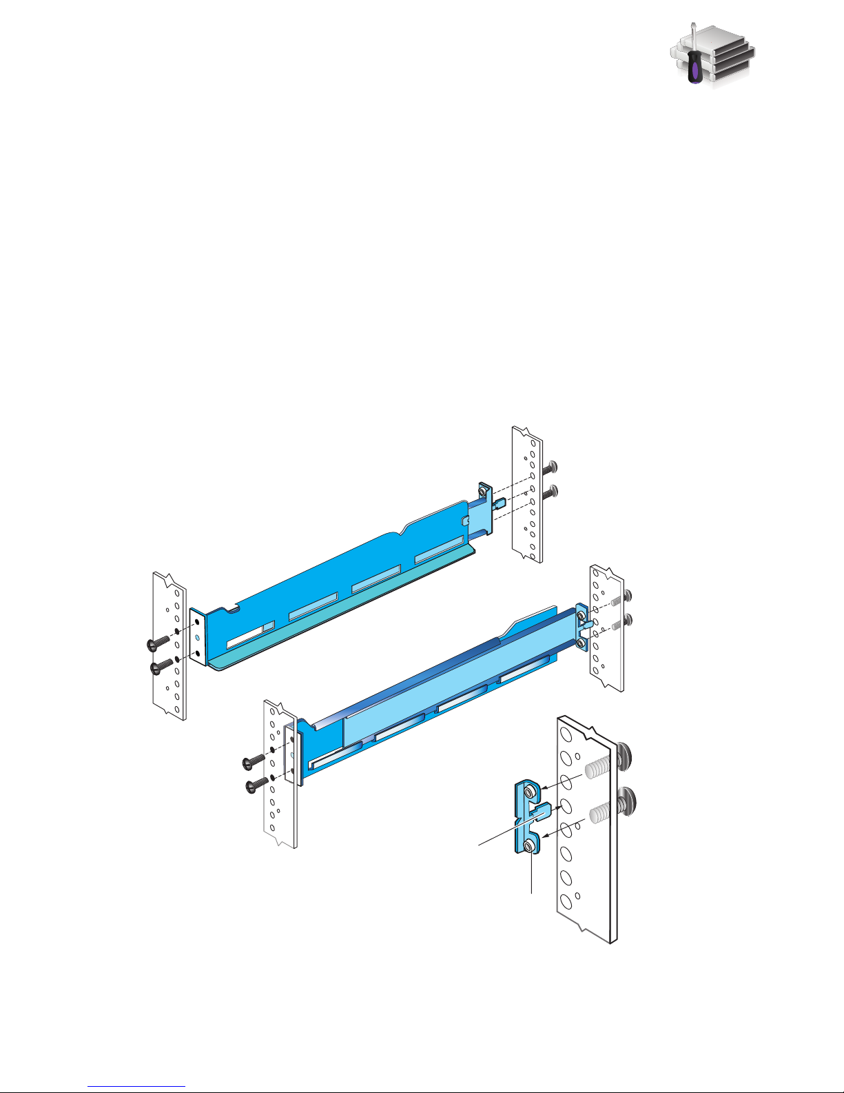
Installing rails
Installing the SPS rails
The standby power supply (SPS) is a 1U component and uses a 1U adjustable rail kit. If possible,
start the installation from the bottommost allowed space in your cabinet.
1. Insert the adjustable rail slide and seat the rail extensions into the rear channel of your
cabinet.
2. Extend the rail and align the front of the rails as shown. Ensure that they are level front to back
and with the companion rail, left to right.
3. Insert two retention screws in the front and two retention screws in the back of each rail as
shown in Figure 1.
Figure 1 Installing the SPS rails
Assemble components in your cabinet
11
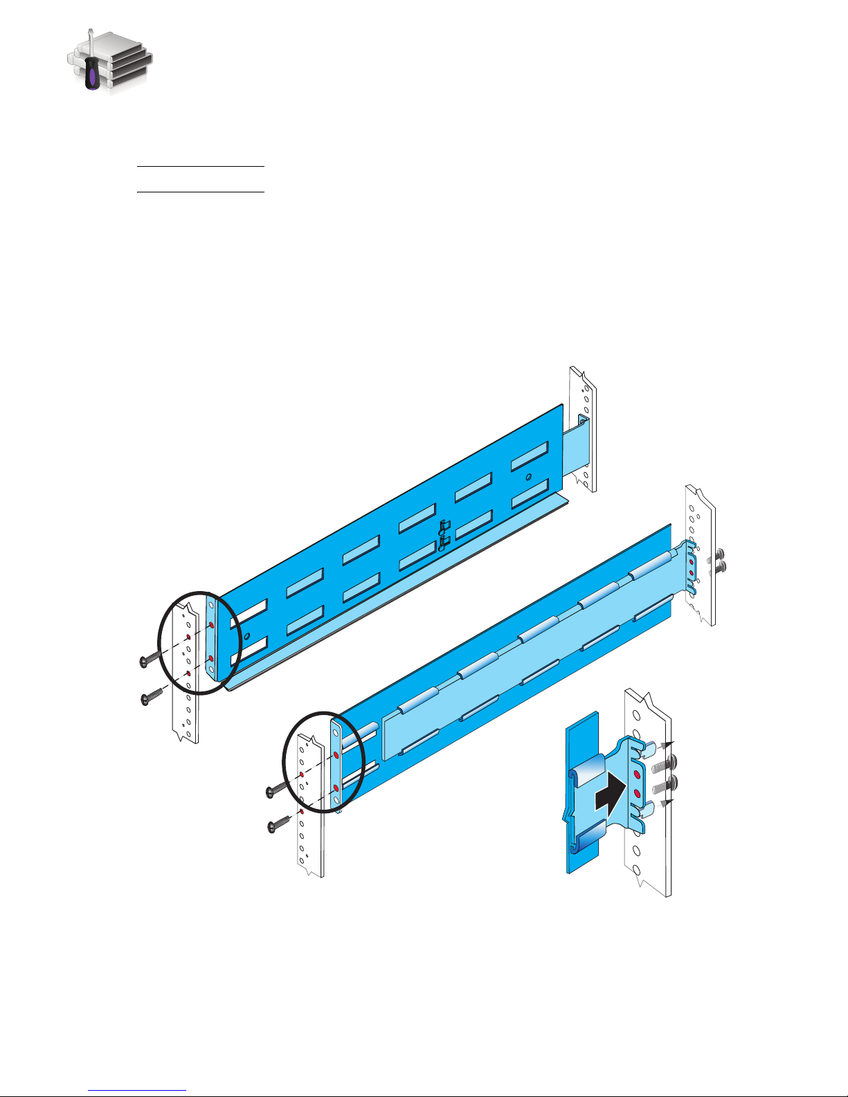
Installing the DPE rails
The DPE rails should be installed immediately above the SPS rails.
Note: All rails must be aligned level front to back and with the companion rail, left to right.
1. Insert the adjustable 3U rail slide and seat both alignment pins into the rear channel of your
cabinet.
2. Extend the rail and align the front of the rails as shown in Figure 2.
3. Insert two retention screws in the middle two holes in the front.
4. Insert two retention screws in the back of each rail.
Front
L
Figure 2 Installing the DPE rails
Rear
Detail
2 Alignment
pins
R
2 Screws
VNX-000215
12
EMC VNX5300 Block Installation Guide
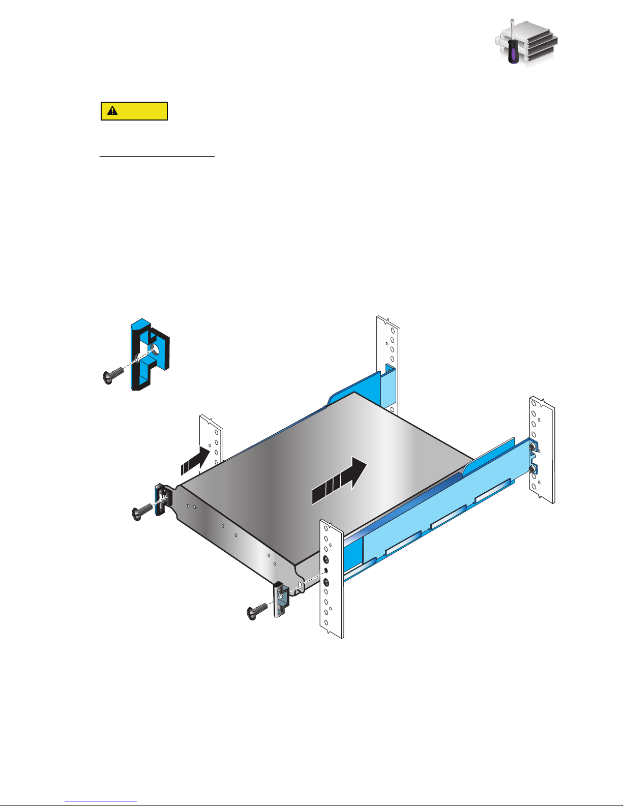
Installing the components
Standby power supply enclosure
Front
SPS 1 unit bracket
The indentation is
toward the inside of
the rack.
VNX-000766
Some of the components are heavy and may require two people. If needed, use an appropriate
lifting device (mechanical lift).
Installing the standby power supply
1. Slide the SPS enclosure into the cabinet rails at the bottom of the rack as shown in Figure 3.
Ensure that the enclosure is fully in the cabinet. The rail stops in the back will seat into the
back of the enclosure at the correct depth, and the front of the enclosure will be flush with the
cabinet face.
2. When the SPS is in place, insert the screws and bezel brackets to hold the enclosure in place
in the cabinet. Do not tighten the screws completely until all of the components are in place .
Figure 3 Installing the standby power supply
Installing the components
13
1 X4
2
3
4
5
6Gb
SAS
8Gb
bre
0 X4
6Gb SAS
A
2
3
4
5
6Gb
SAS
8Gb
bre
0 X4
6Gb SAS
B
1 X4
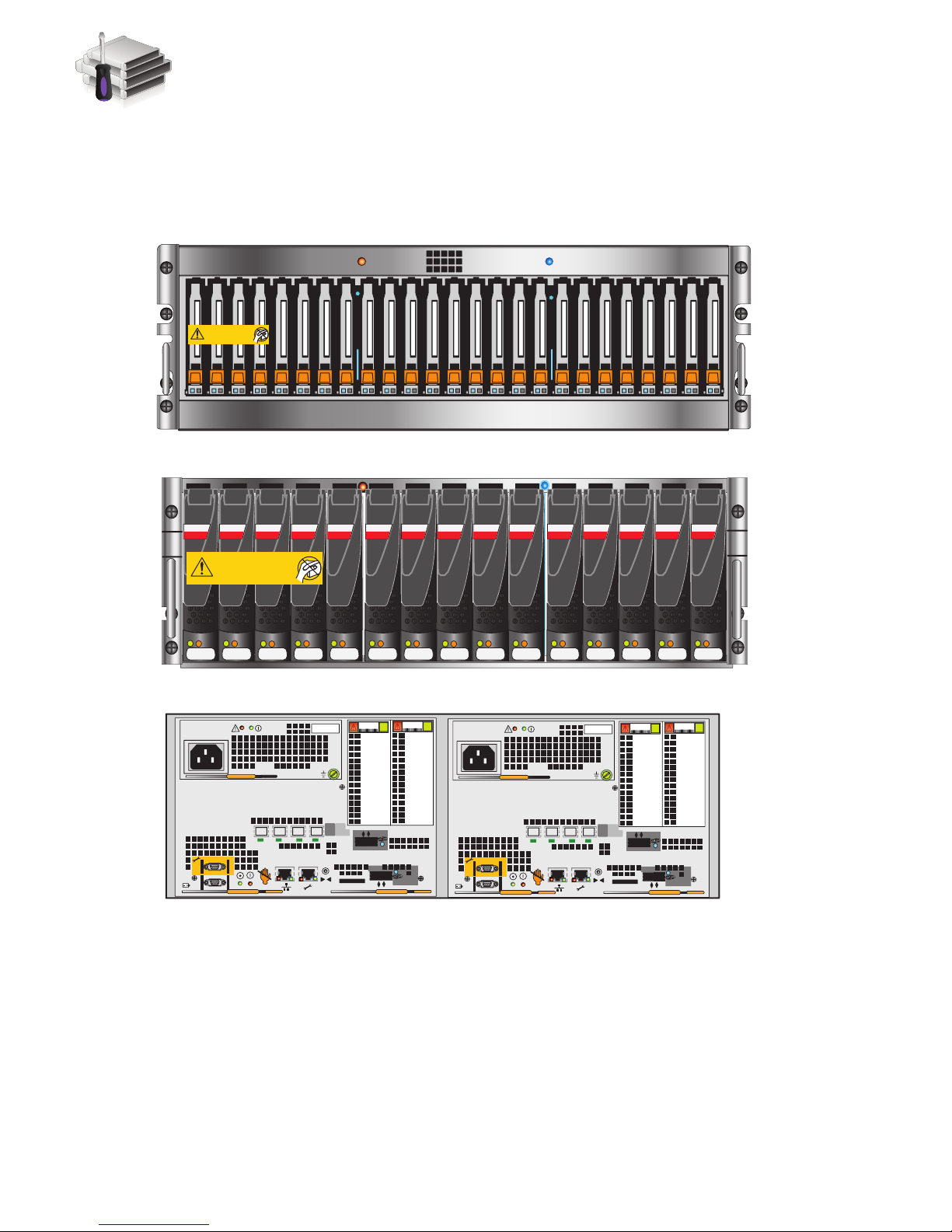
3U, Disk processor enclosure Rear
VNX-000189
14
0
SAS SAS SAS SAS SAS SAS SAS SAS SAS SAS SAS SAS SAS SAS SAS
24
0
12345678910 11 12 13 14 15 16 17 18 19 20 21 22 23 24
0
3U, 25 2.5” drive Disk processor enclosure front
3U, 15 3.5” drive Disk processor enclosure front
Will Make the Array Unusable
Caution: Array Software on drives 0-3. Removing or relocating them
Will Make the Array Unusable
Caution: Array Software on drives 0-3. Removing or relocating them
Installing the disk processor enclosure
There are two types of disk processor enclosures (DPEs). Your disk processor enclosure can be
either a 3U, 25 2.5” drive DPE or a 3U, 15 3.5” drive DPE as shown in Figure 4.
Figure 4 Types of DPE(s)
14
EMC VNX5300 Block Installation Guide
 Loading...