

Page 1

EMC®VNX™Procedure Generator
T o p i c
S e l e c t i o n s
Generated:
2013/7/24 11:21:15
SolVe Generator Updated:
Replacing the Data Mover Enclosure (DME)
VNX5300 Procedures
VNX5300 Activity Type: Hardware Replacements
VNX5300 File/Unified HW Replacements: Data Mover Enclosure (DME)
五月 30, 2013
IMPORTANT: To be sure you have the latest SolVe generator application and content, always choose Yes
when asked if you want to update the application or repository.
REPORT PROBLEMS
If you find any errors in this procedure or have comments regarding this application, send email to
SolVeFeedback@emc.com
Copyright©2010 –2013 EMC Corporation. All rights reserved.
Publication Date: July, 2013
EMC believes the information in this publication is accurate as of its publication date. The information is subject to
change without notice.
THE INFORMATION IN THIS PUBLICATION IS PROVIDED “AS IS.” EMC CORPORATION MAKES NO
REPRESENTATIONS OR WARRANTIES OF ANY KIND WITH RESPECT TO THE INFORMATION IN THIS
PUBLICATION, AND SPECIFICALLY DISCLAIMS IMPLIED WARRANTIES OF MERCHANTABILITY OR FITNESS
FOR A PARTICULAR PURPOSE.
Use, copying, and distribution of any EMC software described in this publication requires an applicable software
license.
For the most up-to-date regulatory document for your product line, go to the Technical Documentation and Advisories
section on EMC Powerlink.
For the most up-to-date listing of EMC trademarks, see the list of EMC Corporation Trademarks on EMC.com.
All other trademarks used herein are the property of their respective owners.
EMC CONFIDENTIAL version: 4.5
1 of 51
Page 2

EMC®VNX™Procedure Generator
Contents
Handling Field Replaceable Units (FRUs).........................................................................4
FRUs and Power Issues..........................................................................................................................4
Avoiding Electrostatic Discharge (ESD) damage......................................................................................4
Emergency procedures (without an ESD kit).......................................................................................5
Removing, installing, or storing FRUs .................................................................................................5
Replacing a Blade Enclosure (DME)................................................................................. 6
Task Summary ........................................................................................................................................6
Task 1: Diagnose and identify Faulted FRU.......................................................................................6
Receive an email notification.......................................................................................................7
Log in to EMC Unisphere ............................................................................................................7
Check the Fault LED...................................................................................................................7
Check the Blade enclosure fault LEDs.........................................................................................8
Task 2: Disabling ConnectHome and Email Notifications...................................................................9
Task 3: Saving Resume PROM Configuration Information.................................................................9
Task 4: Halting the Secondary Control Station.................................................................................11
Task 5: Prepare for Replacement....................................................................................................12
Single-Blade system.........................................................................................................................13
Multi-Blade system ...........................................................................................................................13
Task 6: Remove Faulted DME.........................................................................................................16
Task 7: Install the Replacement DME..............................................................................................18
Transfer Components to the Replacement DME........................................................................19
Removing a Power/Cooling module...........................................................................................19
Remove the CPU Filler Assembly..............................................................................................20
Removing a CPU module..........................................................................................................21
Installing a CPU module............................................................................................................21
Reinstall the CPU Filler Assembly .............................................................................................22
Installing a Power/Cooling Module.............................................................................................22
Transfer Management Modules and I/O Modules..............................................................................23
Removing a Management Module.............................................................................................23
Installing a Management module...............................................................................................24
Removing an I/O module...........................................................................................................24
Installing an I/O module.............................................................................................................25
Transfer the Serial Number Tag ................................................................................................26
EMC CONFIDENTIAL version: 4.5
2 of 51
Page 3

EMC®VNX™Procedure Generator
Reconnect Blade Enclosure Cables ..........................................................................................27
Task 8: Configure the replacement BE Resume PROM...................................................................27
Set up the Work Environment on the Blade...............................................................................27
Configure the BE Resume PROM.....................................................................................................28
Task 9: Collect System Information .................................................................................................31
Set up the Work Environment on the Control Station.................................................................31
Collect System Information and Save SP Logs..........................................................................32
Task 10:Configure the HBA/Initiator Records....................................................................................35
Set Up the Replacement BE......................................................................................................35
Remove the old initiator records................................................................................................36
Collect the New WWNs.............................................................................................................37
Zone the FC switch(s)...............................................................................................................39
Recreate the initiator records ....................................................................................................39
Verify the New Connections ......................................................................................................42
Configure the Blades.................................................................................................................43
Task 11:Test the Functionality of the System....................................................................................44
Task 12:Installing the Blade Enclosure Front Bezel ..........................................................................46
Task 13:Check System Status..........................................................................................................47
Task 14:FRU failures .......................................................................................................................48
Task 15:Enabling ConnectHome and Email Notifications..................................................................48
Finish ....................................................................................................................................................49
Parts Return..............................................................................................................................51
EMC CONFIDENTIAL version: 4.5
3 of 51
Page 4
EMC®VNX™Procedure Generator
Handling Field Replaceable Units (FRUs)
This section describes precautions you must take and generalprocedures you must follow when removing,
installing, or storing field-replaceable units (FRUs). The procedures in this section apply to FRU handling
during hardware upgrades as well as during general replacement.
FRUs and Power Issues
FRUs are designed to be powered up at alltimes. This means you can replace FRUs and accomplish most
hardware upgrades while the cabinet is powered up. To maintain proper airflow for cooling and to ensure
EMI compliance, make sure all front bezels, filler panels, and filler modules are reinstalled after the FRU
replacement or hardware upgrade is completed. Do not remove a faulty FRU from the system until you have
a replacement available.
CAUTION: When you want to power down a storage processor enclosure (SPE), turn off the power
switch on the enclosure’s standby power supply (SPS). Never turn off the SPE’s power supply
switches. Turning off the SPE power supply switches instead of the SPS power switch shuts down
the storage processors before they have enough time to save the write-cache data to the vault
drives. This causes data loss.
If write-cache data is not saved, the storage processor log displays an error message similar to the
following:
Enclosure 0 Disk 5 0x90a (Can’t Assign - Cache Dirty) 0 0xafb40 0x14362c.
If you see this error message, contact Customer Service immediately.
Avoiding Electrostatic Discharge (ESD) damage
When replacing or installing FRUs, you can inadvertently damage the sensitive electronic circuits in the
equipment by simply touching them. Electrostatic charge that has accumulated on your body discharges
through the circuits. If the air in the work area is very dry, running a humidifier in the work area helps
decrease the risk of ESD damage. You must use the following procedures to prevent damage to the
equipment, so read the following instructions carefully.
Provide enough room to work on the equipment. Clear the work site of any unnecessary materials or
materials that naturally build up electrostatic charge, such as foam packaging, foam cups, cellophane
wrappers, and similar items.
Do not remove replacement or upgrade FRUs from their antistatic packaging until you are ready to
install them.
Gather the ESD kit and all other materials you will need before you service a component. Once
servicing begins, you should avoid moving away from the work site; otherwise, you may build up an
electrostatic charge.
Use the ESD kit when handling any FRU.
If an emergency arises and the ESD kit is not available, follow theprocedures in the section
procedures (without an ESD kit)
.
Emergency
Use the ESD wristband that is supplied with your system.
EMC CONFIDENTIAL version: 4.5
4 of 51
Page 5

EMC®VNX™Procedure Generator
To use it, attach the clip of the ESD wristband (strap) to any bare (unpainted) metal on the cabinet
enclosure; then secure the wristband around your wrist with the metal button against your skin.
Emergency procedures (without an ESD kit)
In an emergency, when an ESD kit is not available, use the following procedures to reduce the possibility of
an electrostatic discharge by ensuring that your body and the subassembly are at the same electrostatic
potential.
IMPORTANT: These procedures are not a substitute for the use of an ESD kit. You should follow them
only in the event of an emergency.
Before touching any FRU, touch a bare (unpainted) metal surface of the enclosure.
Before removing any FRU from its antistatic bag, place one hand firmly on a bare metal surface of the
enclosure, and at the same time, pick up the FRU while it is still sealed in the antistatic bag. Once you
have done this, do not move around the room or contact other furnishings, personnel, or surfaces until
you have installed the FRU.
When you remove a FRU from the antistatic bag, avoid touching any electronic components and
circuits on it.
If you must move around the room or touch other surfaces before installing a FRU, first place the FRU
back in the antistatic bag. When you are ready again to install the FRU, repeat these procedures.
Removing, installing, or storing FRUs
Use the following precautions when you remove, handle, or store FRUs:
Do not remove a FRU from the cabinet until you have the replacement available.
Handle a FRU only when wearing a properly attached ESD wristband:
Attach the clip of the ESD wristband to the ESD bracket or to a bare metal portion of the FRU’s
enclosure.
Secure the wristband around your wrist with the metal button against your skin.
Handle a FRU gently. A sudden jar, drop, or vibration can permanently damage some FRUs.
The weight of some FRUs is not evenly distributed. To prevent personal injury or equipment damage
when removing, installing, or handling theses FRUs, use both hands and provide extra support at the
heavy end of the FRU.
Never use excessive force to remove or install a FRU.
Store a FRU in the antistatic bag and the specially designedshipping container in which you received it.
Use this special shipping container when you need to return the FRU.
If you need to store a FRU for a short time, make sure the temperature of the location where you store
FRU is within the limits specified by the FRU’s Technical Specifications.
Disk modules are sensitive to the extreme temperatures sometimes encountered during shipping. We
recommend that you leave a new disk modules in its shipping container and allow it to acclimate to the
installation site’s ambient temperature for at least four hours before operating the new module in the
system.
When removing a disk module, pull the module part way out of the slot, then wait 30 seconds for the
drive to spin down before removing it.
EMC CONFIDENTIAL version: 4.5
5 of 51
Page 6

EMC®VNX™Procedure Generator
When installing multiple disks in a powered-up system, wait at least 6 seconds before sliding the
second and each subsequent disk into the system.
Place a disk module on a soft, antistatic surface, such as an industry-standard antistatic foam pad or
the container used to ship the module. Never place a disk module directly on a hard surface.
WARNING: The weight of some FRU assemblies is not evenly distributed. To prevent personal
injury or equipment damage when handling FRU assemblies, make sure you provide extra support
at the heavy end of a FRU assembly.
Replacing a Blade Enclosure (DME)
This procedure explains how to replace a Blade enclosure (aka, Data Mover, DME). The tasks apply to
DMEs in VNX5300 through 7500 models with VNX for File systems.
CAUTION: Electrostatic discharge (ESD) can damage equipment and impair electrical circuitry.
Always follow ESD prevention procedures when removing and replacing Customer-Replaceable
Units (CRUs) and Field-Replaceable Units (FRUs).
Task Summary
This procedure assumes that you are reinstalling (transferring) the power/cooling modules, management
modules, Blades, and I/O modules from the faulted Blade enclosure to the replacement Blade enclosure.
So that you can understand what is involved, the table of Contents lists the high-level tasks required for this
procedure. Take a moment to become familiar with these tasks. If you have any questions, contact
Customer Support before you begin the procedure.
CAUTION: This procedure takes approximately three hours to complete. During this time, the NAS
service is stopped and service is disrupted. Any process initiated by the Control Station (CS) or
any commands run from the
time.
Note: This procedure shows command output collected from a two X-Blade (Blade) system, unless
otherwise specified. Be aware that the actual command output will differ depending on the number of
Blades in the system. Additionally, output values displayed in the document are for the specific system used
to create this procedure.
WARNING: The weight of some FRU assemblies is not evenly distributed. To prevent personal
injury or equipment damage when handling an assembly, make sure you provide extra support at
the heavy end of the assembly.
Task 1: Diagnose and identify Faulted FRU
/nas directory is inhibited. You cannot manage the system during this
There are multiple ways to diagnose and identify a faulted FRU component. Follow the instructions below to
diagnose a problem with an FRU:
EMC CONFIDENTIAL version: 4.5
6 of 51
Page 7

EMC®VNX™Procedure Generator
Receive an email notification
If the system detects a problem with an internal component, the system may send an email notification
outlining the problem detected and recommending steps to correct the problem. If you receive an email
notification, follow the recommended steps described in the email.
Log in to EMC Unisphere
You can log in to Unisphere to diagnose a problem with a hardware component. Do the following:
1. [ ] Open Unisphere in an Internet browser using the following URL:
https://<control_station>
where <control_station> is the hostname or IP address of the primary Control Station (CS).
a. At the login prompt, log in as
b. Set the scope to
After logging in, the Unisphere
component status and the alerts for managed systems on the
new alert in the
Note: Alerts will not automatically clear. Delete old alerts by right-clicking on the alert and selecting
Delete.
2. [ ] Use the drop-down list at the top left of the Dashboard to select the system that contains faulted
hardware.
3. [ ] Select
components.
4. [ ] Check the system inventory for faulted hardware components.
5. [ ] Record the full component name for any faulted hardware found on the
The component name contains important information about hardware location.
For example, a Blade enclosure is listed in Unisphere as
number.
System > Hardware > Hardware for File to view information about the hardware
Global.
Alerts quadrant and select Details to view the associated error message.
sysadmin. The default password is sysadmin.
Dashboard page appears. Unisphere displays the system’s hardware
Dashboard. You can right-click on any
Hardware for File page.
DME 0, where 0 is the Blade enclosure (DME)
Check the Fault LED
To check the fault LEDs found on the front of the system, you must remove the front bezel to expose them
and then check for faulted components.
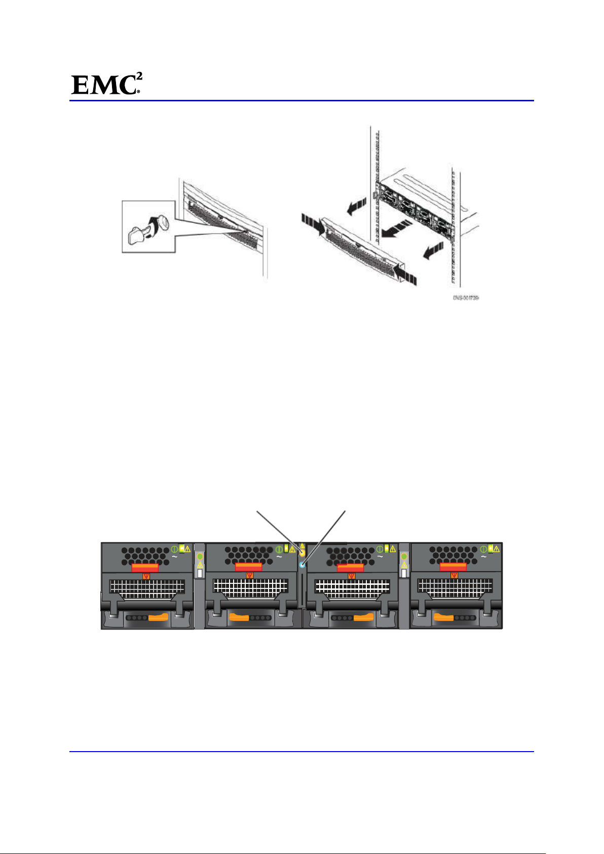
6. [ ] Turn the key at the front of the bezel enclosure counterclockwise.
7. [ ] Press the latches on the front of the bezel, and pulling the bezel toward you (Figure 1).
EMC CONFIDENTIAL version: 4.5
7 of 51
Page 8
EMC®VNX™Procedure Generator
Blade enclosure
Blade enclosure
CNS-001667
Figure 1 Unlocking and removing the Blade enclosure (front bezel)
Check the Blade enclosure fault LEDs
If you are near the front of the system, you can easily check the Blade enclosure fault LED.
8. [ ] Locate the Blade enclosure.
For a multi-Blade enclosure system, if you recorded the information listed in Unisphere during the
previous task, find the faulted Blade enclosure using the management module seven-segment LED on
the rear of each Blade enclosure and the recorded fault information.
9. [ ] Check the Blade enclosure fault LED. Figure 2 shows the LEDs visible for the Blade enclosure
from the front of the Blade enclosure.
fault LED
AC AC AC AC
Figure 2 Blade enclosure fault LED (frontview)
power LED
10. [ ] If a Blade enclosure LED or Unisphere show a faulted Blade enclosure, continue with this
replacement procedure.
11. [ ] If each Blade enclosure LED or Unisphere does not show a faulted Blade enclosure, it does not
need to be replaced.
EMC CONFIDENTIAL version: 4.5
8 of 51
Page 9
EMC®VNX™Procedure Generator
Recheck the Unisphere to see if another component has faulted. If the Unisphere shows another
component has faulted, it might need to be replaced instead of a Blade enclosure.
Task 2: Disabling ConnectHome and Email Notifications
For VNX OE for File 7.0 or later, use a HyperTerminal or PuTTY session to disable ConnectHome:
12. [ ] From the root directory, disable ConnectHome:
/nas/sbin/nas_connecthome -service stop
13. [ ] Disable the email notification service:
/nas/bin/nas_emailuser -modify -enabled no
14. [ ] Verify that the email notification service has stopped (is not enabled):
/nas/bin/nas_emailuser –info
15. [ ] ConnectHome and email notifications are now disabled on your VNX OEFile system. Skip over the
next Block task to begin the service activity.
Task 3: Saving Resume PROM Configuration Information
Save the Resume PROM configuration information for the faulted Blade enclosure (BE). You use this
information later to reconfigure the replacement enclosure.
1. [ ] Open the
in
/nas/log directory.
where
<Blade_enclosure_number> is the ID (0, 1, 2, or 3) of the faulted BE.
enclosure_resume.enclosure_<Blade_enclosure_number>.xml file located
Table 1 lists the BEs associated with each enclosure.
Table 1 Blade Enclosure ID and Blade mapping
Blade Enclosure ID Blades
0 2 and 3
1 4 and 5
2 6 and 7
3 8 and 9
2. [ ] Within this file, find and record, in Table 2, thevalues for the Resume PROM information contained
in the
RESUME_INFORMATION_MIDPLANE section.
Example XML file:
EMC_BARE_ASSEMBLY_PART_NUMBER="100-562-440 "
EMC_BARE_ASSEMBLY_REVISION="A03"
EMC_BARE_ASSEMBLY_SERIAL_NUMBER="FCNTR082900499 "
EMC_PART_NUMBER=" "
EMC_ARTWORK_REVISION=" "
EMC_ASSEMBLY_REVISION=" "
EMC_SERIAL_NUMBER=" "
EMC_PRODUCT_PART_NUMBER="900-567-002 "
EMC CONFIDENTIAL version: 4.5
9 of 51
Page 10

EMC®VNX™Procedure Generator
EMC_PRODUCT_SERIAL_NUMBER="FCNCH095103338 "
VENDOR_NAME="Blank "
LOCATION_OF_MANUFACTURE="Blank "
YEAR_OF_MANUFACTURE=" "
MONTH_OF_MANUFACTURE=" "
DAY_OF_MONTH_OF_MANUFACTURE=" "
ASSEMBLY_NAME=" "
/>
Table 2 Resume PROM information
RESUME_INFORMATION_MIDPLANE
field name
EMC_PART_NUMBER EMC SYSTEM HARDWARE TLA PN
EMC_ASSEMBLY_REVISION EMC SYSTEM HARDWARE TLA Rev
EMC_SERIAL_NUMBER EMC SYSTEM HARDWARE TLA SN
EMC_PRODUCT_PART_NUMBER PRODUCT PN
EMC_PRODUCT_SERIAL_NUMBER PRODUCT SN
ASSEMBLY_NAME ASSEMBLY_NAME
Note 1: All of this information except the ASSEMBLY_NAME should also be on the serial number tag located on the rear of the BE
enclosure.
Note 2: The field names listed in Corresponding Resume PROM Field correspond to the value prompts found in Configure the
BE Resume PROM.
Value Corresponding Resume PROM Field
Note: The CE should contact support and get the Resume PROM configuration data from CSI if not
available locally.
3. [ ] The Resume PROM values for the faulted BE have been collected.
EMC CONFIDENTIAL version: 4.5
10 of 51
Page 11

EMC®VNX™Procedure Generator
Task 4: Halting the Secondary Control Station
If your system is a dual Control Station system, the secondary CS (CS 1) must be stopped before NAS
services on the primary CS are stopped; otherwise, the secondary CS will takeover. If your system does not
have dual Control Stations (CS 0 and CS 1), skip this section.
Note: If the secondary CS is currently acting as the primary CS, you may need to failback and then
continue to power down the secondary CS.
This task halts the secondary control station:
1. [ ] At the rear of the cabinet, connect the null modem cable from a serial port on your management
console to the secondary Control Station, CS 1.
2. [ ] Open the HyperTerminal or PuTTY session using the following settings:
Bits per second: 19200
Data bits: 8
Parity: None
Stop bits: 1
Flow control: None
Emulation: Auto Detect
Telnet terminal ID: ANSI
Bits per second:
_
Data bits: _8 _
Parity: _None _
Stop bits: _1 _
Flow control: _None _
Emulation: _Auto Detect _
Telnet terminal ID: _ANSI _
EMC CONFIDENTIAL version: 4.5
11 of 51
Page 12
EMC®VNX™Procedure Generator
Control Station (front)
Powerb
utton
3. [ ] Login in to CS 1 as
nasadmin.
4. [ ] Change to the root user by entering the following command:
$ su root
5. [ ] Halt the secondary CS by entering the following command:
# /sbin/halt
Note: This may take a few minutes to complete. Ensure it is finished before you continue.
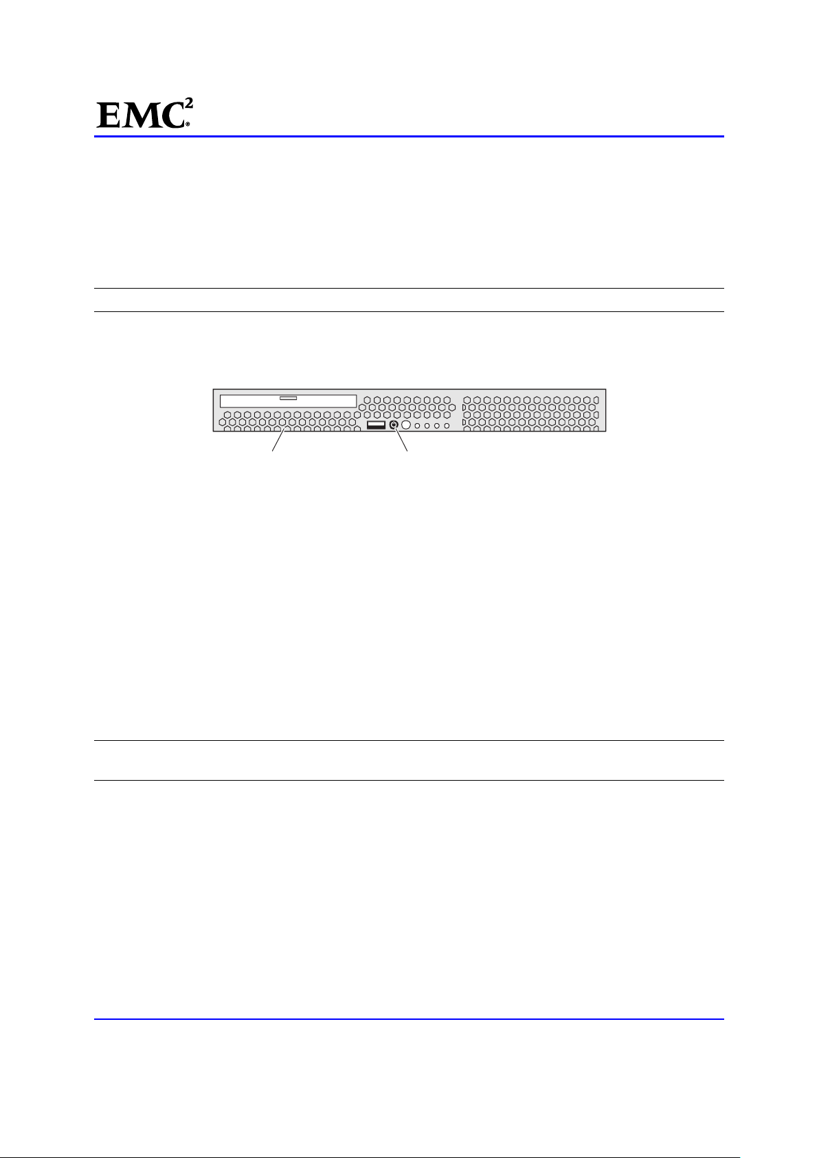
6. [ ] Press and hold the power button to power down CS 1. The Control Station power button is shown
in Figure 3. Remove the bezel to access this button.
CNS-000876
Figure 3 Control station power button
7. [ ] Wait 30 seconds for the internal disk drive to stop spinning and safely park its heads before
continuing.
8. [ ] Disconnect the CS 1 power cable from the power distribution panel (PDP).
9. [ ] Close the HyperTerminal or PuTTY session with CS 1.
10. [ ] Reconnect your management console to the serial port on CS 0 and reopen the HyperTerminal or
PuTTY session on CS 0 using the settings found in Step 2.
11. [ ] The secondary CS is halted and powered off.
Task 5: Prepare for Replacement
To prepare a faulted BE for removal from the system, its internal components must be halted and removed.
This section provides steps for preparing the system for the replacement of a BE.
Note: This document uses the term Blade to refer to a component that is defined as a logical construct of a
CPU module with its associated I/O modules.
Follow the procedure that best matches the system’s Blade configuration to prepare the system for the BE
replacement:
Multi-Blade system
Single-Blade system
Multi-Blade system
EMC CONFIDENTIAL version: 4.5
12 of 51
Page 13

EMC®VNX™Procedure Generator
Single-Blade system
For a single-Blade system, prepare the Blade for removal by doing the following:
1. [ ] Unmount the file systems and prepare the Blade to be halted by typing:
# /nas/bin/server_cpu server_2 -q now
2. [ ] Stop the NAS service on the primary CS by entering:
CAUTION: Stopping the NAS service disrupts service on the system. Any process initiated
by the Control Station or any commands run from the /nas directory are inhibited. Do not to
attempt to run this command while working in the
# /sbin/service nas stop
This command takes up to five minutes to complete. If this command fails, reboot the CS and try
again.
3. [ ] Halt the Blade by typing:
CAUTION: When you shut down the Blade, you will lose access to the public networks and file
systems. Verify that the customer is prepared for this action.
# /nasmcd/sbin/t2reset pwroff -s 2
/nas directory.
4. [ ] Wait three minutes for the previous command to complete and then verify that the Blade has
powered off:
Note: The getreason command can be augmented to provide continuous monitoring of the system
reason codes by adding the watch command. Use Ctrl/C to stop end the monitoring. For example # watch
/nasmcd/sbin/getreason
Example Output:
# /nasmcd/sbin/getreason
6 - slot_0 primary control station
- slot_2 powered off
5. [ ] Remove the enclosure from the NAS database:
# /nasmcd/sbin/setup_enclosure -removeEnclosure 0
6. [ ] The BE is removed from the NAS database and the NAS service is stopped.
Disconnect the faulted Blade enclosure's two power cables from the rack.
Multi-Blade system
For a multi-Blade system, prepare the Blade enclosure for removal by doing the following:
1. [ ] Determine the failover status of the Blades by entering:
# /nas/bin/nas_server -info –all
Sample Output:
id = 1
name = server_2.faulted.server_3
acl = 0
type = standby
EMC CONFIDENTIAL version: 4.5
13 of 51
Page 14
EMC®VNX™Procedure Generator
slot = 2
member_of =
standbyfor= server_2
status :
defined = out_of_service
actual = online, ready
id = 2
name = server_2
acl = 0
type = nas
slot = 3
member_of =
standby = server_2.faulted.server_3, policy=manual
status :
defined = enabled
actual = online, ready
Refer to Table 3 for command reference information.
Table 3 nas_server output definitions
Value Definition
id ID of the Blade.
name Name given to the Blade.
acl Access control level value assigned to the Blade or VDM.
type Type assigned to the Blade. (nas=primary; standby=standby)
slot Physical slot in the system where the Blade resides.
member_of Group to which the Blade is a member.
standby If the Blade has a local standby associated with it.
standbyfor If the Blade has a local standby, lists associated primary.
status Whether the Blade is enabled or disabled, and whether it is active.
2. [ ] Go to Step 4 if the system is configured with only one Blade enclosure, otherwise continue.
3. [ ] For a multi-Blade enclosure system, prepare each Blade in the faulted BE for removal. Repeat this
step for each Blade in the faulted enclosure before continuing to the next step.
a. If the Blade is a primary Blade and has no standby Blade configured, no action is required.
b. If the Blade is a primary Blade that has a standby Blade configured in another BE, failover to that
standby Blade:
# /nas/bin/server_standby <server_name> -activate mover
Where <server_name> is the name of the server. Use the nas_server –list command to get
the server name.
c. If the Blade is configured as a standby Blade and is currently standing in for an available primary Blade
contained in another BE, enter the following command:
# /nas/bin/server_standby <server_name> -restore mover
where <server_name> is the name of the server. Use the nas_server –list command to get
the server name.
Example:
EMC CONFIDENTIAL version: 4.5
14 of 51
Page 15

EMC®VNX™Procedure Generator
In a four Blade system with BE 1 faulted, Blade 2 has failed over to Blade 4, its standby. The
command to restore Blade 2 as the primary Blade is:
# /nas/bin/server_standby server_2 -restore mover
d. If the Blade is configured as a standby Blade and is not currently standing in for a primary Blade
contained in another BE, remove the Blade as a standby. Enter the following command:
Note: A Blade can be configured as a standby for multiple primary Blades. Repeat this step for each
primary Blade for which the Blade is a standby. Afterwards, go to step 4.
# /nas/bin/server_standby <server_name> -delete mover
where <server_name> is the name of the primary Blade. Use the nas_server -list command to get
the Blade name.
4. [ ] Stop the NAS service by entering:
CAUTION: Stopping the NAS service disrupts service on the system. Any process initiated by
the Control Station or any commands run from the /nas directory is inhibited. Do not to
attempt to run this command while working in the
# /sbin/service nas stop
This command will take up to five minutes to complete. Make sure it is finished before you continue. If
this command fails, reboot the CS and try again.
/nas directory.
5. [ ] Power off each Blade in the faulted BE:
CAUTION: When you shut down a Blade in a single BE system, you will lose access to the
public networks and file systems. Verify that the customer is prepared for this action.
# /nasmcd/sbin/t2reset pwroff -s <slot_number>
Where <slot_number> is the slot ID number of the Blade inside the BE.
6. [ ] Wait three minutes for the previous commands to complete and then verify that the Blades have
powered off:
Note: The getreason command can be augmented to provide continuous monitoring of the system
reason codes by adding the watch command. Use Ctrl/C to stop the monitoring. For example, watch
/nasmcd/sbin/getreason
Example:
6 - slot_0 primary control station
- slot_2 powered off
- slot_3 powered off
.
7. [ ] Remove the enclosure from the NAS database:
# /nasmcd/sbin/setup_enclosure -removeEnclosure <Blade_enclosure_number>
where <Blade_enclosure_number> is the BE number (shown on the LED display on the
management modules) of the faulted BE.
8. [ ] The BE is removed from the NAS database and the NAS service is stopped. Disconnect the faulted
Blade enclosure's two power cables from the rack.
EMC CONFIDENTIAL version: 4.5
15 of 51
Page 16
EMC®VNX™Procedure Generator
CL4138a
Task 6: Remove Faulted DME
You should remove the faulted chassis with all its components installed. After you install the replacement
chassis in the cabinet, you must transfer the components from the faulted chassis to the replacement
chassis. This process helps to ensure the correct placement of the components.
CAUTION: The enclosure is heavy and should be installed into a rack by two people (or a
data-center lift tool). To avoid personal injury and/or damage to the equipment, do not attempt to lift
and install the enclosure without a mechanical lift or help from another person.
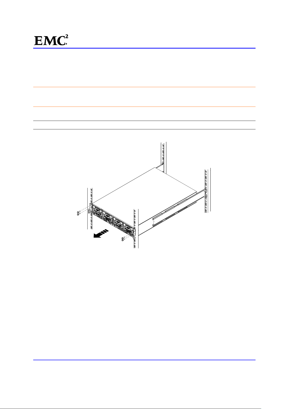
1. [ ] Remove four M5 12.7 mm screws (two per side) to release the chassis from the cabinet (Figure 4).
Note: The screws also secure the latch brackets mounted on the front of the chassis.
Figure 4 Removing Securing Screws
2. [ ] From the front of the cabinet and, with help from another person, lift the chassis and slide it out of
the cabinet (Figure 5).
3. [ ] Place the enclosure on a work surface.
EMC CONFIDENTIAL version: 4.5
16 of 51
Page 17

EMC®VNX™Procedure Generator
CL4137a
Figure 5 Removing Chassis from Cabinet
4. [ ] Place the enclosure on a work surface.
EMC CONFIDENTIAL version: 4.5
17 of 51
Page 18

EMC®VNX™Procedure Generator
CL4137b
Task 7: Install the Replacement DME
This task installs the DME chassis in the cabinet:
1. [ ] From the front of the cabinet, lift the chassis and slide it onto the rails (Figure 6).
When the chassis slides to the back of the cabinet, the two notches in the rear of the chassis insert into
the rear tabs on each rail. The tabs secure and support the rear of the chassis.
If the chassis does not slide all the way into the cabinet, you may need to loosen the screws that hold
the rear of the rails in place, then adjust the rails to allow the tabs to fit into the notches.
Figure 6 Sliding the DME into the Cabinet
EMC CONFIDENTIAL version: 4.5
18 of 51
Page 19

EMC®VNX™Procedure Generator
CL4138b
2. [ ] Secure the front of the chassis to the vertical channels of the cabinet using four M5 12.7 mm
screws (two per side) (Figure 7).
Figure 7 Securing the DME to the Cabinet
Transfer Components to the Replacement DME
You must transfer the power/cooling modules, CPU modules, management modules, and I/O modules from
the faulted chassis to the corresponding locations in the replacement chassis. Use the procedures in the
sections that follow to transfer these components.
You must transfer the power/cooling modules and the CPU modules from the faulted chassis to the same
locations in the replacement chassis one component at a time. Transfer components from the A side first
(from the rear of the system, this is the right side), then transfer components from the B side (from the rear
of the system, this is the left side).
For each Blade, starting with the components on the A side (from the front of the system, this is the left side),
complete the following steps, as described in the sections that follow, to transfer the power/cooling modules
and the CPU modules:
Removing a Power/Cooling module
3. [ ] Locate and press the orange tab on the power/cooling module (Figure 8)
EMC CONFIDENTIAL version: 4.5
19 of 51
Page 20

EMC®VNX™Procedure Generator
You hear an audible click when the tab is pressed and the latch is released.
4. [ ] Lower the latch to release the power/cooling module from the CPU module.
Note: The orange tabs on the power/cooling module are labeled with a 1.
5. [ ] Pull the power/cooling module out of the chassis (Figure 8) and place it on an antistatic surface.
CL3972
Figure 8 Removing a Power/Cooling module
Remove the CPU Filler Assembly
If present, remove the CPU filler assembly. Otherwise, skip to the next task. To remove the CPU filler
assembly:
6. [ ] Locate and press the orange latches away from each other to fully release the CPU filler assembly
(Figure 9).
ACAC
AC
Figure 9 CPU Filler assembly Location (front)
7. [ ] Using these latches, remove the CPU filler assembly.
8. [ ] Place the CPU filler assembly on a static-free work bench, mat, or static-free bags for protection.
AC
EMC CONFIDENTIAL version: 4.5
20 of 51
Page 21

EMC®VNX™Procedure Generator
9. [ ] Install the CPU modules from the Blade in the replacement chassis in the corresponding locations
from which they were removed.
10. [ ] Install power/cooling modules into the replacement chassis in the corresponding locations from
which they were removed.
Removing a CPU module
Both power supply cooling modules must be removed before the CPU module can be removed from the
chassis.
11. [ ] Press the orange tabs (labeled with a 2) toward each other to unlock the latches (Figure 10).
12. [ ] Push the latches away from each other to fully release the CPU module (Figure 10).
13. [ ] Pull the CPU module from the chassis (Figure 10).
Figure 10 Removing a CPU module
Installing a CPU module
14. [ ] Align the CPU module with the chassis and slide it into position (Figure 11).
15. [ ] Push the latches toward each other to fully seat and lock the CPU module in place (Figure 11)
EMC CONFIDENTIAL version: 4.5
21 of 51
Page 22

Figure 11 Installing a CPU modu.le
Reinstall the CPU Filler Assembly
If present, reinstall the CPU filler assembly:
EMC®VNX™Procedure Generator
16. [ ] Slide it into the BE, ensuring it is fully seated.
17. [ ] Push the latches toward each other to fully seat and lock the CPU filler assembly into place.
Installing a Power/Cooling Module
18. [ ] Align the power/cooling module with the chassis.( Figure 12)
19. [ ] Push the power/cooling module into the chassis.
The power/cooling module is fully seated when the yellow line with caution symbols is no longer visible.
( Figure 12)
20. [ ] Raise the latch to secure it in place. ( Figure 12)
You will hear an audible
click when the latch is in place.
EMC CONFIDENTIAL version: 4.5
22 of 51
Page 23

EMC®VNX™Procedure Generator
Figure 12 Installing a Power/Cooling module
21. [ ] Reconnect the power cord to the power/cooling module.
Transfer Management Modules and I/O Modules
You must transfer the management modules and I/O modules from the faulted chassis to the same
locations in the replacement chassis.
For each Blade, starting with the components on the A side (from the rear of the system, this is the right
side), complete the following steps, as described in the sections that follow, to transfer the management
modules and I/O modules:
Removing a Management Module
To remove a management module from a Blade enclosure in the system:
CAUTION: Observe ESD procedures; handle the Blade components with care. You can remove a
management module while the system is powered up.
22. [ ] Use masking tape or similar material to label each cable to correctly reconnect them later.
23. [ ] Disconnect the Ethernet cables from the module.
Carefully press the connector latches to release them before you remove the cables.
CAUTION: Do not bend, pull, or stress other cables. Dress and secure the cables to one side so
that you can remove a management module without damaging the cables.
24. [ ] On the management module, pull the trigger mechanism on the module handle to release it from
the Blade enclosure Figure 13.
EMC CONFIDENTIAL version: 4.5
23 of 51
Page 24

EMC®VNX™Procedure Generator
CNS-001759
CNS-001759
Figure 13 Removing Blade Management module
25. [ ] Using the handle, gently pull the module from the Blade enclosure.
Installing a Management module
26. [ ] Carefully align the module with the guide on the sides of the Blade enclosure (Figure 14).
Figure 14 Install Blade Management Module
27. [ ] Slide the module into the Blade enclosure.
28. [ ] Push and release the small button on the handle to test its seating.
If the button remains in the module is fully seated.
If the button springs back, gently push the module further into the chassis, the push the button again. If
the button still does not rest flush with its handle, remove the module and repeat the installation
process.
29. [ ] Follow the labeling to reconnect and dress the previously removed cables.
Removing an I/O module
Any faulted I/O module would display an amber LED on its handle.
30. [ ] Remove the cables connected to the I/O module. If the cables are not already labeled, label them
clearly for reinstallation later.
31. [ ] Pull the trigger mechanism on the I/O module handle to release it.
32. [ ] Gently pull the module from the chassis (Figure 15).
EMC CONFIDENTIAL version: 4.5
24 of 51
Page 25

EMC®VNX™Procedure Generator
Figure 15 Removing an I/O Module
Installing an I/O module
You must install a replacement I/O module in the same slot from which you removed the faulted I/O module
and a new I/O module in the same slot from which you removed the I/O filler module.
33. [ ] Align the module with the empty slot (Figure 16).
Install the replacement I/O module in the same slot from which the faulted I/O module was removed.
34. [ ] When the I/O module appears seated, push and release the small button on the handle
(Figure 16).
If the button remains in, the module is fully seated .
If the button springs back, gently push the module further into the chassis, then push it again.
If the button still does not rest flush with its handle, remove the module and repeat steps 1 and 2.
EMC CONFIDENTIAL version: 4.5
25 of 51
Page 26

EMC®VNX™Procedure Generator
Figure 16 Installing an I/O module
35. [ ] If the I/O module you installed is a replacement for a faulted I/O module, attach the cables to the
replacement I/O module in the exact same locations that they were attached in the faulted I/O module.
Transfer the Serial Number Tag
36. [ ] Remove the serial number tag from the faulted chassis.
37. [ ] Attach the serial number tag to the replacement chassis (Figure 17).
EMC CONFIDENTIAL version: 4.5
26 of 51
Page 27

EMC®VNX™Procedure Generator
Figure 17 Serial Number Tag location
Reconnect Blade Enclosure Cables
CAUTION: Do not bend, pull, or stress any other cabinet cables. Dress and secure the cables
without damaging the cables.
38. [ ] Reconnect the Blade enclosure communication cables and all remaining of the cables to the rear
of the Blade enclosure by following the cable labels.
Note: Do not reconnect the Blade enclosure power cables at this time.
Task 8: Configure the replacement BE Resume PROM
This task sets up the work environment and configures the replacement BE Resume PROM:
Set up the Work Environment on the Blade
To set up the work environment on a Blade:
1. [ ] Connect the null modem cable from the COM 1 port of your service laptop to the RS-232 serial
port on the rear of the A-side management module (Figure 18).
EMC CONFIDENTIAL version: 4.5
27 of 51
Page 28

EMC®VNX™Procedure Generator
CNS-001679MOD
Port 2
Port 0
Management
module B
Figure 18 Management Module Serial Connection
Management
module A
2. [ ] Open the HyperTerminal or PuTTY session using the following settings:
Port 1
Bits per second: 9600
Data bits: 8
Parity: None
Stop bits: 1
Flow control: None
Emulation: Auto Detect
Telnet terminal ID: ANSI
CAUTION: Do not bend, pull, or stress any other cabinet cables. Dress and secure the cables
without damaging the cables.
3. [ ] Reconnect the BE AC power cords, carefully pressing the connector latches to restrain these
cables after you connect them.
Configure the BE Resume PROM
To configure the Resume PROM of the replacement BE you use the values you collected in Table 2.
4. [ ] When the Extended POST starts, you will see AabcBabCa... appear on the screen. Press the
Ctrl/C key to cancel POST and the following error appears:
EMC CONFIDENTIAL version: 4.5
28 of 51
Page 29

EMC®VNX™Procedure Generator
...Storage System Failure - Contact your Service Representative...
5. [ ] Enter the password SHIP_it and press Enter. The Diagnostic Menu appears.
6. [ ] Select the
Resume PROM Sub-Menu, and press Enter. The Resume PROM Sub-Menu
appears.
7. [ ] Select
8. [ ] Select
9. [ ] Press
Enter EMC TLA Part Number (16 characters)[100-562-956]:
Enter EMC TLA Artwork Revision (3 characters)[]:
Enter EMC TLA Assembly Revision (3 characters)[A01]:
Enter EMC TLA Serial Number (16 characters)[FCNDN082300025]:
Set Resume, and press Enter. A list of the devices in the enclosure appears.
XP Chassis, and press Enter.
Enter for each of the following prompts to accept the default values:
Note: The prompts will include examples of what should be populated in the system, shown in brackets [].
10. [ ] The system prompts with:
Enter EMC System Hardware TLA PN (16 characters)[100-520-839]:
11. [ ] Enter the EMC Part Number field from Table 2 of the Resume PROM information you gathered in
the Saving Resume PROM configuration information procedure, then press
Enter.
12. [ ] The system prompts with:
Enter EMC System Hardware TLA SN (16 characters)[FNM00084100038]:
13. [ ] Enter the EMC_SERIAL_NUMBER from Table 2 of the Resume PROM information you gathered
in the Saving Resume PROM configuration information procedure, then press
Enter.
14. [ ] The system prompts with:
Enter EMC System Hardware TLA Rev (3 characters)[A01]:
Enter Support Contact Info (128 characters)[]:
15. [ ] Enter the EMC_ASSEMBLY_REVISION from Table 2 of the Resume PROM information you
gathered in the Saving Resume PROM configuration information procedure, then press
16. [ ] Enter the value for the Support Contact Info, and then press
Enter.
Enter.
17. [ ] The system prompts with:
Enter EMC PN (16 characters)[900-525-002]:
18. [ ] Enter the PRODUCT PN (16 characters) = EMC_PRODUCT_PART_NUMBER from Table 2 of the
Resume PROM information you gathered in the Saving Resume PROM configuration information
procedure, then press
Enter.
19. [ ] The system prompts with:
Enter Product SN (16 characters)[FNM00000000000]:
20. [ ] Enter the PRODUCT SN (16 characters) = EMC_PRODUCT_SERIAL_NUMBER from Table 2 of
the Resume PROM information you gathered in the Saving Resume PROM configuration information
procedure, then press
21. [ ] Press
Enter to accept the default values until the system prompts with: Enter Assembly Name
Enter.
(32 characters)[GALILEO A DUAL DATAMOVER -INT]:
EMC CONFIDENTIAL version: 4.5
29 of 51
Page 30

EMC®VNX™Procedure Generator
22. [ ] Enter the value from the
you gathered in the Saving Resume PROM configuration information procedure, then press
ASSEMBLY_NAME field from Table 2 of the Resume PROM information
Enter.
23. [ ] The system prompts:
Enter Number of Programmables (0-84) [0]:
Enter World Wide Name (WWN) Seed (0x200000-0x7FEFFFFF) [0x3B200E19]:
Vendor ID: 0x7
Model ID: 0x0C
Seed: 0x00E19
Enter PCBA Part Number (16 characters)[005348742]:
Enter PCBA Assembly Revision (3 characters)[A10]:
Enter PCBA Serial Number (16 characters)[FCNBD082021620]:
Enter Channel Technology/Speed (0x00-0xFFFF) [0x00]:
Note: In the above example, the information enclosed in brackets shows you an example of what should be
populated.
24. [ ] Continue pressing Enter to accept the default values until the system prompts: System Types:
0 - Agnostic
1 - Clariion
2 - Celerra
3 - Clariion AUX
4 - Symmetrix
5 - Centera
6 - E3 Diag Mode
Enter System Type (0-6) [2]:
25. [ ] Select Celerra and press Enter. The system prompts:
26. [ ] Enter the
Enclosure ID and press Enter. Table 4 lists the Enclosure ID and the Blades associated
with each enclosure.
Enter Enclosure ID (0-255) [0]:
Enter Rack ID (0-255) [0]:
Enter Slot ID (0-255) [0]:
Family ID:
0x0000 - No Family
0x0005 - I/O Module
0x0007 - WildcatS
0x0008 - Midplane
0x000B - Power Supply
Enter Family ID (0x00-0xFFFF) [0x08]:
FRU ID:
0x0000 - None
0x0001 - Fogbow
Enter FRU ID (0x00-0xFFFF) [0x01]:
Enter EMC Sub-Assembly Part Number (16 characters)[ ]:
Enter EMC Sub-Assembly Artwork Revision (3 characters)[ ]:
Enter EMC Sub-Assembly Assembly Revision (3 characters)[ ]:
Enter EMC Sub-Assembly Serial Number (16 characters)[ ]:
----------------------------------Resume PROM Unique Information Area
----------------------------------Enter NAS Enclosure ID (0x00-0xFFFFFFFF) [0x01]: 0
EMC CONFIDENTIAL version: 4.5
30 of 51
Page 31

EMC®VNX™Procedure Generator
Table 4 Blade Enclosure ID and Blade mapping
Enclosure ID Blade within the enclosure
0 2 and 3
1 4 and 5
2 6 and 7
3 8 and 9
27. [ ] When the system prompts for the NAS Enclosure ID, enter the number of the replacement BE.
Table 4 lists the NAS Enclosure ID and the Blades associated with each enclosure.
28. [ ] Continue pressing
Continue (y or n) [yes]?
Enter to accept the default values until the system prompts:
29. [ ] Enter y and press Enter.
30. [ ] Press
0 and press Enter to return to the Diagnostic Menu, select Reset Controller, and press
Enter.
31. [ ] Close your HyperTerminal or PuTTY session on the Blade and disconnect the service laptop from
the Blade management module.
Task 9: Collect System Information
In this task you set up the work environment on the primary Control Station and save a record of the current
Blade port to Storage Processor (SP) port connections. It is important that these records are saved in case
they need to be reapplied.
In this task you will set up the work environment on the Control Station and collect system information and
save SP logs
Set up the Work Environment on the Control Station
1. [ ] Connect the null modem cable from the COM 1 port of your service laptop to the serial port on the
rear of Control Station CS 0 (Figure 19).
Serial port
CNS-000918
Figure 19 Control station (rear view)
2. [ ] Open the HyperTerminal session using the following settings:
Bits per second: 19200
Data bits: 8
EMC CONFIDENTIAL version: 4.5
31 of 51
Page 32

Parity: None
Stop bits: 1
Flow control: None
Emulation: Auto Detect
Telnet terminal ID: ANSI
EMC®VNX™Procedure Generator
3. [ ] Log in to Control Station CS 0 as
nasadmin. Change to the root user by entering the following
command:
$ su root
The default password for root is nasadmin.
4. [ ] After 5 minutes, check for
enclosure, all
a. Check if
# ps axwf|grep nas_mcd
nas_mcd services must be stopped.
nas_mcd services is running:
nas_mcd services running on the CS. To continue adding the new
Sample output with a nas_mcd service running:
3554 ? Sl 0:02 /nasmcd/nas_mcd -h /nasmcd /nas/sys/nas_mcd.cfg
6513 ttyS1 S+ 0:00 \_ grep nas_mcd
Sample output with no nas_mcd services running:
14085 ttyS1 S+ 0:00 \_ grep nas_mcd
b. If no nas_mcd services are running, skip to Collect System Information and Save SP Logs.
c. If any
nas_mcd services are running, type:
# killall nas_mcd
d. If the killall command was used, recheck that all nas_mcd services are stopped:
# ps axwf|grep nas_mcd
Collect System Information and Save SP Logs
Collect the current connections from the BE to SP and complete Table 5 by recording necessary system
information.
Table 5 Current system values
hostname
Host IP address
SP A IP address
Storage Group Name
5. [ ] Collect the hostname of the system by typing the following command. Record the hostname in
Table 5.
# hostname
Sample output:
EMC CONFIDENTIAL version: 4.5
32 of 51
Page 33

EMC®VNX™Procedure Generator
Celerra_naut3
6. [ ] Use the hostname parameter to collect host IP address. Record the Host IP address in Table 5.
# cat /etc/hosts | grep "<hostname>"
Example Output:
# cat /etc/hosts | grep "Celerra_naut3"
10.6.4.125 Celerra_naut3.rtp.lab.emc.com Celerra_naut3
7. [ ] Collect the IP address assigned to SP A, shown in bold in the following example output. Record
SP A’s IP address in Table 5.
# cat /etc/hosts | grep "SP"
Example output:
10.6.4.126 A_FCNTR074200022 Celerra_naut3.rtp.lab.emc.com # CLARiiON SP
10.6.4.127 B_FCNTR074200022 Celerra_naut3.rtp.lab.emc.com # CLARiiON SP
8. [ ] Collect the SP logs.
a. Collect the port list for SPs. Save this output in the event of a rollback.
# /nasmcd/sbin/navicli -h <SPA_IP_Address> port –list
Example Output:
# /nasmcd/sbin/navicli -h 128.221.252.200 port -list
Information about each HBA:
HBA UID: 50:06:01:60:BC:E0:08:9F:50:06:01:60:3C:E0:08:9F
Server Name: Celerra_naut3
Server IP Address: 10.6.4.125
HBA Model Description:
HBA Vendor Description:
HBA Device Driver Name:
Information about each port of this HBA:
SP Name: SP A
SP Port ID: 0
HBA Devicename:
Trusted: NO
Logged In: NO
Defined: YES
Initiator Type: 3
StorageGroup Name: Celerra_naut3
...
...
Information about each SPPORT:
SP Name: SP A
SP Port ID: 0
SP UID: 50:06:01:60:BE:A0:01:A8:50:06:01:60:3E:A0:01:A8
Link Status: Up
Port Status: Online
Switch Present: NO
.....
....
EMC CONFIDENTIAL version: 4.5
33 of 51
Page 34

EMC®VNX™Procedure Generator
b. Display the information about each user-defined storage group in the system. Save this output in the
event of rollback. Record the Storage Group Name in Table 5. Output of this command contains the
HBA UID which will be used to remove initiator records, later in the procedure.
IMPORTANT: The information in this output will be used to remove the current initiator records, or in
the event of a roll-back scenario, to recreate the current configuration.
Use the command below that best represents the system type:
If you are replacing a Blade enclosure in a VNX VG2 or VNX VG8 gateway, use the following command
to complete this task:
# /nasmcd/sbin/navicli -h <SPA_IP_Address> storagegroup -list –host
IMPORTANT: Fabric connected gateway systems may attach to a storage array with multiple hosts
connected. This command will display all storage groups implemented on the storage array. Ensure
that you record only the storage group associated with the correct host name and only for the
connections stemming from the faulted Blade enclosure.
Example:
# /nasmcd/sbin/navicli -h 10.6.4.126 storagegroup -list –host
Storage Group Name: Celerra_naut3
Storage Group UID: 3E:86:BB:3D:70:64:DF:11:9C:6F:00:60:16:36:9C:7D
HBA/SP Pairs:
HBA UID SP Name SPPort
------- ------- ----- 50:06:01:60:BC:E0:08:9F:50:06:01:61:3C:E0:08:9F SP B 0 Host name:
Celerra_naut3
50:06:01:60:BC:E0:08:9F:50:06:01:69:3C:E0:08:9F SP B 1 Host name:
Celerra_naut3
50:06:01:60:BC:E0:08:9F:50:06:01:60:3C:E0:08:9F SP A 0 Host name:
Celerra_naut3
50:06:01:60:BC:E0:08:9F:50:06:01:68:3C:E0:08:9F SP A 1 Host name:
Celerra_naut3
HLU/ALU Pairs:
HLU Number ALU Number
---------- --------- 0 0
1 1
2 2
3 3
4 4
5 5
16 16
17 17
Shareable: YES
Note: Fabric connected gateway systems will have eight paths per enclosure.
If you are replacing a Blade enclosure on any other VNX Unified or File system, use the following
command to complete this step:
EMC CONFIDENTIAL version: 4.5
34 of 51
Page 35

EMC®VNX™Procedure Generator
# /nasmcd/sbin/navicli -h <SPA_IP_Address> storagegroup -list -gname "~filestorage"
Example:
# /nasmcd/sbin/navicli -h 10.6.4.126 storagegroup –list –gname "~filestorage"
Storage Group Name: ~filestorage
Storage Group UID: 3E:86:BB:3D:70:64:DF:11:9C:6F:00:60:16:36:9C:7D
HBA/SP Pairs:
HBA UID SP Name SPPort
------- ------- ----- 50:06:01:60:BC:E0:08:9F:50:06:01:61:3C:E0:08:9F SP B 0
50:06:01:60:BC:E0:08:9F:50:06:01:69:3C:E0:08:9F SP B 1
50:06:01:60:BC:E0:08:9F:50:06:01:60:3C:E0:08:9F SP A 0
50:06:01:60:BC:E0:08:9F:50:06:01:68:3C:E0:08:9F SP A 1
HLU/ALU Pairs:
HLU Number ALU Number
---------- --------- 0 0
1 1
2 2
3 3
4 4
5 5
16 16
17 17
Shareable: YES
Task 10: Configure the HBA/Initiator Records
The replacement BE contains a new midplane that is assigned different identifiers than were assigned to
the midplane in the faulted BE.
To configure the HBA/Initiator records maintaining the connections running from the replacement BE to the
storage array or switch:
Set up the replacement BE
Remove the old initiator records
Collect the new WWNs
Recreate the initiator records
Verify the new connections
Configure the Blades
Test the functionality of the system
Set Up the Replacement BE
1. [ ] Add the replacement BE to the database, and set up the enclosure ID on the backplane by issuing:
# /nasmcd/sbin/setup_enclosure -addEnclosure <Blade_enclosure_ID>
Note: If the setup_enclosure -addEnclosure command fails, use the setup_enclosure
-checkCable and setup_enclosure -checkSystem commands to identify the reason for the failure.
EMC CONFIDENTIAL version: 4.5
35 of 51
Page 36

EMC®VNX™Procedure Generator
2. [ ] Check the system status to ensure its health:
# /nasmcd/sbin/setup_enclosure –checkSystem
3. [ ] Check that the system shows the proper number of Blades by typing:
# /nasmcd/sbin/getreason –e
Sample output:
6 - slot_0 control station ready
0 - slot_2 reset(Post Code = 0x61 ; Mid Code = 0x80 ; Blade Code = 0x3e
0 - slot_3 reset(Post Code = 0x61 ; Mid Code = 0x80 ; Blade Code = 0x39
Remove the old initiator records
To remove the previous set of initiator records:
4. [ ] Remove the initiator records for the Blades contained in the replaced BE. Use the information
collected in Collect system information and save SP logs to determine the necessary initiator records to
remove.
CAUTION: Entering the wrong HBA UID will cause the removal of valid initiator records. Ensure
that the HBA UID entered matches the record you wish to remove, which were found in Collect
system information and save SP logs.
# /nasmcd/sbin/navicli -h <SPA_IP_Address> port -removeHBA -o -hbauid
<Blade_port_HBA_UID>
IMPORTANT: The command requires the HBA UID to be input with the necessary colons, as shown in
the example below.
Example:
# /nasmcd/sbin/navicli -h 10.6.4.126 port -removeHBA -o -hbauid
50:06:01:60:BC:E0:08:9F:50:06:01:61:3C:E0:08:9F
HBA: 50:06:01:60:BC:E0:08:9F:50:06:01:61:3C:E0:08:9F(y/n)?
y
Warning: This is an active HBA. Do you still want to remove it (y/n)?
y
5. [ ] Repeat the previous step for each Blade port initiator record to be removed for the BE being
replaced.
6. [ ] After removing the necessary initiator records, display the storage group list for the existing
configuration to verify that all necessary records have been successfully removed. Compare this output
to the output collected in Collect system information and save SP logs to verify that the necessary
initiator records have been removed.
Note: If the system is configured with more than two Blades, initiator records for the Blades in non-faulted
Blade enclosure(s) should still appear.
Use the command below that best represents the system type:
If you are replacing a Blade enclosure in a VG2 or VG8 gateway, use the following command to
complete this step:
# /nasmcd/sbin/navicli -h <SPA_IP_Address> storagegroup –list –host
Example Output:
EMC CONFIDENTIAL version: 4.5
36 of 51
Page 37

EMC®VNX™Procedure Generator
# /nasmcd/sbin/navicli -h 10.6.4.126 storagegroup –list –host
Storage Group Name: Celerra_naut3
Storage Group UID: 3E:86:BB:3D:70:64:DF:11:9C:6F:00:60:16:36:9C:7D
HLU/ALU Pairs:
HLU Number ALU Number
---------- ---------5 35
4 34
1 31
2 32
0 30
3 33
Shareable: YES
If you are replacing a Blade enclosure on any other VNX Unified or File system, use the following
command to complete this step:
# /nasmcd/sbin/navicli -h <SPA_IP_Address> storagegroup -list -gname "~filestorage"
Example:
# /nasmcd/sbin/navicli -h 10.6.4.126 storagegroup –list –gname "~filestorage"
Sample Output:
Storage Group Name: ~filestorage
Storage Group UID: 3E:86:BB:3D:70:64:DF:11:9C:6F:00:60:16:36:9C:7D
HLU/ALU Pairs:
HLU Number ALU Number
---------- ---------5 35
4 34
1 31
2 32
0 30
3 33
Shareable: YES
Collect the New WWNs
To collect the WWNs assigned to the replacement enclosure:
7. [ ] Start the PXE Services by typing:
# /nasmcd/sbin/t2pxe -s -R 8
8. [ ] PXE Boot the Blades in the replacement BE:
Note: If this command fails to PXE boot the Blade, repeat until the PXE boot completes.
# /nasmcd/sbin/t2tty -p <slot_number>
where <
9. [ ] Stop the PXE Services:
# /nasmcd/sbin/t2pxe –e
10. [ ] Check the fault LED on the front of the BE Figure 20. If the LED is amber, there is still a faulted
component in the BE or the BE is still faulted.
EMC CONFIDENTIAL version: 4.5
slot_number> is the slot number of the Blade(s) in the replacement BE.
37 of 51
Page 38

EMC®VNX™Procedure Generator
CPU p
ower LED
Power supply/cooling
(fan) LED
AC AC AC AC
Figure 20 BE, power/cooling module, and CPU module fault LEDs (bezel removed)
Blade enclosure
fault LED
Blade enclosure
power LED
CPU fault LED
CPU unsafe to
remove LED
CNS-001668
11. [ ] Query the system to display the new WWNs assigned to each Blade in the enclosure by typing the
following command.
IMPORTANT: Ensure that you capture the output returned for the following commands. The new
initiator records cannot be created without this information.
# /nasmcd/sbin/t2tty -c <slot_number> "fcp topology”
Example Output for BE 0:
# /nasmcd/sbin/t2tty -c 2 "fcp topology"Output:
FCP HBA 0: FC-AL ALPA 000001 Node 50060160c4602075 Port 5006016044602075
FCP HBA 1: FC-AL ALPA 000001 Node 50060160c4602075 Port 5006016144602075#
/nasmcd/sbin/t2tty -c 3 "fcp topology"Output:
FCP HBA 0: FC-AL ALPA 000001 Node 50060160c4602075 Port 5006016044602075
FCP HBA 1: FC-AL ALPA 000001 Node 50060160c4602075 Port 5006016144602075
12. [ ] Construct the new Blade port WWNs (HBA UIDs) and record these values in Table 6.
Construct each WWN by grouping the unformatted Node and Port values of each Blade port into a
single string delimited with colons between every two digits.
For example, using the values shown for Blade 2 in the output shown in the previous step, the WWNs
for Blade 2 are:
Blade 2 - port 0: 50:06:01:60:c4:60:20:75:50:06:01:60:44:60:20:75
Blade 2 - port 1: 50:06:01:60:c4:60:20:75:50:06:01:61:44:60:20:75
EMC CONFIDENTIAL version: 4.5
38 of 51
Page 39

EMC®VNX™Procedure Generator
Table 6 Construct the new Blade port WWNs
Blade number Blade port Blade port WWN (HBA UID) SP and port SP ports marked with an * only
apply to a fabric-connected gateway. Do not
use for a direct-connected gateway.
Blade ____
(even-numbered
Blade)
Blade ___
(odd-numbered
Blade)
1
SP ports marked with an * only apply to fabric-connected gateway. Do not sue for a direct-connected
0 (HBA 0) SP A - port ___
SP B* - port ___
1 (HBA 1) SP A* - port ___
SP B - port ___
0 (HBA 0) SP A - port ___
SP B* - port ___
1 (HBA 1) SP A* - port ___
SP B - port ___
gateway.
Zone the FC switch(s)
For fabric-connected gateway platforms, configure the switch zoning at this time. Otherwise, skip to
Recreate the initiator records.
If the Blade enclosure contains Blades with fibre channel optical ports connected to a Fibre Channel (FC)
switch, the FC switch will need to be rezoned with the new WWNs of these FC optical ports. Follow the
instructions in the "Zoning FC Switches and Manually Configuring System LUNs" appendix in the
(R)
EMC
www.Powerlink.EMC.com.
VNX
(TM)
VG2/VG8 Gateway Configuration Phase 1 and 2 Setup Guide (P/N 300-012-157) found on
Recreate the initiator records
To recreate the initiator records:
13. [ ] Display the Blade port to SP port FCP records for each Blade in the replacement BE. Record the
SP port value in Table 6.
# /nasmcd/sbin/t2tty -c <slot_number> "fcp show" | egrep "HBA 0 HBA 1"
where <slot_number> is the slot number of each Blade in the replacement BE.
Two examples are presented below. Example 1 shows the commands and output for Blade enclosure 0
in a Unified, File, or direct-connect gateway. Whereas, Example 2 is a model for a gateway in a
fabric-connect configuration. Follow the example that reflects the system’s configuration.
Example 1:
Example 1 shows the commands and output for Blade enclosure 0 in a Unified, File, or direct-connect
gateway. With:
Blade 2 - port 0 (HBA 0) connected to SP A - port 0
Blade 2 - port 1 (HBA 1) connected to SP B - port 1
Blade 3 - port 0 (HBA 0) connected to SP A - port 0
EMC CONFIDENTIAL version: 4.5
39 of 51
Page 40

EMC®VNX™Procedure Generator
Blade 3 - port 1 (HBA 1) connected to SP B - port 1
# /nasmcd/sbin/t2tty -c 2 "fcp show" | egrep "HBA 0|HBA 1"FCP ONLINE HBA 0: ALPA 000001
WWN: 5006016044602075 QE8 4G
FCP scsi-0: HBA 0: ALPA 0000ef SP-a00: 50060160BCE02EA7 Class 3
FCP ONLINE HBA 1: ALPA 000001 WWN: 5006016144602075 QE8 4G
FCP scsi-16: HBA 1: ALPA 0000ef SP-b00: 50060160BCE02EA7 Class 3
# /nasmcd/sbin/t2tty -c 3 "fcp show" | egrep "HBA 0|HBA 1"FCP ONLINE HBA 0: ALPA 000001
WWN: 5006016844602075 QE8 4G
FCP scsi-0: HBA 0: ALPA 0000ef SP-a01: 50060160BCE02EA7 Class 3
FCP ONLINE HBA 1: ALPA 000001 WWN: 5006016944602075 QE8 4G
FCP scsi-16: HBA 1: ALPA 0000ef SP-b01: 50060160BCE02EA7 Class 32:
Example 2 shows the commands and output for Blade enclosure 0 in a gateway in a fabric-connect
configuration. With:
Blade 2 - port 0 (HBA 0) connected to SP A - port 0 and SP B - port 0
Blade 2 - port 1 (HBA 1) connected to SP A - port 1 and SP B - port 1
Blade 3 - port 0 (HBA 0) connected to SP A - port 0 and SP B - port 0
Blade 3 - port 1 (HBA 1) connected to SP A - port 1 and SP B - port 1
# /nasmcd/sbin/t2tty -c 2 "fcp show" | egrep "HBA 0|HBA 1"FCP ONLINE HBA 0: S_ID 014500
WWN: 5006016044602075 QE8 8G
FCP scsi-0: HBA 0: D_ID 043f00 SP-a00: 50060160BCE02EA7 Class 3
FCP scsi-16: HBA 0: D_ID 043b00 SP-b00: 50060160BCE02EA7 Class 3
FCP ONLINE HBA 1: S_ID 014700 WWN: 5006016144600544 QE8 8G
FCP scsi-32: HBA 1: D_ID 043900 SP-b01: 50060160BCE02EA7 Class 3
FCP scsi-48: HBA 1: D_ID 043d00 SP-a01: 50060160BCE02EA7 Class 3
# /nasmcd/sbin/t2tty -c 3 "fcp show" | egrep "HBA 0|HBA 1"FCP ONLINE HBA 0: S_ID 014300
WWN: 5006016844600544 QE8 8G
FCP scsi-0: HBA 0: D_ID 043f00 SP-a00: 50060160BCE02EA7 Class 3
FCP scsi-16: HBA 0: D_ID 043b00 SP-b00: 50060160BCE02EA7 Class 3
FCP ONLINE HBA 1: S_ID 014100 WWN: 5006016944600544 QE8 8G
FCP scsi-32: HBA 1: D_ID 043900 SP-b01: 50060160BCE02EA7 Class 3
FCP scsi-48: HBA 1: D_ID 043d00 SP-a01: 50060160BCE02EA7 Class 3
14. [ ] Enter the following command to assign a storage group to a specific HBA by creating an initiator
record. You must create an initiator record for each connection (physical or logical) from the Blade ports
(0 and 1) to the SP ports.
CAUTION: Before issuing the command, verify that the values used to create the new initiator
record contain the correct information for each connection. Incorrect information can cause a
misconfiguration of the initiator record.
Use the command below that best represents the system type:
Use the following command for a VNX VG2 or VNX VG8 gateway:
# /nasmcd/sbin/navicli -h <SPA_IP_Address> storagegroup -setpath -o –gname
<StorageGroup_Name> -hbauid <Blade_Port_HBA_UID> -sp <SP_Letter> -spport
<SP_Port_Number> -ip <Host_IP_Address> -host <Hostname>
Use the following command for all other VNX Unified or File systems:
EMC CONFIDENTIAL version: 4.5
40 of 51
Page 41

EMC®VNX™Procedure Generator
# /nasmcd/sbin/navicli -h <SPA_IP_Address> storagegroup -setpath -o -gname
~filestorage-hbauid <
-type 32 -ip <
Host_IP_Address> -host <Hostname> :
Blade_Port_HBA_UID> -sp <SP_Letter> -spport <SP_Port_Number>
Where:
<SPA_IP_Address> is the SP A IP address in Table 5.
<StorageGroup_Name> is the Storage Group Name in Table 5
<Blade_Port_HBA_UID> is the Blade port WWN in Table 6
<SP_Letter> is the letter of the SP to which the Blade port it is to be connected. Refer to Table 6
<SP_Port_Number> is the SP port number to which the Blade port it is to be connected. Refer to
Table 6
<Host_IP_Address> is the system Host IP address in Table 5.
<Hostname> is the hostname in Table 5.
Example for a non-gateway VNX platform:
# /nasmcd/sbin/navicli -h 10.6.4.126 storagegroup -setpath -o –gname ~filestorage -hbauid
50:06:01:60:c4:60:20:75:50:06:01:60:44:60:20:75 -sp a -spport 0 -type 32 –ip 128.221.252.2 -host
Celerra_naut3
Warning: Changing configuration options may cause the array to stop functioning correctly.
Failover-related Initiator settings for a single host MUST BE CONSISTENTfor all paths from the host
to the storage system. Please verify after reconnect.
Do you wish to continue (y/n)?
y
15. [ ] Repeat Step 2 for each necessary initiator record. When all initiator records have been created go
to Step 4.
Note: For a fabric-connected gateway, Step2 must be issued a total of eight times, since each Blade port is
fabric connected to a the same port on each storage processor.
16. [ ] Confirm the new initiator records are correct by comparing the new initiator records with the original
initiator records.
17. [ ] Use the command below that best represents the system type:
For a VG2 or VG8 gateway, use the information collected in Collect system information and save SP
logs for the original configuration.
# /nasmcd/sbin/navicli -h <SPA_IP_Address> storagegroup -list - hosts
Sample output:
Storage Group Name: Celerra_naut3
Storage Group UID: 3E:86:BB:3D:70:64:DF:11:9C:6F:00:60:16:36:9C:7D
HBA/SP Pairs:
HBA UID SP Name SPPort
------- ------- ----- 50:06:01:60:C4:60:20:75:50:06:01:68:44:60:20:75 SP B 0 Host name:
Celerra_naut3
50:06:01:60:C4:60:20:75:50:06:01:69:44:60:20:75 SP B 1 Host name:
Celerra_naut3
50:06:01:60:C4:60:20:75:50:06:01:60:44:60:20:75 SP A 0 Host name:
Celerra_naut3
EMC CONFIDENTIAL version: 4.5
41 of 51
Page 42

EMC®VNX™Procedure Generator
50:06:01:60:C4:60:20:75:50:06:01:61:44:60:20:75 SP A 1 Host name:
Celerra_naut3
HLU/ALU Pairs:
HLU Number ALU Number
---------- --------- 0 0
1 1
2 2
3 3
4 4
5 5
16 16
17 17
Shareable: YES
18. [ ] For any other VNX Unified or File systems, use the information collected in Collect system
information and save SP logs for the original configuration.
# /nasmcd/sbin/navicli -h <SPA_IP_Address> storagegroup -list -gname "~filestorage"
Sample output:
Storage Group Name: ~filestorage
Storage Group UID: 3E:86:BB:3D:70:64:DF:11:9C:6F:00:60:16:36:9C:7D
HBA/SP Pairs:
HBA UID SP Name SPPort
------- ------- ----- 50:06:01:60:C4:60:20:75:50:06:01:68:44:60:20:75 SP B 0
50:06:01:60:C4:60:20:75:50:06:01:69:44:60:20:75 SP B 1
50:06:01:60:C4:60:20:75:50:06:01:60:44:60:20:75 SP A 0
50:06:01:60:C4:60:20:75:50:06:01:61:44:60:20:75 SP A 1
HLU/ALU Pairs:
HLU Number ALU Number
---------- --------- 0 0
1 1
2 2
3 3
4 4
5 5
16 16
17 17
Shareable: YES
Verify the New Connections
To verify the new initiators created valid connections:
19. [ ] Start PXE Services by typing:
# /nasmcd/sbin/t2pxe -s -R 8
20. [ ] PXE Boot the Blades contained in the BE:
Note: If this command fails to PXE boot the Blade, repeat until the PXE boot completes.
# /nasmcd/sbin/t2tty -p <slot_number>
EMC CONFIDENTIAL version: 4.5
42 of 51
Page 43

EMC®VNX™Procedure Generator
<slot_number> is the slot number of the Blade(s) in the replacement BE.
where
21. [ ] Check that the Blades have successfully PXE booted. The Blades should appear with reason code
4.
# /nasmcd/sbin/getreasonoutput:
6 - slot_0 control station ready
4 - slot_2 configured
4 - slot_3 configured
22. [ ] Verify that each PXE Booted Blade shows No root file system in the output of the following
command:
# /nasmcd/sbin/t2tty -C <slot_number> "ls"
where <slot_number> is the slot number of each PXE Booted Blade.
23. [ ] Verify that each PXE Booted Blade shows the output the following command:
# /nasmcd/sbin/t2tty -c <slot_number> "camshowconfig"
Expected output:
CAM Devices on scsi-0:
TID 00: 0:d0+ 1:d1+ 2:d2+ 3:d3+ 4:d4+ 5:d5+
TID 01: 0:d6- 1:d7+
CAM Devices on scsi-16:
TID 00: 0:d8- 1:d9- 2:d10- 3:d11- 4:d12- 5:d13TID 01: 0:d14+ 1:d151278457867: ADMIN: 6: Command succeeded: camshowconfig
24. [ ] Stop the PXE Service:
# /nasmcd/sbin/t2pxe –e
25. [ ] Restart nbsnas services:
# /sbin/service nbs restart
26. [ ] Check that the nd-clnt threads on the Control Station have started:
# ps axwf | grep nd-clnt
Sample output:
30751 pts/0 S+ 0:00 \_ grep nd-clnt
3500 ? S 0:03 [nd-clnt 0 1]
3501 ? S 0:07 [nd-clnt 4 5]
4217 ? S 0:02 [nd-clnt 5 6]
27. [ ] Mount the following partitions:
# mount /nas
# mount /nbsnas
# mount /nas/dos
28. [ ] Repair the enclosure records, by running:
# /nas/sbin/setup_enclosure -checkSystem autoRepair
Configure the Blades
To configure the Blade(s) contained in the replacement BE:
EMC CONFIDENTIAL version: 4.5
43 of 51
Page 44

EMC®VNX™Procedure Generator
29. [ ] Configure each Blade in the replacement BE:
Note: This command may take up to 20 minutes to complete. Do not continue with the next step until this
command has completed.
# /nasmcd/sbin/setup_slot -i <slot_number>
Example for Blade 2:
# /nasmcd/sbin/setup_slot -i 2
30. [ ] Verify if the Blades are configured correctly by entering the following command for each Blade in
the enclosure:
# ping –c 3 <server_name>
where <server_name> is the name of the Blades in the BE. Use the nas_server –list command
to get the Blade names if necessary.
31. [ ] Check that the Blades are properly configured:
# /nas/bin/nas_server –list
32. [ ] Have the customer verify the output.
33. [ ] Verify if the Blades have correct mounts by typing the following commands for each Blade in the
system.
# /nas/bin/server_mount <server_name>
Note: If the output for one of the Blades shows <unmounted>, that Blade is configured as a standby.
Task 11: Test the Functionality of the System
This task tests the functionality of the system:
1. [ ] Reboot CS 0.
# reboot
2. [ ] Wait 10 minutes to allow for the NAS service to completely load, then at the login prompt, log in as
nasadmin.
3. [ ] Change to root by entering:
$ su root
4. [ ] If you halted the secondary CS in Halting the secondary control station, reconnect the CS 1 power
cable to the PDP. If not, proceed to the next step.
5. [ ] Verify that the system is in a sane state:
a. Type the following to check that nas_mcd service is running:
# ps axwf | grep nas_mcd
Sample output:
3579 ? Sl 0:00 /nasmcd/nas_mcd -h /nasmcd /nas/sys/nas_mcd.cfg
10819 ttyS1 S+ 0:00 \_ grep nas_mcd
b. Type the following to check that the BoxMonitor is running:
# ps axwf | grep box
EMC CONFIDENTIAL version: 4.5
44 of 51
Page 45

EMC®VNX™Procedure Generator
Sample output:
8855 ? Ssl 0:00 \_ /nas/sbin/nas_boxmonitor /nas -i 8
10839 ttyS1 S+ 0:00 \_ grep box
c. Type the following to check that the necessary file systems are mounted:
# df –h
6. [ ] Check that the Blades are running normally:
# /nasmcd/sbin/getreason –e
Expected output:
10 - slot_0 primary control station
5 - slot_2 contacted(Post Code = 0x61 ; Mid Code = 0x80 ; Blade Code = 0x2c
5 - slot_3 contacted(Post Code = 0x61 ; Mid Code = 0x80 ; Blade Code = 0x2c
7. [ ] For a multi-BE system, if any of the Blades in the replacement enclosure were failed over to a
standby Blade housed in another BE in Prepare DME Replacement, complete the following to fully
failback the Blade.
a. If this is single-BE system or no Blades are in a failed over state go to the next step:
b. Restore the Blades to the configured primary/standby Blade relationship by typing the following
command:
Note: This command requires several minutes to complete. Wait until this command has completed before
continuing.
# /nas/bin/server_standby <server_name> –restore mover
where <server_name> is the name of the standby Blade functioning as the primary Blade.
Example:
Suppose Blade 3 is a standby Blade for Blade 2 and Blade 2 has failed over to Blade 3. The command
to restore Blade 2 as the primary Blade is:
# /nas/bin/server_standby server_2 -restore mover
Sample Output:
server_2 :
server_2 : going standby
server_2.faulted.server_3 : going active
replace in progress ...done
failover activity complete
commit in progress (not interruptible)...done
server_2 : renamed as server_3
server_2.faulted.server_3 : renamed as server_2
8. [ ] If you removed a standby relationship in Prepare DME Replacement, reestablish this relationship
by entering the following command for each standby relationship previously removed.
# /nas/bin/server_standby <primary_server_name> -create mover=
<standby_server_name>-policy <policy_type>
where:
<primary_server_name> is the name of the designated primary Blade
<standby_server_name> is the name of the Blade designated standby Blade
<policy_type> is the failover policy; EMC recommends an auto failover policy
EMC CONFIDENTIAL version: 4.5
45 of 51
Page 46

EMC®VNX™Procedure Generator
9. [ ] If the Blades are configured as primary and standby, perform a failover test on the Blades in the
replacement enclosure.
If the Blades are not in a failover configuration, proceed to the next step.
a. Determine the Blade failover status using the command below and Table 3:
# /nas/bin/nas_server -info –all
b. To test the failover configuration of the Blades in the replacement enclosure, type the following
command:
# /nas/bin/server_standby <server_name> -activate mover
where <server_name> is the name of the primary Blade.
Use the
c. After completing the failover, restore the primary Blade by typing the following command:
# /nas/bin/server_standby <server_name> -restore mover
where <server_name> is the name of the primary Blade. Use the nas_server -list command to
get the server name.
Example:
In a two Blade system, Blade 2 has failed over to Blade 3, its standby. The command to restore Blade 2
as the primary Blade is:
# /nas/bin/server_standby server_2 -restore mover
10. [ ] Verify the Blades have the correct mounts by entering the following commands for each Blade:
# /nas/bin/server_mount <server_name>
where <server_name> is the name of the lowest-numbered Blade in the replacement BE.
Use the
11. [ ] Check the fault LED on the front of the BE (Figure 20). If the fault LED is on, go to FRU failures for
information on how to resolve the problem.
nas_server -list command to get the server name.
nas_server -list command to get the server name.
Task 12: Installing the Blade Enclosure Front Bezel
The Blade enclosure front bezel must be installed into the Blade enclosure. To install the Blade enclosure
front bezel:
1. [ ] Carefully align the front bezel, by holding the bezel edges, to the two brackets on the front of the
enclosure.
EMC CONFIDENTIAL version: 4.5
46 of 51
Page 47

EMC®VNX™Procedure Generator
CL4032
Figure 21 Install Blade Enclosure Bezel
2. [ ] Push the bezel in until you feel it snap into place. Pull back on the bezel lightly to ensure it is
secure.
3. [ ] Lock the bezel by turning the key clockwise.
Task 13: Check System Status
You should still be in your HyperTerminal or PuTTY session.
1. [ ] Enter the following command to verify the system state:
# /nas/bin/nas_checkup
Example:
# /nas/bin/nas_checkup
Check Version:
Check Command: /nas/bin/nas_checkup
Check Log : /nas/log/checkup-run.100128-181007.log
-------------------------------------Checks-------------------------------------
Control Station: Checking if file system usage is under limit.............. Pass
Control Station: Checking if NAS Storage API is installed correctly........ Pass
Control Station: Checking if NBS clients are started....................... Pass
Control Station: Checking if NBS configuration exists...................... Pass
Control Station: Checking if NBS devices are accessible.................... Pass
Control Station: Checking if NBS service is started........................ Pass
Storage System : Checking for unsupported storage profile.................. Pass
Storage System : Checking if Fibre Channel zone checker is set up.......... N/A
Storage System : Checking if Fibre Channel zoning is OK.................... N/A
Storage System : Checking if proxy arp is setup............................ Pass
Storage System : Checking SPA SPB communication............................ Pass
--------------------------------------------------------------------------------
<NAS_version>
If the output of the nas_checkup command indicates any problems, correct the problems and re-do the
command before continuing.
EMC CONFIDENTIAL version: 4.5
47 of 51
Page 48

EMC®VNX™Procedure Generator
Task 14: FRU failures
If the nas_checkup command returned a failed component do the following:
1. [ ] Wait one minute to see if the fault LED turns off. The component might take a few seconds to turn
off the LED.
2. [ ] If the fault LED remains on, check that the component is properly inserted.
3. [ ] Check the
turned off yet. The
contents of the
# /nas/bin/nas_logviewer /nas/log/sys_log|more
/nas/log/sys_log file to identify if the FRU error is cleared and the LED has not
sys_log file contains any error messages that relate to the FRU. To view the
sys_log file, type:
Note: This is a partial listing due to the length of the output.
4. [ ] Search for any Blade enclosure failures by entering:
# /nas/sbin/enclosure_status -v -e <Blade_enclosure_ID>|grep -i failed
Example:
#/nas/sbin/enclosure_status -v -e 0 |grep -i failed
Failed Fan Tach B Error Failed
Failed FRU Blower Mod B Failed
5. [ ] Check the cabling for any enclosure by typing:
# /nas/sbin/setup_enclosure –checkCable
6. [ ] Check the enclosure system errors by typing:
# /nas/sbin/setup_enclosure –checkSystem
7. [ ] Open Unisphere using the following URL:
https://<control_station>
Where <control_station> is the hostname or IP address of the CS.
8. [ ] Log in with a unified global account. For example, the
sysadmin global account can be used.
9. [ ] Use the drop-down list at the top left of the Dashboard to select the system.
10. [ ] Select
System > Hardware > Hardware for File to view information about the hardware
components.
11. [ ] Check the system inventory for faulted hardware components.
12. [ ] If you cannot identify the reason the FRU was unsuccessful, go to
Powerlink > Support >
Request Support to get help.
Task 15: Enabling ConnectHome and Email Notifications
For VNX OE for File 7.0 or later, use a HyperTerminal session with the primary CS to enable
ConnectHome and email notification:
13. [ ] From the root directory, clear any existing ConnectHome files and enable ConnectHome:
/nas/sbin/nas_connecthome -service start –clear
EMC CONFIDENTIAL version: 4.5
48 of 51
Page 49

EMC®VNX™Procedure Generator
14. [ ] From the ConnectHome configuration, determine the connections that are enabled:
/nas/sbin/nas_connecthome –i
15. [ ] For each enabled connection, verify that ConnectHome works:
/nas/sbin/nas_connecthome –test connection_name
For example:
/nas/sbin/nas_connecthome -t -email_1
or
/nas/sbin/nas_connecthome -t -email_2
or
/nas/sbin/nas_connecthome -t –https
or
/nas/sbin/nas_connecthome -t -modem_1
16. [ ] 4. Verify email notifications is configured:
/nas/bin/nas_emailuser –info
17. [ ] If the Recipient Address(es) field is empty, email notifications has not been configured and does
not need to be enabled. If you want to configure email notifications, use the
/nas/bin/nas_emailuser command or Unisphere to configure it.
18. [ ] If the
Recipient Address(es) field is populated, email notifications was enabled. Re-enable email
notifications:
a. Enable email notifications:
/nas/bin/nas_emailuser -modify -enabled yes
b. Verify that email notification works:
/nas/bin/nas_emailuser –info
c. Test the configuration and verify that the configured Recipient Address(es) received the test email:
/nas/bin/nas_emailuser –test
The array will now call home or responded to any other template applied to the VNX OE File array. Skip
over the next Block task to conclude the service activity.
Finish
19. [ ] Upon completion of this service activity, update the CSI database with the new VNX system
information for this site. Standard Global Services discipline requests you to register this service activity
in CSI, particularly for an Install or an Upgrade. You can use CRM or MS Outlook IB Database email
form in accordance with your team's reporting policy. Verify that all the customer site information is
correct (Table 7).
EMC CONFIDENTIAL version: 4.5
49 of 51
Page 50

EMC®VNX™Procedure Generator
Information for Updating IB Database
1. General Information (always required)
CE / Requestor Name:
CE / Requestor Badge Number:
CE / Requestor Phone Number (when applicable):
Task or Service Request (SR) Number:
Sales Order Number:
Procedure Performed at Party ID Number:
Installation or Completion Date:
Integrated or Gateway System? Check One: Integrated [ ] Gateway [ ]
2. VNX System Installation (when applicable)
VNX Serial Number:
VNX OE Software Version:
Remote Connection Phone Number:
AUX Array (when applicable)
TLA Serial Number:
TLA Part Number:
FLARE Software Version:
3. VNX Hardware Upgrade Conversion (when applicable)
VNX Model Number Change:
Added Data Mover or Blade (when applicable)
TLA Serial Number:
TLA Part Number:
Added or Changed Data Mover Enclosure (when applicable)
TLA Serial Number:
TLA Part Number:
Added or Changed Storage Processor Enclosure (when applicable)
TLA Serial Number:
TLA Part Number:
4. VNX Software Upgrade (when applicable)
NAS Software Upgrade Version:
FLARE Code Upgrade Version:
5. VNX FRUs Replaced, Added, or Removed (when applicable)
Serial Numbers or Instance Numbers of FRUs:
From (original): To (final):
Table 7 Site Information for CSI
EMC CONFIDENTIAL version: 4.5
50 of 51
Page 51

EMC®VNX™Procedure Generator
Parts Return
20. [ ] Locate the Parts Return Label package and fill out the shipping label and apply to box for return to
EMC.
21. [ ] Apply other labels for the box appropriate to this returning part. Check for any Engineering bulletin
and with the Customer to determine if it is FA bound.
IMPORTANT: If Engineering has requested the part to be shipped back for an FA, ensure the proper ship
to information has been entered and Attention to and/or Contact Name is provided in the shipping label.
22. [ ] Securely tape the box and Ship the failed part back to EMC.
EMC CONFIDENTIAL version: 4.5
51 of 51
 Loading...