

Page 1
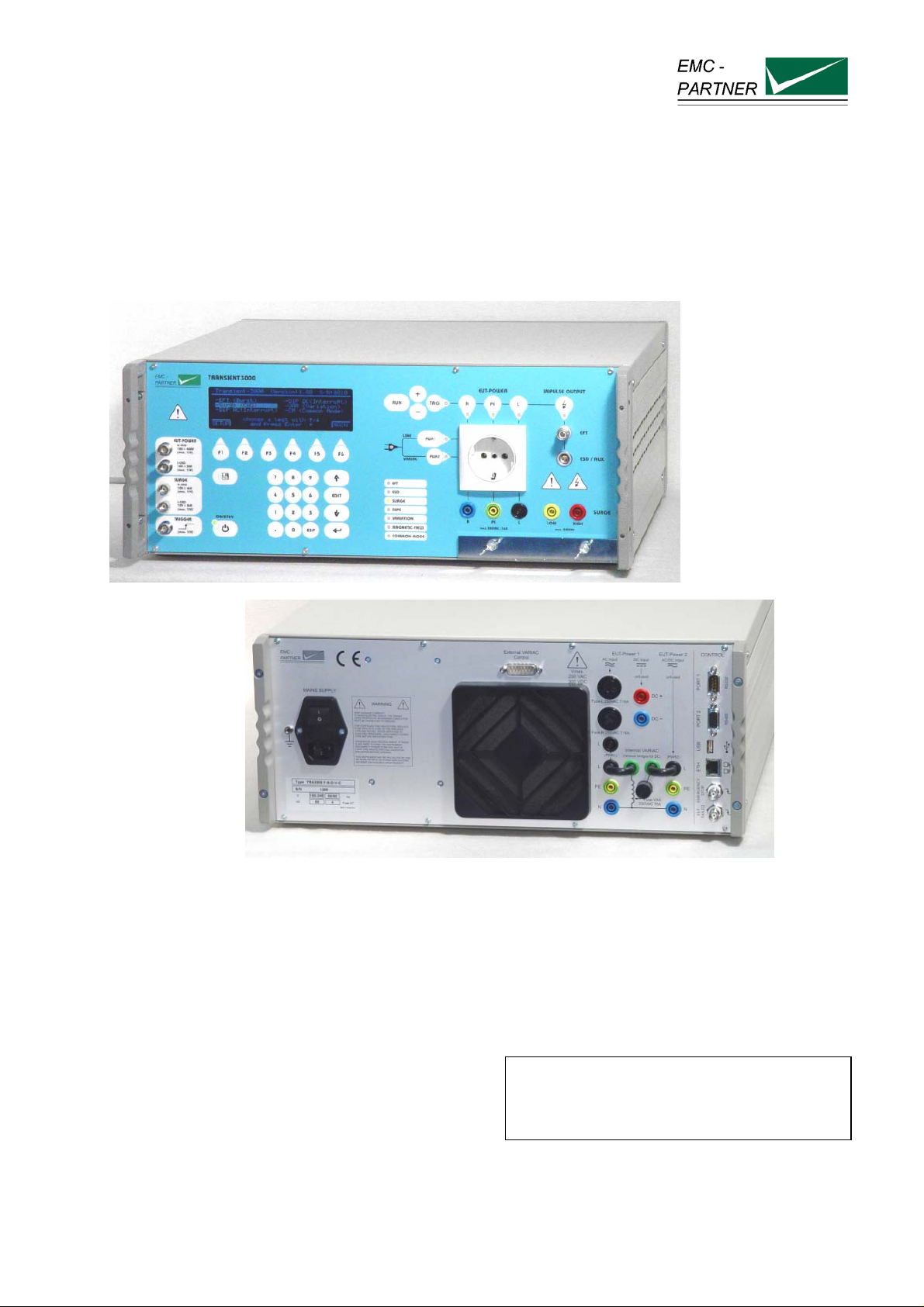
User Manual TRA3000 F-S-D-V-C and EXTTRA3000 E
Title: EMC Test System TRA3000 F-S-D-V-C
Date: 10.07.2009
Product Manager: I. Saner
Service Manager: R. Henz
Division Manager: M. Lutz
Revised: 31. January 2013
TRA3000 F-S-D-V-C
EMC TESTER
E-TRA3000 F-S-D-V-C_E-Manual 1/162
Page 2
TRANSIENT3000
Attention Standard References and User Manual
This user manual provides information necessary for operation of the test
equipment.
Throughout the users manual, standard references are used as an aid to
understanding only.
The relevant standard(s) must be obtained and used in conjunction with
this users manual
Attention contact EMC PARTNER!
Before starting any test, where specifications or limits for a particular
application are not included or could not be found in the EMC PARTNER
documentation (User Manual, Instruction Sheet), users must contact
EMC PARTNER for clarification.
Repair costs arising from incorrect use or failure to clarify an application
with EMC PARTNER remain the responsibility of the user.
Achtung EMC PARTNER kontaktieren!
Wenn für eine Anwendung die notwendigen Informationen: Parameter
oder Limiten nicht aufgeführt sind in der Bedienungsanleitung UM oder in
der Instruktionsanweisung IS, ist der Anwender verpflichtet EMC
PARTNER zu kontaktieren bevor die Prüfung gestartet wird. Anfallende
Reparatur- und Kalibrationskosten bei nicht Beachtung der Limiten in
Bedienungsanleitung / Instruktionsanweisung oder unterlassen der
Rückfrage werden den Kunde belastet.
ATTENTION, veuillez contacter EMC PARTNER!
Lorsque, pour une application, des limites ou des informations
nécessaires ne sont pas mentionnées dans la documentation, l’utilisateur
est tenu de prendre contact avec EMC PARTNER afin de recevoir les
informations supplémentaires avant de commencer les tests.
Les coûts de réparation dus au non respect des limites figurant dans le
mode d’emploi ou dans la notice d’utilisation ainsi que l’omission d’une
demande de précision seront à la charge du client.
Declaration of Conformity
See sheets attached at the end of this user manual:
• Declaration of conformity to product standards
• Declaration of conformity to low voltage directive
• Declaration of conformity to EMC directive
2/162
Page 3

TRANSIENT3000
Contents:
1 DESCRIPTION 9
1.1 The interference sources of the transients 9
1.1.1 Electrostatic discharge ESD 9
1.1.2 Switched inductance EFT (Burst) 9
1.1.3 Indirect lightning SURGE 10
1.1.4 Voltage interruptions, Dips 11
1.1.5 How ESD, EFT, SURGE DIPS differ 11
1.1.6 Common mode disturbances in the frequency range 0 Hz to 150 kHz 12
1.2 Overview of the TRA3000 F-S-D-V-C test system 13
1.2.1 TRA3000 F-S-D-V-C and its versions 13
1.2.2 ESD - TRA3000 System overview 16
1.2.3 EFT - TRA3000 System overview 16
1.2.4 SURGE - TRA3000 System overview 17
1.2.5 DIPS and Interruption - TRA3000 System overview 17
1.2.6 Common Mode - TRA3000 System overview 18
1.2.7 Magnetic fields - TRA3000 System overview IEC 61000-4-8 Ed.2 18
1.2.8 Magnetic fields - TRA3000 System overview IEC 61000-4-9 Ed.1 19
1.3 Technical data of the TRA3000 F-S-D-V-C 20
1.3.1 Electrostatic discharges ESD only valid with EXT-TRA3000 E 20
1.3.2 Electric Fast Transient EFT EXT-TRA3000 F 21
1.3.3 Coupling / De-coupling Network EFT 21
1.3.4 Lightning and switching actions SURGE (IEC 61000-4-5 Ed.2) 22
1.3.5 Coupling / De-coupling Network „CDN-SURGE“ 22
1.3.6 Voltage interruption and Variation with internal Variac EXT-TRA3000 D-V 23
1.3.7 Interruption and Voltage Variation IEC 61000-4-11 Ed.2 with external Variac 24
1.3.8 DIPS circuit in accordance with IEC 61000-4-29 for d.c. power ports. 24
1.3.9 Common mode test with EXT-TRA3000 C 25
1.3.10 Power line limits on EUT power input of TRA3000 26
1.3.11 Synchronisation of TRA3000 to mains frequencies 26
1.3.12 Measuring circuit, measuring outputs 27
1.3.13 Trigger Output Levels 28
1.3.14 Control 28
1.4 Mechanical dimensions 29
1.5 Power Consumption 29
1.6 Included articles, dimensions 29
1.7 Standard accessories 30
2 SAFETY 31
2.1 Safety standard 31
2.2 Climatic Conditions 31
2.3 Precautionary measure during use 32
3/162
Page 4

TRANSIENT3000
Electromagnetic Compatibility 32
2.4
2.5 The manual is an integral part of the equipment. Refer to the manual. 32
2.6 Sécurité 33
2.6.1 Normes de sécurité 33
2.6.2 Conditions climatiques 33
2.6.3 Mesures de précaution lors de l'utilisation 34
2.6.4 Compatibilité électromagnétique 34
2.6.5 Le manuel fait partie intégrante de l'équipement. 34
2.7 Sicherheit 35
2.7.1 Sicherheit Standard 35
2.7.2 Klimatische Bedingungen 35
2.7.3 Vorsichtsmassnahmen während dem Betrieb 36
2.7.4 Elektromagnetische Verträglichkeit 36
2.7.5 Dieses Manual ist Bestandteil von TRA3000 F-S-D-V-C und dessen Testumgebung. 36
3 MECHANICAL STRUCTURE 37
3.1 General 37
3.2 Impulse-forming Networks 38
3.3 Measuring Circuit 39
3.4 Coupling / De-coupling Network CDN 39
3.5 EUT power supply at DIPS 39
4 CONTROL PANEL 41
4.1 Front panel of the TRA3000 F-S-D-V-C 41
4.1.1 Control part 41
4.1.2 Operation panel 44
4.2 Rear Panel of the TRA3000 F-S-D-V-C 46
5 PREPARATION FOR OPERATION 51
5.1 Attention, Refer to Manual 51
5.2 Operators and Service Personnel 51
5.3 Checks before operation 51
5.3.1 Optical verification of the TRA3000 F-S-D-V-C 51
5.3.2 Power source check 51
5.3.3 Connecting the TRA3000 F-S-D-V-C to the power line 51
5.3.4 EUT Power, Power source for the EUT 52
5.3.5 EUT Power, supply of the EUT with voltages differ from the public power line (Variac) 53
5.4 EUT Power, supply of the EUT with dc 54
5.4.1 TRA3000 not equipped with EXT-TRA3000 D: 55
4/162
Page 5

TRANSIENT3000
TRA3000 equipped with EXT-TRA3000 D 55
5.4.2
5.4.3 DIP DC (Interrupt) without PS3 power supply source of EMC PARTNER 55
5.4.4 Example 56
5.5 Hints for the test set up according to IEC standards 57
5.5.1 Test set up EFT 57
5.5.2 ESD test set up 58
5.5.3 Test set up SURGE 59
5.5.4 Test set-up for table top equipment 61
5.6 Practical testing sequence 62
6 TESTING WITH THE TRA3000 F-S-D-V-C 63
6.1 Quick start of the TRA3000 F-S-D-V-C 63
6.1.1 Selection of a language: Deutsch, François, Italian, Espagnol and Beep function 65
6.1.2 Protocol possibilities 66
6.1.3 EUT - Power and EUT - Control 67
6.2 Editing test parameters 68
6.2.1 Overview of programmable test with the TRA3000 F-S-D-V-C 68
6.2.2 Nominal values setting 71
6.2.3 Editing „Ramp“ 82
6.3 EMC test operation „RUN Mode“ 90
6.4 Operating System Displays 95
6.4.1 Rolling information lines 95
6.4.2 Service access and firmware upload 96
6.4.3 Web Server 97
6.5 Protocol Management 98
6.5.1 Customizing the Protocol Header 98
6.5.2 Optimizing Protocol storage 99
7 MAINTENANCE AND SERVICING 103
7.1 Maintenance 103
7.2 Cleaning front and rearplate 103
7.3 Verification versus Calibration 103
7.3.1 Verification Example IEC 61000-4-4 Ed.2 103
7.3.2 Calibration Example IEC 61000-4-4 Ed.2 103
7.4 Verification of the TRA3000 F-S-D-V-C by the user 103
7.4.1 EFT 103
7.4.2 ESD 104
7.4.3 SURGE 104
7.4.4 Interruption 104
7.4.5 Variation 104
7.5 Calibration of the TRA3000 F-S-D-V-C by EMC PARTNER AG 105
5/162
Page 6

TRANSIENT3000
Service of SPD Surge Protective device 105
7.6
8 WHAT MUST BE DONE FOLLOWING FAILED OPERATION 107
8.1.1 Error caused by incorrect inputs „Generator not ready for run“ 107
8.1.2 Error caused by running problem „Generator stopped“ 108
8.1.3 Failure based on error at the generator „Hardware error“ 109
8.2 Service; Repairs 110
8.2.1 Service Flowchart of TRA3000 System: 110
8.2.2 Data Transfer via UBS Stick 111
8.3 Spare parts list 111
8.4 Check before you contact the service of EMCP 111
8.4.1 Fuses 111
8.4.2 Seltests 112
8.4.3 System Reset (Software) 113
8.5 Service department of EMC PARTNER AG 114
9 PACKAGING AND TRANSPORT 115
9.1 Packaging 115
9.2 Transport 115
10 RECYCLING / DISPOSAL 117
10.1 RoHS directive 2002/95/EG 117
10.2 WEEE directive 2002/96/EG 117
10.3 Information for dismantling 117
10.4 Parts which can be recycled 117
10.5 Parts which can not be recycled 117
11 ACCESSORIES 119
11.1 TRA3000 F-S-D-V-C 119
11.1.1 Accessories TRA 120
12 REMOTE PORTS 125
12.1 General 125
12.1.1 Ethernet port setting on TRA3000 125
12.1.2 IP address setting on PC 125
12.1.3 Technical Data of the RS 232C serial port 126
12.1.4 Local or Remote Control 126
12.1.5 Remote Control 127
6/162
Page 7

TRANSIENT3000
Organisation of TRA3000 F-S-D-V-C Remote-Control Commands 127
12.2
12.2.1 Syntax of the Commands 127
12.2.2 Set-up Commands: 127
12.2.3 Inquire Commands 128
12.2.4 Failure messages remote control: 128
12.3 Remote Control Command set 129
12.4 Overview of TRA3000 F-S-D-V-C Commands 136
12.5 Software "GENECS" for TRA3000 F-S-D-V-C Remote Control 141
12.5.1 Setup GENECS 141
12.5.2 GENECS Windows 141
13 APPENDIX AND CORRECTIONS 143
13.1 Appendix 143
13.1.1 Definition of the EFT Waveform 143
13.1.2 Definition of the ESD Waveform 144
13.1.3 Definition of the SURGE Waveform 145
13.1.4 DIPS Specification 146
13.1.5 VARIATION Specification IEC 61000-4-11 Ed.1 147
13.1.6 VARIATION Specification IEC 61000-4-11 Ed.2 148
13.2 Correction 149
13.2.1 Declaration of conformity to the EMC directive 2004/108/EC 149
13.2.2 Declaration of conformity to the LV directive 2006/95/EC 149
13.2.3 Declaration of conformity to the Basic Standards 149
14 GLOSSARY 151
15 INDEX 153
7/162
Page 8

TRANSIENT3000
8/162
Page 9
1 Description
1.1 The interference sources of the transients
1.1.1 Electrostatic discharge ESD
Electro Static Discharge IEC 61000-4-2 Ed.2
What causes electrostatic discharges?
A person becomes electrostatically charged by walking over an insulating floor surface. The capacity of the
body can be charged to several kilovolts (1000 V). This capacity is discharged when contact is made with
an electronic unit or system. The discharge is visible as a spark in many cases and can be felt by person
concerned, who gets a „shock“. The discharges are harmless to humans, but not to sensitive, modern
electronic equipment. The resulting current causes interference in the units or can make entire systems
„crash“.
For over 25 years it has been known to the electrical industry that electrostatic discharges as encountered
every day can have a disastrous effect on electronic equipment.
The cost of damage caused by ESD is difficult to assess, but amounts to billions of dollars worldwide.
The areas most affected are:
• manufacturing of integrated circuits (chips).
• the chemical industry, e.g. by explosion, fires caused by the sparks from electrostatic discharges.
• malfunctioning of process control with the secondary damage costs.
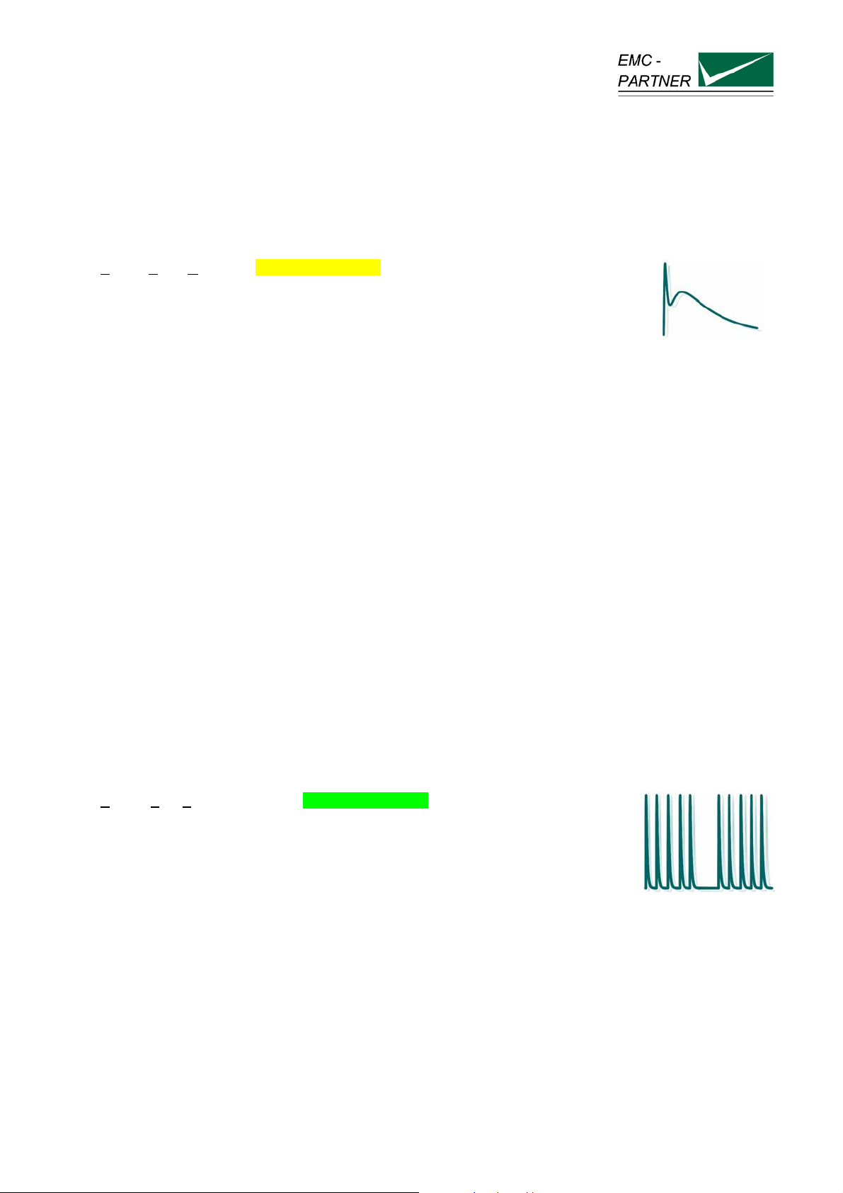
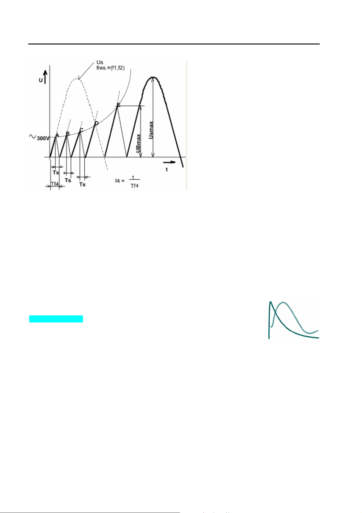
1.1.2 Switched inductance EFT (Burst)
Electric Fast Transient or Burst. IEC 61000-4-4 Ed.2
Industrial measurement and control equipment practically always operates in conjunction with conventional
control units (relays, contactors). Fluorescent lamp ballast units, insufficiently suppressed coffee grinders,
vacuum cleaners, drilling machines, hair dryers, universal motors, etc. can be found everywhere in the
power supply system. All these, primarily inductive loads, produce interference when switched on and off. A
wide range of switching transients, also called bursts, are produced with the following waveform.
E-TRA3000 F-S-D-V-C_E-Manual 9/162
Page 10
TRANSIENT3000
Figure: 1.0.1.2
The parameters which define the
burst are:
- Rise time of the spike Ts in ns
- Repetition frequency f4 in the range of kHz up to MHz
- Energy, some mJ
- Voltage amplitude UBmax. up to some kV
- Duration of a burst several milliseconds
The different EFT sources generate different burst waveforms. A typical burst waveform is shown in the
figure above.
The impedance of the EFT source is generally high, therefore the capacitance of connected cables
influences the rise time.
1.1.3 Indirect lightning SURGE
SURGE are transients with a high energy, relatively low frequency content up to some
.
kV
IEC 61000-4-5 Ed.2
Lightning is a daily event and occurs about 8 million times in approximately 44,000 storm centres
throughout the world. That is in the order of 100 discharges per second. Measuring and recording
equipment in aircraft registers one lightning strike for every 1,000 flying hours.
Product assembly and finishing in many industries depends on modern electronics. The most frequent
cause of damage is overvoltage, caused either by switching action in the equipment itself or by
atmospheric discharges such as lightning. In order that the overvoltages do not destroy the electronic
equipment, protection elements and circuits are placed at the inputs and outputs of electronic equipment.
Consumer electronic devices, such as antenna ports on television sets, telephones, faxes, can also be
influenced by atmospheric discharges. The disturbances are mostly tolerable because of their relatively low
occurrence. To protect such equipment from damage protection elements and circuits are installed. Tests
must be carried out to determine whether these protective circuits are really effective.
Beside lightning, switching action can also generate high energy impulses.
10/162
Page 11
TRANSIENT3000
1.1.4 Voltage interruptions, Dips
DIPS means a sudden reduction of the voltage at a point in the electrical system,
followed by voltage recovery after a short period of time from a few cycles to a few
seconds.
IEC 61000-4-11 Ed.2
Voltage failures occur following switching operations, short-circuits, fuses blowing and when running up
heavy loads. These are man-made faults, produced unintentionally, and include operation of domestic
appliances, electronically controlled machine tools, switching operations in the public lighting system,
economy lamps, etc.
The quality of the electrical power supply is increasingly becoming a central topic of discussion.
Interference sources in the mains, caused by electronic power control using non-linear components such
as thyristors are increasing. These devices are used in domestic appliances, such as hotplates, heating
units, washing machines, television sets, economy lamps, PCs and industrial systems with speedcontrolled drives. Simultaneously an increase in electronic systems sensitive to interference is apparent in
all sectors of the electrical power system.
In order to achieve electromagnetic compatibility, both the interaction of the electrical equipment connected
to the supply and its noise immunity must be determined.
The electromagnetic compatibility of electronic equipment must be guaranteed e. g. Europe Union 31.
December 1995.
1.1.5 How ESD, EFT, SURGE DIPS differ
Characteristics Static
Phenomenon
Voltage U
discharges Switched
"ESD" "EFT Burst" "Surge" "DIPS"
up to 15 kV up to 4 kV up to 4 kV supply source
Energy at maximum
approx. 10 mJ 300 mJ 300 J -
inductance
Lightning.
switching actions
Mains
Interruptions
voltage
voltage
Repetition rate
Application to the
different ports
upper limit
Single event Multiple event 5
kHz
Touchable metallic
part ( enclosure
ports)
AC/DC ports,
Signal and data
lines
Maximum 6
Impulse / minutes
AC/DC ports,
Signal and data
lines
supply source
frequency
AC/DC ports
approx.. 1 GHz approx. 200 MHz approx. 350 kHz approx. 100 kHz
frequency
impulse waveform
IEC 61000-4-2 Ed.2
IEC 61000-4-4 Ed.2
IEC 61000-4-5 Ed.2
IEC 61000-4-11 Ed.2
The overview of „How ESD,EFT, SURGE,DIPS differ“ shows that all four test have to be carried out
because the frequency content and energy of the four transient tests are different.
11/162
Page 12

TRANSIENT3000
1.1.6 Common mode disturbances in the frequency range 0 Hz to 150 kHz
IEC 61000-4-16 Ed.1 Amd.2
The conducted, common mode disturbances at mains frequency and its harmonics may be generated by
faults on the mains power distribution system and leakage currents flowing into the earth system. The d.c.
power supply network used in industrial, electrical plants and telecommunication centres may also
generate d.c. common mode disturbances, particularly when either the positive or negative terminal is
connected to earth.
Electrified railways will also generate disturbances at their frequency of operation (typically 16
2/3 Hz).
The induced disturbances are described in detail in IEC 61000-2-3 and IEC 61000-2-5. The different types
of disturbances may be present simultaneously but at different levels.
Furthermore, if the power system develops a fault, the disturbance levels may be up to 10 times the
reference levels given for normal operating conditions, however the fault condition disturbances are
typically present for short durations only (up to about 1 s).
The disturbances at mains frequency and harmonics may affect signal ports of equipment where
insufficient common mode rejection is available. Disturbances up to 1-2 kHz are mainly due to the
harmonics of the power mains.
At higher frequencies the disturbances are mostly related to power electronic equipment, which may
produce switching currents involving the ground system, giving rise to conducted, common mode
disturbances.
12/162
Page 13
TRANSIENT3000
1.2 Overview of the TRA3000 F-S-D-V-C test system
1.2.1 TRA3000 F-S-D-V-C and its versions
The tester TRA3000 F-S-D-V-C simulates transients of different interference sources. Such as: indirect
lightning in electronic systems, human body electrostatic discharges, switched inductance (Burst), power
supply interruptions and variations and common mode disturbance.
The test system TRA3000 F-S-D-V-C with accessories fulfils all requirements of the IEC basic standards
IEC 61000-4-2 Ed.2 (ESD); 61000-4-4 Ed.2 (EFT); 61000-4-5 Ed.2 (SURGE) without 10/700 µs impulse;
61000-4-11 Ed.2 (Interruption and Variations), and with accessories 61000-4-8 Ed.2 (Magnetic field
50/60Hz) and 61000-4-9 Ed.1 (Magnetic field SURGE), Common mode disturbance IEC 61000-4-16 Ed.1
Amd.2, 61000-4-29 Ed.1 dips and interruption on d.c. and IEC 61000-4-34, DIPS and Interruption >16A
per phase.
If not all transient test are needed, the TRA3000 F-S-D-V-C tester is also available in various versions, with
the possibility to upgrade the tester later to a full TRA3000 F-S-D-V-C test system.
The upgrade can be made by a customer. Mounting instruction (IS) will be delivered with
the relevant module.
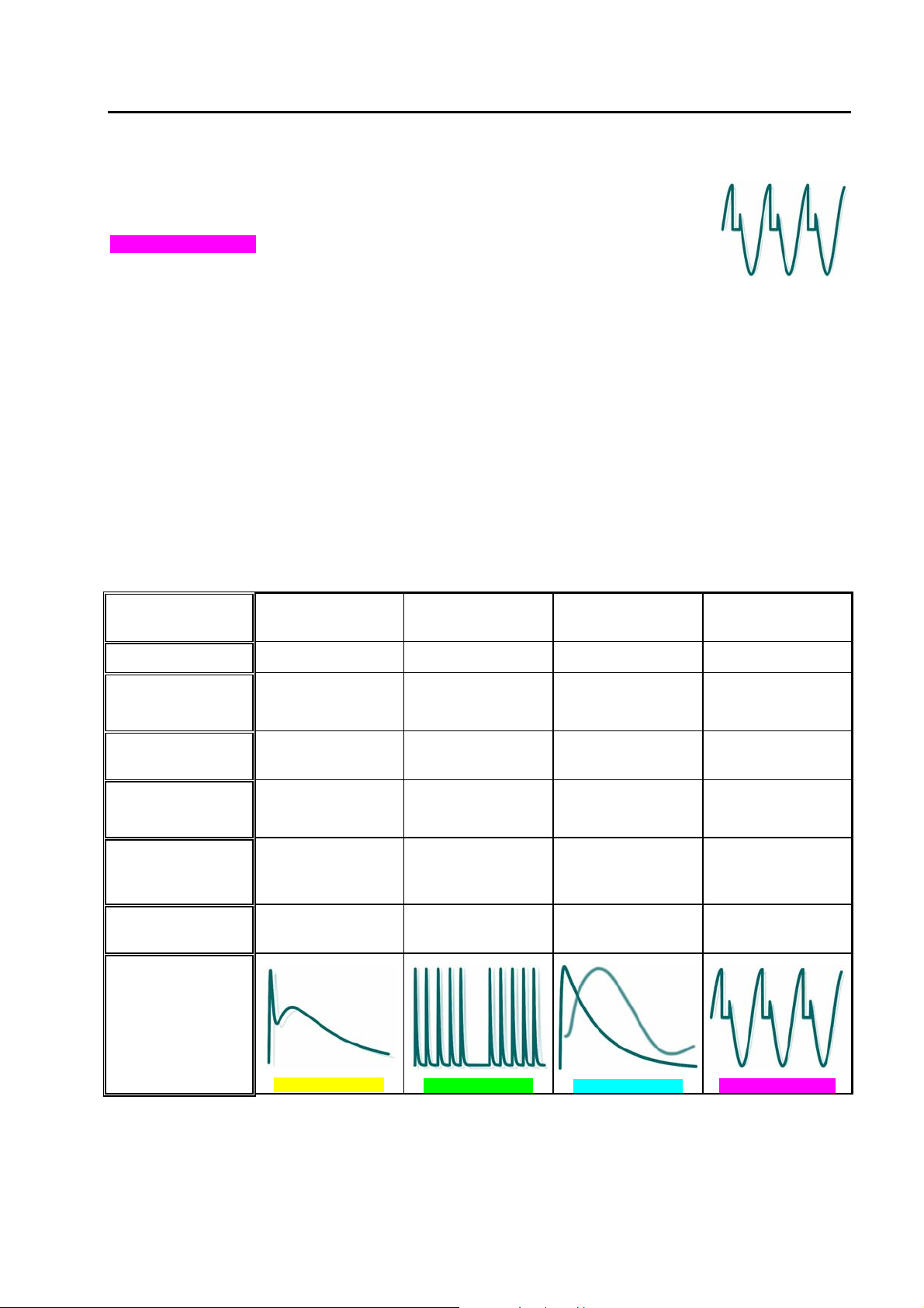
The following EXT-TRA units are available:
EXT-TRA3000 E (ESD)
EXT-TRA3000 F (Electrical Fast Transient, Burst)
Installing instruction of EXTTRA3000 E can be found in the
Instruction Sheet (IS), delivered
with the EXT-TRA3000 E.
Installing instruction of EXTTRA3000 F can be found in the
Instruction Sheet (IS), delivered
with the EXT-TRA3000 F.
13/162
Page 14
TRANSIENT3000
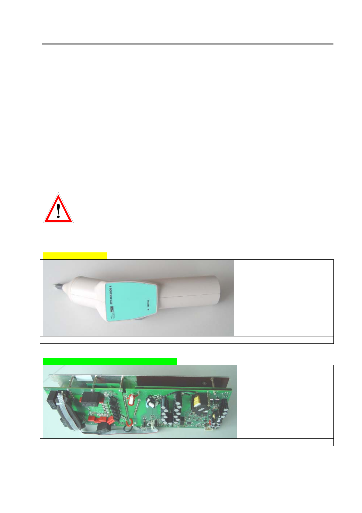
EXT-TRA3000 S (Surge)
Installing instruction of EXTTRA3000 S can be found in the
Instruction Sheet (IS), delivered
with the EXT-TRA3000 S.
EXT-TRA3000 D (DIPS)
Installing instruction of EXTTRA3000 D can be found in the
Instruction Sheet (IS), delivered
with the EXT-TRA3000 D.
When no EXT-TRA3000 V is
installed in the TRA3000
together with the EXTTRA3000 D, than the black
MC bridge must be inserted
on the rear panel on PWR2
between L and PE.
14/162
Page 15
TRANSIENT3000
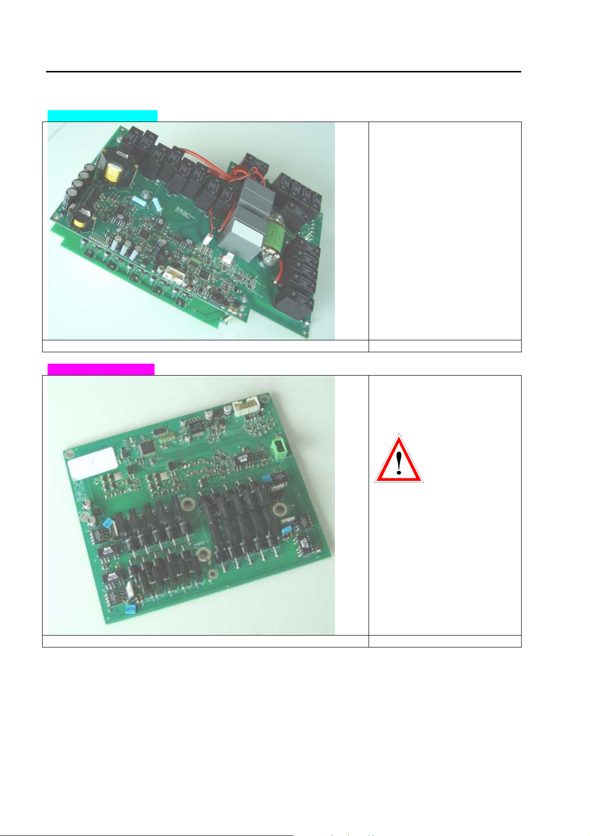
EXT-TRA3000 V (Variation)
Installing instruction of EXTTRA3000 V can be found in the
Instruction Sheet (IS), delivered
with the EXT-TRA3000 V.
EXT-TRA3000 C (Common Mode Disturbance)
Installing instruction of EXTTRA3000 C can be found in the
Instruction Sheet (IS), delivered
with the EXT-TRA3000 C.
Each EXT-TRA3000 is delivered with a calibration report.
The TRA3000 F-S-D-V contains a single-phase coupling / de-coupling network, which allows a controlled
superposition of the transients onto a power supply line.
All transients are generated at the same EUT power output, therefore a true single port test is possible. The
TRA3000 F-S-D-V-C allows the automated switching of coupling paths and the programming of a large
range of test sequences.
The tester TRA3000 F-S-D-V-C is a stand-alone equipment for automated EMC test without a PC.
15/162
Page 16
TRANSIENT3000
1.2.2 ESD - TRA3000 System overview
Vertical Coupling
Plate
ESD-VCP50
GENECS TRA
TRA3000
EXT-TRA3000-E
150pF / 330 ohm
EUT
Calibration Devices (ESD-Target 2, ESD VERI-V)
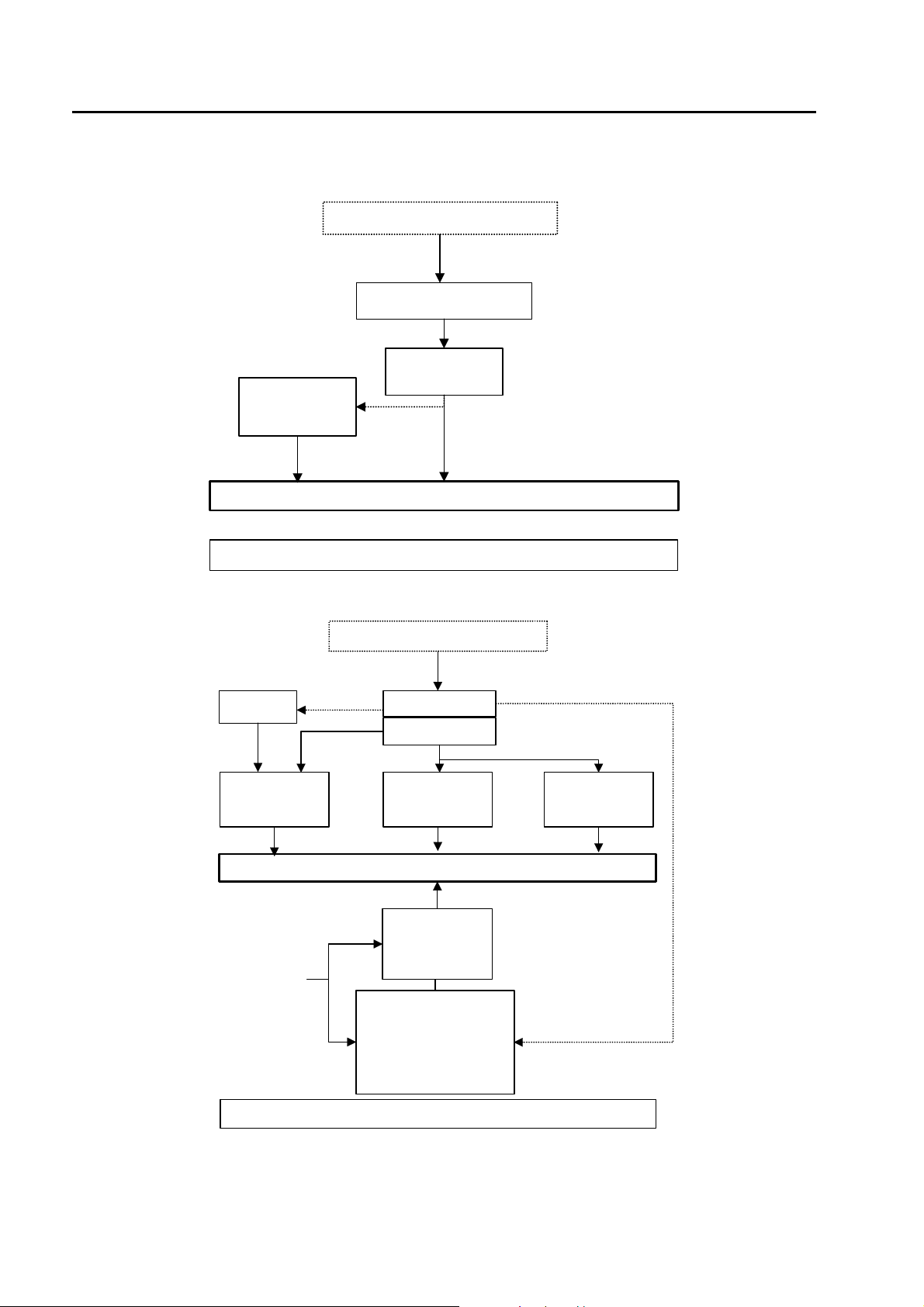
1.2.3 EFT - TRA3000 System overview
PS3
Single Phase
AC / DC Power
Direct
Three Phase
EUT Power
GENECS-TRA
TRA3000
EXT-TRA3000-F
Differential Output
Adpater CN-BALUN
EUT
Manual Three
Phase
AC / DC Power
CDN2000-06-32
Automatic Three Phase
AC / DC Power
CDN2000A-06-32
CDN2000A-06-63
CDN-A-3P100-480 F
CDN-A-3P100-690 F
Data Lines
CN-EFT1000
16/162
Calibration Devices (VERI50-EFT, VERI1K-EFT, Adapter EFT-CDN)
Page 17
TRANSIENT3000
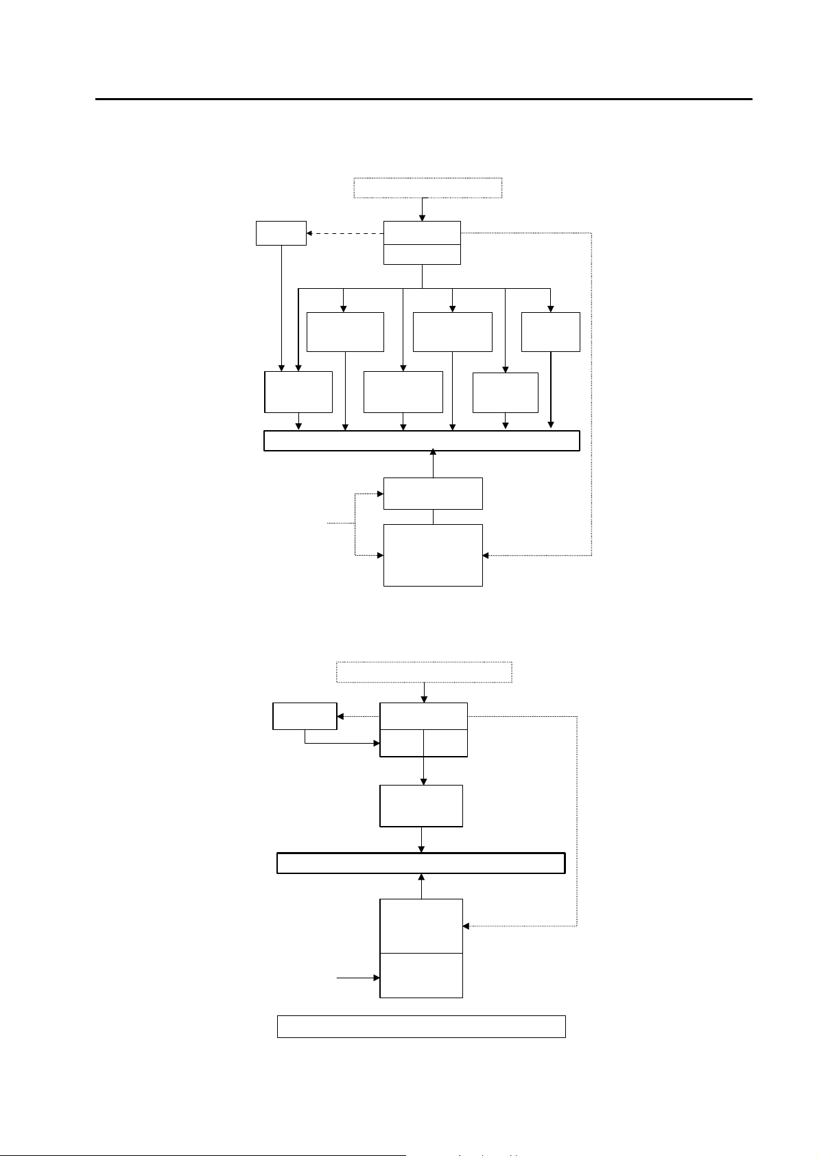
1.2.4 SURGE - TRA3000 System overview
GENECS-TRA
PS3
Railway Application
Single Phase
AC / DC Power
Direct
Option
NW-TRA-RAIL
TRA3000
EXT-TRA3000-S
Telecom Lines
Coupling
Decoupling Modules
DN & CN2000-22-5
Balanced
CDN-UTP
EUT
Manual Three Phase
CDN2000-06-32
Three Phase
EUT Power
Automatic T h r ee Phase
CDN2000A-06-32
CDN2000A-06-63
CDN-A-3P100-480 F-S
CDN-A-3P100-690 F-S
1.2.5 DIPS and Interruption - TRA3000 System overview
Direct Injection
Probe
CN2000TT
Un-balanced
Lines
CDN-KIT1000
GENECS-TRA
VAR-EXT1000
or PS3
TRA3000
EXT-TRA
3000-D
Single Phase
AC Power
Direct
EXT-TRA
3000-V
EUT
Three Phase
Interrupt AC / DC
Power
PFS32 / PFS63 /
PFS75
Three Phase
Three Phase
EUT Power
DIPS AC Power
SRC32 / SRC63 /
SRC75
Calibration Device (VERI- DIPS)
17/162
Page 18
TRANSIENT3000
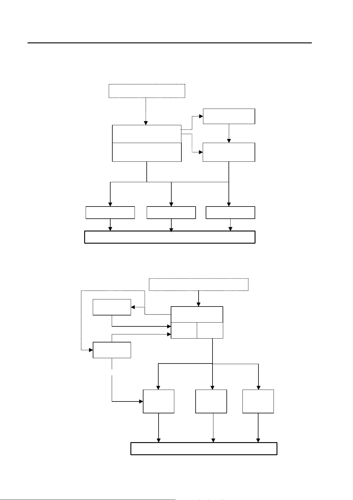
1.2.6 Common Mode - TRA3000 System overview
GENECS-TRA
TRA3000
PS3
EXT-TRA3000-C
CN16AC
EXT-TRA3000-C
SHORT
EUT
1.2.7 Magnetic fields - TRA3000 System overview IEC 61000-4-8 Ed.2
GENECS TRA
VAR-EXT1000
TRA3000
CN16TCN16
18/162
PS3
16.7Hz
EXT-TRA
3000-D
MF1000-1 MF1000-2 MF1000-3
EXT-TRA
3000-V
EUT
Page 19
TRANSIENT3000
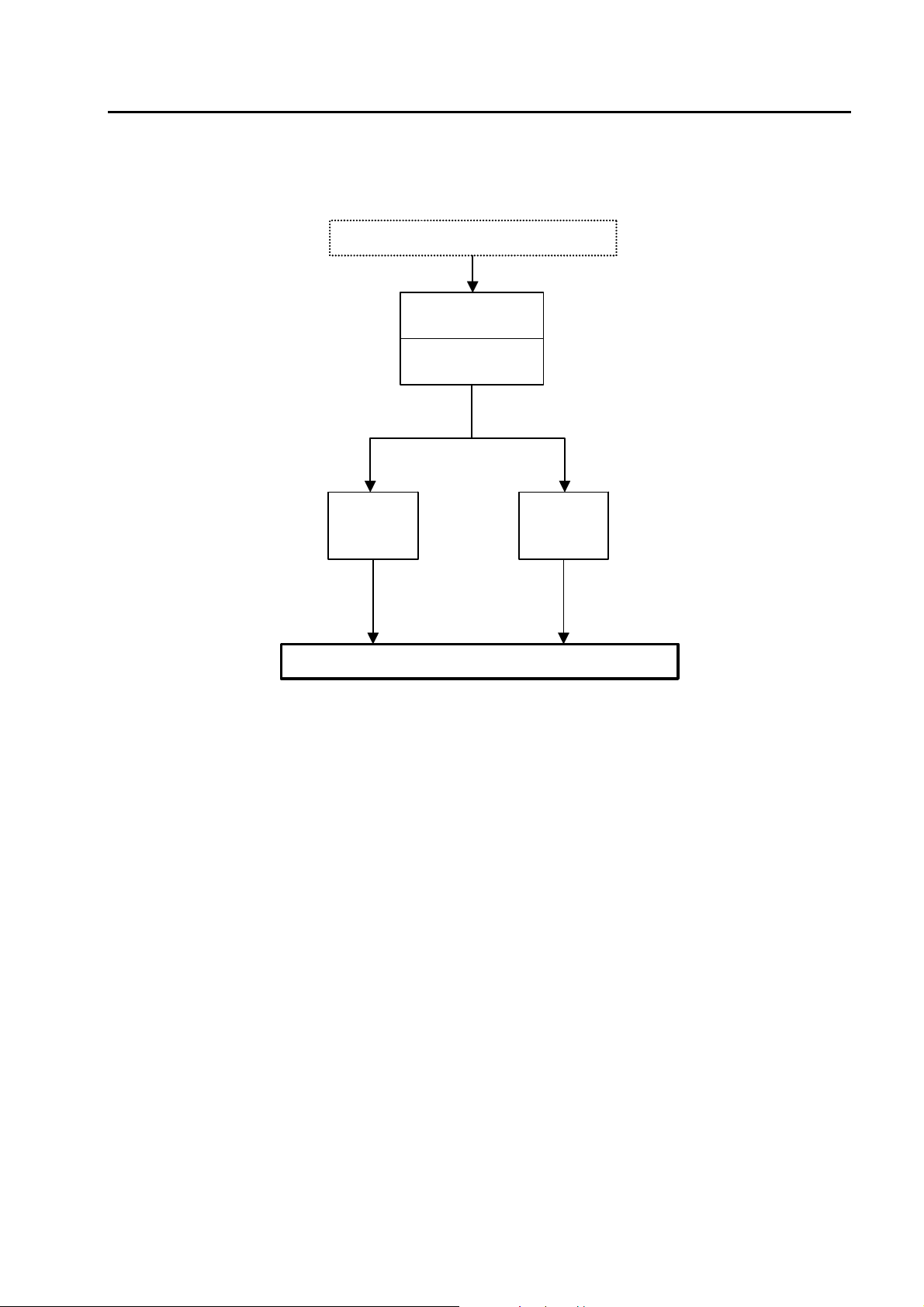
1.2.8 Magnetic fields - TRA3000 System overview IEC 61000-4-9 Ed.1
GENECS-TRA
TRA3000
EXT-TRA3000-S
MF1000-1 MF1000-2
EUT
19/162
Page 20

TRANSIENT3000
1.3 Technical data of the TRA3000 F-S-D-V-C
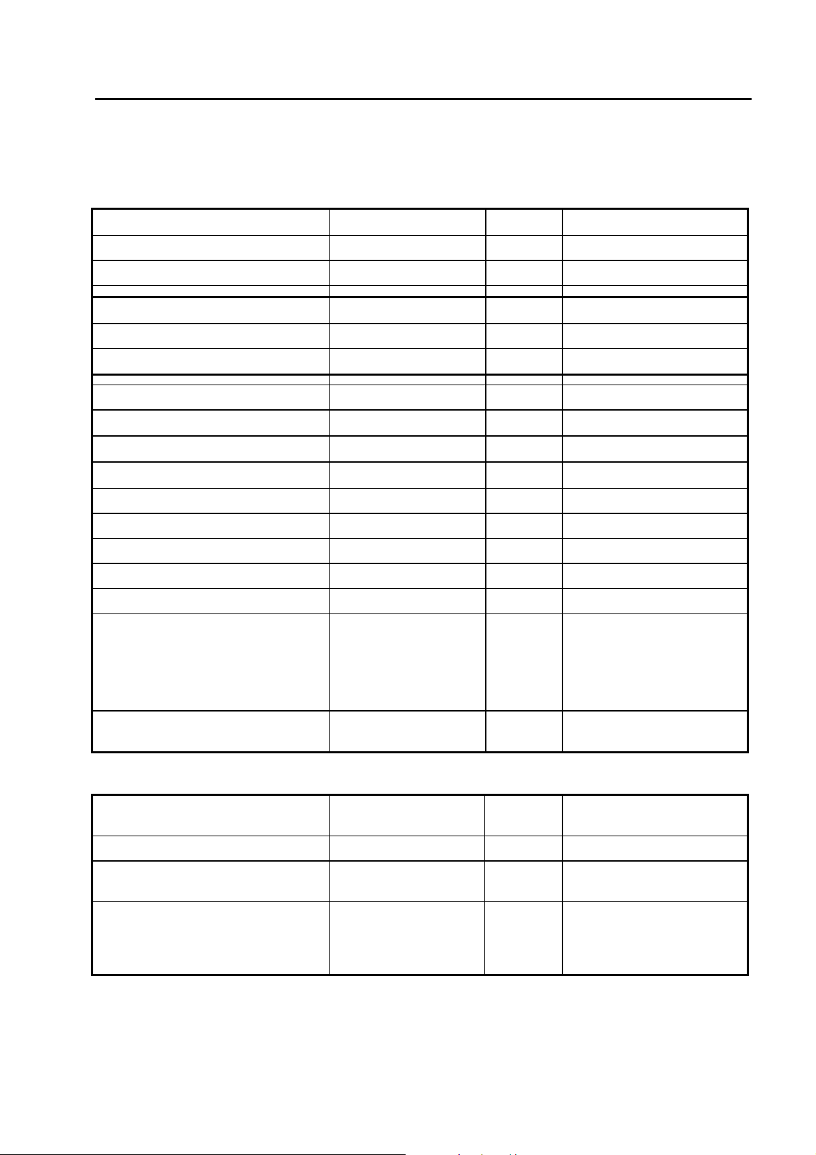
1.3.1 Electrostatic discharges ESD only valid with EXT-TRA3000 E
Energy storage capacitance 150 pF
Discharge resistance
Charging resistance
Holding time (drop to 95%) better than 5 s
Current rise time, 2 Ω load
Definition of current waveform:
Current amplitude at 30 ns 4 to 16 A ± 30%
Current amplitude at 60 ns 2 to 8 A ± 30%
Voltage range „air discharge“ 2 to 15 kV ± 10%
Voltage range „contact discharge“ 2 to 10 kV ± 10%
First current amplitude into 2 Ω
„contact discharge“
Polarity positive / negative;
Number of discharges
330 Ω
54 MΩ
0.8 ns ± 25% See 6.1
7,5 to 30 A ± 15%
automatic switchover
-preselectable
IEC 61000-4-2 Ed.2
1 to 29’999
Detection of the number of
discharges
Ramps voltage amplitude
Reporting test sequence with the
Discharge modes: -Air discharge
Repetition of the discharges 0.05 up to 30 s
-count „every pulse“
-count „discharge only“.
Only the impulses
whereas the voltage of
the discharge capacitor
tropes lower then 10%
of the charging voltage
are counted.
changes from shot to
shot, alternate polarity
number of discharges
-Voltage amplitude
-Polarity
-Contact discharge
Single discharge „Man“
20/162
Page 21
TRANSIENT3000
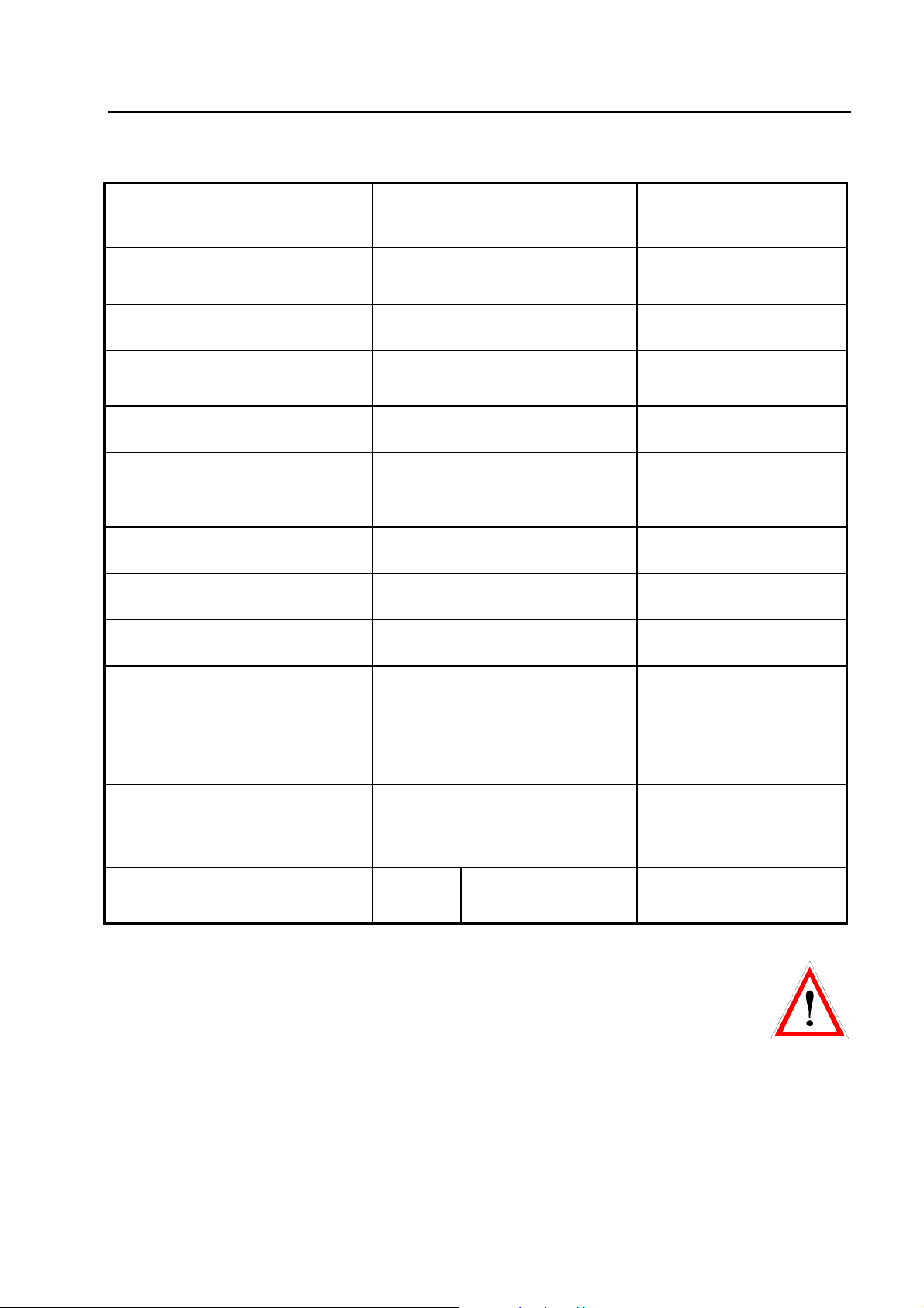
1.3.2 Electric Fast Transient EFT EXT-TRA3000 F
Voltage waveform into 50 Ω:
Risetime 5 ns ± 30%
Half time value 50 ns ± 30%
Voltage waveform into 1000 Ω:
Risetime 5 ns ± 30%
Half time value 50 ns - 15 ns + 100 ns
Adjustable voltage range 250 V to 4400 V
Voltage amplitude into 50 Ω
Voltage amplitude into 1000 Ω
Source impedance
Spike frequency 1 kHz up to 1 MHz
Maximum Spikes per seconds 8’000 at 1000 V 1000 at 4000 V
Burst duration 0,001 ms up to 30 ms
Burst repetition 1 ms up to 1000 ms
Polarity positive / negative
Impulse Output IEC 61000-4-4 Ed.2
125 V to 2000 V ± 10%
250 V to 4000 V ± 20%
50 Ω
± 10%
Ramps -Voltage
-Spike frequency
-Synchronisation
-Burst duration
High voltage output 10 nF decoupled max.
450 V ac
1.3.3 Coupling / De-coupling Network EFT
Maximum continuous EUT power
supply voltage
Maximum allowed continuous current 16 A
Spike waveform superimposed onto
the lines of the EUT power supply
Coupling paths:
280 V ac 50/60 Hz
within the tolerances as
above
L-GND; N-GND, PEGND, L+N+PE - GND
L+N - GND; L+PE GND; N+PE - GND
IEC 61000-4-4 Ed.1 and
Ed.2 Amd.1
21/162
Page 22

TRANSIENT3000
1.3.4 Lightning and switching actions SURGE (IEC 61000-4-5 Ed.2)
Waveform at no load : Impulse output See 6.1
Front time 1.2 µs ± 30%
Time to half value 50 µs ± 20%
Waveform at short circuit:
Front time 8 µs ± 20%
Time to half value 20 µs ± 20%
Preselectable voltage range 220V to 4100 V
Open circuit output range 250 V to 4000 V ± 10% Short circuit output current 125 A to 2000 A ± 10%
Output impedance Umax / Imax
Polarity positive / negative / altn
Ramps -Voltage
High voltage output "low" maximum voltage
Time between successive shots 3 s 5s at 4000 V
2 Ω
-Polarity
-Synchronisation
between „low“ and
earth 260 V ac
1.3.5 Coupling / De-coupling Network „CDN-SURGE“
Maximum allowed continuous
voltage phase neutral
Coupling path phase- earth
Coupling path neutral - earth
Coupling path phase - neutral 18 µF (L-N)
280 V ac 50/60 Hz 16A
9 µF + 10 Ω
9 µF + 10 Ω
(L-PE)
(N-PE)
Coupling modes:
Attention ! The CDN-SURGE 1,2 / 50; 8 / 20 µs is designed for maximum power consumption at 280V
rms 50/60Hz and a coupling capacitance of 18 µF.
If using coupling de-coupling networks from other manufacturers, the maximum power dissipation of the
TRA3000 F-S-D-V-C must be considered. Power Line voltages higher than specified can destroy the
impulse forming devices in the TRA3000 F-S-D-V-C. Please contact EMC PARTNER AG or a
representative before using an unknown coupling network.
22/162
L-N; L-PE; N-PE,
automatic coupling path
switching
Page 23
TRANSIENT3000
1.3.6 Voltage interruption and Variation with internal Variac EXT-TRA3000 D-V
Voltage range 0 to 260 V when EUT
power input voltage is
230V
Frequency range without variac DC up to 400 Hz external Source
Frequency range with variac involved 48 Hz to 60 Hz external Source
Nominal current 16A without internal
Variac involved
Interruption with internal variac and
linear load
Inrush current 500 A Peak - 0%,
Interruption time 50 µs to 30 s phase angle selectable
Amplitude of the interruptions continuously selectable
Phase angle for turn ON and OFF of
the EUT. Selectable in range
Voltage variation with the internal
variac
Voltage variation with external variac 0 to 110 % maximum.
maximum 12 A
maximum 16 A
from 0 to 100 %
0 to 360° ± 5°
0 to 110 % maximum.
5A
16 A
EUT
Power
< 5s
+30%
IEC: 0 %, 40 %, 70 %, 80%
± 20% 2 s to 30000 s
± 20% 2 s to 30000 s
Depending on the EUT
power voltage
< 300 ms
Less than 1 period
More than one period
d.c. interruption
Ramps -Voltage
Interruption for all kind of loads
UT= voltage at EUT Power 1
Interruption within one
period. Input as angle
Interruption longer then
one period. Input in ms
Input in ms
-Synchronisation angle
-Interruption time
DIP
100 %
% UT
0 %
0 to 16 A
For interruptions of 0 to 100% and 100% to 0% the internal Variac is not involved, therefore the test
can be carried out up to 16 A. For interruption with UT =EUT Power 1 voltage not zero, the internal
variac limits the EUT power current. The maximum allowed current values are listed in the table on
the next page. Please be aware that different types of loads influence the maximum current.
23/162
Page 24
TRANSIENT3000
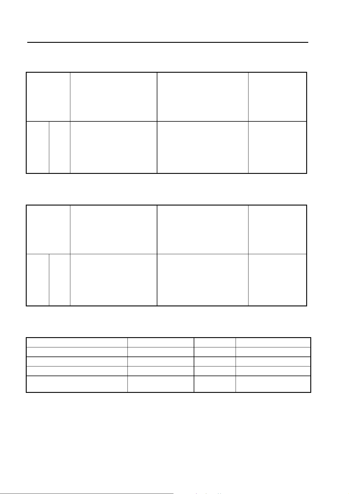
With internal Variac:
Types of
loads:
switching
from to
UT
100 %
100%
100%
100%
Note: all values apply for switching time at %UT< 5 s
% UT
0 %
80%
70%
40%
Variable power
maximum
With reduction of the voltage
the current is also reduced.
Examples: Ohmic -, inductive -,
capacitive -, mixed loads
current range r.m.s
consumption
2.6 kW at UT 230 V.
0 to 16A
0 to 10 A
0 to 9 A
0 to 5 A
Constant power consumption
maximum
With reduction of the voltage the
current is increased.
Example: switched power supply
1,2 kW at UT = 220V.
current range r.m.s
0 to 16A
0 to 5A
0 to 6 A
0 to 10 A
voltage change in
% of UT
change 0 to 100 %
UT= voltage at EUT
Power 1
1.3.7 Interruption and Voltage Variation IEC 61000-4-11 Ed.2 with external Variac
Types of
loads:
switching
from to
Variable power
maximum
With reduction of the voltage
the current is also reduced.
Examples: Ohmic -, inductive -,
capacitive -, mixed loads
consumption
3.7 kW at UT 230 V.
Constant power consumption
maximum
With reduction of the voltage the
current is increased.
Example: switched power supply
3,7 kW at UT = 220V.
voltage change in
% of UT
change 0 to 100 %
UT= voltage at EUT
Power 1
at current
% of UT
0.7 %
4%
4%
5%
at current
UT
100 %
100%
100%
100%
Note: all values apply for switching time at %UT< 5 s
% UT
0 %
80%
70%
40%
current range r.m.s
0 to 16A
0 to 12.8 A
0 to 11.2 A
0 to 6.5 A
current range r.m.s
0 to 16A
0 to 20A
0 to 23 A
0 to 40 A
% of UT
0.7 %
4%
4%
5%
1.3.8 DIPS circuit in accordance with IEC 61000-4-29 for d.c. power ports.
Voltage range d.c. 20 to max. 300 V EUT Power
Current range 0 up to 16A 10A at 300V See derating curve of PS3
Inrush current capability at 110 V 220A Peak - 0%, +30% See 6.1.1
Interruption time 1ms up to 29999 ms
Rise and fall time at 100 Ohm load between 1 µs and 50
µs
See 6.1
IEC 61000-4-29 page 19:
The use of a generator with higher or lower voltage/current capability is allowed provided that the other
specifications are preserved. The test generator steady state power/current capability shall be at least 20%
greater than the EUT power/current ratings.
24/162
Page 25
TRANSIENT3000
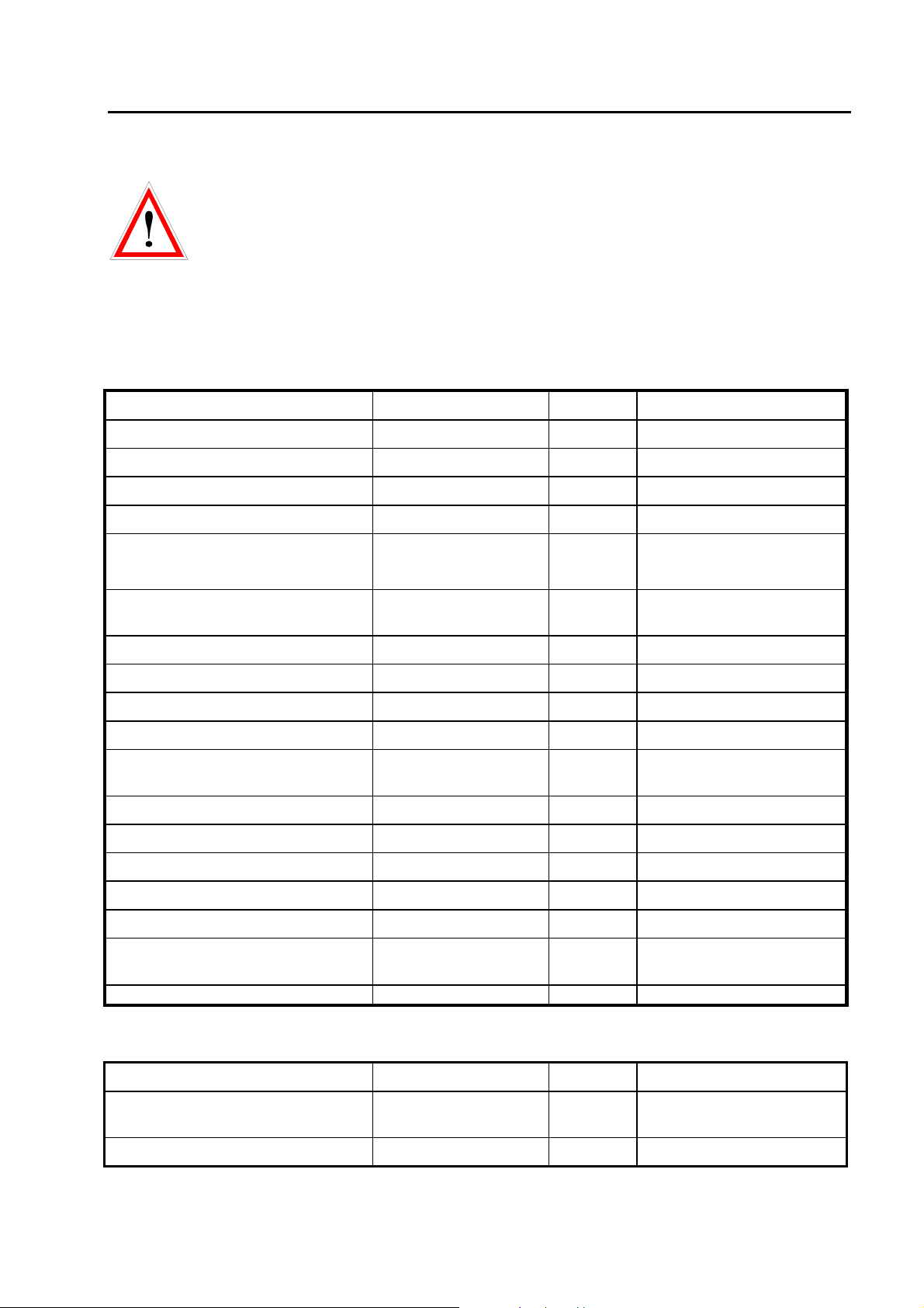
1.3.9 Common mode test with EXT-TRA3000 C
Caution
To avoid any damage of the EUT during CM test set-up the EUT power cord on the rear side of the
TRA3000 shall be removed. When the CM test is selected the power line is disconnected and the PWR1
and PWR2 can not switched “ON”. As soon as an other test e.g. Surge is selected the PWR1 and PWR2
can be activated and the power voltage is on L at the front of the TRA3000.
1.3.9.1 General Generator Specification
Voltage setting range 0.1 to 35V 0.1 V resolution
Source impedance 50 Ohm ± 10%
Synch turn ON/OFF 0° ± 5% of test voltage
Operation mode: Continuous
Leves V 1 up to 4
Open circuit output voltage range Vmin 0.1V
Test frequencies DC, 16,7Hz, 50Hz and
Test durtion 1 up to 30’000s
Test time 1 up to 30’000s
Operation mode: Short
Leves V 1 and 2
Test frequencies DC, 16,7Hz, 50Hz and
Test duration 1 up to 10s
Repetition Duration + 1 s
Test time 1 up to 10s
Operation mode: fix frequencies
Range DC up to 150kHz 1Hz resolution
-10%
Vmax 30V
60Hz
60Hz
+10%
Operation mode: sweep
See chapter below
frequencies
Levels 1 up to 4
1.3.9.2 Characteristics and performance of the generator for d.c. tests
Test levels for continuous operation 1, 3, 10, 30 V
Test levels for short time operation 10, 30 V 1 to 10s Selectable short duration
time
Switching time at d.c. ON/OFF Between 1 - 5 µs 1Hz resolution
25/162
Page 26
TRANSIENT3000
1.3.9.3 Characteristics and performance of the generator for a.c. tests
Test levels for continuous operation 1, 3, 10, 30 V
Test levels for short time operation 10, 30 V 1 to 10s Selectable short duration
time
Test frequencies 16,7Hz, 50Hz and
60Hz
1.3.9.4 Characteristics and performance of the generator for tests in the frequency range 15 Hz150 kHz
Frequency range 15Hz up to
150kHz
Test levels 1, 2, 3, 4,
Decade time 10s up to 1000s
Step Sizes of the preceding
frequency value
Voltage changes 20dB / decade.
No test level is defined below 15Hz, excluding d.c.
Generator output is short circuit protected
For further information about short duration disturbance test see EXT-TRA3000 C-SHORT instruction
sheet.
2 to 10%
20dB / decade.
-10%,
+10%
Decreases
Increases
15 up to 150Hz
1.5kHz up to 15kHz
1.3.10 Power line limits on EUT power input of TRA3000
Power line voltages greater than 280V and frequencies higher than 70Hz are the limit for the power
dissipation of the SURGE circuit. The TRA3000 measures the voltage and the frequency. When higher
voltages or frequencies are measured the following modes will be activated:
Gating Mode Gating Time Gating activated
0 No Gating F < 70Hz & V < 280Vrms
1 0.5 Seconds F < 70Hz & V >= 280Vrms
2 0.1 Seconds F >= 70Hz
Explanation of the gating mode:
The coupling path between the SURGE circuit and the power line will be opened and only closed during
Surge release.
Possible states during “RUN” modes:
0 Æ 1 0 Æ 2 1 Æ 2
1.3.11 Synchronisation of TRA3000 to mains frequencies Synchronisation to EUT power input
A minimum voltage of 30V rms must be applied to the power input on the rear of the TRA3000 (PWR1 or
PWR2) to synchronize the Surge to the mains. The LED within the connector on the front panel indicates a
proper synchronisation.
26/162
Page 27
TRANSIENT3000
Synchronisation to Impulse Out
Generally we recommend the synchronisation to the TRA3000 (PWR1 or PWR2). The voltage at the PWR
inputs is limited to 280Vrms.
That the synchronisation via the Impulse Output (Synchro on Output) works correct, the following condition
must be fulfilled:
If frequency <= 100Hz, than the voltage must be > 100Vrms
or
If frequency > 100Hz, than the voltage must be > 150Vrms
Caution
When PWR1 is turned OFF also the synchronisation signal is turned OFF. TRA3000 displays the following
message.
Î Generator Malfunction „No synchronisation signal“
1.3.12 Measuring circuit, measuring outputs
Monitor outputs for measuring equipment e. g. oscilloscope:
Outputs Relations Tolerances Maximum values
SURGE Voltage
SURGE Current
EUT Power Voltage
EUT Power Current
Numeric measurements e.g. measuring values in the display and in the report.
Display Range Tolerances
SURGE Voltage Peak value
SURGE Current Peak value
EUT Power Voltage (rms)
EUT Power Current (rms)
10 V equals 4000 V
10 V equals 2000 A
10 V equals 400 V
10 V equals 100 A
0 to 5000 V
0 to 2500 A
0 to 280 V
0 to 18 A
5 %
5 %
3 %
5 %
3 %
3 %
3 %
3 %
4800 V
2400 A
480 V
500 A
27/162
Page 28
TRANSIENT3000
V
gg
gg
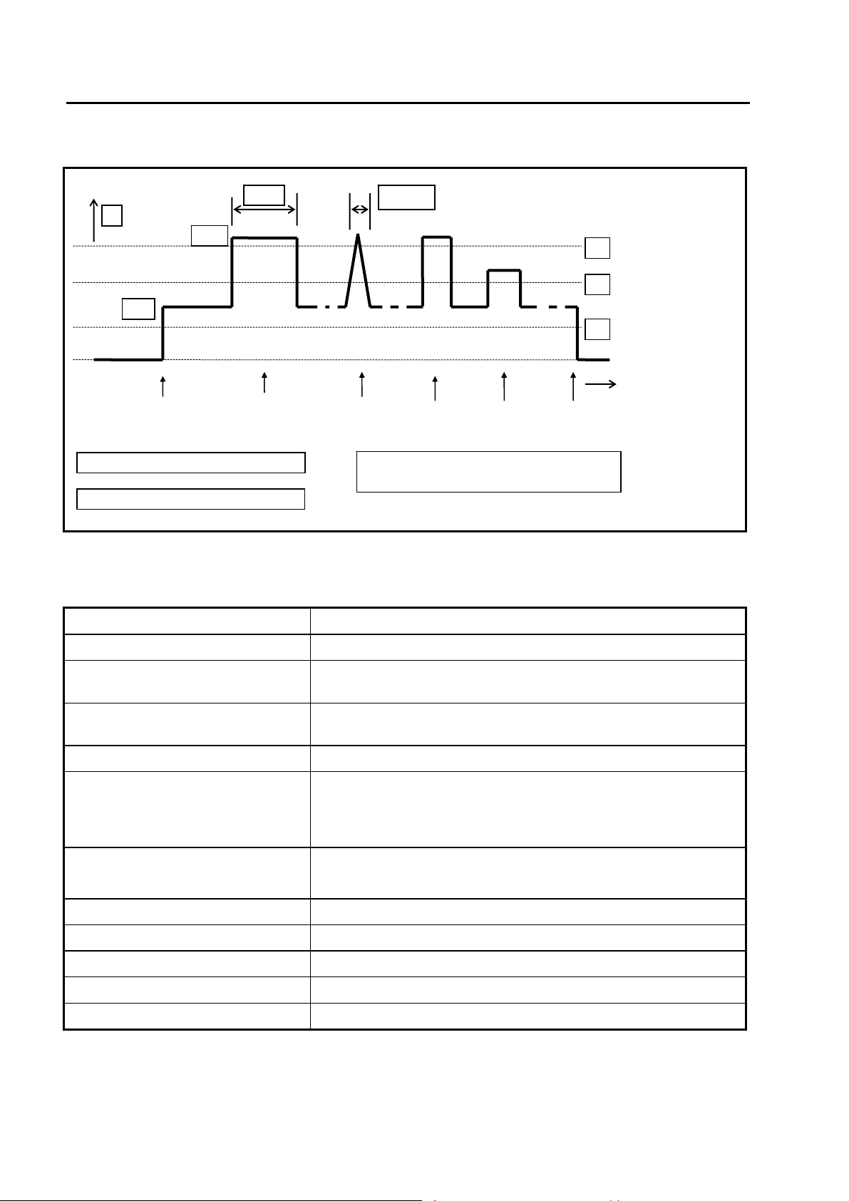
1.3.13 Trigger Output Levels
1 Tri
3 Tri
V
10 V
5
EUT Power
ON
er level 7 V interference
er level 3 V Power ON/OFF
1 ms 150 ns
SURGE
1.3.14 Control
DIPS1 DIPS2
EFT
EUT Power
2 Trigger level 9 V for triggering only
DIP1
2
1
3
t
OFF
Set-up memory Up to 200 test set-ups can be stored
Test sequences the set-ups can be linked serially
Ramps automatic linear variation of one parameter e.g. voltage, frequency
etc.
Synchronisation on different power
line frequencies
Impulse release Manual or automatic
Failure detection on EUT -External Input EUT failed
Safety switching Emergency stop
Control of an external variac separate remote-control output
Failure analysis report, servicing USB port with USB stick. USB stick delivered with TRA3000
Control of external CDN via RS 485 port
Remote control from GENECS Ethernet
Remote control customized program RS232
10 up to 400 Hz
-Manual detection
-Selectable limit value for impulse voltage and current for SURGE
Switch off the EMC Test and the EUT power
28/162
Page 29
TRANSIENT3000
1.4 Mechanical dimensions
Tester -Type Dimensions [mm] Weight [kg] Versions
width x depth x height
TRA3000 F-S-D-V-C and all
Versions
550 x 600 x 190 See standard accessories
list
19" 4 UH
1.5 Power Consumption
The power line input is located on the rear side of the TRA3000 F-S-D-V-C.
Voltage between phase and neutral 100V up to 240V 50 up to 60Hz
Power consumption Standby: power cord connected, switch
turned “OFF”
Power “ON” no EMC test running
Power “ON” EMC test running
Power cords see next paragraph „Accessories delivered with the TRA3000
< 1W
75W
<150VA
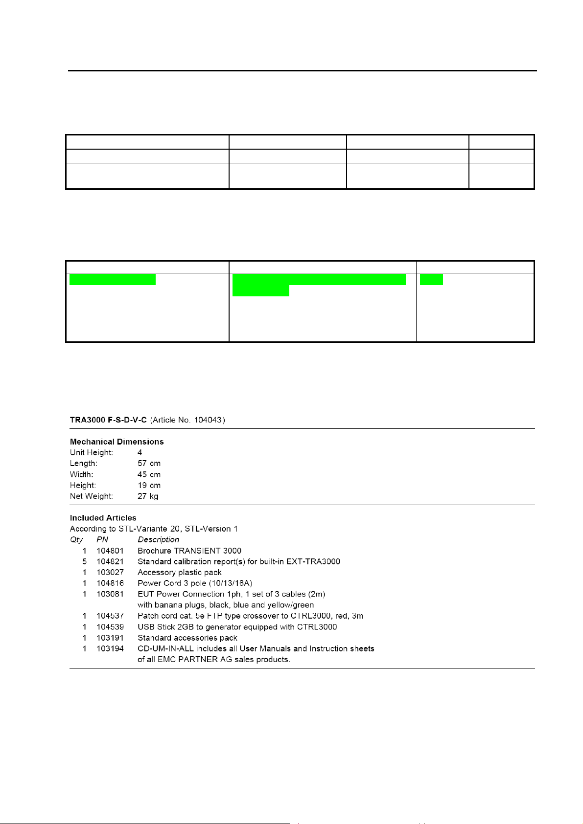
1.6 Included articles, dimensions
29/162
Page 30
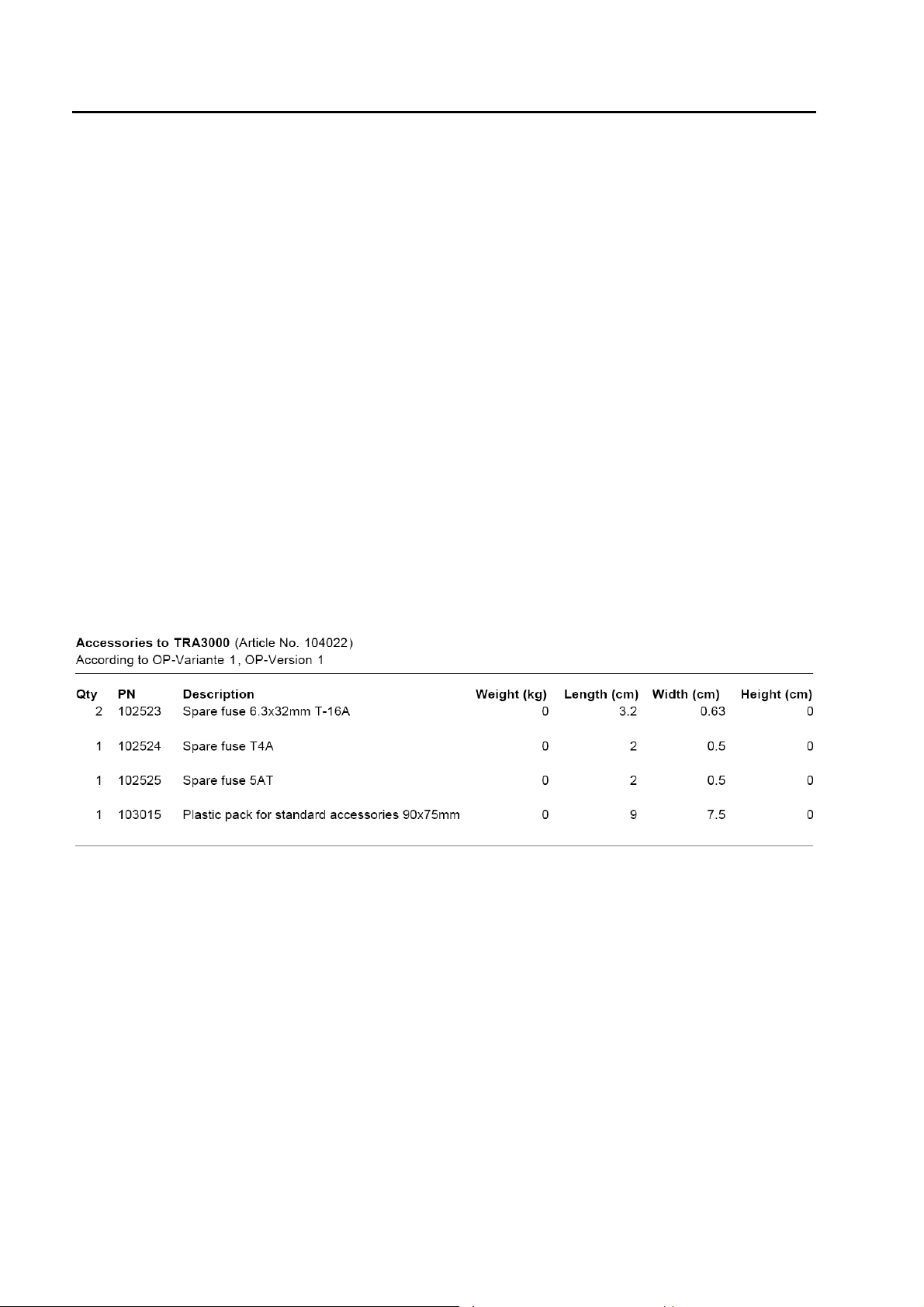
TRANSIENT3000
Dimensions of TRA3000 Versions
Article-No. Type Height Units Length (cm) Width (cm) Height (cm) Net Weight (kg)
104029 TRA3000 F 4 57 45 19 18
104030 TRA3000 S 4 57 45 19 19
104031 TRA3000 D 4 57 45 19 23
104032 TRA3000 C 4 57 45 19 17
104033 TRA3000 F-S 4 57 45 19 20
104034 TRA3000 D-V 4 57 45 19 23
104035 TRA3000 F-V 4 57 45 19 24
104036 TRA3000 S-V 4 57 45 19 25
104037 TRA3000 F-D-V 4 57 45 19 25
104038 TRA3000 S-D-V 4 57 45 19 26
104039 TRA3000 D-V-C 4 57 45 19 25
104040 TRA3000 F-S-C 4 57 45 19 21
104041 TRA3000 F-S-D-V 4 57 45 19 27
104042 TRA3000 S-D-V-C 4 57 45 19 0
104043 TRA3000 F-S-D-V-C 4 57 45 19 27
104669 TRA3000 F-C 4 57 45 19 19
104869 TRA3000 F-S-D 4 57 45 19 21
104989 TRA3000 S-C 4 57 45 19 19
1.7 Standard accessories
30/162
Page 31

2 Safety
The TRA3000 F-S-D-V-C belongs to Safety class 1
2.1 Safety standard
The TRA3000 F-S-D-V-C fulfils the requirements of the safety standards IEC 61010 for laboratory
measurements equipment „Safety requirements for electrical measuring, control and laboratory equipment“.
Based on EN 61010 the declaration of conformity to low voltage directive (LVD 73/23/EEC O.J.N° L77,
1973-03-26) is given.
This manual is an integral part of the TRA3000 F-S-D-V-C tester. The instructions contained in the
manual regarding operation and the test set up are to be strictly observed.
2.2 Climatic Conditions
The TRA3000 F-S-D-V-C contains high voltage circuits in integrated form. EMC PARTNER only
guarantees a correct functioning of the tester TRA3000 F-S-D-V-C and the associated accessories, if the
TRA3000 F-S-D-V-C is operated in the climatic conditions specified.
Temperature 15 °C to 35 °C
Relative humidity 45 % to 75 %
Atmospheric pressure 86 kPa to 106 kPa (860 to 1060 mbar)
Not influenced by: direct solar radiation, rain or condensation water, dust or larger
electro magnetic fields as specified in the EMC compatibility chapter.
The TRA3000 F-S-D-V-C should be operated in a dry, clean room. If for any reason condensation water is
present in the TRA3000 F-S-D-V-C, then no TRA3000 operation should be started before the tester is
thoroughly dry.
It is strictly forbidden to operate the TRA3000 F-S-D-V-C in rooms with a gas explosion risk. The
high voltage of the TRA3000 F-S-D-V-C can generate sparks, which could ignite the gas.
People with heart pacemakers should not be in the vicinity of the test set up during operation.
E-TRA3000 F-S-D-V-C_E-Manual 31/162
Page 32

TRANSIENT3000
2.3 Precautionary measure during use
The TRA3000 F-S-D-V-C generates high voltages. The energy content of the SURGE impulse is high and
can be dangerous with improper use. It is wise to observe the following rules:
• Never touch the EUT when a test is in operation.
• Touch no connectors of interconnection cable when a EMC test is in operation.
• The high voltage of the TRA3000 F-S-D-V-C and the power on the EUT must be turned off before a
manipulation on the EUT is carried out.
• For all services, e.g. check of the fuses, the power cord must first be unplugged.
The TRA3000 F-S-D-V-C must be connected to power line with a safety ground. If an isolation transformer
is involved in TRANSIENT supply the secondary side of the isolating transformer must be grounded.
2.4 Electromagnetic Compatibility
The outputs of the TRA3000 F-S-D-V-C and the links between TRA3000 F-S-D-V-C and the EUT can emit
disturbances. Please consider the national PTT rules.
The Test System TRA3000 F-S-D-V-C should not be operated near sensitive measuring and control
systems.
The TRA3000 F-S-D-V-C fulfils the following immunity requirements:
• Electrostatic discharge
• Burst EFT
• SURGE
Level 4 (8 kV) (IEC 61000-4-2)
Level 4 (4 kV) (IEC 61000-4-4)
Level 3 (2 kV) (IEC 61000-4-5)
2.5 The manual is an integral part of the equipment. Refer to the manual.
This manual is an integral part of the TRA3000 F-S-D-V-C. The safety rules and precautions in the
manual must be observed. EMC PARTNER and their representatives are not responsible for damage
to persons and equipment by not observance of safety rules and precautions in the manual.
32/162
Page 33

TRANSIENT3000
2.6 Sécurité
L’appareil de test TRA3000 F-S-D-V-C est un équipement de la classe de sécurité 1
2.6.1 Normes de sécurité
L’appareil de test répond aux exigences des normes de sécurité CEI 61010 (Règles de sécurité pour
appareils électriques de mesurage, de régulation et de laboratoire) et à la norme de sécurité VDE 0104
(Circuits de sécurité, lampes d’avertissement ou connecteurs pour les lampes d'avertissement).
Le produit satisfait aux exigences de la directive basse tension LVD 73/23/CEE (JO n ° L77, 1973-03-26).
L’observation de cette directive a été contrôlée selon DIN EN 61010 (correspond à CEI 61010).
Ce manuel est une partie intégrante de l’appareil de test TRA3000 F-S-D-V-C. Les instructions contenues
dans le manuel en ce qui concerne le fonctionnement et l'installation d'essai, doivent être strictement
respectées.
2.6.2 Conditions climatiques
L’appareil de test contient des circuits haute tension sous forme intégrée. EMC PARTNER ne garantit le
bon fonctionnement de l’appareil et des ses accessoires, que s'il est utilisé dans les conditions climatiques
spécifiées ci-dessous.
Température 15 ° C à 35 ° C 60 à 90 ° F
Humidité relative 45% à 75% 12,9 à 15,4 psi
Pression atmosphérique 86 kPa à 106 kPa (860 à 1060 mbar)
Ne pas exposer à: rayonnement solaire direct, pluie ou eau de condensation,
poussière ou un niveau plus important de champ électromagnétique
que spécifié dans le chapitre sur la compatibilité électromagnétique.
L’appareil devrait être utilisé dans un endroit propre et sec. Si pour une raison quelconque de l'eau se
condense dans l’appareil, aucun test ne devra être effectué avant que l’appareil soit sec.
Il est strictement interdit de faire fonctionner l’appareil dans des endroits contenant des gaz avec
risque d'explosion. La haute tension de l’appareil peut générer des étincelles qui pourraient
enflammer le gaz.
Les personnes portant un stimulateur cardiaque ne doivent pas être à proximité de l'installation d'essai en
cours d'opération
33/162
Page 34

TRANSIENT3000
2.6.3 Mesures de précaution lors de l'utilisation
L’appareil de test TRA3000 F-S-D-V-C est une source de puissance. L’énergie à la sortie de celle-ci est
élevée et peut être dangereuse si elle n’est pas utilisée correctement. Il est conseillé d'observer les règles
suivantes:
• Ne jamais toucher le EST (équipement sous test) quand un test est en fonctionnement
• Ne jamais toucher les connecteurs ou les câbles quand un test CEM est en marche.
• Avant toute manipulation de l’EST, s’assurer que l’appareil de test est désactivée et que l’EST est
déclenché.
• En cas de service, comme vérifier les fusibles, le cordon d'alimentation doit être débranché.
L’appareil de test TRA3000 F-S-D-V-C doit être connecté à une ligne électrique avec liaison à la terre. Si
un transformateur d'isolement est utilisé, le côté secondaire doit être mis à la terre.
2.6.4 Compatibilité électromagnétique
Les sorties de l’appareil de test TRA3000 F-S-D-V-C et les câbles de connexion du système à l'EST
peuvent émettre des perturbations. Veuillez s’il vous plaît examiner les règlements nationaux applicables à
l'environnement local.
L’appareil de test TRA3000 F-S-D-V-C ne devrait pas être utilisé à proximité de systèmes de mesure et de
contrôle sensibles.
L’appareil satisfait aux exigences d'immunité suivantes:
• décharges électrostatique
• Burst EFT
• SURGE
niveau 4 (8 kV) (IEC 61000-4-2)
niveau 4 (4 kV) (IEC 61000-4-4 Ed.2)
niveau 3 (2 kV) (IEC 61000-4-5 Ed.2)
Reportez-vous au manuel
2.6.5 Le manuel fait partie intégrante de l'équipement.
.
Ce manuel fait partie intégrante du TRA3000 F-S-D-V-C. Les règles de sécurité et les précautions à
prendre dans le manuel doivent être respectées. EMC PARTNER et ses représentants ne sont pas
responsables des dommages causés aux personnes et au matériel découlant du non respect des règles de
sécurité et des précautions à prendre citées dans le manuel.
34/162
Page 35

TRANSIENT3000
2.7 Sicherheit
TRA3000 F-S-D-V-C entspricht der Schutzklasse I. TRA3000 F-S-D-V-C darf nur mit einem
Versorgungskabel mit enthaltenem Schutzleiter betrieben werden.
2.7.1 Sicherheit Standard
TRA3000 F-S-D-V-C erfüllt alle Anforderungen nach Sicherheit Standard IEC61010 "„Safety requirements
for electrical equipment for measurement, control and laboratory use. Basierend auf EN 61010 (IEC 61010)
ist die Deklaration zur Einhaltung der Niederspannungsrichtlinie LVD 73/23/EEC (O.J. N° L77, 1973-03-26)
gegeben.
Dieses Manual ist Bestandteil des TRA3000 F-S-D-V-C Generators. Alle im Manual befindlichen
Hinweise und Anweisungen sowie Testkonfigurationen sind strikte einzuhalten.
2.7.2 Klimatische Bedingungen
Die unten aufgeführten klimatischen Bedingungen müssen für einen einwandfreien Betrieb eingehalten
werden.
Temperatur 15 °C bis 35 °C 60 bis 90°F
Relative Luftfeutigkeit 45 % bis 75 % 12.9 bis 15.4 PSI
Atmosphärischer Druck 86 kPa bis 106 kPa (860 bis 1060 mbar)
Keine Einwirkung von: Bei direkter Sonneneinstrahlung, Regen, Staub, starken
elektromagnetischen Felder als spezifiziert unter “Elektromagnetische
Verträglichkeit“
TRA3000 F-S-D-V-C darf nur in trockener und sauberer Umgebung betrieben werden. Ist aus
irgendwelchen Gründen Kondenswasser im TRA3000 F-S-D-V-C zu erkennen, muss TRA3000 F-S-D-V-C
vor Inbetriebnahme vollständig austrocknen.
> TRA3000 F-S-D-V-C darf nicht in explosionsgefährdeten Zonen betrieben werden.
> Personen mit Herzschrittmacher sollten sich während dem Betrieb nicht in unmittelbarer Nähe
aufhalten.
35/162
Page 36

TRANSIENT3000
2.7.3 Vorsichtsmassnahmen während dem Betrieb
TRA3000 F-S-D-V-C kann Hochspannung an den Anschlüssen führen. Bei unsachgemässer Bedienung
entstehen grosse Gefahrenquellen. Folgende Regeln müssen beachtet und eingehalten werden.
Nie während einem Test den Prüfling (EUT) berühren
Nie Steckverbindungen oder Kabel berühren wenn ein EMC Test abläuft.
Vor dem Berühren des Prüflings sicherstellen, dass dieser Spannungslos ist. Entladezeiten interner
Speicherladungen beachten.
Für alle Servicearbeiten (Sicherungswechsel) muss das Versorgungskabel (MAINS SUPPLY) aus
gesteckt werden.
Der TRA3000 F-S-D-V-C darf nur an ein Speisenetz mit Nulleiter und Schutzerde angeschlossen werden.
Wenn ein Isolationstransformator verwendet wird muss die Sekundärseite mit der Schutzerde verbunden
werden.
2.7.4 Elektromagnetische Verträglichkeit
Der Power Output von TRA3000 F-S-D-V-C und die Anschlusskabel zum Prüfling können Störfelder
abstrahlen. Die örtlichen Bestimmungen müssen berücksichtigt werden.
TRA3000 F-S-D-V-C nicht in unmittelbarer Nähe von empfindlichen Messgeräten betrieben. Die
Messergebnisse könnten beeinflusst werden.
TRA3000 F-S-D-V-C erfüllt die folgenden Störfestigkeiten:
Elektrostatische Entladung Level 3 (6kV / 8kV) (IEC 61000-4-2)
Burst EFT Level 3 (2kV) (IEC 61000-4-4)
SURGE Level 2 (1kV) (IEC 61000-4-5)
Beachten Sie alle Angaben in der Bedienungsanleitung
2.7.5 Dieses Manual ist Bestandteil von TRA3000 F-S-D-V-C und dessen Testumgebung.
Die enthaltenen Sicherheitsbestimmungen und Vorsichtsmassnahmen müssen eingehalten werden.
Bei deren Nichteinhaltung übernimmt EMC PARTNER und deren Vertreter bei Schaden an Personen
oder Messeinrichtungen keine Verantwortung.
36/162
Page 37

3 Mechanical structure
3.1 General
The TRA3000 F-S-D-V-C is ideal for running tests in development/test laboratory environments and for
outdoor service on larger systems. For outdoor service, the TRA3000 F-S-D-V-C can be fitted into a military
case.
For better understanding, the TRA3000 F-S-D-V-C will be divided into two parts:
• The left hand part of the TRA3000 F-S-D-V-C contain the control and measurements. The left hand side
of the front panel, is called the control panel.
• The right hand part contains all high voltage circuits, such us high voltage source, high voltage switches,
the impulse-forming network and the coupling / de-coupling network. This part is called the operation
panel.
Fig.3.1
The power connections of the TRA3000 F-S-D-V-C and the EUT are located on the rear panel. With the
EUT power inputs on the rear side and the outputs on the front side an optimum de-coupling is guaranteed.
This arrangement allows test set-up without parallel-running cables.
The TRA3000 F-S-D-V-C is available with different options:
Standard with handles on both side as showed in Figure 3.1. This version is recommended for use in
development and EMC test laboratories.
19“ insert version. The handles are removed and angle brackets are fixed on both sides for fitting the
TRA3000 F-S-D-V-C in a 19“ rack. When the TRA3000 is equipped with an EFT circuit the EFT output
must be maximum 50 cm above the reference ground plane.
Standard with handle in a military case
. This version is recommended for outdoor EMC testing.
E-TRA3000 F-S-D-V-C_E-Manual 37/162
Page 38

TRANSIENT3000
3.2 Impulse-forming Networks
Behind the operation panel, the high voltage source, the polarity change-over switch, the impulse
capacitors, the semiconductor switch and the impulse forming networks are located.
The impulse capacitor Cs is charged by the high voltage source. The discharge of the high voltage
capacitor is done via the semiconductor switches. The impulses are formed by the different impulse forming
networks.
38/162
Page 39

TRANSIENT3000
3.3 Measuring Circuit
The SURGE impulse voltage is measured differentially with two internally-located voltage dividers. The
current is measured with a current monitor with differential amplifier. The peak values of voltage and
current are memorised and shown in the display. With the two CRO outputs, the voltage and current
waveform can be monitored on a oscilloscope.
fig. 3.2
SURGE high
SURGE low
10 V corresponds
to. 4000 V
10 V corresponds
to. 2000 A
3.4 Coupling / De-coupling Network CDN
The coupling / de-coupling network (CDN) of the TRA3000 F-S-D-V-C allows the superimposition of the
EFT or SURGE impulses onto the power line of the EUT. Switching of the different coupling paths can be
programmed. For the voltage DIPS test, the de-coupling network is automatically by-passed.
SURGE EFT
9 µ or 18µ
bypass
bypass
fig. 3.3
0 Ω or 10 Ω
33 nF
L
PE
N
3.5 EUT power supply at DIPS
In the operation mode (DIPS voltage interruption), the switch S1 turns on the EUT Power 1 power source
( undisturbed level). S2 turns on the power to EUT Power 2 (disturbed level). The internal variac can be
replaced by an external variac or PS3 power supply and therefore the EUT Power 2 can be generated by
internal or external means.
For DIP testing, the NEUTRAL must be close to earth potential (PE). If voltage is present on the
Neutral an error will be shown on the TRA3000 F-S-D-V-C display. If the Neutral is not close to
earth potential, an isolation transformer must be used between the mains supply and TRA3000
F-S-D-V-C input..
39/162
Page 40

TRANSIENT3000
Phase
EUT Power 1
S2
EUT Power 2
Neutral
External or internal Variac (or
PS3)
fig. 3.4
EUT Power 1
S2
EUT Power 2
U - Power line
S1= OFF
S1= ON
S2 = OFF
Fig. 3.4
At DIPS to 0 % of the power line voltage, two operating conditions can be differentiated:
A) Switch S1 is opened, the voltage of the power decreases at the EUT with the discharge constant of the
EUT (High Z at 0% = ON)
B) Some µs after switch S1 has opened, switch S2 will be closed and the EUT will be discharged via the
circuit EUT Power 2 (High Z at 0% = OFF).
AT High - Z Mode = OFF and large capacitive loads, the large capacitance will be discharged via the
internal variac at the beginning of the interruption. A large current will result, if an interruption to 0% of the
power line voltage is generated. To avoid reducing the life span of the carbon contact electrode of the
variac, it is recommended to make a short circuit with an external bridge between L2 and N of EUT Power
2.
Vrms between EUT Power 1 and EUT Power 2 must be lower than 250V. Use for EUT Power 1
and 2 equal phase L.
The maximum voltage on the inputs of EUT power 1 or EUT power 2 must be lower than 280V.
High voltage s will destroy the varistors on the inputs.
S2= ON
S1= ON
S2= OFF
L
U-power
N
L
U-power
N
EUT
EUT Power
Output
40/162
Page 41

4 Control Panel
4.1 Front panel of the TRA3000 F-S-D-V-C
2
1
3
4
fig.4.1
The most important elements of the front panel are:
1. Control panel
2. Operation panel
3. Handles or angle bracket for the 19“ rack
4. Large surface earth connection
The controls on the front and rear panels are protected by the angle bracket (3).
For indications, the follow colours are generally used:
green
read
yellow
4.1.1 Control part
Power on
EMC Tests active
General signals
Control of the TRA3000 F-S-D-V-C is carried out by internal computer. The computer controls the EMC
tests, stores the inputs of the numeric input terminal, updates the display, checks whether the inputs of the
operators are valid values or not, stores the program and prepares test reports. The operator
communicates with the TRA3000 F-S-D-V-C via the numeric input terminal, the display and the soft keys.
For better understanding, the control panel elements will be explained separately from the connection
panel.
E-TRA3000 F-S-D-V-C_E-Manual 41/162
Page 42

TRANSIENT3000
1
2
17
9
10
7
11
5
12
15
8
13
6
4
18
14
fig. 4.1.1
4.1.1.1 The Display (1)
All important information for the operator is permanently shown on the display during EMC testing. The
large graphic display includes additionally 6 soft-keys and some hints or setting range information.
4.1.1.2 Soft-keys (2)
The program in the TRA3000 F-S-D-V-C is very complex, therefore six soft-keys are provided in order to be
able to move and quickly change to different menus.
Example of "Main"
Test Main Ramp Menu
Choice of tests
EFT
ESD
SURGE
DIP (Interruption)
VAR. (Variation)
MF (Magnetic field)
CM (Common Mode)
-pre-setting of
nominal values
-pre-set of
coupling path
e.g. EFT
EFT V-peak.
Polarity
Repetition Burst
Spike frequency
HV-Out
-definition of
different ramps
e.g. EFT
EFT V-peak
Synchronisation
Burst duration
Spike Frequency
-Power
-EUT action if failed
e.g.
Power "ON /OFF" in °
Current limits
Synchronisation
Variac setting
4.1.1.3 Push button ON/STBY (6)
With this button, the TRA3000 F-S-D-V-C will be set into the power ON / OFF mode. In the turn off mode,
the control and the signals are deactivated. In this status of the TRA3000 F-S-D-V-C, the power
consumption is at a minimum of 5 W.
4.1.1.4 Push button up and down (7,8)
These two buttons make it possible to moves the cursor forwards or backwards through the menus.
42/162
Page 43

TRANSIENT3000
4.1.1.5 Measuring outputs EUT Power Voltage (9) and Current (10)
A signal corresponding to the mains voltage is available at these two BNC outputs „EUT power“. Maximum
12 V for the voltage at the output (9) and maximum 12 V for the current at the output (10).
4.1.1.6 Measuring outputs SURGE Voltage (11) and Current (12)
During SURGE tests, voltage sequence of the SURGE waveform can be measured at the output socket
(11) and the current sequence at output socket (12). The range and the accuracy of the measuring system
is given in the Chapter 1.2 Technical data Section 1.2.8 measuring circuits, measuring outputs.
4.1.1.7 Trigger output for oscilloscope (13)
This output provides all the necessary trigger impulses for the different tests. The different trigger levels
and the time delays are listed in Chapter 1.2 Technical data paragraph 1.3.13
4.1.1.8 The Push-button ENTER (14)
Numeric values are changed only when the ENTER button is pressed.
4.1.1.9 Push-button Edit (15)
This button has a multifunctional use:
• Activate the dialogue line
• Open pull down windows
4.1.1.10 Buttons F1 to F6 (17)
The buttons F1 to F6 are allocated to the function as indicated on the display. Depending on the menu,
different functions are allocated to the six buttons.
4.1.1.11 Numeric control panel (18)
If the cursor is activated in one line of the display, then data can be input with the numeric key board. Each
data input must be terminated with ENTER.
The button BSP (Backspace) enables correction of an incorrect data input.
4.1.1.12 Dialogue line within the display (5)
Indicates what range can be selected or which next step must be done.
4.1.1.13 USB button (5)
All service date is stored to the USB stick when inserted into the rear panel “USB Port”
43/162
Page 44

TRANSIENT3000
4.1.2 Operation panel
19 20 21
23
24
25
36
22
27
29
35
32
26
30
31
33 34
Fig. 4.1.2
4.1.2.1 Button Run (19)
With the „Run“ button, a test can be started or interrupted.
4.1.2.2 Manual Trigger (21)
When manual trigger is programmed and the tester is ready for manual trigger, this will be indicated by the
LED. As soon as the signal occurs the pulse can be released by pressing the manual trigger button.
4.1.2.3 Signalling the EMC test type(26)
The LED (26) signals which of the seven possible EMC test is chosen: ESD, EFT, SURGE, DIPS,
Variation, Magnetic field, Common Mode. A continuous signal indicates which test has been selected in
set-up, while a blinking signal indicates that the test is running.
4.1.2.4 Indication of the coupling path (22)
The four LEDs indicate which path is receiving the disturbance . The three lines of the EUT power, or the
direct high voltage outputs. The signals appear as soon as a test is active. With the buttons above the LED
indicators, coupling path can be changed also during operation.
4.1.2.5 Single phase power output power plug Schuko(23) or banana plug (33) type.
When superposing the disturbance onto the EUT power line, the power cord of the EUT must be connected
with the Socket (23). EMC PARTNER offers adapters for the different types of power cord connectors for
different countries.
44/162
Page 45

TRANSIENT3000
4.1.2.6 Button Power LINE PWR1 (24)
With this button the EUT power is turned on or off at the phase angle defined.
4.1.2.7 Button Variac (25)
With this button the EUT power is turned on from the varic. When the power of the EUT is feed from input
(48) (see Figure 4.2 ) e.g. internal or external variac, this status will be indicated by the LED (25) .
4.1.2.8 Synchro ON EUT Power (36)
When a voltage higher than 30 V is applied at the EUT power 1 input on the rear side of the TRA3000 F-SD-V-C, the synchronisation will be referred to the supply voltage. The LED (36) indicates whether the
synchronisation is based on the EUT power voltage or not. At voltages lower than 30 V the synchronisation
is based on the power line of the TRA3000 F-S-D-V-C (41). If the phase and the neutral are interchanged,
no indication will occur.
4.1.2.9 High voltage pulse output EFT (27)
This output is needed to run EMC tests with the external capacitive coupling clamp or an additional
coupling/de-coupling network.
4.1.2.10 Control plugs EXT-TRA3000 E (29)
This connector is for connecting the ESD discharge circuit accessory EXT-TRA3000 E. See TRA3000 F-SD-V-C accessories.
4.1.2.11 Impulse output SURGE (30,31)
These two connectors are for connecting the SURGE coupling kit accessory or three phase coupling/decoupling networks. See TRA3000 F-S-D-V-C accessories.
The outputs are marked with „high“ and „low“. The „low“ output is not earthed, and a maximum external
voltage of 280 V ac can be connected, as described on the front panel.
4.1.2.12 High voltage (35)
Attention high voltage at the EFT BNC plug) and SURGE ( MC plugs)
4.1.2.13 Earth connection (34)
Particularly for interference tests with high frequency components, such as EFT, a large surface earth
connection is necessary. The earth terminal of the TRA3000 F-S-D-V-C allows a low inductance earth
connection between test equipment and the reference ground plane to be made.
4.1.2.14 Attention, refer to manual (32)
This sign tells the operator to study the manual in detail. Only trained personnel are allowed to operate the
TRA3000 F-S-D-V-C.
45/162
Page 46

TRANSIENT3000
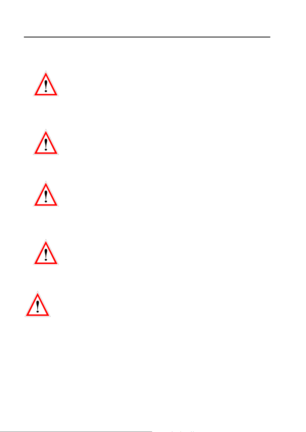
4.2 Rear Panel of the TRA3000 F-S-D-V-C
40
41
42
4.2.1.1 Warnings (40)
High leakage currents. To avoid electric shock the power cord protective grounding conductor must be
connected to ground.
For continued fire protection, replace fuse only with fuse of the specified type and rating. Refer servicing to
qualified personnel. Disconnect power cord before replacing fuse.
Dangerous high-voltage inside. If there is any need to open the instrument, disconnect power cord and wait
at least one minute for full capacitor discharge before opening.
This instrument may be protected by one or more patents or patent applications. Information available upon
request.
4.2.1.2 Power supply of the TRA3000 F-S-D-V-C (41)
The TRA3000 F-S-D-V-C receives its power via power connection (41). A power switch, a fuse and a filter
are built in directly at the mains plug.
Power consumption: turned on minimum < 75VA; maximum power consumption < 150 W, standby < 1 W
The fuse is rated with T 4A / 250 V.
4.2.1.3 Type plate (42)
All important supply information is written on the type plate. Please quote the serial number and type of the
equipment when requesting service or repair.
Typeplate
4.2.1.4 CE mark ( 43)
The CE -mark is needed for the free movement of the goods into and within the European community.
43
44
56
45
45 48
46
53 55
60
54
49
50
51
57
58
59
Fig. 4.2
46/162
Page 47

TRANSIENT3000
p
4.2.1.5 External Variac Control, external synchsonisation (44)
Via this special interface, the external variac can be controlled by the TRA3000 F-S-D-V-C. The external
variac is needed for EUT (>12 A) and mains voltage variation (>5A).
External synchronsation
TRA3000 Basis
10R
27V
External VARIAC
Control
9
ol DSub male
Pin 8
Pin 1
Upin8: 5Vdc…. 24Vdc
Delay max 1us
t = 5….100us
5Hz < f <= 400Hz
(2.5ms ….. 200ms)
4.2.1.6 Attention, refer to manual (45)
This expression requests the operator to consult the manual in detail. Only trained personnel are allowed to
operate the TRA3000 F-S-D-V-C.
4.2.1.7 EUT Power 1; Inputs (46,53)
All input plugs and fuses for EUT power 1 are located in row (46). The two 16 A fuses for phase and neutral
located above. Below the fuses are the three power line connections for the EUT power supply (53). For
the phase, two plugs are available for connecting the internal variac to the power. For external variac
operation, the bridge (53) and (54) must be removed, see Chapter 6 „Testing with the TRA3000 F-S-D-VC“.
Supply data: min. 20 to max. 250 V a.c 16A
Supply data: min. 20 to max. 110 V d.c 10A. Only applicable for TRA versions witouth TRA3000 ..D-V
included. When the TRA2000 ….D-V is included see 4.2.1.9 and 4.1.2.17
Current
[Arms]
16
No a.c. current derating necessary
Time [min]
4.2.1.8 Internal Variac (55)
For the interruption and variation mode tests different voltages are needed. As standard the TRA3000 F-SD-V-C has an internal variac with a continuous current rating of 6 A. At shipment, two bridges are inserted
(53) and (54). The variac is protected with its own fuses. For external variac operation, the two bridges
must be removed, see Chapter 6 „Testing with the TRA3000 F-S-D-V-C“.
47/162
Page 48

TRANSIENT3000
4.2.1.9 EUT Power 2 Inputs (48)
Input for the disturbance level during interruption. When an external source, e.g. external variac or an
external ac/dc source (PS3), is used, the external source must be connected to these inputs (48).
Supply data a.c.: 20 to 250 V 16 A. no derating necessary
Supply date d.c.: 20 to 300 V 10 A. see derating below. Only applicable for TRA versions with TRA3000
..D-V included.
Current
[Arms]
10
8
A temperature sensor protects the high voltage switch in case of d.c. supply.
4.2.1.10 Interface „Port 1“ RS232 for controller PC (49)
The RS232 interface port can be used to control the TRA3000 F-S-D-V-C using an external PC with
customized program. To configure the interface, see Chapter 13 „Remote Control“.
4.2.1.11 Interface „Port 2“ RS 485 for controlling external coupling networks or checking the EUT failed status (50)
Via this interface, the coupling path of external CDNs can be controlled.
For further information, see the specific CDN manual.
4.2.1.12 The USB Port (51)
Via this interface, the service data can be stored on an USB stick. In case of failure the data can be sent via
Email to EMC PARTNER for analysis.
4.2.1.13 Forced cooling of the TRA3000 F-S-D-V-C (56)
A ventilator cools the TRA3000 F-S-D-V-C internally. Forced cooling is necessary for the impulse forming
network devices and the electronic high-voltage switch. A distance of about 20 cm must be maintained
between the rear panel of the TRANSIENT 3000 and any wall, and about 3 cm between the sides of the
TRA3000 F-S-D-V-C and any equipment or wall. The TRA3000 F-S-D-V-C can be built into a 19“ rack, with
3 cm side separation.
4.2.1.14 Ethernet remote control (57)
The Ethernet interface port can be used to control the TRA3000 F-S-D-V-C using an external PC with
GENECS-TRA program. To configure the interface, see Chapter 13 „Remote Control“.
DC AC
5
Time [min]
Current
[Arms]
16
Time [min]
48/162
Page 49

TRANSIENT3000
4.2.1.15 Emergency stop, ( EMERGENCY STOP ) (58)
When the „emergency stop“ input is activated, the EMC test and the EUT power supply will be immediately
interrupted. The power supply of the TRA3000 F-S-D-V-C will not be turned off. The status „emergency
stop“- will be indicated on the front panel. Emergency stop corresponds to 0V at the input.
+24V
10K
CTRL3000
10R
27V
The trigger value at the input is approximately 5Vdc (active low). The
maximum input value is 24Vdc.
Driving with an open-collector output is recommended.
EMERGENCY
STOP
BNC
4.2.1.16 EUT Failed input (59)
This input can be used for a single channel EUT passed/failed detection during the EMC test. EUT failed is
equal to 0V.
+24V
10K
CTRL3000
10R
The trigger value at the input is approximately 5Vdc (active low). The
maximum input value is 24Vdc.
Driving with an open-collector output is recommended.
27V
EUT-FAILED
BNC
49/162
Page 50

TRANSIENT3000
4.2.1.17 EUT Power 1 d.c. input (60)
For d.c. supply of the EUT the inputs (60) must be used. The EUT power 1 d.c. input is not protected by a
fuse. The polarity + and – must be respected. The EUT power switch PWR1 operates only when the
external d.c. supply is correctly connected to + and – inputs.
Supply data: min. 20 to max. 300 V d.c. 10A. Only applicable for TRA versions with TRA3000 ..D-V
included.
Current
[Arms]
10
8
d.c. current derating necessary
Time [min]
5
A temperature sensor protects the high voltage switch in case of d.c. supply.
Further information to d.c. dips and interruption IEC 61000-4-29 can be found in the Instruction sheets of:
104124 EXT-TRA3000 D-29D
104125 EXT-TRA3000 D-29I
50/162
Page 51

5 Preparation for Operation
5.1 Attention, Refer to Manual
This manual is an integral part of the TRA3000 F-S-D-V-C. The safety rules and precautions in the
manual must be observed. EMC PARTNER and their representatives accept no responsibility for
damages to persons and equipment as a results of non-observation of the safety rules and
precautions in this manual.
Before connecting the TRA3000 F-S-D-V-C to a public power line, Chapter 3 „Safety must be carefully
studied.
5.2 Operators and Service Personnel
Only trained personnel should carry out EMC tests. For small groups of maximum 10 persons EMC
PARTNER AG offers the following in-house seminars in English or German:
1. EMV Introduction
2. EMV Standardisation
3. EMC „ESD“ immunity test
4. EMC „EFT“ immunity test
5. EMC „SURGE“ immunity test
6. EMC „DIPS“ immunity test
7. EMC „HARMONICS“ immunity test
8. EMC „MAGNETIC FIELD“ immunity test
9. EMC „CW CURRENT INJECTION“ immunity test
10. EMC „CE-MARK“ transient immunity tests
11. „NEMP“ immunity test
12. „AC, DC, IMPULSE“ insulation test
5.3 Checks before operation
5.3.1 Optical verification of the TRA3000 F-S-D-V-C
Before you unpack the TRA3000 F-S-D-V-C, please check whether the packing is deformed or damaged.
When the TRANSIENT is unpacked, also check whether the tester is damaged. If you detect a damage,
please inform EMC PARTNER and the shipping organisation immediately.
5.3.2 Power source check
On the rear panel, you will find a type plate. Please check whether the Tester has been prepared for the
correct power line voltage of your public power. If the power supply voltage is different please inform EMC
PARTNER AG in Switzerland, or your EMC PARTNER AG representatives.
5.3.3 Connecting the TRA3000 F-S-D-V-C to the power line
Please use the supplied power cord for connecting the TRA3000 F-S-D-V-C to your public power supply.
As stated on the rear panel, the power supply must have an earth safety wire. Please check the earth
connection on your power outlet before you connect and turn on the TRA3000 F-S-D-V-C.
E-TRA3000 F-S-D-V-C_E-Manual 51/162
Page 52

TRANSIENT3000
5.3.4 EUT Power, Power source for the EUT
To connect the EUT Power 1 Input with the public power supply please cut the three black, blue and
green/yellow cables supplied into two halves of the same length. One half used for the EUT Power 1
connection on the rear side of the TRA3000 F-S-D-V-C, and the other half for supplying the EUT from the
front panel. The high inrush current during the DIPS test can only be reached, when the public power
supply can deliver 500 A peak current. The public power supply must be protected by 16 A fuse.
Connection of the internal Variac:
bridge 1
bridge 2
The Bridge 1 connects the internal variac with the public power supply on the primary side.
The Bridge 2 connects the secondary side of the variac to the EUT power 2 input.
Attention: Phase and neutral must be connected correctly. When the phase and the neutral are connected
correctly, this is indicated on the front panel by a green LED.
Public power line
Attention!
If your power supply is equipped with fault current protective switch it may release when
connecting the TRA3000 F-S-D-V-C. A high current will flow to earth when Surges are
superimposed between phase and earth. The impedance of 2 Ohm in series with 10 Ohm and 9 µF
is a load on the power supply.
52/162
Page 53

TRANSIENT3000
Solutions:
1. For testing with TRA3000 F-S-D-V-C use a power supply without a fault current protective switch.
2. Connect an insulation transformer between power supply and TRA3000 F-S-D-V-C. One
secondary output terminal of the transformer must be grounded.
As a results of the leakage current always connect two earth leads to the TRA3000 F-S-D-V-C.
5.3.5 EUT Power, supply of the EUT with voltages differ from the public power line (Variac) Internal Variac
Both bridges must be placed as shown in the
picture . EUT Power 1 must be connected to
the 230 V public power supply.
bridges
Figure 5.3.5.1
Connection external Variac:
The external Variac replaces the internal
Variac.
EUT
Power 1
EUT
Power 2
Figure 5.3.5.2
Remove the two bridges.
EUT Power 1 (L1) of the TRA3000 F-S-D-V-C
must be connected with L1 of the external
Variac.
EUT Power 2 L, N, PE must be connected as
shown on the picture.
In addition connect the control cable between
„External Variac Control“
Accessories delivered with the external Variac
• See VAREXT1000 user manual
53/162
Page 54

TRANSIENT3000
5.4 EUT Power, supply of the EUT with dc
Caution!
bridges
Figure 5.3.6
Preparations:
1. Remove the two bridges on the rear side of the TRA3000 F-S-D-V-C.
2. Connect the DC power supply with EUT - Power 1 d.c inputs. Connect the positive pin of the dc source
with + input and the negative pin with - input.
Before a dc supply for the EUT can be used
the two bridges must be removed.
If the bridges are not removed when the EUT
is powered with dc the internal Variac will be
heated and destroyed.
The TRA3000 can be equipped with different extensions, which results in different operation modes
decribed below:
54/162
Page 55

TRANSIENT3000
5.4.1 TRA3000 not equipped with EXT-TRA3000 D:
No DIP DC (Interrupt) will be visible in the display. The d.c. supply of the EUT can be turned ON/OFF with
the PWR button on the front of the TRA3000. PWR2 is out off order for d.c. supply.
When on + input a negative voltage of the d.c. supply is connected an error message will occur as shown
below.
Without any guarantee from EMCP of correct operation the lower voltage limit of 20V can be extended by
selcting “No” on Power 1 see display below.
5.4.2 TRA3000 equipped with EXT-TRA3000 D
The display indicates the different possibilities of DIPS and Interruptions
5.4.3 DIP DC (Interrupt) without PS3 power supply source of EMC PARTNER
On his own risk the customer can use his own power supply.
In DC Mode only short Int. can be selected. (Volt dips and Volt var. are only selectable when a power
supply PS3 is connected to TRA3000)
Renmark: High-Z at 0% must be selected off
For voltages lower < 20V No in Power 1 and Power2 must be activated. For power >20V Mains must be
selcted.
55/162
Page 56

TRANSIENT3000
5.4.4 Example
(PWR1: 24Vdc PWR2: 6Vdc)
(voltge PWR1 and PWR2 must be selected on
external power supplys)
Remarks:
• The green LED „Synchro on EUT Power“ has no indication.
• The voltage and current measurement EUT Power is inactive. The measurement circuit is designed for
ac only.
SURGE superimposing on dc
For this kind of test the dc voltage must be connected to input d.c EUT-Power 1. The coupling path L to N
must be selected. The coupling impedance is 10 Ω and 9 µF.
This is an advice from EMCP based on experience of customers, where protection devices have been
destroyed when SURGE tests have been carried out with coupling impedance 18 µF and 2 Ohm between L
and N. In the real installation environment they never had a damage of the equal protection devices. In the
IEC 61000-4-5 no specific chapter deals with different d.c. sources. The only hints for Surge tests on d.c.
supply can be found in the single phase test set up examples.
56/162
Page 57

TRANSIENT3000
5.5 Hints for the test set up according to IEC standards
We list below those experiences of EMC PARTNER which are important for the success of the various
tests. This information is only partly given in the standards.
Before a test is started, it is important to define which ports (inputs, outputs) must be tested. For the most
important transient tests the ports are given as follows in the European generic standard:
Enclosure
Ports
Si g na l, D a ta ,
I/O L in e s P o r ts
EUT
AC / DC
Power Ports
Earth Port
figure 5.4
5.5.1 Test set up EFT Ports which must be tested:
AC/DC power supply, signal, data and I/O lines;
Coupling path:
For EFT pulses, the capacitive coupling is the dominant coupling path. The reasons why the capacitance
coupling path play a dominant role are explained in the book „EMV Störfestigkeitsprüfungen“, published by
FranzisVerlag Munich, or in the report „Schmalbandige Störfestigkeitsprüfungen im n-Sekungen Bereich“
by M. Lutz.
An example will show, that the impedance of EFT spikes at a capacitance of 100 pF (e.g. stray capacitance
can be as high as 100 pF) is very low. As an approximation, the rise time of 5 ns can be converted into a
frequency of 100 MHz, and the impedance can be calculated as:
Z=1/ 2π f C = 1/ 6,28 x 100 10
6
x 100 10-9 = 15 mΩ
Test set-up:
As shown in the mathematical example, stray capacitance between coupling plate, tester, cables,
laboratory wall and reference ground plates can have a large influence on the test results. Here are some
hints for the set up of an EFT test:
• The tester must remain on the reference ground plane, and be connected to the reference ground plane
by a low inductive connection.
• On table-top equipment tests, it is not clear from the existing IEC basic documents 61000-4-4 that the
reference ground plane must be on the table, and not on the floor under the table. The EUT must be
lifted 10 cm from the reference ground
• All cables must be placed in a reproducible manner. (We recommend a photo of the test set-up)
Safety:
The burst impulses described in the IEC standard 61000-4-4 are not dangerous to persons, because the
energy and the pulse duration are too low. Testers are available on the market with higher spike
frequencies and longer test duration, where the energy is much higher, and therefore more dangerous to
persons.
As mentioned in Chapter 2, EFT disturbances can affect heart pacemakers or hearing aids.
57/162
Page 58

TRANSIENT3000
5.5.2 ESD test set up Ports w
Enclosure Ports include operational keys, displays, ground and earth points, metallic parts such as
connectors etc.
hich must be tested:
Coupling path:
Basically all types of coupling exist during static discharges. Practical experience shows that, for most
electronic equipment, the current is the dominant parameter.
In practice the path of the discharge current plays an important role e.g. if secondary sparks or breakdown
in the EUT occur the test is no longer reproducible.
The frequencies contained in the ESD discharge current are higher than in the EFT spike impulse. As a
consequences, reproducibility of the ESD test is more difficult than the reproducibility of the EFT test
results. The ESD test is a most complex transient test.
Test set-up:
As shown by the example in the IEC document 61000-4-2 the same test set up can be used for all different
discharge modes (contact-, air- and indirect-discharge). Under the table lays the reference ground plan and
on the horizontal coupling plane is placed on the table.
The test mode used depends on the test object.
The three different kinds of test object are:
Metallic equipment under test
EUT
I
II-<----<----<---- -----<----I I---------> --->---->---->--I
with contact possibility
I
Combination such as metal
case, insulated keyboard
Insulated EUT plastic, paint,
I I I
with discharge
I
----<-----<
voltage test with IEC finger and
varnish
I
Umax
I I I
I I I
I
I
without contact possibility
I
without discharge
( breakdown)
I I I
Discharge directly contacted
with relay tip
direct discharge air discharge indirect discharge
The ESD transient test is a single event test. The susceptibility of an EUT is strongly influenced by the
clock frequency. With the clock frequency, the information will be transmitted in the EUT or to the auxiliary
equipment within a system. The ESD pulse enters the EUT when no information is being transmitted, the
EUT has a very good immunity to EMC test, whereas the equipment will fail in operation. The existing ESD
testers on the market the discharge cannot be synchronised with the clock frequency. Therefore the
number of shots must be increased up to 100 discharges.
Air discharge with IEC finger.
Holding time 5 seconds.
Indirect test with coupling plane
and relay
Safety:
ESD discharges are not dangerous for humans.
58/162
Page 59

TRANSIENT3000
p
protectio
5.5.3 Test set up SURGE
Ports which must be tested:
AC/DC power supply, signal, data and I/O lines; earth connections
Coupling path:
Unlike the EFT and ESD tests stray capacitance are not important here. The frequencies contained in the
SURGE impulses are lower. The galvanic and mutual coupling are dominant. The cable lay-out and the test
set-up is therefore uncritical. The test results are easily reproduced.
Test set-up:
What must be tested?
Protection circuit for inputs, and outputs as shown in the figure below.
Entkopplungsfilter
Back filter
EUT
residual voltage which could
====>
affect the electronic circuitry
coupling
acitance
ca
Surge generator
Voltage
Current
TRANSIENT-3000
primary
protection
secondary
n
figure 5.4.3
Superimposing SURGE pulses onto power lines is carried out using a capacitance between the tester and
the power line. With the SURGE test, the effectiveness of the protection circuit will be tested. The residual
voltage after the protection circuit could affect the electronic parts of the EUT.
The SURGE test is a single discharge, as for ESD. The considerations regarding single discharge which
were made for the ESD discharge also apply here. Synchronisation with the power line frequency is
important, and must be considered.
With the proposed current injection method, the bonding of screen and earth connections can be tested.
Safety:
The SURGE pulses can be dangerous for persons. The EUT and its cables should not be touched during
SURGE EMC tests.
In case of a breakdown in the EUT, it must be remembered that high currents can flow from the power
supply.
59/162
Page 60

TRANSIENT3000
Test set up DIPS, Interruption
Ports which must be tested:
AC / DC power supply
Coupling path:
These disturbances appear on the power lines. Disturbance sources are short circuits between power lines,
power line switching actions and heavy load changes etc.
Legend:
P Power generator
Z(N) Impedance neutral
Z(L) Impedance Phase
L1 Load 1
L2 Load 2
L3 Load 3
F1 Power line fuse
Legende: P Generator, Kraftwerk
Z(N) Impedanz Nulleiter
Z(L) Im pdeanz Phase
L1 G e rä t, L a s t N u m m e r 1
L2 G e rä t, L a s t N u m m e r 2
L3 G e rä t, L a s t N u m m e r 3
F1 Sicherung Phase
F2 Sicherung im Gerät 1
Short circuit at load 1
Kurzschluss in der Last 1
F2 Equipment fuse
figure 5.4.4.1
Test set-up:
• During DIPS test remember that high inrush currents are possible during the turn on phase of the DIPS.
• With switched power supplies the current can increase linearly with the voltage reduction e.g. I= 1A at U
230V, and with reduced voltage of U = 40%, the current increases to 2,5 A.
• For a realistic DIPS and interruption test, the test object must be discharged using the power line
impedance, see Chapter 3.4.
Prüflevel : Spannungsu nterbrüche
Test levels, Voltage interruption
Test Level
% U
T
0 100 0.5*
40 60 25
U
T
70 30
Voltage
Dip/int
% U
T
Duration
(in period)
5
10
50
x
1
Begin of the interruption
60/162
Test Level 70%
Dip 30%
5
10 t period
figure 5.4.4.2
End of the interruption
Page 61

TRANSIENT3000
5.5.4 Test set-up for table top equipment
RP = Reference plane EFT
Test set up Test sequence
Single Phase EUT
HCP = Horizontal coupling plane ESD
1
CNEFT = Coupling clamp for EFT
I. EFT
1. Connect the earth bar of the TRA3000 F-S-D-VC with the flat multiwire cable (1) to the
reference ground plate
2. Put 10 cm insulation between EUT and the
reference ground plate
3. Carry out the tests!
II. ESD
-
RP / HCP
1. Remove the flat multiwire cable (1) between the
earth bar of the TRA3000 F-S-D-V-C and the
reference ground plate
2. Put 0,5 mm insulation between EUT and the
reference ground plate
GRP
GRP = Ground reference plane ESD
3. Carry out the tests!
III. SURGE, DIPS, VARIATION
1. Reinstall the flat multiwire cable 1
2. Carry out the tests!
Three Phase EUT
RP = Reference plane EFT HCP = Horizont al couplinge plane ESD
TRANSIENT2000
CDN-1000
1
EUT
RP / HCP
I. EFT
1. As for single phase EUT
2. As for single phase EUT
3. Connect the Impulse out of the TRANSIENT
with EFT coupling on the threephase
Coupling/De-coupling network CDN-2000-06-32
4. Carry out the tests!
II. ESD
1. As for single phase EUT
2. As for single phase EUT
3. Carry out the tests!
III. SURGE,
1. Make connection 1
2. Connect the surged phase for synchronisation
with EUT Power 1
3. Carry out the tests!
1. Loop the phase for dips and interruption
through the TRA3000 F-S-D-V-C (EUT Power
GRP
GRP = Ground reference plane ESD
2x470k
IV. DIPS Interruption
1)
2. Carry out the tests!
Combination: Immunity and Emission
RP = Reference plane EFT HCP = Horizontal coupling plane ESD
-
-
GRP = Ground reference palne ESD
1
EUT
RP / HCP
GRP
I. TRA3000 F-S-D-V-C Tests:
1. Carry out the tests as explained for single and
three phase EUT
II. HARMONICS-1000-Measurements
1. Harmonics in accordance with IEC 61000-3-2
2. Flicker in accordance with IEC 61000-3-3
3. Immunity Harmonics IEC 61000-4-13
For brochures and further information about
HARMONICS-1000 contact EMC PARTNER AG or
your nearest representative.
61/162
Page 62

TRANSIENT3000
5.6 Practical testing sequence
In practice, the following test procedures has been shown to be reliable:
1. Burst-Testing:
Burst-testing on mains inputs with a test voltage of 4kV
•
Burst-testing of signal and data lines up to 4kV
•
The energy contained in the burst pulses is relatively small, thereby minimising damage to the test object.
The higher the repetition frequency, the more likely that weak points become evident in the test object.
2. ESD-Testing:
With this test, effects induced through the keys and the housing of electronic equipment can be simulated.
Metallic parts, contacted method up to 8 kV
• Insulated parts, air discharge up to 15 kV
In practice, an item that has undergone burst testing shows a better immunity to ESD, than one which has
not. Likewise, an item that has undergone burst testing shows a better immunity to current injection or cw
field tests.
3. Surge-testing:
Surge testing mains up to 2 kV
•
This should be used to test input protection elements and protection circuits installed in electronic
equipment. The energy content is very high in the surge test, and can destroy elements in the EUT.
Surge testing signal and data lines up to 1 kV
•
4. Mains simulation:
As a consequence of the increasing number of non-linear loads, the quality of the mains gets worse and
worse. To be sure that electronic equipment can withstand the mains interference, test are such as:
Mains interruption, Mains under and over voltage variation, harmonics simulation etc. are required.
5. Further testing:
For most EUTs, the described transient tests are sufficient. Further testing of the product to determine
differences, e.g. with regards to the effects of magnetic field on monitors or on protection elements, may be
needed.
Conclusion:
The product determines which kind of EMC test must be applied. It is also important, that EMC testing
should only be carried out by trained personnel, with a knowledge of how the test object should function,
and some knowledge of transients and EMC. The four tests, with their range of impulse types, simulate
only single signals, and do not cover the complete range of EMP phenomena. However, if no more failures
were registered, after a period of EMC testing with electronic equipment and systems in practical operation,
it would not be justified to impose additional EMC tests.
Further EMC test information can be obtained from EMC Partner or from our representatives.
62/162
Page 63

6 Testing with the TRA3000 F-S-D-V-C
6.1 Quick start of the TRA3000 F-S-D-V-C
Only when Chapter 2 „Safety“ and Chapter 5 „Preparation for operation“ and all instructions have been
followed can TRA3000 be operated. A quick start includes the most important tests using the TRA3000 FS-D-V-C.
EMC PARTNER store the needed tests specified in the generic standard "domestic" in the TRANSIENT
3000 before shipping.
To start a set-up, the following steps must be carried out:
• Turn the power switch on the rear side to position I
• Operate the ON/STBY button on the front panel the display turns to:
type of equipment Software version serial number
selectable tests
programmed test 1 to
200
Press "SETUP"
use arrows to move the cursor Page number
programmed tests
back to
selectable test
Quick test example AC EFT +1kV:
• move the cursor with the arrow to number 3
• press F2 Load
loaded test EUT power v, i ++++
Adds a new test Load the
dialogue lines gives hints for the actual display.
Different languages can be chosen.
a programmed
selected test
into the
generator
test can be
deleted
programmed
test can be
linked
selectable tests
main parameter of the
selected test e.g. EFT
programmed tests
programmed
test 1 up to 200.
Go to the next
page
test parameters
back to
programmed
tests
• press "RUN" button
E-TRA3000 F-S-D-V-C_E-Manual 63/162
back to
selectable tests
actual showed
display
ramp selection
v, f, t, °
further settings
like EUT power
voltage, EUT
failed criteria
tests parameters
more test
parameters
Page 64

TRANSIENT3000
test in operation EUT power v, i ++++
test voltage and time
bar. white indicates the
actual test time carried
out
indicates the status of the actual
test.
When in OPTIONS –Preferences- Default Path for Protocol the Web server is selected the protocol will be
shown as an html document.
when the operator detects visual a
EUT failure, F4 can be pressed
and the status of the test turns to
"failed". Protocol shows " test
failed"
by pressing "Mark" the actual test
parameter will be written in the
protocol and showed on the
display at test end.
tests parameters
Well that's easy isn't it ?
All other programmed tests can be started and carried out in the same way. All test can be started or
stopped with the "RUN" button.
The quick-start tests contain only a small part of the testing possibilities of the TRA3000 F-S-D-V-C.
In the next two sections, the additional possibilities of the TRA3000 F-S-D-V-C will be explained in
detail.
64/162
Page 65

TRANSIENT3000
6.1.1 Selection of a language: Deutsch, François, Italian, Espagnol and Beep function
One of the great advantages of the TRA3000 F-S-D-V-C is the language selection. The equipment is
shipped with English language selected. To change the language follow the instructions below.
type of equipment Software version serial number
selectable tests
programmed test setups 1 to 15
Press "Main" - and twice "Menu" - "UTIL" - -EDIT button
display when "Main" has been
pressed
Choose the desired language (e.g. German) with the arrows and quit with the ENTER button and press soft
key F2 "TEST". The display "TEST" has know changed to
type of equipment Software version serial number
dialogue lines gives hints for the actual display
Different languages can be chosen.
display after pressing twice Menu
and UTIL Turn the beep function
"ON" or "OFF" as personally
preferred..
after pressing "EDIT" button
selectable tests
main parameter of the
selected test e.g. EFT
selectable tests
programmed test setups 1 to 15
Further languages are possible on the GENECS software.
Most of the impression and the dialogue line will be
showed in the selected language.
selectable tests
main parameter of the
selected test e.g. EFT
Advantage:
Automatically all expression and remarks on the display and the protocol will be written in german or in the
selected language.
65/162
Page 66

TRANSIENT3000
6.1.2 Protocol possibilities
The TRA3000 F-S-D-V-C can be adapted to printer with serial or Centronics ports. The TRA3000 F-S-D-VC default value are set at shipment: Autoprint ON, Port Centronics, Beep on Trig ON, Beep on Fail ON. The
default values can be changed as follow:
type of equipment Software version serial number
selectable tests
programmed test setups
Press "Main" - and twice "Menu" - "PROT"
display when "Main" has been
pressed
display when "EDIT" has been
pressed
dialogue lines gives hints for the actual display
Different languages can be chosen.
display after pressing twice Menu after pressing "PROT." soft key
Like on mobile phones company
name can be written
selectable tests
On the same way the operator
name can be written
main parameter of the
selected test e.g. EFT
Get protocol data from USB:
Testfile and logo
Two possibility exist to print out the protocol:
USB stick
1. Insert on the rear panel a USB stick.
2. Press the USB button on the front panel
3. Transfer the html document with the USB Stick to a PC
4. Print the protocol from the PC
GENECS Software
Print the html document directly from the PC
66/162
Page 67

TRANSIENT3000
6.1.3 EUT - Power and EUT - Control
For running the interruption, voltage variation and DIPS, the EUT Power 1 Input on the rear side of the
TRA3000 F-S-D-V-C must be connected to the mains. The mains is correctly connected if the green LED in
the symbolic power plug on the front panel of the TRA3000 F-S-D-V-C is glowing. The green indication will
only be visible when the phase and the neutral are connected in the right sequence. If the power main is
connected and the green light is not on, the mains cable phase and neutral must be interchanged. This
ensures that L and N as written on the front panel correspond with the phase and neutral of the mains.
Input power N> 50V and L-N <N Generator malfunction
No synchronisation signal
Message when N and L are
interchanged. Please change L
and N
Different parameter of the EUT power can be selected:
Press "Main" - and once "Menu" - "POWER"
Message when no PWR1 is
connected and SURGE test is
selected
display when "Main" has been
pressed
display after pressing once Menu
and "Power."
Power Main The angle turning "on" the EUT power synchronised to the EUT power
input of the TRA3000 F-S-D-V-C in degrees. With this feature inrush
current of EUT can be checked. The measurement of the current can be
made via EUT-Power I-CRO on the front plate on an oscilloscope.
Power No: This setting must be selected when d.c is applied to the PWR input.
Power PS3: With this setting the PS3 power can be controlled from TRA3000.
The PS3 allows to supply the EUT via the TRA3000 with different power
voltage and frequecies.
display when "PS3" has been
selected
With voltage the power and
Frequency of the PS3 can be
selected.
Display when power2 “Edit” has
been pressed
Variac voltage: When the variac with button PWR2 is activated the output voltage can
be changed directly by editing the output voltage. Online the power
voltage is measured and indicated on top of the display.
Current Lim.: When the EUT supply current will reach the selected limit the test will be
stopped and the EUT power will be turned OFF. The current limiter can
be used for automated test during night etc. The reaction time of the
limiter is several 100 ms. During a variac regulation, or while printing a
report the current limiter is inactive.
67/162
Page 68

TRANSIENT3000
6.2 Editing test parameters
In addition to the installed test 1 to 15 of EMC PARTNER AG, you can also write your own test. In the
following sections, the menu which you need to define your own test will be described.
The sequence of the menu presentation corresponds with the soft key button:
Test, Main, Ramp, Menu.
The installed tests can be edited or deleted.
6.2.1 Overview of programmable test with the TRA3000 F-S-D-V-C
type of equipment Software version serial number
selectable tests
programmed test in a
Setup
Press F1 SETUP the display changes as follow:
one Setup consist of up to 200 tests
tests in one "Setup"
back to
programmed
tests
adds a new test Loads the setup
dialogue lines gives hints for to the actual display.
Different languages can be chosen.
deletes the
into the
generator
marked test
(white cursor)
Tests can be
linked together l
selectable tests
main parameter of the
selected test e.g. EFT
tests in one "Setup
With soft key F6
"More" the test
can be made
visible.
display when "Add" and “Edit” has
been pressed.
Test name could be written with the GENES windows above of with the keyboard of the PC.See chapter
GENECS software.
On the next few pages the possible tests of the TRA3000 F-S-D-V-C are summarised. Some of the EMC
test can only be carried out when the accessories are available.
68/162
display when "Del" has been
pressed.
after pressing "Next" the test
highlighted with the white cursor
ask will be linked.
Page 69

TRANSIENT3000
6.2.1.1 ESD
IEC 61000-4-2
6.2.1.2 EFT
IEC 61000-4-4
6.2.1.3 SURGE
IEC 61000-4-5
6.2.1.4 Magnetic Field "a.c"
IEC 61000-4-8
The magnetic field can be selected in A/m. Three antenna types can be selected.
6.2.1.5 Magnetic Field "SURGE"
IEC 61000-4-9
The magnetic field can be selected in A/m. Two antenna types can be selected.
6.2.1.6 Interruption
IEC 61000-4-11
69/162
Page 70

TRANSIENT3000
6.2.1.7 Variation
IEC 61000-4-11 Ed.1
IEC 61000-4-11 Ed.2
6.2.1.8 Common Mode
IEC 61000-4-16
6.2.1.9 Interruption on d.c.
IEC 61000-4-29
Two PS3 power supply sources can be controlled by TRA30000
6.2.1.10 Power from Variac with superimposed EFT or SURGE
IEC 61000-4-4
IEC 61000-4-5
When the cursor is place as showed the EUT power voltage can be selected and the EFT or SURGE
superimposed at the chosen supply voltage.
70/162
Page 71

TRANSIENT3000
6.2.2 Nominal values setting
When in the display „TEST“ e. g. the EFT test has been chosen and the „Main“ button has been pressed,
the different parameters of the „Electric Fast Transient test“ can be edited.
The parameter values can only be selected within the range given. If values are chosen that are above or
below the given range the maximum or minimum value will be input automatically.
6.2.2.1 Editing EFT test parameters
loaded test EUT power v, f
test parameters
When the EDIT button has been pressed the dialogue line indicates the possible range like v, f, time, etc.
The values can be varied as follows within the given ranges:
1. Set the cursor to the parameter for editing
2. Edit the values as required using the numerical keys
3. Confirm that the values entered are correct by pressing the ENTER - button.
The Repetition, Burst Duration and Spike Frequency are combined in the number of spikes / seconds value
(Spike Rate):
This formula is only valid if the „Burst Duration“ is lower than the „Repetition“. If the „Burst Duration“ is
equal the „Repetition“, the „Spike Rate“ will be equal to the „Spike Frequency“ (continuous burst).
Spikes per Burst = Burst duration [ms] x Spike frequency [kHz]
repetition
burst duration
Spike rate [Spikes/s] = (Burst duration [ms] / repetition [ms]) x spike frequency [kHz] x 1000
polarity positive
1/T = spike
T
frequency
burst
polarity negative
t
6.2.2.1.1 definition of EFT parameters
tests parameters
71/162
Page 72

TRANSIENT3000
The following Spike Rate Limits are valid for the TRA3000 F-S-D-V-C:
Nominal Voltage
4500
4000
3500
3000
2500
2000
1500
1000
500
0
0 2000 4000 6000 8000
Spike Rate max.(Spikes/ s)
6.2.2.1.2 Spike Rate = number of spikes/ seconds
Selection of coupling path
When pressing "More" the display below will be shown
loaded test EUT power v, f
coupling paths
coupling paths
The coupling paths can be selected as follows:
1. Set the cursor to the coupling path to editing
2. Select ON or OFF
3. Confirm that the values entered are correct by pressing the ENTER - button.
L
N
PE
Reference ground, (metallic plate)
GND
L-GND N- GND PE-GND
6.2.2.1.3 Definition coupling path
When several coupling paths are activated „ON“, they will be chosen step by step. The sequence
corresponds with the sequence listed in the „Main“ menu. When Impulse -Out = On, the burst impulses stay
at the high voltage. The capacitive coupling clamp can be connected on the high voltage EFT output
(superimposing EFT on data line).
72/162
Page 73

TRANSIENT3000
Random Spikes
When pressing "More" the display below will be showed
loaded test EUT power v, i
parameters
Randomly distributed spikes can drastically reduce the test time, especially for digital circuits. Weak points
of EUT are found very rapidly.
Random Spikes:
The spikes are distributed as follow
-50 % + 0% of 1/T= Spike frequency
Standard Random
Standard = Random Mode OFF
Random = Random Mode ON
t
6.2.2.1.4 Definition Random Spikes
EUT power
6.2.2.2 Synchronisation of a Burst
When the synchronisation „Synchro“ is”power“ selected, the synchronisation will be on the EUT power
frequency.
loaded test EUT power v, i
parameters
Synchro freq 1/T
When the synchronisation „Synchro“ is „power“ the Syncro Deg. will be displayed.
loaded test EUT power v, i ++++
parameters
Burst / EFT
Synchro angle
By pressing „Manual“ trigger one burst will be
released.
t
6.2.2.1.5 Definition synchronisation
EUT power
Syncro Deg.
73/162
Page 74

TRANSIENT3000
6.2.2.3 Editing ESD test set-up
Editing ESD test set-up
loaded test EUT power v, i
test parameters
When the EDIT button has been pressed the dialogue line indicates the possible range like v, time, etc.
The values can be varied as follows within the given ranges:
1. Set the cursor to the parameter to editing
2. Edit the values as required using the numerical keys
3. Confirm that the values entered are correct by pressing the ENTER - button.
Contact Discharge = Discharge via the „ESD Relay“ tip. The relay tip must be on top of the ESD discharge
network. The relay tip must contact the EUT.
Air Discharge = Discharge via the adapter „finger“. The discharge occurs as a spark between the finger
and the EUT.
Pulse Counter = On discharge only
Only the impulses whereas the voltage of the discharge capacitor (150 pF) droplower than 10 % of the
charging voltage are counted.
Which discharge method must be used? See Chapter 5.4.2.
discharge
polarity pos.
T
polarity neg.
repetition 1/T
t
6.2.2.2.1 Definition of ESD parameters
tests parameters
ATTENTION
When using EXT-TRA3000 E, ensure a ground cable is always
connected
74/162
Page 75

TRANSIENT3000
6.2.2.4 Editing of SURGE parameters
loaded test EUT power v, i
test parameters
tests parameters
When the EDIT button has been pressed the dialogue line indicates the possible range like v, time, etc.
The values can be varied as follows within the given ranges:
1. Set the cursor to the parameter for editing
2. Edit the values as required using the numerical keys
3. Confirm that the values entered are correct by pressing the ENTER - button.
Impulse
polarity positive
T
polarity negative.
repetition 1/T
t
6.2.2.3.1 Definition of SURGE parameters
Repetition:
Nominal voltage
4500
4000
3500
3000
2500
2000
1500
1000
500
0
0123456
Repetition
Repetition is defined as the time between two
successive impulses. For each discharge the
capacitor in the TRA3000 F-S-D-V-C must be
charged. The stored energy is a function of the
charging voltage, therefore the repetition rate is a
function of the voltage.
6.2.2.3.2 Minimum time (Repetition) between two
successive impulses as a function of the voltage.
75/162
Page 76

TRANSIENT3000
6.2.2.5 Synchronisation Power
Different possibilities exist to synchronize the
TRA-generator with a three phase coupling filter.
Example: TRA2000/TRA3000
The SURGE impulse must be synchronised with
the phase L1 to PE.
Set the black banana plugged cable for
Synchronisation and the yellow and red cable for
the surge pulse as shown in the pictures .
Cable for the synchronisation. Please use the 1
m black cable delivered with the CDN2000 to
synchronize the TRA3000 F-S-D-V-C with the
desired phase of the CDN2000.
In the pictures the synchronisation is made for
the Phase L1.
Additionally the neutral and the protective earth
must be connected on the rear side of between
the TRA3000 F-S-D-V-C and the CDN2000
First the synchronisation source must be
selected
When the power source is selected
Depending on the SURGE coupling (cable
yellow and red) the synchronisation angle must
be set as defined below:
Coupling: Phases to PE or N and synchronisation
(black cable on L1)
SURGE L1: 0° equal 0°
SURGE L2: 0° equal 120°
SURGE L3: 0° equal 240°
Coupling:
Phases to Phases and
synchronisation (black cable on L1)
SURGE L1 to L2: 0° equal 330°
SURGE L2 to L3: 0° equal 90°
SURGE L1 to L3: 0° equal 30°
Note: The 0° is defined as the angle at which the Surge is superimposed on the power supply depending
on the manually selected red yellow connections.
9
76/162
Page 77

TRANSIENT3000
6.2.2.6 Synchronisation Output
loaded test EUT power v, i
test parameters
tests parameters
Note: The 0° is defined as the angle at which the Surge is superimposed on the power supply depending
on coupling path selected in the 3P CDN.
Selection of coupling path
loaded test EUT power v, i
test parameters
When the 2 x V-peak are selected "on" the voltage of the L
ÆN voltage will be doubled as specified in the
tests parameters
standard for common and differential tests.
PE
N
L
L - N
L - PE
N - PE
6.2.2.3.3 Coupling path definition SURGE
When several coupling paths are activated „ON“, they will be chosen step by step. The sequence
corresponds with the sequence listed in the „Main“ menu. When Impulse -Out = On, the impulses stay at
the high voltage (banana plugs). The coupling kit or the three phase filter can be connected on the high
voltage SURGE output.
At Power Synchro =ON, the surges are released synchronous to the main frequency.
Synchro freq 1/T
Synchro angle
At SURGE Trigger = Manual, the surge is not
automatically released after the repetition time, but
by operation of the Man-Trigger button.
t
6.2.2.3.3 Definition synchronisation
77/162
Page 78

TRANSIENT3000
6.2.2.7 Editing DIPS less than 1 period
Short Dips are interruptions shorter than one period of the EUT power supply. The duration of a dip is
entered as an angle in degrees (°). A maximum of two different dips can be defined per period. Periods with
equal dips can be multiplied.
loaded test EUT power v, i
test parameters
tests parameters
Nbr. of periods is equal the number of disturbed
periods. Repetition defines how often the
disturbance occurs.
6.2.2.4.1 Definition number of periods, repetition,
400
300
200
100
-100
-200
-300
-400
Duration
0
Repetition
Test time
test time
When the soft key F6 has been pressed:
loaded test EUT power v, i
test parameters
tests parameters
When the EDIT button has been pressed the dialogue line indicates the possible range like v, time, etc.
The values can be varied as follows within the given ranges:
1. Set the cursor to the parameter to editing
2. Edit the values as required using the numerical keys
3. Confirm that the values entered are correct by pressing the ENTER - button.
78/162
Page 79

TRANSIENT3000
Conditions which must be fulfilled:
End
Begin
UT
DIP End >= DIP Begin
DIP2 Begin > = DIP 1 Begin
When only one DIP is required, then the DIP 2 can
Dip 1
DIP Levelin %UT
be placed on DIP 1, or DIP2 Begin is equal DIP2
End.
Begin
Dip 2
End
6.2.2.4.2 Definition synchronisation
When the soft key F6 has been pressed:
loaded test EUT power v, i
test parameters
tests parameters
At an interruption to 0%, two power supply impedance can be differentiated: supply impedance high Z and
low Z. At high-Z and 0% = OFF, the EUT will be discharged at DIP begin via a low impedance as happens
in reality. Further explanation about high Z, see Chapter 3.4
79/162
Page 80

TRANSIENT3000
6.2.2.8 Editing DIPS longer than one period
Long DIPS are interruptions with a duration longer than one period. The duration is specified in ms. The
turn ON and OFF angles can be selected.
loaded test EUT power v, i
test parameters
tests parameters
Duration is the length of time of the lowered voltage.
Repetition defines how often the disturbance occurs.
400.00
300.00
200.00
100.00
0.00
-100.00
-200.00
-300.00
-400.00
Duration
Repetition
Test time
6.2.2.5.1 Definition duration, repetition, test time
When the soft key F6 has been pressed:
loaded test EUT power v, i
test parameters
tests parameters
DIP in ms
End
Begin
6.2.2.5.2 DIP Begin, DIP End
The TRA3000 F-S-D-V-C processor calculates the number of disturbed periods as a function of the chosen
duration. The condition for a correct test is the correctly selected power frequency, in the range of (16
2
/3 to
80/162
Page 81

TRANSIENT3000
400 Hz). If the angle of DIP Begin and DIP End are different, the DIP duration will be adapted e.g. for End >
Begin longer or for Begin > End shorter.
Interruption to 0% with and without EUT discharge
When the soft key F6 has been pressed:
loaded test EUT power v, i
test parameters
At an interruption to 0 %, two modes can be differentiated:
A) High Z at 0% = ON
In this mode, the voltage across the EUT decreases with the time constant of the EUT during an
interruption.
B) High Z at 0% = OFF
Some µs after the DIP begin, the EUT input will be discharged via the EUT Power 2 circuit.
For more information see Chapter 3.4
tests parameters
6.2.2.9 Editing the test set-up "Variation" Ed.2
loaded test EUT power v, i
test parameters
Set the parameter by activation with the white cursor in the display
tests parameters
6.2.2.10 Editing the test set-up "Variation" Ed.1
loaded test EUT power v, i
test parameters
tests parameters
81/162
Page 82

TRANSIENT3000
6.2.3 Editing „Ramp“
A „Ramp“ is defined as a linear change of either voltage, angle, frequency, etc. as a function of time.
Remarks:
V,f,°
Nominal V,f,°
Start V,f,° ..
Ramp time
t
The steps of a „Ramp“ depend on the ramp time and the difference between the nominal and start- values.
If several coupling paths are selected at SURGE or
EFT, the ramp will be performed for each coupling
path.
e.g.
L-GND; N-GND; PE-GND
6.2.3.1 Definition of a ramp
6.2.3.1 EFT Ramps
loaded test EUT power v, i
possible ramps at EFT
When V-peak is selected:
loaded test EUT power v, i
V-peak ramp
Ramp: Spike amplitude (voltage)
V
Nominal V = 1000V
Start 500V
Ramp time 20 s
t
6.2.3.1 Example ramp definition
82/162
Page 83

TRANSIENT3000
In the example in picture 6.2.3.1, the voltage will be increased from 500V to 1000 V in 20 seconds. The
steps or resolution of the ramp depend on the ramp time and on the voltage difference between V Nominal
and V-peak start.
Ramp: Spike frequency
The steps or resolution of the ramp depend on the ramp time and frequency difference between f nominal
and start frequency. The chosen number of spikes (=10) per Burst is constant. As a consequence the burst
duration decreases with increasing spike frequency. The energy content of one burst is constant. The
constant energy per burst simplifies the failure analysis. When a failure occurs at higher frequency the
failure relates to the frequency and not to the energy The burst duration is no longer applicable.
Ramp: Burst duration ramp
When analogue circuits are tested, the energy per burst is very important. With the burst duration ramp, the
number of spikes will be continuously increased and therefore also the energy. If RC networks e.g. filters,
are integrated into a circuit, the disturbance energy can be defined with this mode.
Ramp: Synchronisation angle
With this setting the synchronisation angle of synchro start is continuously adjusted from start angle to stop
angle.
6.2.3.2 ESD Ramp
loaded test EUT power v, i
possible ramps at ESD
V
Start
number of pulses
Nominal V
6.2.3.2.1 Definition ramp
83/162
Page 84

TRANSIENT3000
Example Voltage
The voltage will be increased from 2000 V to 8000 V with a 500 V step voltage after every 10 discharges.
loaded test EUT power v, i
possible ramps at EFT
V
Start 2000V
e.g. 10 pulses per step
number of pulses
Nominal
= 8000V
t
6.2.3.2.2 Definition ramp ESD
84/162
Page 85

TRANSIENT3000
6.2.3.3 SURGE Ramp
loaded test EUT power v, i
possible ramps at
SURGE
V,°
Start
Nominal V, °
number of pulses
6.2.3.3.1 Definition SURGE ramp
Example Voltage
loaded test EUT power v, i
V-Peak ramps at
SURGE
V
Start 500V
e.g. 5 pulses per step
number of pulses
Nominal
= 1000V
t
The nominal voltage can also be selected in „Main“
menu.
6.2.3.3.2 Definition SURGE ramp
85/162
Page 86

TRANSIENT3000
6.2.3.4 DIPS
loaded test EUT power v, i
possible ramps at DIP
Example Level Ramp: Amplitude as % of EUT voltage
loaded test EUT power v, i
Level ramp at DIP
400
300
200
100
-100
-200
-300
-400
Level step
0
1 dip
6.2.3.4.1 Definition DIP level ramp
The start of the ramp begins at 100% and changes with „Level step“ (10%) to the DIP voltage. If the test
time has been selected to be long enough, the voltage UT will be reached.
Ramp: Length of interruption in ms:
loaded test EUT power v, i
Duration ramp at DIP
86/162
Page 87

TRANSIENT3000
400.00
300.00
200.00
100.00
0.00
-100.00
-200.00
-300.00
-400.00
Dur. start
1 dip
Dur. start+step
Repetition
Smallest step is 1/f. (f=Mains Power frequency EUT)
The Begin and End angles remain constant as
selected in „Main menu“.
6.2.3.5.2 Definition duration ramp
The chosen DIP Begin and DIP End angles remain constant during a duration ramp. As a consequence,
the duration does not change continuously, but over one period.
Ramp: Ramp angle at DIP Begin:
loaded test EUT power v, i
Duration ramp at DIP
At DIP Begin, the angle changes within the range specified.
400.00
300.00
200.00
100.00
0.00
-100.00
-200.00
-300.00
-400.00
Duration
1 dip
Repetition
Begin+10
6.2.3.5.3 Definition ramp
Ramp: Ramp angle at DIP End:
At End Ramp, the angle will be changed in steps of 5° from 90° to 0° when the EUT power is turned on.
With this mode the inrush current after a interruption can be investigated.
87/162
Page 88

TRANSIENT3000
6.2.3.5 Variation Ramp
loaded test EUT power v, i
ramps at Variation
loaded test EUT power v, i
ramps at Variation
Sic
6.2.3.6 EUT Error control
EUT error information can come from three different sources:
1. From EUT failed input on the rear side of the TRA3000 F-S-D-V-C,
2. From the SURGE limiter and
3. From the current limiter
The error can initiate different actions:
Acoustic signal Remark in the report Message on display Abort the test
Protocol
Next Setup
Stop Run
EUT EUT power v, i +++
x x
x x x
x x x x
2. From the SURGE limiter
loaded test EUT power v, i
ramps at Variation
88/162
Page 89

TRANSIENT3000
Limits for SURGE peak measurements:
If selected limits are exceeded a message appears on the display. An error will be registered within a
limited time. (See diagram on next page).
Impulse 1
Repetition
Impulse 2
t-4s
t t-1st-2s
6.2.4.3 Time window for error message SURGE
At t-4 seconds, the charging of the SURGE capacitor for the next impulse number 2 starts.
t-2 seconds is the last possible opportunity to give an error message from impulse number 1 via the EUT
failed input on the rear side of the TRA3000 F-S-D-V-C.
At t-1second, the data of impulse 1 will be printed out and the error message will possibly be reset.
89/162
Page 90

TRANSIENT3000
6.3 EMC test operation „RUN Mode“
Before you start an EMC test, you should be familiar with the following:
„Run Mode“ is defined as an EMC test operation such as EFT, ESD etc. The „Run Mode“ is indicated by
the blinking LED on the operation panel of the front. Pressing the RUN-button sets the TRA3000 F-S-D-V-C
into the RUN mode. During RUN Mode, the corresponding test-LED on the operation part blinks and the
corresponding coupling path is illuminated.
Renewed pressing of the RUN-button stops the generator (Reset to the standby mode).
„Standby Mode“ the power to the TRANSIENT is switched on. The control is activated. No high voltage
In
source is switched on.
Depending on local safety standards, an emergency stop must be installed. All operators and laboratory
personnel must be able to reach the emergency stop. On the rear side of the TRA3000 F-S-D-V-C there is
EMERGENCY STOP input. See Chapter 5 „Preparation for Operation“.
an
Trigger
After the RUN button has been pressed, the tester is started, but not the EMC test. As soon the generator
is ready ( e. g., the impulse capacitor is charged), the LED on the trigger button is illuminated. As soon as
the LED is illuminated a single EMC test can be initiated (Burst, ESD, DIP, Variation). The next trigger can
take place when the LED is illuminated again.
During ESD, the trigger button has the same function as the button on the ESD discharge network.
6.3.1.1 Changing values during operation
In RUN-mode, most of the parameters can be continuously varied using the „+“ and „- “ buttons. This is
very helpful for exactly determining of the immunity level of the EUT. The manual change of the nominal
voltage will be noted in the report with a warning.
If ramp has been chosen, the different values will change as follows:
Voltage ramp V-peak V
Frequency ramp Freq. kHz
Burst duration Burst Dur
Synchronisation Synchro °
For very fast investigation the coupling paths can also be changed during operation by pressing
the N, PE, L buttons.
.
90/162
Page 91

TRANSIENT3000
6.3.1.2 EFT operation
test in operation EUT power v, i
test voltage and time
bar. Black indicates the
actual test time carried
out
indicates the status of the actual
test.
The values can be varied as follows within the given ranges:
1. Set the cursor to the parameter to changing
2. With the + or - buttons the values can be changed during operation
3. The protocol will be extended with a remark
when the operator visually detects
a EUT failure, F4 can be pressed
and the status of the test turns to
"failed". Protocol shows " test
failed"
by pressing "Mark" the actual test
parameter will be written in the
protocol and showed on the
display at test end.
In operation mode the
values can be changed
without changing the
programmed test
6.3.1.3 ESD operation
In the RUN-mode the nominal voltage (V-peak) can be continuously varied using the „+“ and „-“ buttons.
This is very helpful for exactly determining the immunity level of the EUT. The manual change of the
nominal voltage will be noted in the report with a warning see example EFT.
The ESD discharge network must be connected to the outputs HV and Control.
6.3.1.3.1 Contact Discharge
Press "RUN" and contact EUT with the relay tip.
test in operation EUT power v, i
test voltage and what to
do
indicates the status of the actual
test
The values can be varied as follows within the given ranges:
1. Set the cursor to the parameter to changing
2. Change with the + or - buttons the values during operation
when the operator visually detects
an EUT failure, F4 can be pressed
and the status of the test turns to
"failed". Protocol shows " test
failed"
To stop the running test, press the red RUN button.
discharge mode
5 pulses of 20 are
by pressing "Mark" the actual test
parameter will be written in the
protocol and showed on the
display at test end.
made
91/162
Page 92

TRANSIENT3000
6.3.1.3.2 Air Discharge
The „ESD Finger“ Adapter must be on top of the ESD discharge network. After pressing the RUN-button:
test in operation EUT power v, i
test voltage and what to
do
indicates the status of the actual
test
when the operator visually detects
an EUT failure, F4 can be pressed
and the status of the test turns to
"failed". Protocol shows " test
failed"
by pressing "Mark" the actual test
parameter will be written in the
protocol and showed on the
display at test end.
discharge mode
Air discharge Sequence
1.
Press the button on the ESD discharge network as soon as the request „press button“ appears on the
display. The capacitor in the ESD discharge network will be charged to the preselected voltage.
2. As soon as a „Beep“ sounds, the finger can be moved against the EUT. The display shows „contact
EUT“. For the movement against the EUT a maximum of 5 Seconds are reserved, corresponding to the
holding time in the standard.
3. When the discharge onto the EUT has occurred, you need not to wait 5 seconds. By pressing the button
a second time, either two or three „Beeps“ will be heard. Two beeps means no full discharge has occurred,
and the discharge will not be reported. Three beeps means the discharge occurred, and the discharge will
be counted and reported..
For the next discharge, steps 1 to 3 must be repeated.
6.3.1.4 SURGE
test in operation EUT power v, i
test voltage and test
time
indicates the status of the actual
test
92/162
when the operator visually detects
an EUT failure, F4 can be pressed
and the status of the test turns to
"failed". Protocol shows " test
failed"
Impulse Vpeak and
Ipeak
by pressing "Mark" the actual test
parameter will be written in the
protocol and showed on the
display at test end.
5 pulses of 10 are
made
Page 93

TRANSIENT3000
6.3.1.5 DIPS less than 1 period
test in operation EUT power v, i
test voltage and test
time
indicates the status of the actual
test
For the interruption and Variation test the EUT Power 1 input on the rear side of the TRA3000 F-S-D-V-C
must be connected to the public power mains. Connecting the TRANSIENT to the public power mains is
explained in Chapter 5.
when the operator visually detects
an EUT failure, F4 can be pressed
and the status of the test turns to
"failed". Protocol shows " test
failed"
by pressing "Mark" the actual test
parameter will be written in the
protocol and showed on the
display at test end.
half period dips
test parameter
To stop the running test, press the RUN button.
6.3.1.6 DIPS more than 1 perode
test in operation EUT power v, i
test voltage and test
time
test parameter
indicates the status of the actual
test
For the interruption and Variation test the EUT Power 1 input on the rear side of the TRA3000 F-S-D-V-C
must be connected to the public power mains. Connecting the TRANSIENT to the public power mains is
explained in Chapter 5.
when the operator visually detects
an EUT failure, F4 can be pressed
and the status of the test turns to
"failed". Protocol shows " test
failed"
by pressing "Mark" the actual test
parameter will be written in the
protocol and showed on the
display at test end.
To stop the running test, press the RUN button.
6.3.1.7 Variation
test in operation EUT power v, i
test voltage and test
time
indicates the status of the actual
test
when the operator visually detects
an EUT failure, F4 can be pressed
and the status of the test turns to
by pressing "Mark" the actual test
parameter will be written in the
protocol and showed on the
test parameter
93/162
Page 94

TRANSIENT3000
"failed". Protocol shows " test
failed"
For the interruption and Variation test the EUT Power 1 input on the rear side of the TRA3000 F-S-D-V-C
must be connected to the public power mains. Connecting the TRANSIENT to the public power mains is
explained in Chapter 5.
display at test end.
6.3.1.8 Magnetic Field
test in operation EUT power v, i
test voltage and test
time
indicates the status of the actual
test
when the operator visually detects
an EUT failure, F4 can be pressed
and the status of the test turns to
"failed". Protocol shows " test
failed"
by pressing "Mark" the actual test
parameter will be written in the
protocol and showed on the
display at test end.
type of induction coil to
use and current range
of the induction coil
6.3.1.9 Interruption on d.c.
test in operation EUT power v, i, +++
Voltage will be indicated
when on PWR1 on the
rear of TRA3000 a d.c.
voltage is connected
test in operation EUT power v, i, +++
Voltage will be indicated
when on PWR1 on the
rear of TRA3000 a d.c.
voltage is connected
test in operation EUT power v, i, +++
Voltage will be indicated
when on PWR1 on the
rear of TRA3000 a d.c.
voltage is connected
Indicates the test
parameter
Indicates the test
parameter
94/162
Page 95

TRANSIENT3000
6.4 Operating System Displays
6.4.1 Rolling information lines
loaded test Date and time EUT power v, i ++++
test parameters
back to
programmed
tests
When the GENECS Demo Program is used the date and time is taken from the Microsoft Windows. The
date and time of the TRA3000 can be set in the following Windows
loaded test EUT power v, i ++++
System clock setting
The rolling information line changes as follow:
loaded test Indicates whether a USB stick is inserted and
back to
selectable tests
actual showed
display
connected
ramp selection
v, f, t, °
further settings
like EUT power
voltage, EUT
failed criteria
test parameters
more test
parameters
test parameters
loaded test Indicates the temperature and Humidity
test parameters
The sensor inside the TRA3000 does only intricate approximately the temperature. For precise
measurement external sensors must be used. External sensor must be ordered separately.
tests parameters
tests parameters
95/162
Page 96

TRANSIENT3000
loaded test Indication when or not a next test will follow
test parameters
loaded test Indication the voltage on PWR1 or PWR2
test parameters
In this Display the backlight and the brightness of the display can be regulated
6.4.2 Service access and firmware upload
loaded test Indication the voltage on PWR1 or PWR2
test parameters
test parameters
test parameters
Service access is only possible with a password.
loaded test Upload firmware from USB stick
test parameters
96/162
Page 97

TRANSIENT3000
6.4.3 Web Server
Standards:
Gives an overview about all possible basic test with the TRA3000
Protocols
Shows a list of up to 200 protocols made with the TRA3000
Current protocol
Shows the protocol of the last test
Service
Diagnostic files and info . The diagnostic file has always to be sent to EMC PARTNER in case of service or
repair problems.
Help
Help information to the web server
About firmware
Indicates the serial number of the TRA3000, software version, etc.
Visit EMC Partner
When the PC is connected to the internet, the EMCP web Site will be displayed.
Email
Send an Email to EMCP service department
97/162
Page 98

TRANSIENT3000
6.5 Protocol Management
The TRA3000 F-S-D-V-C generates a test report (protocol) via the Webserver and Ethernet port.
The protocol can be customized to include users company logo and name in the header.
A test sequence (several linked tests) run on TRA3000 creates a sequence protocol that points to the
individual test protocols.
All protocols are stored in the TRA3000 F-S-D-V internal memory. The memory size is limited but sufficient
for normal operation. The user is presented with options how best to manage the test protocol data and
optimise TRA3000 F-S-D-V internal memory.
6.5.1 Customizing the Protocol Header
To enter the protocol menu, press F6 (Main) - and then F5 (Menu) twice, press F1 (Prot). Finally select F3
(Header).
display when "Main" has been
pressed
After pressing “Header” key
6.5.1.1 Changing fields in protocol header
Place the cursor on “Company” and press EDIT.
Place the cursor on “Operator” and press EDIT.
Enter the new information using the TRA3000 F-S-D-V keypad.
If GENECS-TRA has been purchased, character entry is diretly from the computer keyboard.
display when "EDIT" has been
pressed
6.5.1.2 Changing company logo in protocol header
Load your company logo into the root directory of a USB stick. The file name and format MUST be
Companylogo.bmp (bitmap).
Place the USB stick into TRA3000 USB port on rear panel.
Press F5 (Copy from USB).
The file is loaded into TRA3000 F-S-D-V and appears on every protocol generated by the webserver.
display after pressing twice Menu after pressing "PROT." soft key
Enter data using the TRA3000
keypad.
Changed data appears on the
display.
98/162
Page 99

TRANSIENT3000
6.5.2 Optimizing Protocol storage
All test protocols are stored in the TRA3000 F-S-D-V internal memory, unless the operator chooses
otherwise.
The operator has the possibility to:
Delete all Protocols from TRA3000 F-S-D-V memory. This action is final!
It is possible to transfer protocol files from TRA3000 F-S-D-V onto a USB stick.
NOTE: the files will be copied to USB and deleted from TRA3000 F-S-D-V.
For further global options, enter the “Prot” menu as detailed in 6.5.1.
Press F6 (Settings) to enter the protocol setup menu.
6.5.2.1 Managing Protocols using the Webserver
Individual protocols can be deleted from TRA3000 F-S-D-V internal memory via the webserver. Adjacent to
every protocol file is a “Delete” button. This removes the individual protocol file.
A “Delete all Protocols” button is also available. This will PERMANENTLY remove all protocol files from
TRA3000 F-S-D-V internal memory.
6.5.2.2 Create Protocols
After pressing F1 Prot key After pressing F6 Settings key
The default setting is YES.
If no test protocol is needed, change to NO.
This function can be edited at any time but will only take effect when a new test is started.
With this functions et to “yes”, if a test is started without sufficient memory available, the following message
is displayed on TRA3000 F-S-D-V.
Select F6 (Ignore) and the test will proceed WITHOUT any protocol.
Select F4 (Delete Protocols) and existing protocols will be deleted to make space for the new one.
Select F1 (Abort) and the test will be stopped.
99/162
Page 100

TRANSIENT3000
6.5.2.3 Autodelete old Test protocols
After pressing F1 Prot key After pressing F6 Settings key
If this function is set to “on”, when a test is started, TRA3000 F-S-D-V will check there is enough memory
for the new protocol. If there is insufficient memory, test protocols will be deleted starting with the oldest.
TRA3000 F-S-D-V only creates sufficient space for the new protocol.
6.5.2.4 Maximum number of Protocols
After pressing F1 Prot key After pressing F6 Settings key
This function defines the maximum number of protocols that can be saved in TRA3000 F-S-D-V internal
memory. If this value is exceeded, the oldest protocols will automatically be deleted. First-in-first-out.
Default value is 50.
6.5.2.5 Disk full during .ssu (Sequence)
After pressing F1 Prot key After pressing F6 Settings key
This function relates to sequences stored and run from the TRA3000 F-S-D-V internal memory. It is an
extension to the “Autodelete old protocols” function.
The user has two possibilities:
1. no protocol
Applies to individual tests. When insufficient memory is available, the test is performed and the message
“No Protocol created: Not enough diskspace” appears in the protocol.
2. autodelete
Applies to individual tests. When insufficient memory is available, TRA3000 F-S-D-V will delete old
protocols until enough storage is available for the protocol data.
An example of a test report with this function set to “no protocol” is shown below.
If there is insufficient memory for the sequence event (test, power, etc.) the message “Stopped Sequence
logging, because there is no Diskspace left!” is printed and protocol reporting terminated.
The sequence will continue without protocol reporting.
100/162
 Loading...