

Page 1

EMC® Symmetrix
DMX-3
Product Guide
P/N 300-002-197
REV A09
EMC Corporation
Corporate Headquarters:
Hopkinton, MA 01748
1
-508-435-1000
www.EMC.com
-9103
®
Page 2

Copyright © 2005-2008 EMC Corporation. All rights reserved.
Published December, 2008
EMC believes the information in this publication is accurate as of its publication date. The information is
subject to change without notice.
THE INFORMATION IN THIS PUBLICATION IS PROVIDED “AS IS.” EMC CORPORATION MAKES NO
REPRESENTATIONS OR WARRANTIES OF ANY KIND WITH RESPECT TO THE INFORMATION IN THIS
PUBLICATION, AND SPECIFICALLY DISCLAIMS IMPLIED WARRANTIES OF MERCHANTABILITY OR
FITNESS FOR A PARTICULAR PURPOSE.
Use, copying, and distribution of any EMC software described in this publication requires an applicable
software license.
For the most up-to-date regulatory document for your product line, go to the Technical Documentation and
Advisories section on EMC Powerlink.
For the most up-to-date listing of EMC product names, see EMC Corporation Trademarks on EMC.com.
All other trademarks used herein are the property of their respective owners.
2
EMC Symmetrix DMX-3 Product Guide
Page 3

Contents
Warnings and Cautions.......................................................................... 17
Preface .................................................................................................... 21
Chapter 1 Introducing the Symmetrix DMX-3
Symmetrix DMX-3............................................................................ 26
Symmetrix DMX-3 configurations .......................................... 27
Symmetrix platform and Enginuity operating environment..... 29
Enginuity operating environment........................................... 29
EMC Solutions Enabler APIs ................................................... 30
Storage capacities and global memory requirements.................. 31
Storage capacities....................................................................... 31
Factors affecting storage capacity............................................ 31
Global memory requirements.................................................. 32
Performance features........................................................................ 33
Availability and integrity features.................................................. 35
Serviceability features ...................................................................... 37
Supported software applications.................................................... 38
Tiered Storage Optimization.................................................... 38
Storage management................................................................. 39
Symmetrix local and remote replication software solutions 39
Information mobility................................................................. 40
Hardware options............................................................................. 41
DMX-3 Silencer .......................................................................... 41
DMX-3 Silencer specifications ................................................. 42
DMX-3 systems securing kits................................................... 43
EMC Symmetrix DMX-3 Product Guide
3
Page 4

Contents
Chapter 2 Symmetrix DMX-3 Hardware
Major components............................................................................ 46
Symmetrix DMX-3 and component scaling attributes......... 50
DMX-3 configuration rules and guidelines........................... 51
Symmetrix DMX-3 architecture...................................................... 53
DMX-3 block diagram............................................................... 53
DMX-3 point-to-point message matrix................................... 55
DMX-3 midplane slot configuration....................................... 56
DMX-3 slot configuration......................................................... 57
Symmetrix channel connectivity and host integration ............... 59
Channel connectivity ................................................................ 59
Symmetrix channel configurations......................................... 60
Supported Fibre Channel interfaces ....................................... 60
Supported cluster hosts............................................................ 60
Mainframe serial channel interfaces....................................... 60
Supported mainframe operating systems.............................. 61
Fibre Channel disk subsystem........................................................ 62
Disk drives.................................................................................. 62
Link control cards (LCC).......................................................... 63
Power supply/ cooling module.............................................. 63
Symmetrix DMX disk drive capacities................................... 64
Symmetrix DMX-3 logical volume capacities ....................... 66
Configuration rules for vault devices..................................... 68
Symmetrix DMX disk drive emulations ................................ 68
Deleting (and then adding) devices online............................ 69
Open system disk emulation ................................................... 69
IBM CKD DASD disk emulation............................................. 71
Channel, disk, and global memory directors ............................... 75
Channel director connectivity ................................................. 75
Channel director descriptions.................................................. 76
Fibre Channel directors (front-end)........................................ 77
Fibre Channel adapters (front-end) ........................................ 78
ESCON channel directors......................................................... 79
Multiprotocol Channel Directors ............................................ 80
FICON channel director ........................................................... 80
Gigabit Ethernet (GigE) remote directors.............................. 81
GigE IPv4/v6 (IPsec capable) director................................... 82
iSCSI channel directors............................................................. 82
Fibre Channel disk directors (back-end)................................ 83
Global memory directors.......................................................... 83
Global memory director configuration .................................. 85
Symmetrix DMX-3 power subsystems.......................................... 86
System bay power subsystem components........................... 86
4
EMC Symmetrix DMX-3 Product Guide
Page 5

Storage bay power subsystem components........................... 87
DMX-3 communications and environmental control.................. 89
Communications control functions......................................... 89
Environmental control functions............................................. 90
Channel attachments ........................................................................ 92
FICON channel interface connections .................................... 92
ESCON channel interface connections ................................... 95
Mainframe serial channel extenders ....................................... 97
Open systems Fibre Channel interface connections ............. 98
Chapter 3 Symmetrix DMX-3 Input/Output Operations
Symmetrix DMX-3 operation ........................................................ 102
Symmetrix global memory management............................. 103
Elements of a Symmetrix I/O operation ..................................... 105
I/O response time: Mainframe environment....................... 105
I/O response time: Open systems environment ................. 106
Symmetrix I/O operations ..................................................... 106
Read operations........................................................................ 108
Write operations....................................................................... 110
Write destaging operation ...................................................... 112
I/O performance enhancements................................................... 113
Contents
Chapter 4 Performance and Optimization
Overview.......................................................................................... 116
Global memory performance features ......................................... 117
Global memory ASICs............................................................. 118
Tag Based Caching (TBC)........................................................ 119
Fast write capabilities.............................................................. 120
Dynamic Mirror Service Policy (DMSP) algorithm ............ 120
Disk Rotational Position Ordering (RPO) ............................ 120
Disk Multiple Priority Queues (DMPQ)............................... 120
PermaCache option.................................................................. 121
Symmetrix file system performance features.............................. 122
Dynamically adjusting performance algorithms................. 122
Enhancement of dynamic mirror service policy ................. 122
Enhancement of Symmetrix Optimizer ................................ 122
Enhanced system audit and investigation ........................... 123
Multiple channel directors............................................................. 124
Channel speeds and cable lengths......................................... 124
Host connectivity ..................................................................... 126
Open systems hypervolumes ....................................................... 127
EMC Symmetrix DMX-3 Product Guide
5
Page 6

Contents
Hypervolume extension feature............................................ 127
Disk drive cylinders................................................................ 127
Logical volume mapping ....................................................... 128
Metavolumes............................................................................ 128
Mainframe systems hypervolumes ............................................. 132
Hypervolume extension options........................................... 132
Split-volume capability........................................................... 132
Extended cylinder addressing option................................... 133
Determining cylinders for hypervolume user data............ 134
Tiered Storage Optimization......................................................... 136
Symmetrix Priority Controls.................................................. 136
Dynamic Cache Partitioning.................................................. 137
Optimizing Symmetrix system performance ............................. 139
Performance guidelines for open system devices............... 139
Virtual LUN technology......................................................... 140
Virtual LUN management...................................................... 140
Dynamic Host Addressing............................................................ 145
Virtual Provisioning ....................................................................... 146
Virtual Provisioning description ........................................... 146
Benefits of Virtual Provisioning ............................................ 147
Virtual Provisioning features................................................. 147
Multiport volume access for open systems environments ....... 149
Software options overview............................................................ 150
EMC ControlCenter family of products............................... 150
Symmetrix Optimizer ............................................................. 153
TimeFinder family of products.............................................. 154
Solutions Enabler..................................................................... 155
Symmetrix Management Console......................................... 155
Chapter 5 Data Integrity, Availability, and Protection
Overview.......................................................................................... 158
Symmetrix reliability and availability features................... 158
Symmetrix data integrity protection features ..................... 158
Data protection options .......................................................... 159
Reliability and availability features ............................................. 162
Reliable components............................................................... 162
Global memory director data integrity ................................ 162
Redundant global memory .................................................... 162
Channel director redundancy................................................ 163
Internal control data path redundancy ................................ 164
Fibre Channel back-end redundancy ................................... 164
Fibre Channel arbitrated loop design................................... 165
Dual-initiator feature ............................................................. 168
6
EMC Symmetrix DMX-3 Product Guide
Page 7

Contents
Redundant power subsystem ................................................ 169
Vaulting ..................................................................................... 170
Power loss to one power zone................................................ 170
Battery backup units ............................................................... 171
Nondisruptive component replacement............................... 172
Nondisruptive Enginuity upgrades...................................... 173
Nondisruptively change or remove FBA devices ............... 174
Deleting (and then adding) devices online.......................... 174
Maintaining data integrity ............................................................ 175
Remote support........................................................................ 175
Error Checking and Correction, and data integrity
protection .................................................................................. 176
Disk error correction and error verification......................... 177
Global memory director data integrity logic ....................... 178
Global memory error correction and error verification...... 178
Global memory chip-level redundancy................................ 179
Redundant global memory..................................................... 179
Longitude redundancy code (LRC)....................................... 179
Byte-level parity checking ...................................................... 179
Global memory access path protection................................. 180
DMX-3 security features................................................................. 181
Security overview .................................................................... 182
Symmetrix Service Credential, Secured by RSA ................. 182
Access control and user authorization.................................. 183
Symmetrix Audit Log.............................................................. 185
RSA enVision log security ...................................................... 185
EMC Certified Data Erasure for Symmetrix Disks ............. 186
IPsec security features............................................................. 187
Data protection guidelines............................................................. 189
Disk mirroring (RAID 1) concepts................................................ 191
Advantages of mirroring ........................................................ 191
Write operations with mirroring............................................ 191
Read operations with mirroring ............................................ 192
Error recovery with mirroring ............................................... 192
Dynamic Mirror Service Policy (DMSP)............................... 193
Business Continuance Volumes (BCV) ................................. 193
Virtual devices.......................................................................... 194
Symmetrix RAID 1/0 for open systems....................................... 195
Symmetrix RAID 10 for mainframe systems .............................. 196
Symmetrix DMX RAID 5 ............................................................... 198
RAID 5 overview...................................................................... 198
RAID 5 attributes ..................................................................... 198
RAID 5 device (volume).......................................................... 198
RAID 5 (3+1) ............................................................................. 199
EMC Symmetrix DMX-3 Product Guide
7
Page 8

Contents
RAID 5 (7+1)............................................................................. 199
RAID 5 modes of operation ................................................... 199
Normal mode........................................................................... 200
Regeneration ............................................................................ 202
RAID 5 performance optimization ....................................... 204
RAID 5 configuration guidelines .......................................... 205
RAID 5 configuration rules.................................................... 205
Symmetrix DMX RAID 6............................................................... 206
RAID 6 overview ..................................................................... 206
RAID 6 attributes..................................................................... 206
RAID 6 device (volume)......................................................... 206
Even-Odd algorithm ............................................................... 207
RAID 6 (6+2)............................................................................. 208
RAID 6 (14+2)........................................................................... 208
Rebuilding data and parity members................................... 209
RAID 6 configuration guidelines .......................................... 210
Comparing RAID 5 and RAID 6 ........................................... 210
Sparing in Symmetrix systems ..................................................... 211
Sparing configuration rules and guidelines........................ 211
Special DMX-3 sparing considerations ................................ 211
Sparing benefits ....................................................................... 213
Permanent sparing .................................................................. 213
Dynamic sparing ..................................................................... 216
SRDF family of products ............................................................... 221
Base SRDF family products.................................................... 221
SRDF family options ............................................................... 222
SRDF/A resiliency features ................................................... 222
Chapter 6 Mainframe Features and Support
Introduction..................................................................................... 226
Supported mainframe features..................................................... 227
EMC z/OS Storage Manager................................................. 227
Dynamic Channel Management............................................ 228
Dynamic Path Reconnection ................................................. 228
Concurrent Copy..................................................................... 228
Compatible Native Flash for Mainframe............................. 229
Multi-Path Lock Facility/Concurrent Access...................... 230
MultiSubsystem Imaging ....................................................... 230
Sequential Data Striping......................................................... 230
Partitioned Data Set (PDS) Assist ........................................ 230
Multiple Allegiance (MA) ...................................................... 231
Parallel Access Volumes ......................................................... 231
8
EMC Symmetrix DMX-3 Product Guide
Page 9

Contents
Compatible HyperPAV............................................................ 231
Dynamic Parallel Access Volumes......................................... 231
RAID 10 striping ...................................................................... 233
Supported ESCON devices and logical paths...................... 234
Supported FICON devices and logical paths .......................235
IBM MetroMirror (PPRC) ....................................................... 235
XRC support ............................................................................. 236
Configuring CKD volumes..................................................... 237
Deleting (and then adding) devices online.......................... 238
Support for 64 K cylinders...................................................... 238
FICON Cascading and Open Systems Intermix
configurations........................................................................... 238
Error reporting and recovery......................................................... 240
Types of errors.......................................................................... 240
Error reporting.......................................................................... 242
Operator messages................................................................... 246
EREP reports............................................................................. 248
Error handling.......................................................................... 249
Detecting the error................................................................... 250
Sense byte information................................................................... 251
Console error messages........................................................... 251
Host sense byte data formats ................................................. 253
Appendix A Symmetrix DMX-3 Specifications
Storage control................................................................................. 256
Physical data .................................................................................... 264
Environmental data ........................................................................ 266
Environmental Acclimation ................................................... 266
Power and cooling data.................................................................. 269
Electrical specifications and power requirements...................... 270
North American power specifications.................................. 271
North American extension cords and
mating connectors.................................................................... 271
International power specifications ........................................ 274
International extension cords
and mating connectors............................................................ 274
Appendix B Power Sequences
Vaulting............................................................................................. 278
Routinely powering up the Symmetrix DMX-3 ......................... 279
Powering down the Symmetrix DMX-3 ...................................... 281
EMC Symmetrix DMX-3 Product Guide
9
Page 10

Contents
Appendix C Planning and Installation
Planning overview.......................................................................... 284
Symmetrix DMX-3 presite considerations........................... 284
Layout and space recommendations.................................... 286
Securing the system................................................................. 286
Transportation and delivery guidelines............................... 287
Remote support ....................................................................... 287
Planning for upgrades ............................................................ 287
Symmetrix DMX-3 power requirements..................................... 288
Symmetrix touch current compliance .................................. 290
Regulatory compliance........................................................... 291
Choosing a UPS ....................................................................... 292
System placement options............................................................. 293
Overhead host cable routing.................................................. 294
Overhead power cable routing.............................................. 294
Floor load-bearing requirements........................................... 295
Symmetrix DMX-3 configuration floor cutouts .................. 297
Planning host connectivity............................................................ 298
Open systems installations............................................................ 301
Symmetrix hardware checklist.............................................. 301
Host checklist........................................................................... 302
Available EMC Fibre Channel cables.................................... 304
Available EMC GigE/iSCSI cables........................................ 305
Mainframe systems installations.................................................. 306
Symmetrix hardware checklist.............................................. 306
Available EMC ESCON cables .............................................. 307
Available EMC FICON cables ............................................... 308
10
Glossary ................................................................................................ 309
Index ..................................................................................................... 321
EMC Symmetrix DMX-3 Product Guide
Page 11

Figures
Title Page
1 Symmetrix DMX-3 nine-bay configuration................................................. 27
2 Symmetrix DMX-3 five-bay configuration.................................................. 28
3 Symmetrix DMX-3 two-bay configuration.................................................. 28
4 Enginuity and the storage platform relationships...................................... 29
5 DMX-3 Silencer................................................................................................ 41
6 Symmetrix DMX-3 system bay (interior view, front and rear)................. 47
7 Symmetrix DMX-3 storage bay (interior view, front and rear)................ 49
8 Symmetrix DMX-3 block diagram................................................................ 54
9 Symmetrix DMX-3 message fabric ............................................................... 56
10 Symmetrix DMX-3 card cage configurations (front).................................. 57
11 Symmetrix DMX-3 card cage configurations (rear) ................................... 58
12 Track format for 3390 DASD ......................................................................... 73
13 Global memory director to channel and disk director matrix.................. 84
14 Symmetrix DMX-3 system bay and storage bay to
customer PDU power cabling ....................................................................... 88
15 Communication to directors.......................................................................... 90
16 XCM environmental control functionality.................................................. 91
17 FICON channel attachments.......................................................................... 93
18 ESCON channel attachments......................................................................... 96
19 Host cache use ............................................................................................... 102
20 Symmetrix global memory management and data flow......................... 103
21 I/O response time (mainframe environment).......................................... 105
22 I/O response time (open systems environment)...................................... 106
23 Symmetrix I/O operations........................................................................... 107
24 Read operations............................................................................................. 108
25 Read hit........................................................................................................... 108
26 Read miss........................................................................................................ 109
27 Write operations............................................................................................ 110
28 Fast write........................................................................................................ 111
29 Delayed fast write ......................................................................................... 111
EMC Symmetrix DMX-3 Product Guide
11
Page 12

Figures
Title Page
30 Destaging operation...................................................................................... 112
31 TBC LRU function......................................................................................... 119
32 Logical volume mapping (8:1) .................................................................... 128
33 Concatenated volumes................................................................................. 130
34 Striped data.................................................................................................... 130
35 SMC migration dialog step 1....................................................................... 142
36 SMC migration dialog step 2....................................................................... 143
37 SMC migration dialog step 3....................................................................... 144
38 Fibre Channel back-end redundancy......................................................... 167
39 Symmetrix DMX dual-initiator example................................................... 169
40 Data record format for conventional DASD ............................................. 176
41 Symmetrix data record format.................................................................... 177
42 RAID 10 with Dynamic Mirror Service Policy.......................................... 196
43 RAID 5 data/parity (3+1) ............................................................................ 199
44 Writing data in RAID 5 normal mode ....................................................... 201
45 Reading data in RAID 5 normal mode ...................................................... 202
46 RAID 6 (6+2) data/parity layout................................................................ 208
47 RAID 6 (14+2)................................................................................................ 209
48 Permanent sparing process.......................................................................... 215
49 Dynamic sparing process............................................................................. 217
50 Dynamic sparing with locally mirrored pairs .......................................... 219
51 Dynamic support of Parallel Access Volumes.......................................... 232
52 Supported ESCON logical paths per port................................................. 234
53 Supported FICON logical paths per port.................................................. 235
54 PPRC and GDPS support............................................................................. 236
55 XRC overview................................................................................................ 237
56 z/OS IEA480E service alert error message format
(AC power failure)........................................................................................ 246
57 z/OS IEA480E service alert error message format
(mirror-1 volume in “not ready” state)...................................................... 247
58 z/OS IEA480E service alert error message format
(mirror-2 resynchronization)....................................................................... 247
59 z/OS IEA480E service alert error message format
(mirror-1 resynchronization)....................................................................... 248
60 Typical console error message.................................................................... 251
61 Power connections........................................................................................ 270
62 EMC model number DMX3-PCBL3DHR cable description................... 272
12
EMC Symmetrix DMX-3 Product Guide
Page 13

Title Page
63 EMC model number DMX3-PCBL3DHH cable description................... 272
64 System bay and storage bay wiring, North America (Delta).................. 273
65 EMC model number DMX3-PC3YAFLE cable description..................... 275
66 EMC model number DMX3-PCBL3YAG cable description.................... 275
67 System bay and storage bay wiring with flying leads (WYE) ................ 276
68 Symmetrix DMX-3 system bay and storage bay power switches.......... 280
69 DMX-3 system bay and storage bay to customer
PDU power cabling ....................................................................................... 288
70 DMX-3 power cabling requirement............................................................ 289
71 Nonraised floor installation......................................................................... 293
72 One system bay and eight storage bays..................................................... 297
Figures
EMC Symmetrix DMX-3 Product Guide
13
Page 14

Figures
14
EMC Symmetrix DMX-3 Product Guide
Page 15

Tables
Title Page
1 Symmetrix DMX-3 performance features.....................................................26
2 Performance features roadmap......................................................................33
3 Availability and integrity features roadmap................................................35
4 DMX-3 Silencer kits model information .......................................................42
5 DMX-3 Silencer physical specifications........................................................42
6 Symmetrix DMX-3 model component overview.........................................46
7 Symmetrix DMX-3 system bay component overview................................48
8 Symmetrix DMX-3 storage bay component overview................................50
9 DMX-3 configurations .....................................................................................51
10 IBM controller/DASD compatibility.............................................................61
11 Symmetrix DMX-3 disk drive features ........................................................63
12 Symmetrix DMX-3 disk drive capacities .....................................................65
13 Logical volumes supported on Symmetrix DMX-3 disk drives................66
14 Logical volumes supported for DMX-3 systems .........................................67
15 IBM DASD emulation characteristics............................................................72
16 Supported protocols and Symmetrix DMX-3 channel directors...............76
17 Symmetrix DMX-3 channel director models and descriptions .................77
18 Symmetrix devices and addressing capabilities
for Fibre Channel front-end directors ...........................................................78
19 ESCON director configurations.....................................................................79
20 FICON director configurations......................................................................81
21 Symmetrix FICON cable distances ...............................................................93
22 Symmetrix ESCON cable distances...............................................................97
23 Symmetrix Fibre Channel cable distances ...................................................98
24 Symmetrix open systems disk capacities and cylinders...........................128
25 Symmetrix mainframe disk capacities and cylinders ...............................134
26 Device emulations and number of cylinders .............................................135
27 Symmetrix DMX-3 channel director connectivity.....................................163
28 Data protection options.................................................................................189
29 RAID 5 write operation sequence in normal mode...................................200
EMC Symmetrix DMX-3 Product Guide
15
Page 16

Tables
Title Page
30 RAID 5 and RAID 6 comparison .................................................................210
31 Environmental errors reported as SIM messages......................................244
32 Error handling steps......................................................................................249
33 Unit status bits................................................................................................252
34 Channel status bits......................................................................................... 252
35 DMX-3 73 GB disk capacities ....................................................................... 257
36 DMX-3 146 GB disk capacities .....................................................................258
37 DMX-3 300 GB disk capacities .....................................................................259
38 DMX-3 450 GB disk capacities .....................................................................260
39 DMX-3 500 GB disk capacities .....................................................................261
40 Physical specifications...................................................................................264
41 Multibay width measurements ...................................................................264
42 Multibay weights ...........................................................................................265
43 Data center acclimation times ......................................................................266
44 Operating environment specifications........................................................267
45 Shipping and storage environment specifications.................................... 267
46 Air volume generated....................................................................................267
47 Sound power and sound pressure levels.................................................... 267
48 DMX-3 power consumption and heat dissipation....................................269
49 Electrical specifications, North American, three-phase, four-wire
(Delta) .............................................................................................................. 271
50 Extension line cord, North American, three-phase, four-wire (Delta)... 271
51 Electrical specifications, international, three-phase, five-wire, (WYE) .. 274
52 Extension line cord, international, three-phase, five-wire, (WYE) .........274
53 Preinstallation responsibility summary......................................................284
54 Symmetrix DMX-3 channel adapter port worksheet................................299
55 Symmetrix checklist for UNIX or PC server hosts....................................301
56 UNIX or PC server host checklist ................................................................ 302
57 EMC Fibre cables - Fibre Channel connect.................................................304
58 GigE/iSCSI channel cables ...........................................................................305
59 Symmetrix checklist for mainframe hosts..................................................306
60 ESCON channel cables..................................................................................307
61 EMC Fibre cables - FICON 9 micron connect ............................................308
16
EMC Symmetrix DMX-3 Product Guide
Page 17

The following warnings and cautions pertain throughout this guide:
WARNING Trained service personnel only.
This EMC product has more than one power supply cord. To reduce
the risk of electric shock, disconnect all power supply cords before
servicing.
Ground circuit continuity is vital for safe operation of the machine.
Never operate the machine with grounding conductors disconnected.
Remember to reconnect any grounding conductors removed for or
during any installation procedure.
Warnings and
Cautions
ATTENTION Resérvé au personnel autorisé.
Cet appareil EMC comporte plus d'un cordon d'alimentation. Afin de
prévenir les chocs électriques, débranchez tous les cordons
d'alimentation avant de faire le dépannage.
Un circuit de terre continu est essentiel en vue du fonctionnement
sécurisé de l'appareil. Ne mettez jamais l'appareil en marche lorsque
le conducteur de mise à la terre est débranché.
WARNUNG Nur für authorisiertes Fachpersonal.
Dieses EMC Produkt verfügt über mehrere elektrische
Netzanschlüsse. Zur Vermeidung eines elektrischen Schlages sind vor
Servicearbeiten an der Stromversorgung alle Netzanschlüsse zu
trennen.
Kontinuierliche Erdung ist notwendig während der gesamten
Betriebsdauer des Gerätes. Es ist unzulässig das Gerät ohne Erdung
zu betreiben. Gerät muss geerdet werden, bevor es am Stromnetz
angeschlossen wird.
EMC Symmetrix DMX-3 Product Guide
17
Page 18

Warnings and Cautions
WARNING
WARNING
WARNING
CAUTION
!
Additional warnings
and cautions
Before attempting to service EMC hardware described in this
document, observe the following additional Warnings and Cautions:
The hardware enclosure contains no user-serviceable parts, so it
should not be moved or opened for any reason by untrained persons.
If the hardware needs to be relocated or repaired, only qualified
personnel familiar with safety procedures for electrical equipment
and EMC hardware should access components inside the system or
move the system.
This product operates at high voltages. To protect against physical
harm, power off the system whenever possible while servicing.
In case of fire or other emergency involving the EMC product, isolate
the product’s power and alert appropriate personnel.
Trained personnel are advised to exercise great care at all times
when working on the EMC hardware.
Remember to:
◆ Remove rings, watches, or other jewelry and neckties before you begin
any procedures.
◆ Use caution near any moving part and any part that may start
unexpectedly such as fans, motors, solenoids, etc.
◆ Always use the correct tools for the job.
◆ Always use the correct replacement parts.
◆ Keep all paperwork, including incident reports, up-to-date, complete,
and accurate.
18
EMC Symmetrix DMX-3 Product Guide
Page 19

Warnings and Cautions
CAUTION
!
Static precautions EMC incorporates state-of-the-art technology in its designs, including
the use of LSI and VLSI components. These chips are very susceptible
to damage caused by static discharge and need to be handled
accordingly.
Before handling printed circuit boards or other parts containing
LSI or VLSI components, observe the following precautions:
◆ Store all printed circuit boards in antistatic bags.
◆ Use a ground strap whenever you handle a printed circuit board.
◆ Unless specifically designed for nondisruptive replacement, never
plug or unplug printed circuit boards with the power on. Severe
component damage may result.
EMC Symmetrix DMX-3 Product Guide
19
Page 20

Warnings and Cautions
20
EMC Symmetrix DMX-3 Product Guide
Page 21

Preface
IMPORTANT
!
As part of its effort to improve and enhance the performance and capabilities
of the Symmetrix product line, EMC periodically releases revisions of the
Symmetrix hardware and Enginuity Operating Environment. Therefore,
some functions described in this guide may not be supported by all versions
of Symmetrix hardware or Enginuity currently in use.
For the most up-to-date information on Symmetrix and Enginuity,
refer to the “Symmetrix DMX-3, DMX-4 EMC Enginuity Release
Notes”, located on EMC Powerlink.
If your Symmetrix DMX-3 does not function properly or does not function
as described in this document, please contact your EMC representative.
Audience This manual is part of the Symmetrix DMX series documentation set,
and is intended for use by storage administrators, system
programmers, or operators who are involved in acquiring, managing,
or operating the Symmetrix system.
Related
documentation
Conventions used in
this guide
For additional information on all Symmetrix-related publications,
contact your EMC Sales Representative or refer to the EMC
Powerlink website at:
http://Powerlink.EMC.com
EMC uses the following conventions for notes, cautions, warnings,
and danger notices.
Note: A note presents information that is important, but not hazard-related.
EMC Symmetrix DMX-3 Product Guide
21
Page 22

Preface
CAUTION
!
WARNING
DANGER
A caution contains information essential to avoid data loss or
damage to the system or equipment. The caution may apply to
hardware or software.
A warning contains information essential to avoid a hazard that can
cause severe personal injury, death, or substantial property damage
if you ignore the warning.
A danger notice contains information essential to avoid a hazard
that will cause severe personal injury, death, or substantial property
damage if you ignore the message.
This product guide contains no DANGER messages.
Typographical conventions
EMC uses the following type style conventions in this document:
Normal Used in running (nonprocedural) text for:
• Names of interface elements (such as names of windows,
dialog boxes, buttons, fields, and menus)
• Names of resources, attributes, pools, Boolean expressions,
buttons, DQL statements, keywords, clauses, environment
variables, filenames, functions, utilities
• URLs, pathnames, filenames, directory names, computer
names, links, groups, service keys, file systems, notifications
Bold: Used in running (nonprocedural) text for:
• Names of commands, daemons, options, programs,
processes, services, applications, utilities, kernels,
notifications, system call, man pages
Used in procedures for:
• Names of interface elements (such as names of windows,
dialog boxes, buttons, fields, and menus)
• What user specifically selects, clicks, presses, or types
Italic: Used in all text (including procedures) for:
• Full titles of publications referenced in text
• Emphasis (for example a new term)
• Variables
22
EMC Symmetrix DMX-3 Product Guide
Page 23

Courier: Used for:
• System output, such as an error message or script
• URLs, complete paths, filenames, prompts, and syntax when
shown outside of running text
Courier bold: Used for:
• Specific user input (such as commands)
Courier italic: Used in procedures for:
• Variables on command line
• User input variables
< >
[ ]
|
{ }
...
Angle brackets enclose parameter or variable values supplied by
the user
Square brackets enclose optional values
Vertical bar indicates alternate selections - the bar means “or”
Braces indicate content that you must specify (that is, x or y or z)
Ellipses indicate nonessential information omitted from the
example
MVS type conventions
The syntax conventions used in this guide are:
Preface
◆ CAPITALIZATION = must be typed
◆ [ ] = optional entry
◆ | = alternative parameter value
◆ UNDERSCORED = default value or menu selection
Where to get help EMC support, product, and licensing information can be obtained as
follows.
Product information — For documentation, release notes, software
updates, or for information about EMC products, licensing, and
service, go to the EMC Powerlink website (registration required) at:
http://Powerlink.EMC.com
Technical support — For technical support, go to EMC Customer
Service on Powerlink. To open a service request through Powerlink,
you must have a valid support agreement. Please contact your EMC
sales representative for details about obtaining a valid support
agreement or to answer any questions about your account.
EMC Symmetrix DMX-3 Product Guide
23
Page 24

Preface
Your comments Your suggestions will help us continue to improve the accuracy,
organization, and overall quality of the user publications. Please send
your opinion of this document to:
techpubscomments@eng.EMC.com
24
EMC Symmetrix DMX-3 Product Guide
Page 25

Invisible Body Tag
1
Introducing the
Symmetrix DMX-3
This chapter provides an overview of the Symmetrix DMX-3 and
highlights the performance, availability and serviceability features,
and hardware and software options:
◆ Symmetrix DMX-3 ............................................................................. 26
◆ Symmetrix platform and Enginuity operating environment ...... 29
◆ Storage capacities and global memory requirements................... 31
◆ Performance features......................................................................... 33
◆ Availability and integrity features................................................... 35
◆ Serviceability features ....................................................................... 37
◆ Supported software applications..................................................... 38
◆ Hardware options.............................................................................. 41
Introducing the Symmetrix DMX-3
25
Page 26

Introducing the Symmetrix DMX-3
Symmetrix DMX-3
The EMC® Symmetrix DMXTM systems are EMC’s family of high-end
storage solutions. The DMX-3 model establishes a new performance
and capacity trajectory for the highest of the high-end enterprise
systems.
The DMX-3 offers 4 Gb/s front-end that provides increased
performance without increasing power and cooling.
The DMX-3 fully leverages the EMC industry-leading storage
management functionality and introduces the economic benefits of
scalable packaging to the high-end storage market.
The Symmetrix
®
DMX-3 is incrementally scalable, supporting from
96 to 1,920 2 Gb/s high-performance Fibre Channel disk drives,
providing a maximum raw capacity of approximately 1 PB.
Note: For information on 2,400 drive support, contact your EMC Sales
Representative.
To support the massive scalability of DMX-3 configurations, the DMX
architecture has been expanded and improved to deliver higher
throughput (1 GB/s links) and increased I/O performance (four dual
1.3 GHz PPC processor complexes per director). Table 1 on page 26
describes some of the Symmetrix DMX-3 performance features.
26
Tabl e 1 Symmetrix DMX-3 performance features
DMX data paths 32–128 8 per I/O director, 16 per global memory director
DMX data bandwidth 32–128 GB/s
DMX message bandwidth 4.0–6.4 GB/s
PowerPC processors 84–130 Four dual 1.3 GHz processor complexes per director
Global memory 16–512 GB
Concurrent Memory transfers 8–32 4 per global memory director
a. 256 GB effective
EMC Symmetrix DMX-3 Product Guide
a
Available in 8, 16, 32, and 64 GB global memory directors
Page 27
Introducing the Symmetrix DMX-3
The field-proven Direct Matrix Architecture® (“Symmetrix DMX-3
architecture” on page 53) provides dedicated, nonblocking
interconnects between I/O directors and global memory regions.
Combined with expanded global memory director technology and
the dynamically optimized caching algorithms of the Enginuity
™
storage operating environment, systems based on the Symmetrix
DMX architecture deliver scalable performance to meet the most
demanding information access, protection, and distribution
requirements.
Symmetrix DMX-3 configurations
The DMX-3 consists of a single system bay and from one to eight
storage bays. The system bay contains the 24-slot card cage, service
processor, power modules, and battery backup unit (BBU)
assemblies. The storage bays contain disk drives and associated BBU
modules. In a highly scalable component and cabinet configuration,
the DMX-3 has the capacity, connectivity, and throughput to handle a
wide range of high-end storage applications.
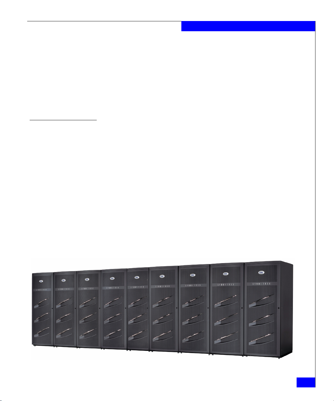
Figure 1 on page 27 provides a front view of the exterior of a
Symmetrix DMX-3 configured with one system bay and eight storage
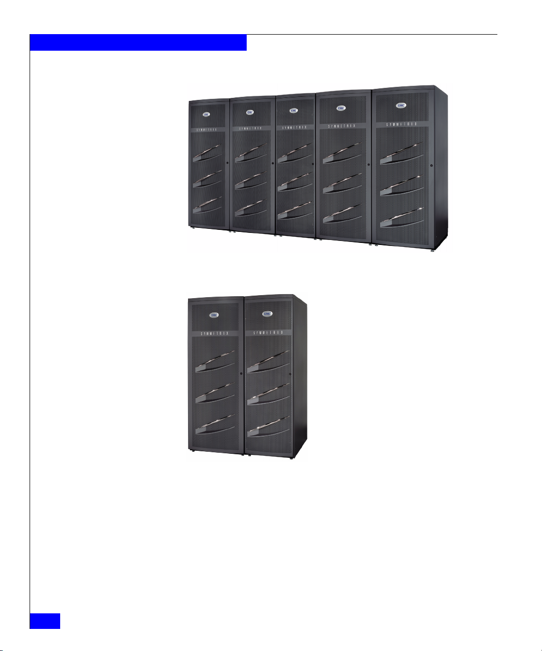
bays. Figure 2 on page 28 provides a front view of the exterior of a
Symmetrix DMX-3 configured with one system bay and four storage
bays. Figure 3 on page 28 provides a front view of the exterior of a
Symmetrix DMX-3 configured with one system bay and one storage
bay.
Chapter 2, “Symmetrix DMX-3 Hardware,” provides more complete
descriptions of the Symmetrix DMX-3.
Figure 1 Symmetrix DMX-3 nine-bay configuration
Symmetrix DMX-3
27
Page 28
Introducing the Symmetrix DMX-3
Figure 2 Symmetrix DMX-3 five-bay configuration
28
Figure 3 Symmetrix DMX-3 two-bay configuration
EMC Symmetrix DMX-3 Product Guide
Page 29

Introducing the Symmetrix DMX-3
Symmetrix hardware
EMC Solutions Enabler Applications Program Interface (API)
Symmetrix-based applications
Host-based Symmetrix applications
Independent software vendor applications
Enginuity operating environment functions
Symmetrix platform and Enginuity operating environment
The Symmetrix DMX hardware architecture (“Symmetrix DMX-3
architecture” on page 53) and the Enginuity
TM
operating
environment are the foundation for the Symmetrix DMX system
storage platform, which consists of the following:
◆ Symmetrix DMX hardware
◆ Enginuity-based operating functions
◆ EMC Solutions Enabler Application Program Interfaces (APIs)
◆ Symmetrix-based applications
◆ Host-based Symmetrix applications
◆ Independent Software Vendor (ISV) applications
Figure 4 on page 29 illustrates the relationships among these software
layers (and Symmetrix hardware).
Figure 4 Enginuity and the storage platform relationships
Enginuity operating environment
Symmetrix Enginuity is the operating environment for the
Symmetrix DMX systems. Enginuity manages and ensures the
optimal flow and integrity of information through the different
hardware components of the Symmetrix system. Enginuity manages
all Symmetrix operations from monitoring and optimizing internal
data flow, to ensuring the fastest response to the user's requests for
information, to protecting and replicating data.
Symmetrix platform and Enginuity operating environment
29
Page 30

Introducing the Symmetrix DMX-3
Enginuity services Enginuity provides the following services for the Symmetrix DMX
systems:
◆ Independently manages system resources to intelligently
optimize performance across a wide range of I/O requirements.
◆ Ensures system availability through advanced fault monitoring,
detection, and correction capabilities and provides concurrent
maintenance and serviceability features.
◆ Interrupts and prioritizes tasks from microprocessors and, for
example, ensures that fencing off failed areas takes precedence
over other operations.
◆ Offers the foundation for specific software features available
through EMC’s disaster recovery, business continuance, and
storage management software.
◆ Provides functional services for both Symmetrix-based
functionality and for a large suite of EMC storage application
software.
◆ Defines priority of each task including basic system maintenance,
I/O processing, application processing (for example,
EMC ControlCenter
®
, SRDF®, TimeFinder®, and EMC
ControlCenter Symmetrix Optimizer).
◆ Provides uniform access through APIs for internal calls and
provides an external interface to allow integration with other
software providers and ISVs.
EMC Solutions Enabler APIs
30
EMC Symmetrix DMX-3 Product Guide
EMC Solutions Enabler APIs are the storage management
programming interfaces that provide an access mechanism for
managing the Symmetrix
third-party storage, switches, and host
storage resources. They enable the creation of storage management
applications that don’t have to understand the management details of
each piece within the total storage environment.
Note: Contact your local EMC Sales Representative or the EMC Powerlink®
website at: http://Powerlink.EMC.com for more information on EMC
storage management APIs
Page 31

Introducing the Symmetrix DMX-3
Storage capacities and global memory requirements
This section describes the Symmetrix DMX-3 storage capacities and
global memory requirements.
Storage capacities
Factors affecting storage capacity
The Symmetrix DMX-3 offers 73 GB, 146 GB, 300 GB, 450 GB, and
500 GB disk drives and can be configured with from 96 to 1,920 disk
drives.
The capacities are based on storage capacity of each disk drive type
and the following storage protection options:
◆ Mirrored (RAID 1)
◆ RAID 10, RAID 1/0
◆ SRDF
◆ RAID 5 (3+1) or RAID 5 (7+1)
◆ RAID 6 (6+2) or RAID 6 (14+2)
Note: Appendix A, “Symmetrix DMX-3 Specifications,” contains additional
information on drive and system capacities.
The following factors affect disk storage capacity:
◆ Drive capacity size
◆ Type of data protection options used
◆ Internal Symmetrix File System (SFS) usage — A Symmetrix
DMX-3 reserves two SFS logical volumes consisting of 6,140
cylinders each (slightly less than 6 GB). These volumes are
protected using mirroring, consuming slightly less than 24 GB
total physical space.
◆ The size of the blocks — 512 or 520 bytes per block
◆ Vault devices — S y m metrix DMX-3 uses vault devices for
vaulting data from global memory during a power-down
operation. Vault devices require 5 GB of space. For each pair of
disk directors in a DMX-3, 160 GB of total capacity is reserved for
vaulting data from memory during system powerdown.
Note: “Configuration rules for vault devices” on page 68 and “Vaulting”
on page 170, contain more information on vaulting.
Storage capacities and global memory requirements
31
Page 32

Introducing the Symmetrix DMX-3
Global memory requirements
The Symmetrix DMX-3 is available with global memory capacity
ranging from 16 GB to 512 GB (256 GB effective). The total global
memory requirement for a Symmetrix DMX-3 is based upon specific
system configurations and customer requirements. Besides the
customer’s applications, other variables that affect the amount of
global memory a Symmetrix DMX-3 requires include the following:
◆ Number of global memory directors
◆ Variable back-end disk director and front-end channel director
board configurations
◆ Various loop configurations for disk drives
◆ Number of disk drives
◆ Disk capacity, including speed and protection type
◆ Number of logical volumes
Your local EMC Sales Representative will assist you in determining
your global memory requirements.
Note: “Global memory directors” on page 83 provides additional
information on memory configurations.
32
EMC Symmetrix DMX-3 Product Guide
Page 33

Performance features
Symmetrix DMX-3 offers improved performance over conventional
Storage Control Unit (SCU) and Direct Access Storage Device
(DASD) designs. Table 2 on page 33 identifies many of the Symmetrix
DMX-3 and Enginuity supported features that enhance performance
and increase throughput.
Tabl e 2 Performance features roadmap (1 of 2)
Feature Document sources
Introducing the Symmetrix DMX-3
Direct Matrix (DMX) Architecture with up to 128 direct
nonblocking data paths and up to 128 GB/s aggregate internal
bandwidth in the DMX-3
Symmetrix DMX-3 global memory directors for optimized
performance
One hundred percent global memory fast write capabilities • “Write operations” on page 110
PermaCache option • “PermaCache option” on page 121
2 Gb/s Fibre Channel Drive Infrastructure • “Fibre Channel disk subsystem” on page 62
• Multiple scalable channel directors, disk directors, and global
memory directors
• ESCON channel speeds up to 17 MB/s
• FICON channel speeds up to 4 Gb/s
• Fibre Channel speeds up to 4 Gb/s
• iSCSI channel speeds up to 1 Gb/s
• Gigabit Ethernet (GigE) remote director speeds up to 1 Gb/s
• GigE IPv4/v6 (IPsec capable) channel speeds up to 1 Gb/s
• FICON Cascading and Open Systems Intermix Configurations
Logical volume capacities • “Symmetrix DMX-3 logical volume capacities” on page 66
Hypervolume Extension option • “Open systems hypervolumes” on page 127
Tiered storage optimization • “Symmetrix Priority Controls” on page 136
a
• “Symmetrix DMX-3” on page 26 and “Symmetrix DMX-3
architecture” on page 53
• “Symmetrix DMX-3 and component scaling attributes” on
page 50
• “DMX-3 point-to-point message matrix” on page 55
• “Global memory performance features” on page 117
• “Memory striping” on page 118
• “Global memory directors” on page 83
• “Global memory director configuration” on page 85
• “Disk mirroring (RAID 1) concepts” on page 191
• “Channel, disk, and global memory directors” on page 75
• “ESCON channel directors” on page 79
• “FICON channel director” on page 80
• “Fibre Channel directors (front-end)” on page 77
• “iSCSI channel directors” on page 82
• “Gigabit Ethernet (GigE) remote directors” on page 81
• “GigE IPv4/v6 (IPsec capable) director” on page 82
• “Symmetrix FICON configurations” on page 94
• “Mainframe systems hypervolumes” on page 132
• “Dynamic Cache Partitioning” on page 137
Virtual LUNs • “Virtual LUN technology” on page 140
ControlCenter • “EMC ControlCenter family of products” on page 150
TimeFinder • “TimeFinder family of products” on page 154
Performance features
33
Page 34

Introducing the Symmetrix DMX-3
Tabl e 2 Performance features roadmap (2 of 2)
Feature Document sources
Dynamic host addressing • “Dynamic Host Addressing” on page 145
Virtual Provisioning • “Virtual Provisioning” on page 146
Tab based Caching (TBC) • “Tag Based Caching (TBC)” on page 119
3380 and 3390 mixed-track geometry • “IBM CKD DASD disk emulation” on page 71
Compatible Parallel Access Volumes (COM-PAVs) • “Parallel Access Volumes” on page 231
Compatible HyperPAV • “Compatible HyperPAV” on page 231
Dynamic Parallel Access Volumes • “Dynamic Parallel Access Volumes” on page 231
PPRC Command Support • “IBM MetroMirror (PPRC)” on page 235
a. Contact your local EMC Sales Representative for currently supported host channel connectivity.
34
EMC Symmetrix DMX-3 Product Guide
Page 35

Introducing the Symmetrix DMX-3
Availability and integrity features
The Symmetrix DMX-3 includes key enhancements that improve the
reliability, availability, and serviceability. Table 3 on page 35
highlights many of the Symmetrix DMX-3 availability and integrity
features.
Tabl e 3 Availability and integrity features roadmap (1 of 2)
Feature Document sources
Proactive Error Detection and Remote Support • “Maintaining data integrity” on page 175
• “Error Checking and Correction, and data integrity protection”
on page 176
• “Disk error correction and error verification” on page 177
• “Global memory director data integrity logic” on page 178
Support for online Enginuity upgrades and updates • “Nondisruptive Enginuity upgrades” on page 173
Fully fault-tolerant design with redundant critical components
and concurrent maintenance support
Channel director redundancy with end-to-end automatic
channel failover and load balancing
Internal Control Data Path redundancy • “Internal control data path redundancy” on page 164
Fibre Channel back-end functionality featuring redundant disk
directors, disk channels, and disk ports
Dual-initiator disk directors • “Dual-initiator feature” on page 168
2N power supply redundancy • “Redundant power subsystem” on page 169
Vaulting • “Configuration rules for vault devices” on page 68
Redundant Global Memory • “Redundant global memory” on page 162
Advanced Communications and Environmental Control
Modules
DMX-3 security features • “Symmetrix Service Credential, Secured by RSA” on page 182
• “Reliability and availability features” on page 162
• “Channel director redundancy” on page 163
• “Fibre Channel back-end redundancy” on page 164
• “Fibre Channel arbitrated loop design” on page 165
• “Vaulting” on page 170
• “DMX-3 communications and environmental control” on
page 89
• “Symmetrix Audit Log” on page 185
• “RSA enVision log security” on page 185
• “EMC Certified Data Erasure for Symmetrix Disks” on
page 186
• “IPsec security features” on page 187
Symmetrix Mirroring option • “Disk mirroring (RAID 1) concepts” on page 191
Availability and integrity features
35
Page 36

Introducing the Symmetrix DMX-3
Tabl e 3 Availability and integrity features roadmap (2 of 2)
Feature Document sources
RAID 5 (3+1), RAID 5 (7+1)
RAID 6 (6+2), RAID 6 (14+2)
RAID 10 data protection options
• “Symmetrix DMX RAID 5” on page 198
• “Symmetrix DMX RAID 6” on page 206
• “Symmetrix RAID 10 for mainframe systems” on page 196
Sparing option • “Dynamic sparing” on page 216
• “Permanent sparing” on page 213
SRDF • “Base SRDF family products” on page 221
• “SRDF family options” on page 222
• Nondisruptive component replacement
• Nondisruptive change or remove drives
• “Nondisruptive component replacement” on page 172
• “Nondisruptively change or remove FBA devices” on page 174
36
EMC Symmetrix DMX-3 Product Guide
Page 37

Serviceability features
Each Symmetrix DMX-3 has an integrated service processor that
continuously monitors the Symmetrix environment. The service
processor communicates with the EMC Customer Support Center
through a customer-supplied direct phone line. The service processor
automatically dials the Customer Support Center whenever the
Symmetrix system detects a component failure or environmental
violation. An EMC Product Support Engineer at the Customer
Support Center can also run diagnostics remotely through the service
processor to determine the source of a problem and potentially
resolve it before the problem becomes critical. Within the DMX-3
control e-net matrix is the Communications and Environmental
Control Module, known as the XCM. The XCM provide the low-level
system-wide communications for running application software,
monitoring, and system diagnostics from the service processor.
Symmetrix DMX systems feature an incrementally scalable design
with a low parts count for quick component replacement, should a
failure occur. This low parts count minimizes the number of failure
points.
The Symmetrix DMX systems feature nondisruptive replacement of
its major components, which can be replaced while the Symmetrix
system is powered on, including:
◆ Channel directors
◆ Disk directors
◆ Global memory directors
◆ Disk adapters
◆ Channel adapters
◆ Disk drives
◆ Power supplies
◆ Power Distribution Units (PDU)
◆ Power Distribution Panels (PDP)
◆ Power supply/ cooling module for drive enclosure
◆ Battery backup modules
◆ Cooling fan modules
◆ Communications and Environmental Control (XCM) modules
◆ Service processor components:
Introducing the Symmetrix DMX-3
• Keyboard
• Video Display and Mouse
Note: Chapter 2, “Symmetrix DMX-3 Hardware” and “Nondisruptive
component replacement” on page 172 provide more information on these
components.
Serviceability features
37
Page 38

Introducing the Symmetrix DMX-3
Supported software applications
Enginuity is what enables simultaneous connection to virtually all
mainframe, UNIX, Windows, iSeries, and Linux platforms—and all
validated in EMC’s interoperability labs. The result: you can do
whatever you want with your information. Centralize it. Re-purpose
it. Consolidate it. Replicate it. Share it. Distribute and manage it. Put
it to work where it’s relevant, anytime without compromise.
Enginuity is the solid foundation of EMC’s storage software
offering—and the driving force behind the operational consistency
and nondisruptive features across Symmetrix.
The software offerings are divided into these categories:
◆ “Tiered Storage Optimization” on page 38
◆ “Storage management” on page 39
◆ “Symmetrix local and remote replication software solutions” on
page 39
◆ “Information mobility” on page 40
Tiered Storage Optimization
38
EMC Symmetrix DMX-3 Product Guide
Note: Product information on these software options are available on the
EMC Powerlink website at:
http://Powerlink.EMC.com
All of the software products are furnished under a license. Refer to
the copyright page in this product guide for the complete licensing
statement. For software license, model numbers, prerequisites, and
additional information, contact your local EMC Sales Representative.
EMC delivered two software products with the latest version of
Enginuity (5772) that optimize performance with multi-tiered
Symmetrix systems. Dynamic Cache Partitioning provides dedicated
memory resource allocation. Symmetrix Priority Controls help
manage multiple application workloads by setting priority levels for
device groups, allowing higher-priority applications to have faster
response times than lower priority applications.
Note: “Tiered Storage Optimization” on page 136 contains related
information.
Page 39

Introducing the Symmetrix DMX-3
Storage management
Symmetrix local and remote replication software solutions
Storage Management Console is an intuitive, browser-based GUI for
Symmetrix device management for open systems as well as
z/OS-attached systems. Symmetrix Management Console features
management and monitoring of local and remote replication, as well
as the tiered storage optimization tools Symmetrix Priority Controls
and Dynamic Cache Partitioning.
The EMC ControlCenter family of storage management software,
provides automated management of your multi-vendor networked
storage environment through a single, consistent, information-centric
approach.
EMC z/OS Storage Manager (EzSM) is a mainframe software
product providing discovery and viewing of your Symmetrix
environment. EzSM provides facilities to handle volumes, data sets,
catalogs, and detailed Symmetrix functionality information.
Note: See “EMC ControlCenter family of products” on page 150 for related
information.
The EMC TimeFinder and SRDF families of software are the most
powerful suites of local and remote storage replication solutions
available in the industry; enabling business continuance volumes for
parallel processing activities like backup, testing and development,
and local restore, as well as remotely replicated copies to guard
against primary site disasters and outages.
Note: “TimeFinder family of products” on page 154 contains related
information. “Base SRDF family products” on page 221 and “SRDF family
options” on page 222 contains related information.
Supported software applications
39
Page 40

Introducing the Symmetrix DMX-3
Information mobility
Copy and move data to where it provides the most value. Symmetrix
DMX enables online data mobility and migration while minimizing
complexity and disruption. Move data between storage tiers,
platforms, and sites quickly, efficiently, and without disruption:
◆ EMC Open Migrator/LM — Provides host-based, nondisruptive
data migration/data mobility at the volume level for Microsoft
Windows and UNIX servers.
◆ EMC Open Replicator for Symmetrix — Enables remote
point-in-time copies to be used for high-speed data mobility,
remote vaulting, migrations, and distribution between EMC
Symmetrix DMX and qualified storage systems with full or
incremental copy capabilities.
◆ SRDF/Data Mobility (DM) — Enables rapid transfer of data from
source volumes to remote volumes anywhere in the world.
Note: Product information on these software options are available on the
EMC Powerlink website at:
http://Powerlink.EMC.com
Note: “Base SRDF family products” on page 221 and “SRDF family options”
on page 222 contain related information.
40
EMC Symmetrix DMX-3 Product Guide
Page 41

Hardware options
Titan Titan
SYM-001247
Storage Bay
(Mohawk)
SYMMETRIX
EMC
2
PS1 P
S2 P
S3
PS4
PS5
PS6
PS7
PS8
System Bay
(Titan)
EMC
2
Introducing the Symmetrix DMX-3
The following hardware options are offered with the DMX-3 systems:
◆ DMX-3 Silencer
◆ DMX-3 Systems Securing Kits
DMX-3 Silencer
The Symmetrix DMX-3 Silencer as shown in Figure 5 on page 41 is a
fan noise reduction option for the Symmetrix DMX-3 system bay and
storage bay systems. The Symmetrix DMX-3 Silencer is designed
with leading edge sound reducing materials that attenuate
high-frequency noise components and reduce overall sound levels. It
is designed not to affect airflow or thermal performance.
Figure 5 DMX-3 Silencer
Hardware options
41
Page 42

Introducing the Symmetrix DMX-3
Tabl e 4 DMX-3 Silencer kits model information
Table 4 on page 42 provides the DMX-3 Silencer kits model
information.
Model Number Description Comments
TB24-Silencer System bay silencer kit 1 kit per bay
SB-Silencer Storage bay silencer kit 1 kit per bay
The DMX-3 Silencer kit contains the following components:
◆ DMX-3 Silencer for top of system bay and or storage bay
◆ Full length foam piece for the storage bay
◆ An 11-in. by 20-in. foam piece for the system bay
Note: Contact your EMC Sales Representative for Silencer kit information
and current availability.
DMX-3 Silencer specifications
Tabl e 5 DMX-3 Silencer physical specifications
DMX-3 silencer for system bay Dimensions
DMX-3 silencer for storage bay Dimensions
Table 5 on page 42 lists the dimensions and weight for the DMX-3
Silencer for the system bay and storage bay.
Height
Width
Depth
Weight Pounds
Height
Width
Depth
Weight Pounds
Table 47 on page 267 lists the sound power and sound pressure levels
for the DMX-3 system bay and storage bays.
Inches
8.25
23
36.5
10
Inches
6.5
29
36.5
9.4
Centimeters
20.96
58.42
92.71
Kilograms
4.54
Centimeters
16.51
73.66
92.71
Kilograms
4.26
42
EMC Symmetrix DMX-3 Product Guide
Page 43

Introducing the Symmetrix DMX-3
DMX-3 systems securing kits
Some customers require that their EMC equipment be installed to
withstand significant shock and vibration. Installation of EMC
Symmetrix DMX-3 systems securing kits in combination with
adequate substrate construction, will mitigate collateral damage
during such events.
The kits contain heavy brackets plus hardware used to attach the
brackets to the frames of the system and storage bays. The brackets
are attached to the floor using bolts that engage the flooring
substructure provided by the user.
Symmetrix DMX-3 systems securing kits can be installed to system
and storage bays without lifting the bays.
Note: Please refer to the EMC Symmetrix DMX-3 Physical Planning Guide for
information regarding the EMC securing kits, or contact your EMC Sales
Representative for specific information.
Hardware options
43
Page 44

Introducing the Symmetrix DMX-3
44
EMC Symmetrix DMX-3 Product Guide
Page 45

Invisible Body Tag
2
Symmetrix DMX-3
Hardware
This chapter describes the main hardware components of the
Symmetrix DMX-3 including:
◆ Major components ............................................................................. 46
◆ Symmetrix DMX-3 architecture....................................................... 53
◆ Symmetrix channel connectivity and host integration................. 59
◆ Fibre Channel disk subsystem ......................................................... 62
◆ Channel, disk, and global memory directors................................. 75
◆ Symmetrix DMX-3 power subsystems ........................................... 86
◆ DMX-3 communications and environmental control................... 89
◆ Channel attachments ......................................................................... 92
Symmetrix DMX-3 Hardware
45
Page 46

Symmetrix DMX-3 Hardware
WARNING
Major components
The Symmetrix DMX-3 is a disk array subsystem that is composed of
a system bay and from one to eight storage bays. This section
describes the Symmetrix DMX-3 components.
Tabl e 6 Symmetrix DMX-3 model component overview
Symmetrix DMX-3 components Component information location
Main component locations of the system bay, front and rear views Figure 6 on page 47
Main component descriptions of the system bay Table 7 on page 48
Main component locations of the storage bay, front and rear views Figure 7 on page 49
Main component descriptions of the storage bay Table 8 on page 50
To reduce the risk of personal injury, do not open the doors or move
the Symmetrix DMX-3 unless you are qualified and familiar with
safety procedures for electrical equipment and the Symmetrix
DMX-3. The Symmetrix DMX-3 contains no user-serviceable parts.
Neither the system bay nor the storage bays should not be moved or
opened for any reason by untrained persons. If the Symmetrix DMX-3
is in need of relocation or repair, only qualified personnel should
access components inside the bays or move them.
46
EMC Symmetrix DMX-3 Product Guide
Page 47

PS1 PS2 PS3 PS4 PS5 PS6 PS7 PS8
LAN1
LAN2
PS8 PS7 PS6 PS5 PS4 PS3 PS2 PS1
ON
I
OFF
O
ON
I
OFF
O
ON
I
OFF
O
ON
I
OFF
O
ON
I
OFF
O
ON
I
OFF
O
Fans Fans
Power supplies
*KVM
UPS
*Server
SYM-000978
Power zone B
left side
Power zone A
right side
Disk directors,
Channel directors,
and Global memory
directors in 24-Slot
card cage
**Battery backup unit
assemblies
**Battery backup unit
modules
Disk adapters,
Channel adapters,
and Environmental
and communication
modules (XCM)
Power distribution
panels
Power
distribution
units
System bay front System bay rear
* The service processor consists of the KVM and the server.
** The battery backup unit assembly consists of two battery backup unit modules.
Symmetrix DMX-3 Hardware
Figure 6 Symmetrix DMX-3 system bay (interior view, front and rear)
Major components
47
Page 48

Symmetrix DMX-3 Hardware
Tabl e 7 Symmetrix DMX-3 system bay component overview
Component Description
Cooling fan modules Three 3-fan modules maintain air circulation and cool the unit internally.
Card cage and midplane The front 24 slots contain global memory directors, disk directors, and channel directors (front-end
Fibre Channel, ESCON, FICON, and iSCSI channel directors
a
, or GigE Remote directors). The rear
slots contain the channel host adapters, GigE Remote adapters, disk adapters, and the
Communications and Environmental Control Modules (XCMs).
Channel directors/adapters
and remote director
adapters
(front-end)
a
Up to 12 channel directors connect to the front side of the midplane and the adapters to the rear
side of the midplane in the system cabinet. Each channel director’s adapter provides the interface to
the host or network.
Fibre Channel Disk
Directors/Adapters
(Back-End)
Two, four, six or eight disk directors connect to the midplane in the front of the cabinet. Each disk
director’s adapter provides the interface to the Fibre Channel disk drives. The adapter connects to
the opposite side of the midplane in the rear of the cabinet.
Global memory directors Two, four, six, or eight global memory directors provide up to 512 GB (256 GB effective) total global
memory, available in 8 GB, 16 GB, 32 GB, and 64 GB global memory director capacities.
Communications and
environmental control
module (XCM)
Two communications and environmental control modules (XCMs) connect to the midplane in the
rear card cage. The XCM contains the Ethernet interface between the directors (channel, disk, and
memory) and the service processor. It monitors and logs environmental events for all Symmetrix
DMX-3 FRUs (field replacable units) and reports any operational problems such as thermal
excursion, voltage drop, etc. It also has connectors for paths between the XCM and the BBU
modules (in the system bay and the storage bays) for sending commands and receiving status.
Power supplies Up to eight power supplies support the system bay and are split between two (A and B) three-phase
power zones. Each zone supports up to four power supplies. One zone can maintain power for the
entire system bay independent of the power supplies in the other zone. The DMX-3 is available in
three-phase Delta or three-phase WYE configurations.
Power distribution panel
(PDP), power distribution
unit (PDU), and AC
connectors
Two PDPs, one for each zone, provide a centralized cabinet interface and distribution control of the
AC power input lines when connected to the system bay PDUs. The PDPs contain the manual
On/Off power switches, which are accessible through the rear door. The PDUs, one for each power
zone, provide the main interface between the input AC from the PDPs and the various components
contained within the system bay.
Battery backup unit (BBU)
assembly consisting of two
BBU modules
Service processor
(keyboard, video display,
and mouse - KVM), server,
and uninterruptible power
supply (UPS)
Up to eight BBU modules provide backup for each of the power supplies. If AC power fails, the BBU
modules can maintain power for two 5-minute periods of AC loss while the Symmetrix system shuts
down.
The service processor consists of a KVM and a server that connects to the Symmetrix subsystem
through an Ethernet interface. The service processor uses an external modem for communicating
with the EMC Customer Support Center when the Symmetrix system detects an error condition.
The service processor is used to download the Symmetrix system configuration to the directors and
provides diagnostic and maintenance utilities for the Symmetrix system. The server battery backup
is provided by a UPS.
a. Contact your local EMC Sales Representative for current channel director availability.
48
EMC Symmetrix DMX-3 Product Guide
Page 49

Symmetrix DMX-3 Hardware
Battery backup
unit (BBU) modules
Disk drives,
15 per drive
enclosure
Drive enclosure
covers
BBU assembly
cover
Storage bay front
Storage bay rear
! !
EXP PRI
EXP PRI
EXP PRI
EXP PRI
#
#
!
!
!
#
EXP PRI
EXP PRI
! !
EXP PRI
EXP PRI
#
!
!
#
EXP PRI
EXP PRI
! !
EXP PRI
EXP PRI
#
!
!
#
EXP PRI
EXP PRI
! !
EXP PRI
EXP PRI
#
!
!
#
EXP PRI
EXP PRI
! !
! !
! !
! !
!
#
EXP PRI
EXP PRI
! !
EXP PRI
EXP PRI
#
!
!
#
EXP PRI
EXP PRI
! !
EXP PRI
EXP PRI
#
!
!
#
EXP PRI
EXP PRI
! !
EXP PRI
EXP PRI
#
!
!
#
EXP PRI
EXP PRI
! !
OFF
O
I
ON
OFF
O
I
ON
OFF
O
I
ON
! !
! !
! !
EXP PRI
EXP PRI
#
!
!
#
EXP PRI
EXP PRI
! !
EXP PRI
EXP PRI
#
!
!
#
EXP PRI
EXP PRI
! !
EXP PRI
EXP PRI
#
!
!
#
EXP PRI
EXP PRI
! !
! !
! !
! !
EXP PRI
EXP PRI
#
!
!
#
EXP PRI
EXP PRI
! !
EXP PRI
EXP PRI
#
!
!
#
EXP PRI
EXP PRI
! !
EXP PRI
EXP PRI
#
!
!
#
EXP PRI
EXP PRI
! !
! !
! !
! !
BBU modules
OFF
O
I
ON
OFF
O
I
ON
Power supply/
System cooling
OFF
O
I
modules
ON
Power distribution
units (PDUs)
Link control
cards (LCCs)
Power distribution
panels (PDPs)
! !
EXP PRI
EXP PRI
#
!
!
#
EXP PRI
EXP PRI
! !
! !
EXP PRI
EXP PRI
#
!
!
#
EXP PRI
EXP PRI
! !
! !
Power zone B
left side
Power zone A
right side
Figure 7 Symmetrix DMX-3 storage bay (interior view, front and rear)
Major components
SYM-000977
49
Page 50

Symmetrix DMX-3 Hardware
Table 8 Symmetrix DMX-3 storage bay component overview
Component Description
Drive enclosures The Symmetrix DMX-3 storage bay is configured with capacities of 120 or 240 disk drives. Each
drive enclosure includes the following components:
• Redundant power and cooling modules for disk drives
• Two Link Control Cards (LCC)
• From 4 to 15 Fibre Channel disk drives per drive enclosure
The storage bays can be populated with any combination of DMX disk drives (73 GB, 146 GB, and
300 GB 10,000 rpm drives; 73 GB, 146 GB, and 300 GB, and 450 GB 15,000 rpm drives; and 500
GB 7,200 rpm drives) Some configuration restrictions may apply.
Battery backup unit (BBU)
modules
Power distribution panel (PDP),
Power distribution unit (PDU),
and AC connectors
Two BBU modules are required for four drive enclosures (up to eight BBU modules support up to
16 drive enclosures in one storage bay). The BBU modules provide backup power to the drive
enclosures.
Two PDPs, one for each zone, provide a centralized cabinet interface and distribution control of the
AC power input lines when connected to the storage bay PDUs. The PDPs contain the manual
On/Off power switches, which are accessible through the rear door. The PDUs, one for each
power zone, provide the main interface between the input AC from the PDPs and the BBU
modules to the drive enclosures contained within the storage bay.
Symmetrix DMX-3 and component scaling attributes
The Symmetrix DMX-3 base configurations are composed of a system
bay and independent storage bays, that have common configuration
guidelines. Any DMX-3 base configuration accommodates the later
addition (upgrade) of capacity through the on-line addition of drives,
drive enclosures, if required, and additional storage bays that support
up to 1,920 2 Gb/s or 4 Gb/s disk drives. The Direct Matrix
™
infrastructure accommodates nondisruptive addition of disk directors
(increasing from two to eight disk directors) enabling increased
capacity when needed.
The DMX-3 consists of a system bay and from one to eight storage
bays. The DMX-3 system bay has from two to eight disk directors, up
to 12 channel directors (combined director total 16), and two, four, six,
or eight global memory directors. The system bay also contains up to
eight power supplies, each of which has a dedicated 2.2 kW BBU.
Table 9 on pa ge 51 describes the available DMX-3 configurations.
50
EMC Symmetrix DMX-3 Product Guide
Page 51

Symmetrix DMX-3 Hardware
Tabl e 9 DMX-3 configurations
Number of disk directors 2 disk directors 4 disk directors 6 disk directors 8 disk directors
Drive channels 8 162432
Minimum and maximum
number of disk drives 96–240 192–960 360–1,440 480–1,920
Minimum and maximum
TB capacity (raw)
Maximum TB capacity
(protected)
a
b
7.04–119.90 14.08–479.62 26.40–719.43 35.21–959.54
102 301 435 525.1
Maximum global memory
(usable) 64 GB 144 GB 216 GB 256 GB
Usable connectivity
d
48 x 4 Gb/s Fibre
Channel
64 x 4 Gb/s Fibre
Channel
64 x 4 Gb/s Fibre
Channel
64 x 4 Gb/s Fibre
24 x 4 Gb/s FICON 48 x 4 Gb/s FICON 40 x 4 Gb/s FICON 32 x 4 Gb/s FICON
48 ESCON 64 ESCON 64 ESCON 64 ESCON
8 x 1 Gb/s Ethernet
remote replication
24 x 1 Gb/s Gigabit
Ethernet iSCSI
a. Minimum raw capacity for a DMX-3 is based on 73 GB disk drives and maximum capacity is based on 500 GB disk drives.
b. Maximum protected capacity for a DMX-3 is based on RAID 5 (7+1) data protection configurations, allowance for vault devices, and
Symmetrix file system (SFS) requirements.
c. Based 1,920 500 GB drives.
d. Combinations may be limited or restricted.
DMX-3 configuration rules and guidelines
The following are some of the system configuration rules and
guidelines to consider when planning your new or upgrading your
DMX-3:
8 x 1 Gb/s Ethernet
remote replication
48 x 1 Gb/s Gigabit
Ethernet iSCSI
8 x 1 Gb/s Ethernet
remote replication
40 x 1 Gb/s Gigabit
Ethernet iSCSI
8 x 1 Gb/s Ethernet
remote replication
32 x 1 Gb/s Gigabit
Ethernet iSCSI
c
Channel
◆ All bays must be configured in an inline installation. Each bay is
bolted to the adjacent bays during installation.
◆ Storage bays can be populated with any combination of 73 GB,
146 GB and 300 GB 10,000 rpm drives, 73 GB, 146 GB, 300 GB,
450 GB 15,000 rpm drives, and 500 GB 7,200 rpm drives. Some
restrictions may apply.
◆ A minimum of four (4) disk drives must be configured in each
drive enclosure.
Major components
51
Page 52

Symmetrix DMX-3 Hardware
◆ While all drives (different capacities or different speeds) can be
intermixed in Symmetrix DMX-3 systems, locations on disk
director pairs and drive loops may affect application
performance. Consult your Symmetrix representative for
guidelines on optimal configuration of mixed drive sizes and
speeds.
◆ 5 GB on the first 4 drives of every drive loop (160 GB per disk
director pair) is reserved for memory vaulting.
◆ The first four disk drives on each drive loop in the direct-attached
storage bay support the memory vault devices.
◆ 24 GB of total capacity is reserved for internal Symmetrix File
System (SFS) use.
◆ Symmetrix systems support various data protection methods:
• RAID 1 — Mirrored pairs of two hypervolumes
• RAID 1/0 — Mirroring and striping for open system
environments
• RAID 10 — Data striped across four mirrored pairs of
hypervolumes for mainframe environments
• RAID 5 (3+1) or RAID 5 (7+1) — Data striped on four or eight
hypervolumes with rotating parity
• RAID 6 (6+2) or RAID 6 (14+2) — Data striped on eight or
sixteen hypervolumes with rotating parity
• SRDF — Data mirrored to another Symmetrix
• Dynamic sparing — Increases data availability by copying the
data on a failing volume to a spare volume until the original
device is replaced
• Permanent sparing — Replaces a faulty drive automatically
from a list of available spares residing in the Symmetrix
system without CE involvement on site
52
Note: Chapter 5, “Data Integrity, Availability, and Protection,” provides
more information and configuration rules regarding the above data
protection options.
◆ Consider details of space, power and installation requirements as
well as planning for future system expansion. Appendix C
“Planning and Installation,” and the EMC Symmetrix DMX-3
Physical Planning Guide provide details on these topics.
EMC Symmetrix DMX-3 Product Guide
Page 53

Symmetrix DMX-3 architecture
The Symmetrix DMX-3 features a high-performance, Direct Matrix
Architecture (DMX) supporting up to 128 point-to-point serial
connections within the DMX system.
Symmetrix DMX technology is distributed across all channel
directors, disk directors, and global memory directors in Symmetrix
DMX systems. Enhanced global memory technology supports
multiple regions and 16 connections on each global memory director.
In the Direct Matrix Architecture, contention is minimized because
control information and commands are transferred across a separate
and dedicated message matrix. The major components of Symmetrix
DMX architecture are the front-end channel directors (and their
interface adapters), global memory directors, and back-end disk
directors (and their interface adapters).
The matrix midplane provides configuration flexibility through the
slot configuration. Each director slot port is hard-wired
point-to-point to one port on each global memory director board.
This section includes the following topics:
Symmetrix DMX-3 Hardware
DMX-3 block diagram
◆ “DMX-3 block diagram” on page 53
◆ “DMX-3 configuration rules and guidelines” on page 51
◆ “DMX-3 point-to-point message matrix” on page 55
◆ “DMX-3 slot configuration” on page 57
In a fully configured Symmetrix DMX-3, each of the eight director
ports on the sixteen directors connects to one of the 16 memory ports
on each of the eight global memory directors. These 128 individual
point-to-point connections facilitate up to 128 concurrent global
memory operations in the system. Figure 8 on page 54 illustrates the
point-to-point architecture and the interconnection of the major
components of the Symmetrix DMX-3 systems.
Symmetrix DMX-3 architecture
53
Page 54

Symmetrix DMX-3 Hardware
Battery backup
unit odules
Cooling
ESCON Director
ESCON Host Atta c h
Direct
Matrix
Direct
Matrix
FC Director
FC Host Atta c h
Direct
Matrix
Direct
Matrix
MultiP r otocol C D
Direct
Matrix
Direct
Matrix
MultiP r otocol C D
FICON , GigE , iSCS I
Direct
Matrix
Direct
Matrix
MultiP r otocol C D
FICON , GigE , iSCS I
Direct
Matrix
Direct
Matrix
MultiP r otocol C D
FICON , GigE , iSCS I
Direct
Matrix
Direct
Matrix
FC Director
FC Host Atta c h
Direct
Matrix
Direct
Matrix
ESCON Director
ESCON Host Atta c h
Direct
Matrix
Direct
Matrix
Cntl
FC (Ba c k-End )
Symmetrix
FC disk d e vice s
Direct
Matrix
Direct
Matrix
Cntl
FC (Ba c k-End )
Symmetrix
FC Disk D e vice s
Direct
Matrix
Direct
Matrix
Cntl
FC (BE or FE)
Symmetrix
FC disk devices*
Direct
Matrix
Direct
Matrix
Cntl
FC (BE or FE)
Symmetrix
FC disk devices*
Direct
Matrix
Direct
Matrix
Cntl
FC (BE or FE)
Symmetrix
FC disk d e vices *
Direct
Matrix
Direct
Matrix
Cntl
FC (BE or FE)
Symmetrix
FC disk d e vices *
Direct
Matrix
Direct
Matrix
Cntl
FC (Ba c k-End )
Symmetrix
FC disk d e vice s
Direct
Matrix
Direct
Matrix
Cntl
FC (Ba c k-End )
Symmetrix
FC disk d e vice s
Direct
Matrix
Direct
Matrix
Cntl
Cntl Cntl Cntl Cntl Cntl Cntl Cntl
Cont r ol and comm unications signal s
Cont r ol and comm unications signal s
32 GB
Global
memor y
32 GB
Global
memor y
32 GB
Global
memor y
32 GB
Global
memor y
32 GB
Global
memor y
32 GB
Global
memor y
32 GB
Global
memor y
32 GB
Global
memor y
E n vironmenta l
control and
status ignals
(XCM)
*Note : The DMX-4 system suppor ts Fibre Channel , FICON , ESCON , and iSCSI connections as well as GigE , Fibre Channel , and ESCON remote connections .
The DMX-4 system midplane has f our slots that suppo r t either f r ont-end c hannel directo r s or ba c k-end disk directo r s .
E n vironmenta l
control and
status signals
(XCM)
FICON , GigE , iSCS I
Power supplies
Service
processor
(KVM & server)
UPS
Modem
Figure 8 Symmetrix DMX-3 block diagram
54
EMC Symmetrix DMX-3 Product Guide
Page 55

Symmetrix DMX-3 Hardware
DMX-3 point-to-point message matrix
Symmetrix DMX systems feature a point-to-point interconnect
technology for its separate matrix fabrics, which have been
implemented for both data plane functions and control plane
functions. This Symmetrix DMX message matrix provides high
bandwidth and low latency control plane communication, which
manages the data movement through the Symmetrix system.
Figure 9 on page 56 is a simplified view of the Symmetrix DMX
message matrix. The message fabric is made up of several fabric
elements, or FE, connected together so that all end nodes are
connected to a unique port on the outer edge of the message fabric.
The end nodes are commonly referred to as the Message Engine or ME.
The ME is an integral part of the CPU controller and allows the
front-end and back-end processors to communicate with each other
through the message fabric.
The message fabric is managed by a fabric manager, which provides
initialization for the fabric elements, real-time monitoring, and
diagnostic functions. The fabric manager is assigned to any one of the
director processors and communicates to the fabric through special
in-band fabric management packets.
Symmetrix DMX-3 architecture
55
Page 56

Symmetrix DMX-3 Hardware
Message
fabric
FE FE
XCM0
FE
FE
FE
FE
XCM1
FE
FE
FE
FE
FE
A B C D
FE
A B C D
Front-end
hannel director
Back-end
disk director
Back-end
disk director
Front-end
cdannel Director
Fabric
Manager
Figure 9 Symmetrix DMX-3 message fabric
DMX-3 midplane slot configuration
The front of the Symmetrix DMX-3 card cage midplane contains the
channel directors, disk directors, and global memory directors. The
rear card cage midplane contains the adapters, and the
Communications and Environmental Control Module (XCM) pair.
56
EMC Symmetrix DMX-3 Product Guide
Page 57

Symmetrix DMX-3 Hardware
Dir
T ype
BE
Dir
T ype
FE
Dir
T ype
BE
Dir
T
ype
FE
Dir
ype
FE
Dir
T
ype
BE
Dir
T T ype
FE
or
Dir
Ty pe Type Type
BE
Dir
T T ype
BE
Dir
FE
Dir
ype
BE
Dir Dir
Dir
BE
M0
M1
M7 M6 M5 M4 M3
M2
FE*
or
FE*
or or
FE* FE*
BE FE
1 8 7 6 5 4 3 2
9
16 13
12 11 10
Dir
Type
14
Dir
Type
15
SYM-000085
FE
Type
FE
Ty pe
Global memory directors
M0 through M7
Director pairs
Global memory Director pairs
*Note: These slots (Directors 5, 6, 11, and 12) in the midplane can be configured with either front-end or back-end directors.
The Symmetrix DMX systems require certain board types to occupy
particular slot locations within the card cage. Adhering to the
configurations stated for each model type ensures that the physical
routing of the serial signals minimizes contention for memory
resources, maximizes bandwidth within the system, and maintains
total redundancy to the same memory location through two
completely different hardware paths. Termination of TTL and GTLP
signals occurs at the adapters in the end slot locations.
DMX-3 slot configuration
The Symmetrix DMX-3 midplane provides eight slots in the center of
the midplane reserved for global memory directors and the
remaining 16 slots are reserved for channel directors and disk
directors (eight to the left and eight to the right of memory). Figure 10
on page 57 shows the card cage layout for the global memory
directors, the Front-End (FE) and Back-End (BE) designations for the
Fibre Channel directors, and the FE designations for the ESCON
directors, FICON directors, iSCSI, or GigE Remote directors.
Figure 10 Symmetrix DMX-3 card cage configurations (front)
Symmetrix DMX-3 architecture
57
Page 58

Symmetrix DMX-3 Hardware
Adapter pairs
SYM-000078
Adp
16
Type
BE
Adp
15
Type
BE
Adp
14
Ty pe
FE
Adp
13
Type
FE
Adp
12
Ty pe
BE
or
FE*
Adp
11
Type
BE
or
FE*
Adp
6
Type
BE
or
FE*
Adp
5
Type
BE
or
FE*
Adp
10
Type
FE
Adp
9
Type
FE
Adp
8
Type
FE
Adp
7
Type
FE
Adp
4
Ty pe
FE
Adp
3
Type
FE
Adp
2
Type
BE
Adp
1
Type
BE
XCM
1
XCM
0
Type
FE
Type
FE
*Note: These slots (Ad
apters 12, 11, 6, and 5) in the midplane can be configured with either front-end or back-end apapters.
On the rear side of the midplane Figure 11 on page 58, the adapters
reside behind their respective directors, and two slots behind the
memory are reserved for the XCM pair.
58
Figure 11 Symmetrix DMX-3 card cage configurations (rear)
EMC Symmetrix DMX-3 Product Guide
Page 59

Symmetrix DMX-3 Hardware
Symmetrix channel connectivity and host integration
The Symmetrix DMX-3 can be integrated with all major enterprise
hosts and servers. This section outlines the emulations and hosts
Symmetrix systems support through Fibre Channel, iSCSI, ESCON,
FICON, or GigE (SRDF) interfaces.
Note: For the most current information on Symmetrix systems and specific
host integration, contact your local EMC Sales Representative, or refer to the
EMC Powerlink website.
Channel connectivity
Open systems
connectivity
Mainframe systems
connectivity
IBM iSeries Fibre
Channel connectivity
The Symmetrix DMX-3 supports connectivity to mainframe and open
systems hosts.
Note: The Symmetrix Enterprise Storage Platform (ESP) software enabler, a
software option, is required if you plan to store and access mainframe and
open systems data on the same Symmetrix system. For more information on
the ESP option, contact your local EMC Sales Representative.
The Symmetrix DMX-3 connects to Fibre Channel and iSCSI open
system host interfaces such as UNIX, Windows, Linux, and iSeries
systems.
Note: Contact your local EMC Sales Representative for availability of iSeries
host connectivity.
The Symmetrix DMX-3 supports ESCON and FICON host
connectivity to mainframe systems.
With the Symmetrix Fibre Channel adapter, users are able to connect
Symmetrix systems through fibre to the iSeries 270 and 8xx models.
When using directly connected fibre devices (point-to-point) the
maximum distance is 500 m.
The DMX-3 systems support Fibre Channel connectivity to iSeries
systems. Fibre Channel is currently capable of running up to 2 Gbs/s
full duplex with iSeries systems.
Note: For information on disk drives supported for iSeries systems, contact
your EMC Sales Representative.
Symmetrix channel connectivity and host integration
59
Page 60

Symmetrix DMX-3 Hardware
Symmetrix channel configurations
Supported Fibre Channel interfaces
Supported cluster hosts
EMC offers the following Symmetrix DMX-3 channel directors:
◆ Eight-port ESCON directors
◆ Eight-port Fibre Channel directors
◆ Multiprotocol Channel Director (MPCD) that supports:
• FICON host connections
• iSCSI host connections
• GigE SRDF connections
• GigE IPv4/v6 (IPsec capable) connections
• Fibre Channel connections
Table 17 on page 77 describes DMX-3 channel director configurations.
The Symmetrix DMX systems Fibre Channel interfaces attach to most
open systems and iSeries hosts that have Fibre Channel connectivity.
Note: Consult your local EMC Sales Representative for the most current list
of supported hosts, models, operating systems, and EMC open systems host
support policies, or refer to the EMC Powerlink website.
For the most recent information on supported cluster hosts, refer to
the EMC Powerlink website.
Mainframe serial channel interfaces
60
EMC Symmetrix DMX-3 Product Guide
Symmetrix serial channel interfaces attach to IBM S/370, S/390
(ES/9000, 309X, 308X, 43XX, and 9370), the plug-compatible
manufacturer (PCM) equivalent, Amdahl, Unisys, Bull, and Siemens.
Note: “Channel attachments” on page 92 contains a more detailed discussion
of channel attachment options.
Table 10 on page 61 shows the IBM DASD models and controllers
that Symmetrix systems emulate.
Page 61

Tabl e 1 0 IBM controller/DASD compatibility
❏ IBM controller ❏
IBM DASD 3990-6 2105 2107
a
3380
3390-1 X X X
3390-2 X X X
3390-3 X X X
3390-9 X X X
3390-27 X X
3390-54 X X
a. Contact your local EMC Sales Representative for information on 3380 support.
XXX
Symmetrix DMX-3 Hardware
Supported mainframe operating systems
In IBM/PCM mainframe environments, the Symmetrix DMX system
is operating-system independent. The memory processing algorithms
are self-managed, and the Symmetrix system does not depend on
host cache commands to benefit from read and write caching.
Almost every S/370 and z/OS operating system can be supported,
including:
TPF AIX/ESA MVS/ESA MVS/SP MVS/XA
MVT/VSE VM/ESA VM/HPO VM/SP VM/XA
VSE/ESA VSE/SP z/OS z/OS.e z/VM
Symmetrix DMX systems also support the following mainframe
operating systems:
GC0S7 GCOS8 LINUX for z/Series MSP OS/1100
PICK TPF
a. Contact your local EMC Sales Representative for availability of TPF support.
a
UTS
Symmetrix channel connectivity and host integration
61
Page 62

Symmetrix DMX-3 Hardware
Fibre Channel disk subsystem
The Symmetrix DMX-3 disk subsystem are contained in the storage
bays. They are fully redundant components and can be replaced
nondisruptively. The disk subsystems consist of the following
components:
◆ Disk drives — One-inch low-profile 2 Gb/s Fibre Channel disk
drives available in 73 GB, 146 GB, 300 GB, 450 GB, and 500 GB
sizes. A fully populated drive enclosure holds 15 disk drives and
16 drive enclosures per storage bay.
◆ Two link control cards (Fibre Channel interface cards).
◆ Two power supply/cooling modules.
The drive enclosure supports 2 Gb/s back-end fibre interface
(FC-AL). The dual-loop configuration provides redundancy, port
bypass capability, and disk access up to 2 Gb/s per loop.
Disk drives
The Symmetrix DMX-3 uses industry-standard 2 Gb/s Fibre Channel
disk drives for physical disk drives. The disk drives are installed in
the front of storage bays and connect to a midplane. Each disk drive
is integrated with a dual-port Fibre Channel Arbitrated Loop (FC-AL)
controller with Fibre Channel interface that transports SCSI protocol.
The Symmetrix DMX-3 supports Fibre Channel loops ranging from
15 drives to 60 drives per loop. Table 11 on page 63 lists the features
for each type of Symmetrix DMX-3 disk drive.
62
EMC Symmetrix DMX-3 Product Guide
Page 63

Symmetrix DMX-3 Hardware
Tabl e 1 1 Symmetrix DMX-3 disk drive features
Disk capacity
and
rotational speed
Interface
73 GB
10 K / 15 rpm
146 GB
10 K / 15 K rpm
2 Gb/s FC 2 Gb/s FC 2 Gb/s FC 2 / 4 Gb/s FC 2 Gb/s FC
maximum data
transfers per port
Internal data rate
megabits per
b
second
Average access
time (read/write)
a
ms
Device-level data
470–944/685–1,142 470–944/685–1,142 470/944 1.95 Gb/s (max) 470/944
4.7–5.4/3.5–4.0 4.7–5.4/4.7–5.4 4.7/5.4 3.4–4.1 8.5/9.5
16 MB 32 MB 32 MB 16 MB 32 MB
buffer
a. Contact your EMC Sales Representative for the latest drive specifications.
b. These specifications are subject to change.
Link control cards (LCC)
The link control card’s main function is to provide services to the
drive enclosure, which includes the capability to control functionality
and monitor environmental status. Each drive enclosure has two
LCCs. The LCC performs the following functions:
◆ Individual Fibre Channel disk poweron and poweroff functions
◆ Loop configuration control
◆ Failover control
◆ Marker LED control
◆ Individual disk port control
◆ Drive presence detection
◆ Reporting of temperature and voltage status information
◆ RS-232 monitoring of the BBU modules that support the
components in the storage bay
300 GB
10 K / 15K rpm
a
450 GB
15K
500 GB
7.2 K rpm
Power supply/ cooling module
Two power supply/cooling modules provide all necessary power
and cooling to the 15 disk drives in the disk enclosure in an N+1
configuration.
Fibre Channel disk subsystem
63
Page 64

Symmetrix DMX-3 Hardware
Symmetrix DMX disk drive capacities
Precise storage capacity values depend on:
◆ Whether the user configures the disk to emulate an open systems
device or a mainframe 3390 device.
◆ Whether the user calculates a gigabyte to equal:
• 1,000 * 1,000 * 1,000 bytes
• or 1,024 * 1,024 * 1,024 bytes
◆ The number of logical volumes configured on the disk.
◆ Data protection option used: (RAID 1, RAID 5 (3+1), RAID 5
(7+1), RAID 6 (6+2), RAID 6 (14+2), RAID 10, RAID 1/0, and
SRDF).
Table 12 on page 65 shows the available Symmetrix cylinders and
storage capacities for 73 GB, 146 GB, 300 GB, 450 GB, and 500 GB disk
drives based on the open systems, mainframe, and iSeries
emulations. When calculating total system capacity, the following
must also be included: 24 GB of total capacity is reserved for internal
Symmetrix File System use. From 160 to 640 GB of total capacity is
reserved for vaulting data from memory during system power down.
Each DMX-3 system requires a minimum of two global spare drives
and one additional global spare drive for every 100 disk drives or a
portion thereof. For example, a DMX-3 with 547 disk drives requires
2 + 6= 8 global spare drives.
64
EMC Symmetrix DMX-3 Product Guide
Page 65

Symmetrix DMX-3 Hardware
The GB values shown in Table 12 on page 65 are based on the
following conventions: The GB
1024 bytes. The GB
value is based on 1 GB = 1000 * 1000 * 1000
10
value is based on 1 GB = 1024 *1024 *
2
bytes. Although the open systems GB values are expressed
differently, they are equivalent.
a
450 GB
15K
500 GB
7.2K
Disk size
and speed (rpm)
Tabl e 1 2 Symmetrix DMX-3 disk drive capacities
73 GB
10K or 15K
146 GB
10K or 15K
300 GB
10K or 15K
Raw Capacity 73.41 GB 146.82 GB 300 GB 450.00 500 GB
10
449.643 GB
10
499.6 GB
Formatted capacity
(open systems in GB
) 73.34 GB
10
146.69 GB
10
10
299.76 GB
Formatted capacity
(open systems in GB2) 68.30 GB
136.62 GB
2
2
279.17 GB
2
418.763 GB
2
465.29 GB
Cylinders (open systems) 74,611 149,227 304,932 457,764 508,626
Formatted capacity
(mainframe systems, 3380
emulation)
a
69.88 GB
139.77 GB
10
10
285.60 GB
10
443.87 GB
10
476.00 GB
Cylinders
(mainframe systems, 3380
emulation)
a
98,134 196,269 401,052 601,578 668,420
Formatted capacity
(mainframe systems, 3390
emulation)
72.40 GB
144.81 GB
10
10
295.91 GB
10
443.87 GB
10
493.19 GB
Cylinders
(mainframe systems, 3390
emulation)
85,189 170,379 348,150 522,225 580,251
10
2
10
10
Formatted capacity
72.82 GB
145.66 GB
10
10
292.46 GB
10
438.702 GB
10
(iSeries emulation)
a. Contact your local EMC Sales Representative for information on 3380 emulations, disk drives, and data protection methods.
Fibre Channel disk subsystem
N/A
65
Page 66

Symmetrix DMX-3 Hardware
Symmetrix DMX-3 logical volume capacities
The maximum number of logical volumes supported on Symmetrix
DMX-3 physical disk drives depends on the data protection used.
Table 13 on page 66 describes the logical volumes supported on
Symmetrix DMX disk drives.
Tabl e 1 3 Logical volumes supported on Symmetrix DMX-3 disk drives
Symmetrix DMX-3 disk drives and data protection
Logical volumes per disk drive with SRDF Protection (without local data protection) 160
Logical volumes per disk drive with RAID 1 Protection 173
Logical volumes per disk drive with RAID 5 (3+1) Protection 255
Logical volumes per disk drive with RAID 5 (7+1) Protection 255
Logical volumes per disk drive with RAID 6 (6+2) Protection 255
Logical volumes per disk drive with RAID 6 (14+2) Protection 255
Logical volumes per disk drive with RAID 10 Protection (mainframe data volumes only) 255
a. For information on Symmetrix DMX-3 data protection options, refer to Table 28 on page 189.
Note: “Open systems hypervolumes” on page 127 or “Mainframe systems
hypervolumes” on page 132 contain more information on logical volumes.
Configuration requirements for Symmetrix systems vary according to the
applications used. To configure logical volumes for optimum Symmetrix
system performance, consult your local EMC Sales Representative.
a
Maximum logical volumes
66
The Symmetrix DMX-3 can support up to 64,000 logical volumes,
depending on the number of disk directors, the type of data
protection, and hardware configuration. Table 14 on page 67
describes the maximum logical volumes supported on DMX-3
systems by the number of drives, DA boards, and type of data
protection employed.
Note: “Logical volumes supported for DMX-3 systems” on page 67 shows
the maximum logical volumes available for the Symmetrix DMX-3 with the
number of disk drives stated and a homogeneous protection scheme on those
disk drives. The logical volume limit is a function of the number of disk
directors, disk drives, Enginuity level, and data protection type. Consult your
local EMC Sales Representative for currently supported logical volumes for
DMX-3 systems.
EMC Symmetrix DMX-3 Product Guide
Page 67

Symmetrix DMX-3 Hardware
Maximum number
of disk drives
Tabl e 1 4 Logical volumes supported for DMX-3 systems
Number of DA
boards
Data protection Maximum logical volumes per system
1,920 8 SRDF 64,000
1,920 8 RAID 1 64,000
1,920 8 RAID 5 (3+1) 64,000
1,920 8 RAID 5 (7+1) 32,768
1,920 8 RAID 6 (6+2) 30,720
1,920 8 RAID 6 (14+2) 15,360
1,920 8 RAID 10 16,000
1,440 6 SRDF 64,000
1,440 6 RAID 1 64,000
1,440 6 RAID 5 (3+1) 49,152
1,440 6 RAID 5 (7+1) 24,576
1,440 6 RAID 6 (6+2) 23,040
1,440 6 RAID 6 (14+2) 11,520
1,440 6 RAID 10 16,000
960 4 SRDF 64,000
960 4 RAID 1 64,000
960 4 RAID 5 (3+1) 32,768
960 4 RAID 5 (7+1) 16,384
960 4
960 4
960 4
240 2
240 2
240 2
240 2
240 2
240 2
240 2
RAID 6 (6+2)
RAID 6 (14+2)
RAID 10
SRDF
RAID 1
RAID 5 (3+1)
RAID 5 (7+1)
RAID 6 (6+2)
RAID 6 (14+2)
RAID 10
15,360
7,680
16,000
20,760
20,760
15,300
7,650
3,840
1,920
7,650
Fibre Channel disk subsystem
67
Page 68

Symmetrix DMX-3 Hardware
Configuration rules for vault devices
Vault devices are volumes on designated physical disk drives that
reserve a dedicated 5 GB space for vaulting data including metadata.
The following configuration rules apply to the vaulting drives and
disk directors:
◆ Each disk director pair requires 32 such dedicated devices for a
total of 160 GB of vault space per disk director pair.
◆ The vault devices can only use single-mirror data protection and
cannot be configured with TimeFinder/Snap, virtual, or dynamic
spare devices.
◆ Vault drives are eligible for permanent sparing if there is a valid
spare on the same port. The vault device cannot be moved to a
different loop, but it can be moved to a different location on the
same loop. “Permanent sparing” on page 213 contains additional
information
◆ The drive pool, virtual devices, or drive devices cannot reside in
the 5 GB of vault space. However, they can reside on the same
physical disk drive as the vault devices but not within the vault
devices.
◆ The distribution of the vault devices across the disk directors, the
back-end interfaces, and the physical disks should be such that a
full vault will be possible within the time frame dictated by the
capacity of the battery (up to five minutes).
◆ The total capacity of all of the vault hypervolumes in the system
will be at least sufficient to keep two logical copies of the
persistent part of global memory.
Symmetrix DMX disk drive emulations
68
EMC Symmetrix DMX-3 Product Guide
Symmetrix DMX systems support connectivity to mainframe systems
and open systems hosts. When the Symmetrix DMX systems are
configured to open systems hosts such as UNIX, Windows, Linux, or
iSeries the Symmetrix disk drives emulate standard disk drives.
When the Symmetrix DMX systems are configured to IBM
z/OS/PCM system hosts, the Symmetrix disk drives emulate IBM
CKD DASD.
Note: The Symmetrix Enterprise Storage Platform (ESP) software enabler, a
software option, is required if you plan to store and access mainframe and
open systems data on the same Symmetrix system.
Page 69

Symmetrix DMX-3 Hardware
Deleting (and then adding) devices online
Open system disk emulation
FBA data and
command format
Enginuity supports removing and then adding devices online, which
facilitates the following configuration enhancements:
◆ Change Device Emulation Online — Remove a CKD volume and
add an FBA volume.
◆ Convert between mirrored and RAID protected volumes.
◆ The optimal order is to delete devices and then add. If done in the
reverse order, unnecessary global memory will be allocated for
the deleted devices.
◆ When attempting to add or delete devices, or change protection
type of devices, a new minimum cache value will be calculated.
In rare cases this new value could prohibit the changes until
additional memory is added to the system.
On open systems hosts, the Symmetrix DMX logical disk volumes
appear as standard SCSI disk drives with data stored in Fixed Block
Architecture (FBA) format. All host logical volume manager software
can be used with Symmetrix disk volumes. The following paragraphs
describe the FBA disk format and logical volume structure.
Fixed Block Architecture (FBA) disk drives store data in fixed-sized
blocks (typically 512 bytes). A disk drive using FBA format is viewed
as a large array of blocks. The physical position of each block
(cylinder and track) is usually not significant to the host. When
requesting disk access for read or write, the host addresses a file by
the logical block address (LBA) of the starting block and a count of
the total blocks used by the file. Symmetrix channel directors and
disk directors control access to global memory and disk drives,
responding to host requests as a standard disk drive.
Logical volume
structure (open
systems)
Note: Disk drives in Symmetrix DMX systems attached to iSeries hosts are
configured in 520-byte blocks.
The channel directors interact with global memory. Therefore, there is
no physical meaning to cylinders, tracks, and heads on the
Symmetrix logical volume from the front-end point of view.
However, Symmetrix systems use a logical geometry definition for
their logical volume structure. This geometry is reflected in the mode
sense data available to the host.
Fibre Channel disk subsystem
69
Page 70

Symmetrix DMX-3 Hardware
Symmetrix systems use the following logical volume structure:
◆ Each logical volume has n cylinders
◆ Each cylinder has 15 tracks (heads)
◆ Each track has 128 blocks of 512 bytes
Therefore, a Symmetrix logical volume with n cylinders has a usable
block capacity of:
n * 15 * 128
n for each volume is defined during Symmetrix configuration.
To calculate the size of the logical volume:
Number of cylinders * heads * blocks * 512
(n * 15 * 128* 512)
Note: “Open systems hypervolumes” on page 127 provides information on
configuring open systems logical volumes.
Flexible device
geometry
(for Sun Solaris hosts)
Flexible device geometry improves interoperability when migrating
data between DMX-3 or DMX-4 and older Symmetrix systems. When
the Symmetrix DMX-3 was introduced, the disk geometry presented
to the host by the disk array changed. The number of sectors per track
was doubled to 128, which also led to a doubling of the cylinder size.
In the Sun Solaris operating system, disk geometry, disk size,
manufacturer ID, and the partition table are stored in the label in
sector 0 of the disk. The label is written to the disk using the format
utility, which makes a device usable to the OS. When a Solaris device
is opened for I/O activity, the label is written to host cache and the
SCSI driver uses the partition information to translate relative
partition addresses to device absolute logical block addresses.
The difference between disk geometries will not cause issues in most
scenarios. However, there are three pieces of information contained in
the disk label that, if modified, can cause a new label to be written by
the operating system. If disk geometry, manufacturer ID, or the size
of the disk drive change, format will write a new label if “auto
configure” is run from the format> type menu, followed by label.
When a device is migrated to a DMX-4 or DMX-3 using a product
that produces a track-by-track copy of the source device on the target
device (SRDF, RecoverPoint, or Open Replicator for example), the
entire device is migrated including the VTOC label. When this occurs
between devices with heterogeneous disk geometries, there will be a
difference between the disk geometry written in the label on the
target (which was copied from the source) and the disk geometry that
70
EMC Symmetrix DMX-3 Product Guide
Page 71

Symmetrix DMX-3 Hardware
is presented to the target host by the DMX-4 or DMX-3. If the device
is re-labeled, there may be potential issues with data availability.
This is because Solaris reserves two cylinders from every device for
use by the operating system. DMX-4 and DMX-3 cylinders are twice
as large as cylinders from previous generation Symmetrix disk
arrays, meaning that the operating system will overwrite the last 1920
sectors of the user data area with an area reserved for operating
system use. It should be noted that, regardless of a difference in
geometry between the label and the actual disk, no issue will be seen
if the disk is not re-labeled by the user. This potential issue has been
resolved with the introduction of Flexible Device Geometry.
To alleviate any potential for corruption, two features have been
added to Symmetrix Enginuity. A bin file setting has been included
that allows the DMX-3 and DMX-4 to present an external device
geometry for all Symmetrix devices that is identical to the device
geometry of earlier Symmetrix arrays. Functionality has also been
added to Enginuity that allows alternate disk geometry to be
presented on a device by device basis.
Note: Contact your EMC Customer Engineer to determine if this feature
should be enabled on your Symmetrix DMX system.
IBM CKD DASD disk emulation
The Symmetrix DMX system appears to mainframe operating
systems as a 3990-6, 2105, or 2107 controller. The physical disk drives
can appear to the mainframe operating system as a mix of multiple
3390 and 3380 device types. All standard models of the 3380 or 3390
volumes can be emulated up to the physical volume sizes installed.
Fibre Channel disk subsystem
71
Page 72

Symmetrix DMX-3 Hardware
A single Symmetrix system can simultaneously support both 3380
and 3390 device emulations. Table 15 on page 72 lists the Symmetrix
characteristics for some standard IBM device emulation modes.
Symmetrix systems also support nonstandard device sizes, as long as
the cylinder count does not exceed that of the equivalent IBM device
type.
Contact your EMC Sales Representative for 3380 support.
Note: Appendix A “Symmetrix DMX-3 Specifications,”contains more IBM
DASD emulation characteristics.
Tabl e 1 5 IBM DASD emulation characteristics
IBM DASD model MB/volume Bytes/track Bytes/cylinder Cylinders/volume
a
3390-54
3390-27 27,844 56,664 849,960 32,760
3390-9 8,514 56,664 849,960 10,017
3390-3 2,838 56,664 849,960 3,339
3390-2 1,892 56,664 849,960 2,226
55,688 56,664 849,960 65,520
72
3390-1 946 56,664 849,960 1,113
a
3380K
a. Contact your local EMC Sales Representative for currently supported IBM Controller/DASD emulation modes and 3380 support.
Mixed track
geometries
1,891 47,476 712,140 2,655
You can configure a Symmetrix DMX system with both 3380 and 3390
track geometries on the same disk device (3380 and 3390 devices
cannot be defined in the same SSID or LCU). A single disk device can
contain up to 255 logical volumes, depending on the data protection
used.
Note: “Mainframe systems hypervolumes” on page 132 contains
information on configuring mainframe logical volumes.
IBM/PCM data and
command formats
All Symmetrix systems support the count-key-data (CKD) and
extended count-key-data (ECKD) format used by IBM 3390 and 3380
DASD. For a full description of the channel command words (CCW)
supported, refer to the IBM 3390 Storage Control Reference. Figure 12
on page 73 shows the CKD track format emulated for 3390 and 3380
DASD.
EMC Symmetrix DMX-3 Product Guide
Page 73

Symmetrix DMX-3 Hardware
Index
marker
R0
Magnetic
disk
Figure 12 Track format for 3390 DASD
HA D
KC
Track format
All tracks are written with formatted records. The start and end of
each track are defined by the index marker. Each track has the same
basic format as that shown in Figure 12 on page 73. That is, it has an
index marker, home address (HA), record zero (R0), and one or more
data records (R1 through Rn). These track formats are discussed in
the following sections.
Information is recorded on all Symmetrix disk drives in an emulation
format chosen at configuration. Each track contains certain nondata
information (such as the address of the track, the address of each
record, the length of each record, and the gaps between each area),
and data information.
Index marker — An index marker indicates the physical beginning
and end of each track for each disk drive (Figure 12 on page 73).
Index
marker
R1
KCD
Home address (HA) — There is one home address on each track that
defines the physical location of the track by specifying the track
address (cylinder and head location) and the condition of the track
(flag byte). The flag byte indicates whether the track is usable,
defective, or an alternate track.
Record zero–r0 (track descriptor record) — This is the first record
after the home address. The Count field indicates its physical location
(cylinder and head), record number, key length, and data length. In
general, the key length is zero bytes and the data length is eight.
Data records (R1 through Rn) — All remaining records on a track are
data records. The Count field indicates the data record's physical
location (cylinder and head), record number, key length, and data
length. The key is optional and, when used, contains information
used by an application. The data area contains the user data. To
determine the number of records a track can hold, refer to the IBM
3390 Direct Access Storage Introduction or IBM 3380 Direct Access
Storage Introduction for the equations for calculating this number.
Fibre Channel disk subsystem
73
Page 74

Symmetrix DMX-3 Hardware
Track capacity Track capacity is the maximum capacity achievable when there is one
physical data record per track formatted without a key. Because the
track can contain multiple data records, additional Address Markers,
Count Areas, and gaps reduce the number of bytes available for data.
The track capacity is the number of bytes left for data records after
subtracting the bytes needed for the home address, record zero,
address marker, count area, cyclic check (for error correction), and the
gaps for one data record.
For 3390 emulations, the track capacity is 56,664 bytes. For 3380
emulations, the track capacity is 47,476 bytes.
74
EMC Symmetrix DMX-3 Product Guide
Page 75

Channel, disk, and global memory directors
This section describes the Symmetrix DMX-3 directors. The channel
directors and global memory directors manage the storage control
functions. The disk directors handle the data storage functions.
Symmetrix DMX-3 Hardware
Channel director connectivity
The Symmetrix DMX-3 provides channel connectivity through
combinations of mainframe systems and open systems channel
directors. These include:
◆ Fibre Channel directors (also used with SRDF)
◆ ESCON directors
◆ ESCON directors used for SRDF, data migration, and the SDMS
™
(Symmetrix Data Migration Service) application
◆ Multiprotocol Channel Directors (MPCD) available with these
channel connection combinations:
• Fibre Channel
•FICON
•iSCSI
• GigE (Gigabit Ethernet) remote directors used for SRDF
• GigE IPv4/v6 (IPsec capable) directors
Note: The Symmetrix DMX-3 supports mixed ESCON, FICON, Fibre
Channel, and iSCSI interfaces when the required Symmetrix ESP software is
installed on the Symmetrix system. Contact your local EMC Sales
Representative for currently supported host connectivity.
The Symmetrix DMX-3 supports open systems hosts such as UNIX
systems, Linux systems, and Windows connectivity through
Symmetrix Fibre Channel or iSCSI directors. (iSeries connectivity is
only supported through Fibre Channel directors.) The Symmetrix
DMX-3 supports mainframe connectivity through ESCON and
FICON directors. The Symmetrix DMX-3 connects directly to host
processors through physical channel attachments. Table 16 on
page 76 describes the protocols that are supported by the Symmetrix
DMX-3 channel directors.
Channel, disk, and global memory directors
75
Page 76

Symmetrix DMX-3 Hardware
Tabl e 1 6 Supported protocols and Symmetrix DMX-3 channel directors
Protocol
4 Gb/s Fibre Channel host/SAN ports 2-64 1-8 per Fibre Channel Director
2 Gb/s Fibre Channel remote replication ports 2-8 1-4 per Fibre Channel Director
1 Gb/s iSCSI ports 2-32 1-4 per Multiprotocol Channel Director
1 Gb/s GigE remote replication ports 2-8 1-4 per Multiprotocol Channel Director
1 Gb/s GigE IPv4/v6 (IPsec capable) 2-8 1-4 per Multiprotocol Channel Director
4 Gb/s FICON host ports 2-32 1-4 per Multiprotocol Channel Director
ESCON host ports 2-80 1-8 per ESCON Channel Director
ESCON remote replication ports 2-8 1-4 per ESCON Channel Director
a. Contact your local EMC Sales Representative for ESCON channel director and GigE Remote support availability.
b. Usable ports are per qualified channel directors.
a
Usable system ports
b
Ports per channel director
Channel director descriptions
Symmetrix DMX-3 channel directors are single boards that occupy
one slot on the Symmetrix midplane. All channel directors interface
to host channels through interface adapter cards connected to the
opposite side of the midplane. The Symmetrix DMX-3 supports up to
12 channel directors.
Note: Appendix C “Planning and Installation,”provides information on
mainframe and open systems channel director configurations. Contact your
local EMC Sales Representative for specific supported configurations.
All channel directors contain four high performance processor
complexes. The channel directors process data from the host and
manage access to global memory over a direct matrix (DMX)
technology (Figure 8 on page 54). Each channel director on the
Symmetrix DMX-3 supports eight internal links to global memory.
DMX technology is used across the Symmetrix system, as it is also
designed into each global memory director. In addition to DMX
technology, each director includes support for a separate message
matrix for the transfer of control information.
Note: “DMX-3 point-to-point message matrix” on page 55 and
“DMX-3 communications and environmental control” on page 89
provide information on the Symmetrix DMX message matrix.
Table 17 on page 77 describes the DMX-3 channel director models.
76
EMC Symmetrix DMX-3 Product Guide
Page 77

Symmetrix DMX-3 Hardware
Tabl e 1 7 Symmetrix DMX-3 channel director models and descriptions
Fibre
Description
Model number
DMX3-80000B 8-port Fibre Channel (FC) Director (8 MM ports) 8
DMX3-71000B 8-port Fibre Channel Director (7 MM /1 SM port) 7 1
DMX3-62000B 8-port Fibre Channel Director (6 MM/2 SM ports) 6 2
DMX3-00004B 4-port FICON Channel Director (4 SM ports) 4
DMX3-00040B 4-port FICON Channel Director (4 MM ports) 4
DMX3-00103B 4-port MPCD
DMX3-00400 4-port GigE or iSCSI Channel Director (4 MM ports) 4
DMX3-ESCD8 8-port ESCON DIR (8 MM ports) N/A N/A N/A N/A N/A
DMX3-40002B 6-port MPCD (4 FC MM. port/2 FICON SM ports) 4 2
DMX3-40200B 6-port MPCD (4 FC MM. ports/2 GigE or iSCSI MM ports) 4 2
DMX3-60100B 7-port MPCD (6 FC MM. ports/1 GigE or iSCSI MM ports) 6 1
DMX3-00103BS 4-port MPCD (1 GigE IPv4/v6 (IPsec capable) MM port/ 3 FICON SM
ports)
DMX3-00400S 4-port GigE or iSCSI Channel Director (4 GigE IPv4/v6
(IPsec capable) MM ports)
DMX3-40200BS 6-port MPCD (4 FC MM ports/ 2 GigE IPv4/v6 (IPsec capable) MM
ports)
DMX3-60100BS 7-port MPCD (6 FC MM ports/ 1 GigE IPv4/v6 (IPsec capable) MM
port)
a. Contact your local EMC Sales Representative for currently supported host channel directors and GigE remote directors.
b. MM = multimode. SM = single-mode.
c. MPCD = Multiprotocol Channel Director.
c
(1 GigE or iSCSI MM port/3 FICON SM ports) 1 3
a
Channel
b
GigE FICON
MM SM MM MM SM
13
4
42
61
Fibre Channel directors (front-end)
The Fibre Channel front-end director has eight FC ANSI compliant,
4 Gb/s (also configurable to 2 Gb/s, and 1 Gb/s) Fibre Channel
interfaces for connection to host systems. The director has eight
high-speed paths to global memory. The Fibre Channel director
interfaces to the host channels through an eight-port Fibre Channel
interface adapter and is available in single-mode and multimode
configurations (Table 17 on page 77). Each Symmetrix DMX Fibre
Channel director supports eight internal links to global memory. Data
transfers between host and global memory can execute concurrently
across all Fibre Channel ports on a director. Table 18 on page 78 lists
Channel, disk, and global memory directors
77
Page 78

Symmetrix DMX-3 Hardware
Tabl e 1 8 Symmetrix devices and addressing capabilities
Maximum Symmetrix devices and device addresses
Symmetrix devices per processor complex 4,096
Symmetrix devices per Fibre Channel director 16,384
Addresses range per port 0–4,095 (0x000–0xFFF)
a. Each Fibre Channel front-end director has four processor complexes.
the Fibre Channel front-end support capabilities for directors, their
Symmetrix devices, and their addressing.
for Fibre Channel front-end directors
Maximum Symmetrix devices per front-end
Fibre Channel processor complex
Note: The numerical values for Symmetrix devices stated in Table 18 on
page 78 are the maximum allowed according to the architectural limits of the
microcode running on the Fibre Channel front-end director. The actual limits
allowed for customer environments will be lower and are dependent on the
host type, HBA and driver type/version, and overall system implementation.
Also, note that using metadevices will reduce the number of host-visible
volumes for a given number of devices (Symmetrix Devices) configured to
the Fibre Channel front-end director; that is, each member of the metadevice
will be counted to the allowed limit of devices configured to a Fibre Channel
front-end director
the EMC Powerlink website.
. For information on Fibre Channel host attachments, go to
a
Fibre Channel adapters (front-end)
Fibre Channel
directors for SRDF
iSeries Fibre Channel
Connectivity
78
EMC Symmetrix DMX-3 Product Guide
The Symmetrix DMX-3 can support up to eight qualified Fibre
Channel directors. Contact your local EMC Sales Representative for
specific supported configurations.
The Symmetrix DMX-3 Fibre Channel adapters provide the
connectivity between the host channels and the Fibre Channel
front-end director through optical transceiver connections.
Note: Symmetrix Fibre Channel directors currently support connections to a
number of hosts supporting Fibre Channel connectivity. For a current list of
supported hosts, go to the EMC Powerlink website.
The Fibre Channel host director can be Enginuity-configured as the
link between Symmetrix units in a Symmetrix Remote Data Facility
(SRDF) configuration. The Fibre Channel director interfaces to
Symmetrix channels through the Fibre Channel interface adapter.
The Symmetrix Fibre Channel Adapters, through fibre, connect to the
iSeries 270 and 8xx models. When using directly connected fibre
devices (point-to-point) the maximum distance is 500 m in 1 Gb/s
mode.
Page 79

Symmetrix DMX-3 Hardware
ESCON channel directors
The Symmetrix DMX-3 ESCON director has eight ESCON channel
interfaces for connection to host systems and eight high-speed paths
to global memory. The ESCON channel director interfaces to the host
channels through an eight-port ESCON channel interface adapter
and supports data transfer rates up to 17 MB/s per port.
The Symmetrix ESCON director can support up to 1,024 logical paths
per port when only the A port of the A and B ports of the processor is
configured and up to 512 logical paths per port when both the A and
B ports are configured.
Note: Contact your local EMC Sales Representative for ESCON channel
director availability.
The Symmetrix DMX-3 may support 2 to 10 ESCON channel
directors. Table 19 on page 79 describes the ESCON channel
configurations supported in the DMX-3.
Tabl e 1 9 ESCON director configurations
A and B port enabled A port enabled
Maximum LCU (logical control units) per port 16 (00 to 0F) 16 (00 to 0F)
Maximum LCUs per Symmetrix system 250 250
Maximum devices per LCU 256 256
Maximum logical paths per port 512 1,024
Maximum logical paths per LCU per port 32 64
Maximum DMX channel addresses per one or two ports 2,048 + 2,048 2,048
Maximum DMX channel addresses per Symmetrix system consisting of up to
64,000 base devices (physical devices) with up to 255 aliases (logical devices)
Maximum concurrent I/O host connections per Symmetrix DMX system
a. The maximum concurrent I/O connections is based on 10 ESCON directors. Contact your local EMC Sales Representative for specific
supported configurations.
a
64,000 64,000
80 40
SDMS support The Symmetrix ESCON director supports the SDMS (Symmetrix
Data Migration Service) application for migrating data over ESCON
channels from one Symmetrix system to ESCON channels on another
Symmetrix system.
Channel, disk, and global memory directors
79
Page 80

Symmetrix DMX-3 Hardware
Multiprotocol Channel Directors
FICON channel director
The Symmetrix DMX-3 Multiprotocol Channel Director (MPCD),
through mezzanine card technology, supports Fibre Channel, GigE,
GigE IPv4/v6 (IPsec capable), iSCSI, and FICON protocols on
Symmetrix DMX systems.
The MPCD implements a flexible mezzanine card that delivers highly
configurable support for FICON channels to mainframe systems,
Fibre Channel connections to open systems configurations, or Gigabit
Ethernet support for iSCSI, or SRDF over IP connections.
Note: Contact your local EMC Sales Representative for currently supported
protocols. Table 17 on page 77 describes the supported Multiprotocol models.
FICON channel directors support native mode point-to-point
connections and FICON native mode switched point-to-point
connections to IBM 9672, G5/G6, z/900, and z/990 systems running
z/OS, z/VM, VM/ESA, and VSE/ESA operating systems. FICON
employs ESCON protocols that have been mapped to the FC-4
upper-level protocol layer of the Fibre Channel architecture. FICON
supports multiple concurrent I/O connections, channel program
multiplexing, and better link utilization than ESCON path switching.
FICON allows the consolidation of multiple ESCON channels into
one FICON channel.
The FICON mezzanine card provides up to four single-mode or
multimode LC bidirectional (full duplex) connections. Symmetrix
FICON channels transfer data at speeds up to 4 Gb/s.
80
Note: “Symmetrix FICON configurations” on page 94 contains information
on additional configuration options.
The Symmetrix DMX FICON design auto-detects 4 Gb/s, 2 Gb/s or
1 GB/s at switch or channel port login time.
The Symmetrix DMX-3 system may support up to eight FICON
channel directors. Table 20 on page 81 describes the FICON channel
director configurations supported in the DMX-3.
EMC Symmetrix DMX-3 Product Guide
Page 81

Symmetrix DMX-3 Hardware
Tabl e 2 0 FICON director configurations
Maximum LCUs (logical control units) per port 64 (00 to FE)
Maximum LCUs per Symmetrix system 250
Maximum devices per LCU 256
Maximum logical paths per port 8,192
Maximum logical paths per LCU per port 128
Maximum DMX channel addresses per port 8,192
Maximum DMX channel addresses per Symmetrix system, base and alias 64,000
Maximum I/O host connections per Symmetrix DMX system
a. The maximum I/O connections are based on 8 FICON directors for the DMX-3. Contact your local EMC Sales Representative for specific
supported configurations.
a
32
Gigabit Ethernet (GigE) remote directors
GigE remote mezzanine cards on the MPCD enable remote director
functionality based upon Gigabit Ethernet technology that enable
direct Symmetrix-to-IP network attachment and eliminate the need
for expensive media converter appliances.
GigE support for SRDF on Symmetrix DMX systems:
◆ Increases the options for Symmetrix-to-Symmetrix connectivity.
◆ Allows the Symmetrix system to connect to your existing
Ethernet infrastructure and directly access high-speed data
transmission conduits using Internet Protocol (IP).
◆ Supports SRDF traffic to one or more remote Symmetrix systems
that also have GigE remote directors installed.
◆ Supports TCP/IP protocols and function layers.
◆ Is fully compatible with the SRDF protocols and other Symmetrix
DMX directors, drives, software, and protection schemes.
Symmetrix DMX GigE remote channels for SRDF transfer data at
speeds up to 1 Gb/s. The GigE director provides up to four 1 Gb/s
Ethernet ports and connects using LC connectors. It is compatible
with Symmetrix DMX-2 and Symmetrix 8000 systems.
Channel, disk, and global memory directors
81
Page 82

Symmetrix DMX-3 Hardware
GigE IPv4/v6 (IPsec capable) director
iSCSI channel directors
The GigE IPv4/v6 (IPsec capable) channel director provides support
for the latest Internet Protocol standards, including IPsec (Internet
Protocol Security) and IPv6. The embedded line-grade encryption
co-processor provides strong security without degrading
performance. Preshared encryption keys simplify management while
maintaining security for data in transit.
These directors can co-exist in the same system with any existing
DMX-3 channel directors. With the new director, IPsec can be enabled
on a port-by-port basis. IPsec is enabled through a separately
purchased software license.
The IP Stack version can be similarly configured per port. No
additional software license is required.
The number of IPsec sessions will be limited to 100 per port. IPsec can
be enabled for SRDF connections. IPsec enabled and IPsec disabled
channel directors can co-exist in the same Symmetrix.
“IPsec security features” on page 187 contains additional
information on IPsec.
The Symmetrix DMX-3 MPCD, through mezzanine card technology,
supports iSCSI channel connectivity by way of Gigabit Ethernet
(GigE) hardware for the Symmetrix DMX systems. The iSCSI channel
director supports iSCSI channel connectivity to IP networks and to
iSCSI-capable open systems server systems for block storage transfer
between hosts and storage. The primary applications are storage
consolidation and host extension for stranded servers and
departmental workgroups. Symmetrix GigE remote channels for
SRDF transfer data at speeds up to 1 Gb/s. The Symmetrix iSCSI
director provides up to four 1 Gb/s Ethernet ports and connects
using LC connectors.
82
The iSCSI directors support the iSNS protocol, a mechanism that
provides Naming and Discovery services for iSCSI initiators. The
iSNS server information is configured in the Symmetrix IMPL file for
each iSCSI director. Each iSCSI director must register itself with the
iSNS server, which provides:
◆ A mechanism to query iSNS server to find other hosts/targets
◆ Support for State Change Notification and Status Inquiry
The iSCSI director supports TCP/IP protocols and function layers. It
is fully compatible with the SRDF protocols and other Symmetrix
DMX directors, drives, software, and protection schemes.
EMC Symmetrix DMX-3 Product Guide
Page 83

Symmetrix DMX-3 Hardware
Fibre Channel disk directors (back-end)
Global memory directors
The Symmetrix DMX-3 Fibre Channel back-end disk directors
manage the interface to the disk drives, and are responsible for data
movement between the disk drives s and global memory. Each disk
director on a Symmetrix DMX system supports eight internal links to
global memory.
The Symmetrix DMX-3 features a 2 Gb/s Fibre Channel back-end
infrastructure. The Fibre Channel disk director has eight multiplex
processors that support one port each on its back adapter.
The Symmetrix DMX-3 is available with two, four, six, or eight disk
directors, supporting Fibre Channel loops ranging from 15 drives to
60 drives per loop.
Note: For information on maximum logical volumes supported on each
Symmetrix DMX physical disk drive and the maximum logical volumes
supported for each Symmetrix DMX model, refer to “Symmetrix DMX-3
logical volume capacities” on page 66.
The Symmetrix DMX-3 global memory director technology is one of
the most crucial components of a Symmetrix system. The DMX-3 uses
global memory directors that use industry-standard Double Data
Rate Synchronous Dynamic Random-Access Memory (DDR
SDRAM), the latest generation of DDR SDRAM chip technology.
All read and write operations transfer data to or from global memory.
Any transfers between the host processor, channel directors, and
global memory directors are achieved at much greater electronic
speeds than transfers involving disks. The DMX-3 global memory
directors work in pairs. The hardware writes to the primary global
memory director first, and then automatically writes data to the
secondary global memory director. All reads are from the primary
memory director. Upon a primary or secondary global memory
director failure, all directors drop the failed global memory director
and switch to a nondual write mode. Striping between global
memory directors is default.
Each Symmetrix DMX-3 global memory director accommodates four
separately addressable, simultaneously accessible memory regions,
which greatly reduces the probability of contention for global
memory access.
Channel, disk, and global memory directors
83
Page 84

Symmetrix DMX-3 Hardware
Dir 3
Dir 4
Dir 7
Dir 8
Dir 9
Dir 10
Dir 14
Dir 13
Dir 1
Dir 2
Dir 5
Dir 6
Dir 11
Dir 12
Dir 15
Dir 16
M 0
M 1
M 2
M 3
M 4
M 5
M 6
M 7
Each global memory director has 16 ports with point-to-point serial
connections between the global memory director and channel or disk
directors (16 directors) through the direct matrix. Each memory
director port consists of a pair of full-duplex serial links—two serial
links out (TX) and two serial links in (RX).
Each of the eight director ports on the 16 directors connect to one of
the 16 memory ports on each of the eight global memory directors
(Figure 13 on page 84). These 128 individual point-to-point
connections facilitate up to 128 concurrent cache operations in the
system.
84
Figure 13 Global memory director to channel and disk director matrix
The DMX architecture ensures highest performance due to the
following:
◆ Requests for global memory are expedited to reduce locking.
◆ Requests are intelligently arbitrated to optimize available
resource usage.
EMC Symmetrix DMX-3 Product Guide
Page 85

Symmetrix DMX-3 Hardware
Global memory director configuration
The Symmetrix DMX system can support up to eight slots in the
midplane dedicated to global memory and 512 GB of global memory
(256 GB effective) global memory. Individual global memory
directors are available in 8 GB, 16 GB, 32 GB, and 64 GB sizes.
When configuring global memory for the Symmetrix DMX systems
follow these guidelines:
◆ Very large eight disk director configurations may be limited or
restricted by currently available Symmetrix DMX-3 maximum
memory.
◆ Global memory directors can be added to the DMX-3 not to
exceed the maximum designed for the system’s configuration.
◆ Global memory directors must be configured in pairs of the same
capacity.
Channel, disk, and global memory directors
85
Page 86

Symmetrix DMX-3 Hardware
Symmetrix DMX-3 power subsystems
The Symmetrix DMX-3 power subsystem uses a 2N power
architecture.The Symmetrix DMX-3 power subsystem includes the
following features in the system bay and storage bay:
◆ 2N power zones
◆ Dual-line cords, one for each zone per bay, providing on/off
function
◆ BBU modules with internal chargers and electronic status
reporting
The DMX-3 power subsystem architecture provides two completely
separate power zones (Power Zone A and Power Zone B), each of
which can maintain power for an entire system bay or storage bay
independent of the operation of the second zone. There is no
redundancy within each zone, rather the redundancy is
accomplished through the two-zone design.
System bay power subsystem components
The system bay contains up to eight power supplies that are split into
two power zones—Power Zone A and Power Zone B, consisting of
up to four power supplies each. The system bay also contains up to
eight Battery Backup Unit (BBU) modules providing battery backup
in the event an AC failure occurs. One BBU provides the AC line
power, and high voltage DC backup to one power supply. The A side
BBU modules receive their power from the A side Power Distribution
Unit (PDU) and the B side BBU modules receive their power from the
B side PDU shown in Figure 14 on page 88. Two Power Distribution
Panels (PDPs), one for each zone, provide a centralized cabinet
interface and distribution control of the AC power input lines when
connected to the system bay PDUs. The PDPs contain the manual
On/Off power switches, which are accessible through the rear door.
The DMX-3 system bay PDPs are available in three-phase Delta and
three-phase WYE configurations.
Through an RS-232 interface, the XCM modules communicate with
the system bay BBU modules to determine the BBU status and run
battery tests.
86
EMC Symmetrix DMX-3 Product Guide
Page 87

Symmetrix DMX-3 Hardware
Storage bay power subsystem components
Symmetrix DMX-3
power configurations
The storage bay power subsystem consists of the drive enclosure
power supply/ cooling modules and the BBU modules that provide
the battery backup for the drive enclosures. The A side BBU modules
receive their power from the A side PDU and support both the A and
B side drive enclosures. The B side BBU modules receive their power
from the B side PDU shown in Figure 14 on page 88, and support
both the A and B side drive enclosures. Two PDPs, one for each zone,
provide a centralized cabinet interface and distribution control of the
AC power input lines when connected to the storage bay PDUs. The
storage bay PDPs contain the manual On/Off power switches, which
are accessible through the rear door. The DMX-3 storage bay PDPs
are available in three-phase Delta and three-phase WYE
configurations.
The Symmetrix DMX-3 power subsystem supports three-phase Delta
or three-phase WYE configurations. Each bay requires two separate
PDUs—one for Zone A and one for Zone B power for the Symmetrix
DMX-3 system bay and each storage bay shown in Figure 14 on
page 88.
Note: “Power and cooling data” on page 269, “Electrical specifications and
power requirements” on page 270, and “Symmetrix DMX-3 power
requirements” on page 288 contain more detailed information on the
Symmetrix DMX-3 power requirements. The EMC Symmetrix DMX-3 Physical
Planning Guide available on the EMC Powerlink website provides additional
information.
Symmetrix DMX-3 power subsystems
87
Page 88

Symmetrix DMX-3 Hardware
Zone B
AC input
cable B
Cable connectors are shown as
they exit the bottom rear of the
DMX bays.
This cabling is internal
to the DMX bays.
The customer’s AC power feeds
are connected to these two
three-phase connectors.
DMX storage bay
rear view
Zone A
AC input
cable A
Zone B PDP
(left)
Zone A PDP
(right)
15 ft.
Extension cord
15 ft.
Extension cord
Customer’s power
distribution unit
number B
Customer’s power
distribution unit
number A
Zone B
AC input
cable B
Cable connectors are shown as
they exit the bottom rear of the
DMX bays.
This cabling is internal
to the DMX bays.
The customer’s AC power feeds
are connected to these two
three-phase connectors.
DMX system bay
rear view
Zone A
AC input
cable A
Zone B PDP
(left)
Zone A PDP
(right)
15 ft.
Extension cord
15 ft.
Extension cord
Customer’s power
distribution unit
number B
Customer’s power
distribution unit
number A
88
EMC Symmetrix DMX-3 Product Guide
Figure 14 Symmetrix DMX-3 system bay and storage bay to
customer PDU power cabling
Page 89

DMX-3 communications and environmental control
Within the Symmetrix DMX-3 message matrix are the Environmental
Control Module (ECM) and Communication Control Module (CCM).
These two modules provide the low-level, system-wide
communications for running application software, monitoring, and
system diagnostics from the service processor.
Symmetrix DMX-3 Hardware
Communications control functions
The XCM’s primary function is to act as a communications agent
between the service processor (KVM and server) and the embedded
processing nodes within the system. Figure 15 on page 90 illustrates
the Ethernet fabric interconnecting the processing nodes to the
service processor. External connections to the service processor
provide dial-home capabilities for remote monitoring and
diagnostics.
The software-driven failover mechanism exists such that the Ethernet
fabric remains intact should an XCM become temporarily
unavailable. As a backup to the Ethernet fabric, the XCM also
contains RS-232 multiplexing logic to allow for an alternate means of
serial communication to embedded processing nodes within the
DMX-3. The XCM also has the ability to issue remote commands to
the director boards, global memory directors, and itself. These
commands can be issued from the service processor or remotely, by
the EMC Customer Support Center, providing a rich set of intelligent
serviceability functions. Also within the XCM is the top-level fabric
for the message matrix communications system. This is a high-speed
communications fabric within the DMX-3 that allows for fast, reliable
messaging between compute nodes.
DMX-3 communications and environmental control
89
Page 90

Symmetrix DMX-3 Hardware
Serial
Managed
Ethernet
Switch
PowerP
C
860DP
L a p t o p
T r a n s c e i v e r
I n t e r f a c e
CC
M
Managed
Ethernet
fabric
Director 1
Managed
Ethernet
fabric
Node
Director 16
R
e
d
u
n
d
a
n
t
L
i
n
k
R
e
d
u
n
d
a
n
t
L
i
n
k
Managed
Ethernet
fabric
KVM
T r a n s c e i v e r
I n t e r f a c e
XCM0
XCM1
100 Base-T
Node
Node
Node
Node
Node
Node
Node
Customer
phone line
Environmental control functions
90
EMC Symmetrix DMX-3 Product Guide
Figure 15 Communication to directors
The XCM monitors and logs environmental events across all critical
components (Figure 16 on page 91) and reports any operational
problems. Critical components include channel and disk directors,
global memory directors, power supplies, power line input modules,
fans, and various on/off switches. The XCM environmental control is
capable of monitoring each component’s local voltages ensuring
optimum power delivery. Temperature of directors and memory are
also continuously monitored. The AC power main is checked for:
◆ AC failures
◆ Transfer to auxiliary
◆ DC failures
◆ Current sharing between DC supplies
◆ DC output voltage
◆ Specific notification of overvoltage condition
◆ Current from each DC supply
Page 91

◆ Voltage drops across major connectors
Directors (16)
Memory boards (8)
Service processor
Fans (9)
BBU modules (4, 6, or 8)
Power supplies (4, 6, or 8)
Inter - XCM comm.
System ID
XCM
Ailing components can be detected and replaced before a failure
occurs.
Figure 16 XCM environmental control functionality
Symmetrix DMX-3 Hardware
DMX-3 communications and environmental control
91
Page 92

Symmetrix DMX-3 Hardware
Channel attachments
The Symmetrix DMX-3 can attach to ESCON channels, FICON
channels, or Fibre Channels, or a mix of channel types. The physical
connection to a Symmetrix channel interface occurs at the connectors
on the channel adapters.
Note: The Symmetrix Enterprise Storage Platform (ESP) option is required
when both mainframe hosts (ESCON or FICON channels) and open systems
hosts (Fibre Channels, iSCSI, or GigE SRDF) connect to the same Symmetrix
system.
of supported hosts, models, operating systems, and EMC open systems host
support policies, or refer to the EMC Powerlink website.
Consult your local EMC Sales Representative for the most current list
FICON channel interface connections
The Symmetrix DMX-3 FICON directors connect to mainframe hosts.
The four-port, four-processor MPCD and the FICON adapter provide
the capability for four concurrent operations through four physical
interfaces for communicating with the FICON channels in host
systems.
Note: “FICON channel director” on page 80 contains more information on
the FICON director.
FICON channels use fiber optic cables. The current FICON
implementation supports data transfer rates up to 4 Gb/s. There are
two types of fiber-optic cables: multimode and single-mode.
Note: Symmetrix systems directly connect to FICON single-mode or
multimode cables. “Symmetrix FICON configurations” on page 94 contains
information on additional configuration options.
In the FICON environment, a link connects a host FICON channel
with a Symmetrix FICON channel interface. This link can be a direct
connection between the processor or LPAR and the FICON channel
interface. The link can also have a FICON director that branches off to
additional single-mode or multimode links with connections to
Symmetrix FICON channel directors. Figure 17 on page 93 illustrates
several types of FICON channel attachments.
Table 21 on page 93 describes the maximum distances supported by
FICON cables.
92
EMC Symmetrix DMX-3 Product Guide
Page 93

Symmetrix DMX-3 Hardware
SYM-000347
SM or MM
FICON
director
FICON
FC SM or MM
SM or MM
Symmetrix
FICON
director
SM or MM
FICON
FC SM or MM
SM or MM
Symmetrix
FICON
director
Symmetrix
FICON
director
Distance
inter switch
link
SM or MM
Symmetrix
FICON
director
SM
FC
FICON
Symmetrix
FICON
director
MM
FC
FICON
Symmetrix
FICON
director
FICON
director
FICON
director
Figure 17 FICON channel attachments
Tabl e 2 1 Symmetrix FICON cable distances
a
Cable type Cable description Maximum supported distance
9 micron, 1 Gb/s • 10 km (6.2 miles) for each link
Single-mode (SM) Long wave
Laser (1,310 nm)
• Up to 20 km (12.43 miles) for each link with IBM RPQ
9 micron, 2 Gb/s • 10 km (6.2 miles) for each link
• Up to 12 km (7.45 miles) for each link with IBM RPQ
9 micron, 4 Gb/s 10 km (6.2 miles) for each link
50 micron, 1 Gb/s 500 m (1,640 ft) for each link
50 micron, 2 Gb/s 300 m (984 ft) for each link
Multimode
50 micron, 4 Gb/s 150 m (492 ft) for each link
62.5 micron, 1 Gb/s 300 m (984 ft) for each link
62.5 micron, 2 Gb/s 150 m (492 ft) for each link
62.5 micron, 2 Gb/s 70 m (230 ft) for each link
a. Distances are point-to-point.
Channel attachments
93
Page 94

Symmetrix DMX-3 Hardware
Symmetrix FICON
configurations
In addition to the standard direct-connect configuration, Symmetrix
DMX-3 FICON models support the use of Cascading and Open
Systems Intermix configurations. Cascading can be used to reduce
the number of FICON adapters and the amount of intersite cabling
required by making use of switch-to-switch communication.
Intermix allows FICON zones to be added to existing Open Systems
switches within a site and between sites. These two features help
reduce the overall costs while providing greater FICON connectivity,
backup, and recovery.
Note: For specific Cascading and Open System Intermix configuration
requirements, contact your local EMC Sales Representative.
FICON cascading configurations
Cascading provides greatly enhanced FICON connectivity within
local and remote sites through the use of switch-to-switch extensions
of the CPU to the DMX FICON network. These cascaded switches
communicate over long distances using a small number of high speed
lines called ISLs (InterSwitch Links). Up to a maximum of two
switches may be connected together within a path between the CPU
and the DMX.
Same switch vendors are required for a Cascaded configuration. The
EMC and IBM branded McDATA and INRANGE switches are
supported in pairs. To support Cascading, each vendor requires
specific models, hardware and software features, configuration
settings, and restrictions. Specific IBM CPU models, MVS release
levels, channel hardware, and microcode levels are also required.
94
FICON open systems Intermix configurations
Open Systems Intermix allows separate FICON zones to be defined
within new or existing open systems switches. These switches can
also be Cascaded to further enhance connectivity and remote backup
and recovery. The EMC and IBM branded McDATA and INRANGE
switches are supported. To support Open Systems Intermix, each
vendor requires specific models, hardware and software features,
configuration settings, and restrictions. Specific IBM CPU models,
MVS release levels, channel hardware, and microcode levels are also
required.
EMC Symmetrix DMX-3 Product Guide
Page 95

Symmetrix DMX-3 Hardware
ESCON channel interface connections
The Symmetrix DMX-3 ESCON directors connect to mainframe hosts.
The eight-port, four-processor ESCON director provides the
capability for four concurrent operations through its four physical
interfaces for communicating with the serial channels in host
systems.
Note: “ESCON channel directors” on page 79 contains more information on
the ESCON director.
ESCON channels use fiber optic cables. These serial channels are
formally called the ESA/390 Enterprise Systems Connection
Architecture (ESCON) I/O interface. The serial channels use
point-to-point or switched point-to-point links. Each link has two
physical fibers for transporting data: one for inbound signals and one
for outbound signals. The current ESCON implementation supports
data transfer rates up to 17 MB/s.
There are two types of fiber optic cables: multimode and
single-mode. Multimode cables support a maximum link of
1.86 miles (3 km). Single-mode cables support a maximum link of
12.42 miles (20 km) with the Extended Distance Feature (XDF).
Note: Symmetrix systems directly connect to ESCON multimode cables only.
In the ESCON environment, a link connects a host serial or ESCON
channel with a Symmetrix serial channel (ESCON) interface. This link
can be a direct connection between the processor, or LPAR, and the
serial channel interface. This link can also have up to two ESCON
Directors configured between the processor, or LPAR, and the serial
channel interface. The Symmetrix system supports a maximum
connection length of 26.7 miles (43 km) with two single-mode cables
and one multimode cable.
Figure 18 on page 96 illustrates several types of ESCON channel
attachments. Table 22 on page 97 describes cable types and supported
distances.
Channel attachments
95
Page 96

Multimode
fiber optic
cables
Multimode
fiber optic
cables
Multimode
fiber optic
cables
Multimode
fiber optic
cables
Multimode
fiber optic
cables
Multimode
fiber optic
cables
Multimode
fiber optic
cables
Multimode
fiber optic
cables
Single-mode
fiber optic
cables
Single-mode
fiber optic
cables
Single-mode
fi
ber optic
cables
ESCON
channel
ESCON
channel
ESCON
channel
ESCON
channel
ESCON
channel
Processor
or LPAR
Processor
or LPAR
Processor
or LPAR
Processor
or LPAR
Processor
or LPAR
3 km
Max
3 km
Max
3 km
Max
3 km
Max
20 km
Max
20 km
Max
20 km
Max
3 km
Max
3 km
Max
3 km
M
ax
3 km
Max
Symmetrix
ESCON
director
Symmetrix
ESCON
director
Symmetrix
ESCON
director
Symmetrix
ESCON
director
Symmetrix
ESCON
director
Repeater
Repeater
Repeater
Repeater Repeater
Repeater
FICON link
ESCON links
FICON LX
FCV
FICON bridge card
9032-5 ESCD
MM
<= 3 km
Symmetrix
ESCON
director
Symmetrix
ESCON
director
SM
Symmetrix DMX-3 Hardware
96
Figure 18 ESCON channel attachments
EMC Symmetrix DMX-3 Product Guide
Page 97

Symmetrix DMX-3 Hardware
Tabl e 2 2 Symmetrix ESCON cable distances
Cable type Cable description Maximum distance
Direct fiber, multimode 50 micron 2 km (1.24 miles) per cable segment
62.5 micron 3 km (1.86 miles) per cable segment
a
Fiber repeaters/converters (for example,
McDATA 9191 to McDATA 9191)
3 converters/repeaters maximum allowed
Other fiber repeaters/converters
three converters/repeaters maximum allowed
a. A cable segment is a physical cable connecting one node to another.
b. Typical best-case distance specifications are quoted; refer to specific vendor’s equipment for current information.
Mainframe serial channel extenders
This section describes the various types of conversion devices and
channel extenders compatible with Symmetrix systems for channel
9 micron 30 km (18.64 miles) per cable segment
9 micron 20 km (12.42 miles) per cable segment
attachment. Symmetrix systems can attach to ESCON (serial)
channels directly, or through ESCON channel extenders, or directors.
Note: Each repeater can be either an ESCON director or an IBM 9036 Remote
Channel Extender. If two ESCON directors are used, one of them must use
ports that are dedicated to the Symmetrix-to-ESCON channel path.
ESCON director The ESCON director provides dynamic switching and extended link
path lengths (with XDF capability) when attaching an ESCON
channel (TYPE=CNC) to a Symmetrix serial channel interface. One or
two ESCON directors may be configured in the channel attachment.
However, one of the directors must be configured with a static
connection because the ESCON architecture recognizes only one port
address. The dynamic switch configuration is defined in the IOCP.
The ESCON director may also be used to provide additional
flexibility and extend channel lengths when used with channel
converters.
b
Channel attachments
97
Page 98

Symmetrix DMX-3 Hardware
Channel extender The IBM 9036 Remote Channel Extender (or equivalent device)
attaches an ESCON channel (TYPE=CNC) to a Symmetrix serial
channel interface. The Remote Channel Extender extends the distance
of the connection and, depending on the model, can convert
connections from multimode (3 km) to single-mode (20 km).
Note: Connections to Symmetrix serial channel interfaces must be
multimode.
Open systems Fibre Channel interface connections
Tabl e 2 3 Symmetrix Fibre Channel cable distances
The Symmetrix Fibre Channel adapter provides an interface between
the director and open systems host channels. Each Fibre Channel
adapter is located at the rear of the midplane, opposite its
corresponding channel director. These adapters provide the
connectivity between the host channels and the Fibre Channel
directors (FC-0 layer of the Fibre Channel standard).
The eight-port Fibre Channel director provides the capability for
eight concurrent operations through its eight physical interfaces for
communicating with the host systems.
Note: “Fibre Channel directors (front-end)” on page 77 contains more
information on the Fibre Channel director.
Fibre Channel directors use fiber optic cables. The channels use Fibre
Channel arbitrated loop or switched fabric links. Each link has two
physical fibers for transporting data: One for inbound signals and
one for outbound signals. The current Fibre Channel implementation
supports data transfer rates up to 4 Gb/s (Table 23 on page 98).
c
Cable type Cable description Maximum distance
9 micron, 1 Gb/s 10 km (6.2 miles) per cable segment
a
98
Single-mode
EMC Symmetrix DMX-3 Product Guide
9 micron, 2 Gb/s 10 km (6.2 miles) per cable segment
9 micron, 4 Gb/s 10 km (6.2 miles) per cable segment
Page 99

Symmetrix DMX-3 Hardware
Tabl e 2 3 Symmetrix Fibre Channel cable distances
Cable type Cable description Maximum distance
50 micron, 1 Gb/s 500 m (1,640 ft) per cable segment
50 micron, 2 Gb/s 300 m (984 ft) per cable segment
Multimode
50 micron, 4 Gb/s 150 m (492 ft) per cable segment
62.5 micron, 1 Gb/s 300 m (984 ft) per cable segment
62.5 micron, 2 Gb/s 150 m (492 ft) per cable segment
62.5 micron,4 Gb/s 70 m (230 ft) per cable segment
a. Distances are point-to-point.
Note: For more information on Fibre Channel attachments and cables, refer
to the EMC Powerlink website.
a
Channel attachments
99
Page 100

Symmetrix DMX-3 Hardware
100
EMC Symmetrix DMX-3 Product Guide
 Loading...