

Page 1

EMC® SVR-I2U-H2316 Server Installation and
Maintenance Guide
P/N 300-013-761
REV 03
March, 2015
This document describes installation and maintenance procedures for the SVR-I2U-H2316
server. This server has slots for sixteen 2.5-inch drive assemblies. Some server
components are replaceable as field replaceable units (FRUs). Refer to your product
documentation for information on which components are FRUs. Before attempting to
perform hardware service procedures, review your service contract because replacement of
some server components by unauthorized personnel may void service warranties.
l
Technical information and requirements.................................................................... 2
l
Installing the server in a cabinet.................................................................................3
l
Maintaining the server............................................................................................. 14
l
Adding or replacing a compute node........................................................................16
l
Replacing a disk drive assembly.............................................................................. 19
l
Replacing a power supply........................................................................................ 23
l
Replacing the server.................................................................................................24
l
Removing the slide rails from the cabinet.................................................................35
Page 2
Technical information and requirements
This section contains the following server information:
l
Server power and cooling information on page 2
l
Server dimensions and weight on page 2
l
Server placement requirements on page 2
l
Operating limits on page 3
l
Shipping and storage requirements on page 3
Server power and cooling information
Table 1 on page 2 contains specifications for the server power consumption and
dissipation. Calculations based on this table are intended to provide maximum power
and heat dissipation. EMC provides a power and weight calculator at http://
powercalculator.EMC.com. Use this calculator to refine the power and heat values in the
table below to more-closely match the specific server hardware configuration. Ensure that
the server installation site meets the requirements for your configuration.
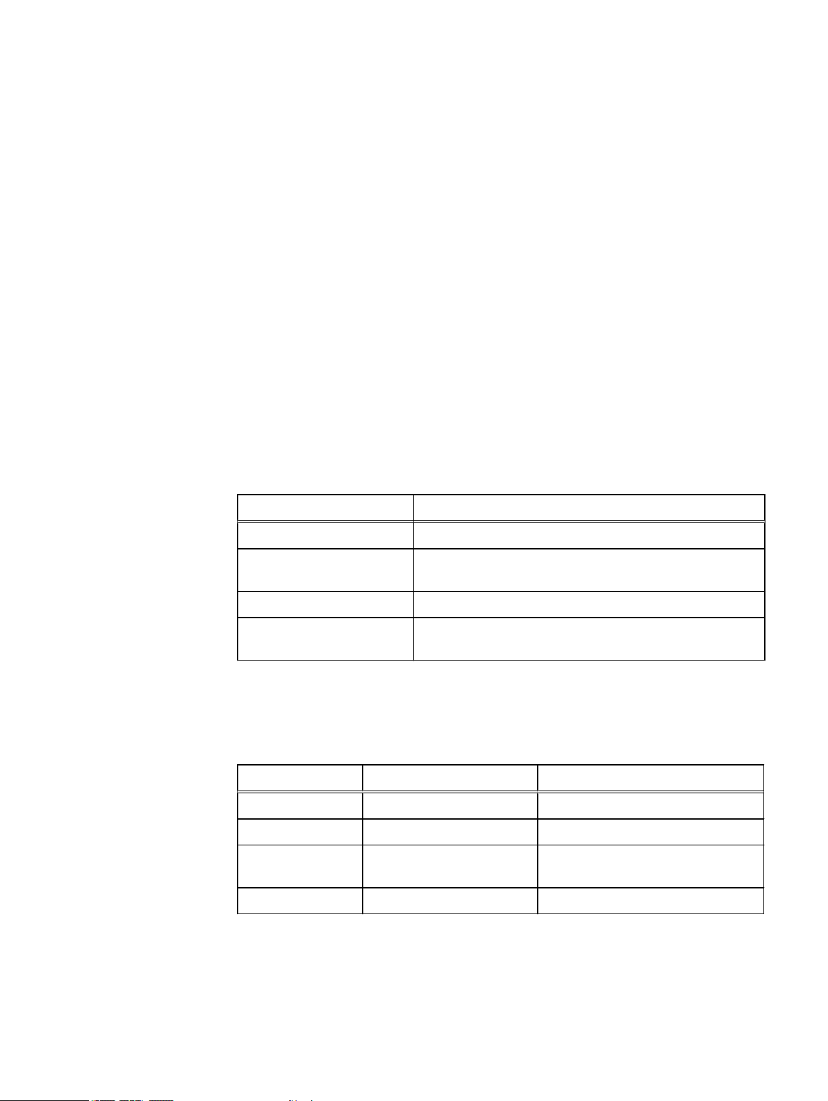
Table 1 Server power consumption and dissipation
Requirement Description
AC line voltage 90-264 V AC, autoranging, 47- 63 Hz
Power consumption
(operating maximum)
Heat dissipation 46.64 x 10⁵ J/hr (4421 BTU/hr) maximum
Maximum inrush current 55 A per power supply for 6 ms or less under typical line
Server dimensions and weight
Table 2 Server dimensions and weight
Dimension Server Server with rails
Height 3.46 in (8.79 cm) 2.0 U (with or without bezel)
Depth 28.86 in (73.3 cm) 28.86 in to 29.5 in (73.3 cm to 74.9 cm)
Width 17.24 in (43.8 cm) without
Maximum weight 71 lb (32.2 kg) 76 lb (34.47 kg)
Server placement requirements
1320 VA (1295 W) maximum (fully configured)
conditions and over the entire system ambient operating range
cabinet latch brackets
18.99 in (48.24 cm) with cabinet latch
brackets
There are no restrictions on the location of the server in the cabinet. Allow at least 36
inches of service clearance in front of the cabinet. Power distribution must support the
number of outlets required for the server and the server power rating listed on the Device
2
Page 3
Operating limits
®
EMC
SVR-I2U-H2316 Server Installation and Maintenance Guide
Rating label on the chassis. For additional information, refer to the preparation/planning
guides for your specific site and cabinet.
The ambient temperature specification is measured at the front bezel inlet. The site must
have air conditioning of the correct size and placement to maintain the specified ambient
temperature range and offset the heat dissipation listed in the table that follows.
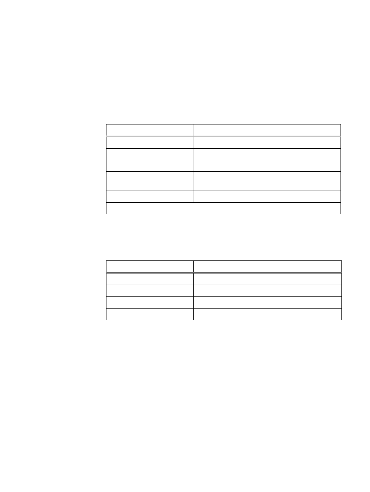
Table 3 Operating limits
Requirement Description
Ambient temperature 10°C to 35°C (50°F to 95°F)
Temperature gradient 10°C/hr (18°F/hr)
Relative humidity extremes 20% to 80% noncondensing
Recommended operating relative
humidity
Elevation -50 to 10,000 ft (-16 to 3,048 m)*
* For altitudes above 2,950 feet, the maximum operating temperature is de-rated 1°F/550 ft.
Shipping and storage requirements
Table 4 Shipping and storage requirements
Requirement Description
Ambient temperature -40°C to 65°C (-40°F to 149°F)
Temperature gradient 25°C/hr (45°F/hr)
Relative humidity 10% to 90% noncondensing
Elevation -50 to 35,000 ft (-16 to 10,600 m)
Installing the server in a cabinet
40% to 55% noncondensing
To install the server in a cabinet you must perform the tasks below in the order listed.
This section describes how to perform each task.
1. Review the warnings and recommendations section.
2. Verify the contents of the mounting kit.
3. Adjust the rail assemblies for the cabinet channel holes.
4. Remove the inner rails from the rail assemblies.
5. Attach the inner rails to the server.
6. Install the slide rails in the cabinet.
7. Install the server on the slide rails in the cabinet.
8. Connect cables to the server.
Operating limits 3
Page 4
9. Install the bezel on the server.
10. Power up the server.
Warnings and recommendations
The cabinet in which you will install the server must have a full earth ground to provide
reliable grounding. Also, the cabinet should have its own switchable power distribution.
We suggest that you use a cabinet that has dual power distribution units, one on each
side.
We recommend that you use cabinet anti-tip devices, especially if you are installing or
removing a server in the upper half of the cabinet when the lower half is empty.
Verifying the mounting kit parts
Verify that the server mounting kit includes the parts listed in the table that follows.
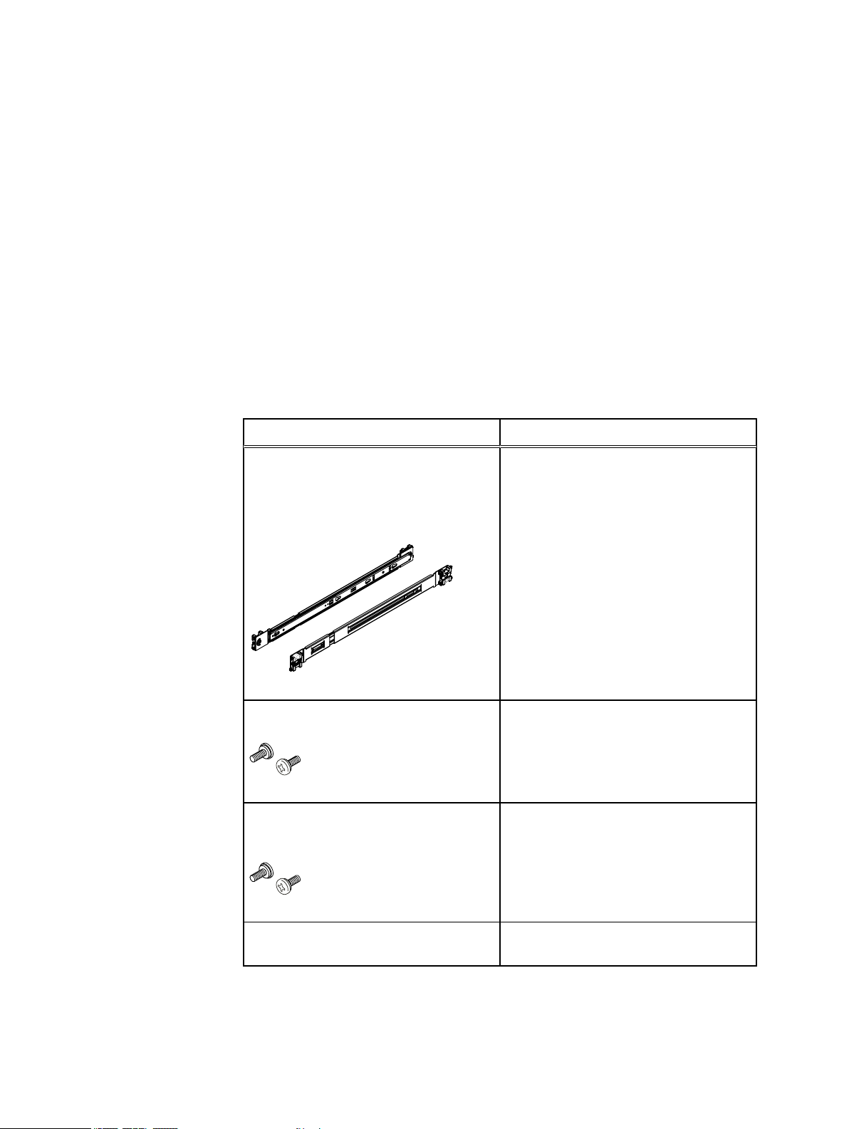
Table 5 Mounting kit parts
Component Use
2 universal rail assemblies
(consists of slide rails for connection to the
cabinet and inner rails for connection to
server)
Four Phillips pan-head 8-32 x 0.35 in screws
Two M5 mounting screws. (Presence is
dependant on when system was delivered)
Attach back to front on either side between
cabinet channels
Stabilize the server and rail mounting in
cabinet
Stabilize the server mounting in cabinet
4
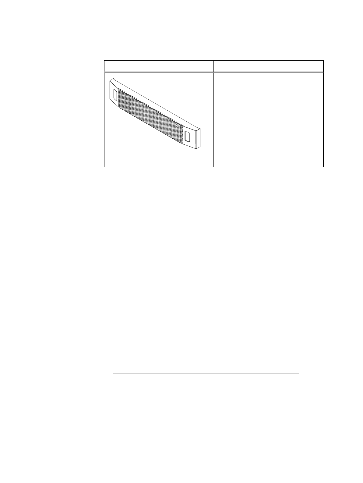
2U bezel (application specific)
Covers front of server in cabinet
Page 5
CL4973
Note
EMC® SVR-I2U-H2316 Server Installation and Maintenance Guide
Table 5 Mounting kit parts (continued)
Component Use
You need a # 2 Phillips-head screwdriver to complete the installation of the rails and
server.
Adjusting the rail assemblies for the cabinet channel holes
The rail assemblies ship with round alignment posts at the end of the rails for cabinet
channels (NEMA rails) with round holes. If your cabinet has channels with square holes,
switch the rail alignment posts to square posts.
Switching rail alignment posts
On each end of each rail assembly, switch the alignment post assembly using the
procedure that follows. Refer to Figure 1 on page 6 while performing the procedure.
Procedure
1. Remove the screw that secures the alignment post assembly.
2. Push the plastic tab on the alignment post assembly up or down, depending on the
rail end, and hold the tab in.
3. Rotate the alignment post assembly either clockwise to switch from round posts to
square posts or counter clockwise to switch from square posts to round posts until
the assembly clicks into place.
4. Secure the alignment post assembly in place with the screw that you removed.
The screw goes in the hole opposite the hole from which you removed it.
Adjusting the rail assemblies for the cabinet channel holes 5
Page 6
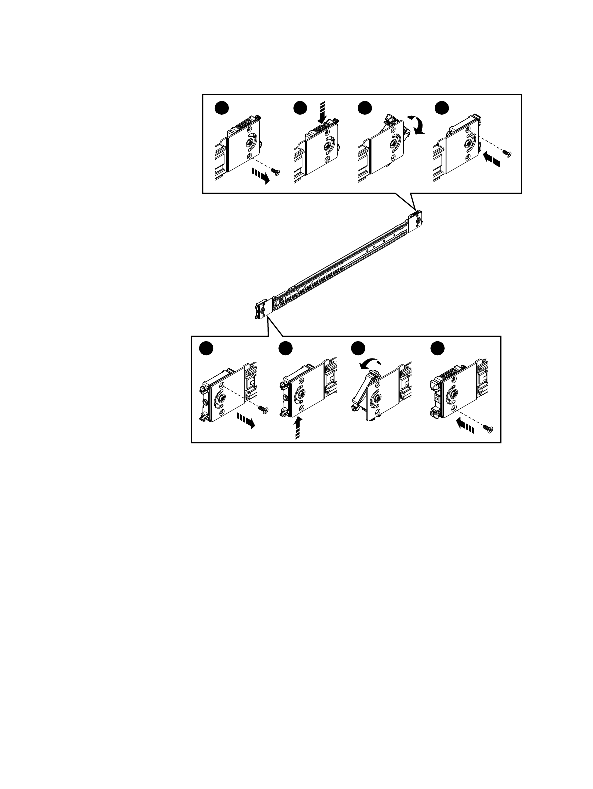
Figure 1 Switching from round rail alignment posts to square alignment posts
CL4951
1 32 4
1 32 4
Removing inner rails from the rail assemblies
Perform the procedure that follows on each rail assembly. Refer to Figure 2 on page 7
while performing the procedure.
Procedure
1. Slide the inner rail out from the slide rail as far as possible.
2. On the inner rail, slide the blue disconnect tab forward to release the inner rail from
the slide rail.
3. Slide the inner rail completely out of the slide rail.
6
Page 7

CL4883
3
1 2
®
EMC
SVR-I2U-H2316 Server Installation and Maintenance Guide
Figure 2 Removing the inner rail from the slide rail
Attaching the inner rails to the server
Attach an inner rail to each side of the server by performing the procedure that follows for
each rail. Refer to Figure 3 on page 8 while performing the procedure.
Procedure
1. With the flat side of the inner rail facing the side of the server, align the large end of
the rail notches of the inner rail with the connection studs on the server and push the
inner rail onto the connection studs.
2. Slide the inner rail forward along the server until the studs fit securely into the small
end of the rail notches.
An audible click indicates that the rail is secure.
Attaching the inner rails to the server 7
Page 8

Figure 3 Attaching an inner rail to the server
CL4988
1
2
CL5101
2U
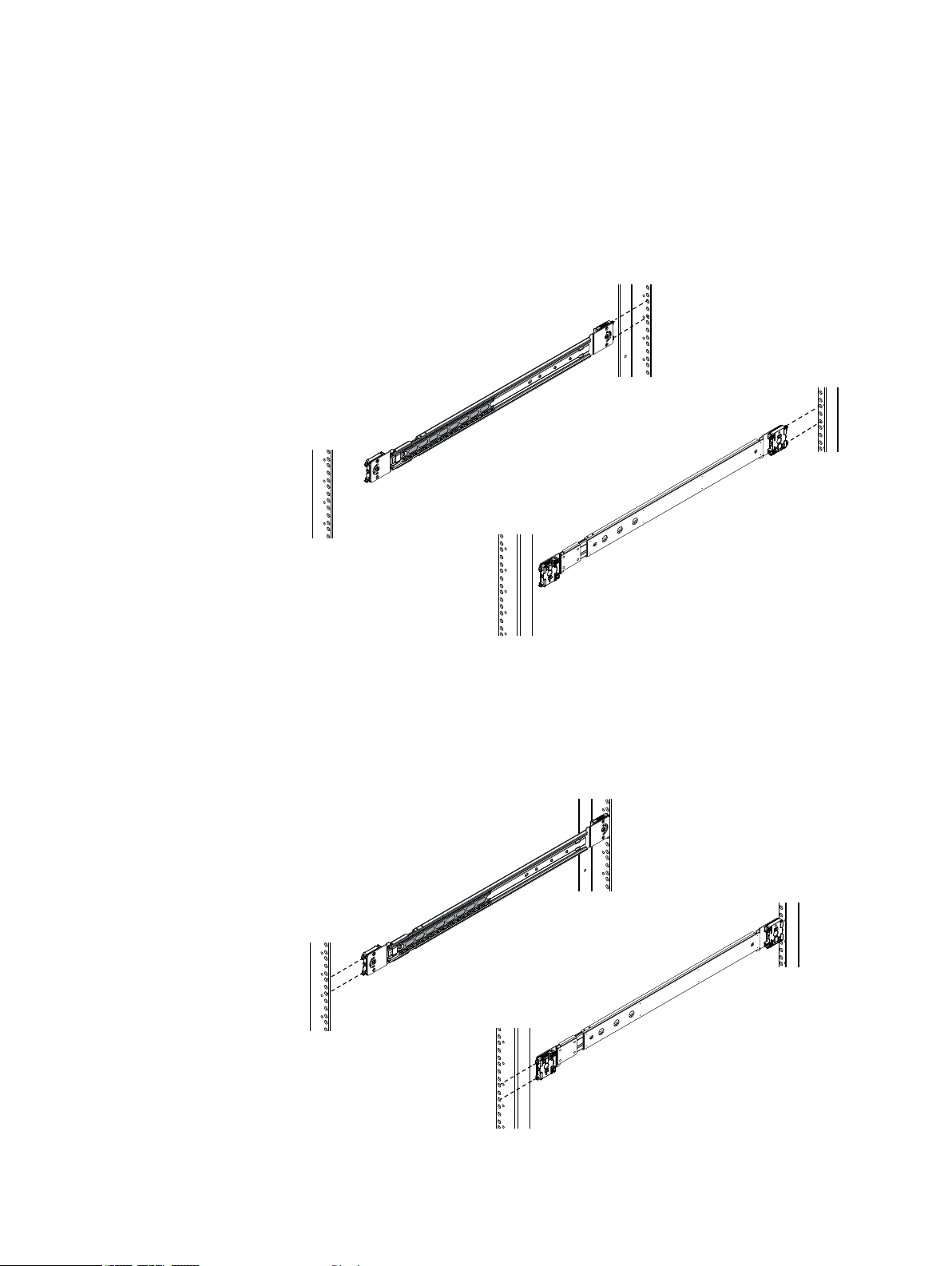
Installing the slide rails in the cabinet
The universal rail assemblies for this server support cabinets in which the front and rear
mounting channels are 24 inches to 34 inches apart. Each assembly contains a right and
a left slide rail.
Before you begin
Select the 2 U (3.5 in) of cabinet space for the server (Figure 4 on page 8).
Figure 4 Location for the rails in the 2U space for the server
8
Install each slide rail in the cabinet using the procedure that follows.
Page 9
CL5090
CL5091
EMC® SVR-I2U-H2316 Server Installation and Maintenance Guide
Procedure
1. From the front of the cabinet, align rail alignment posts with the rear channel holes for
the selected cabinet space for the server, and insert the alignment posts securely into
the holes (Figure 5 on page 9).
An audible click indicates that the connection is secure.
Figure 5 Inserting rail alignment posts into rear channel holes
2. Pull the slide rail forward so the front alignment posts go securely into the holes on
the front channel (Figure 6 on page 9).
An audible click indicates that the connection is secure.
Figure 6 Inserting rail alignment posts into front channel holes
Installing the slide rails in the cabinet 9
Page 10
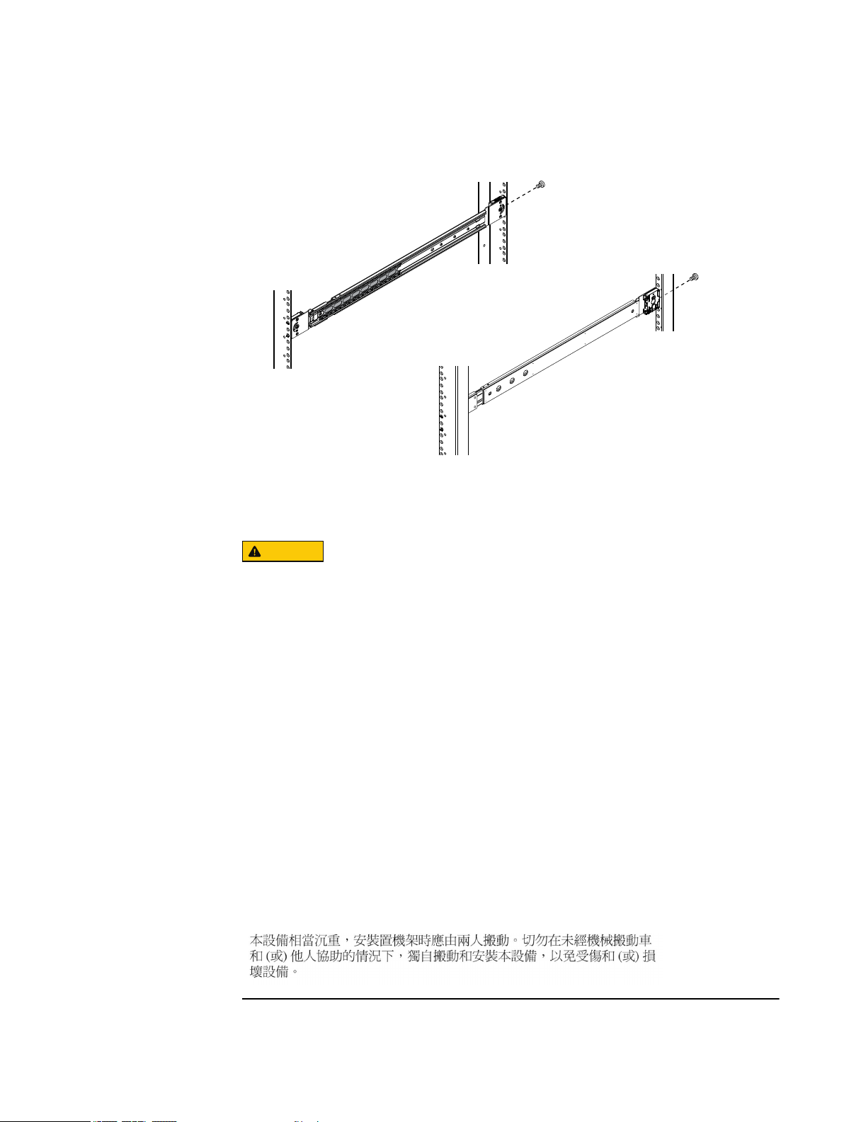
3. Secure the rail to the rear channel with a small stabilizer screw (Figure 7 on page
CL4854
CAUTION
10).
Figure 7 Installing stabilizer screws
Installing the server on the rails in the cabinet
The enclosure is heavy and should be installed into or removed from a rack by two
people. To avoid personal injury and/or damage to the equipment, do not attempt to lift
and install the enclosure into a rack without a mechanical lift and/or help from another
person.
L’armoire étant lourde, sa mise en place sur une rampe nécessite deux personnes. Afin
de ne pas vous blesser et/ou endommager le matériel, n’essayez pas de soulever et
d’installer l’armoire sur une rampe sans avoir recours à un relevage mécanique et/ou à
l’aide d’une autre personne.
Das Gehäuse ist schwer und sollte nur von zwei Personen in einem Rack installiert
werden. Zur Vermeidung von körperlichen Verletzungen und/oder der Beschädigung des
Gerätes, bitte das Gehäuse nicht ohne die Hilfe einer zweiten Person anheben und
einbauen.
Il contenitore è pesante e dev'essere installato nel rack da due persone. Per evitare
danni personali e/o all’apparecchiatura, non tentare di sollevare ed installare in un rack
il contenitore senza un sollevatore meccanico e/o l’aiuto di un’altra persona.
Debido a su considerable peso, la instalación del compartimento en el bastidor deben
realizarla siempre dos personas. Para evitar daños personales o en el equipo, el
compartimento no debe levantarse ni instalarse en el bastidor sin la ayuda de un
elevador mecánico o de otra persona.
10
Page 11
NOTICE
CL5092
Note
CL5093
Note
EMC® SVR-I2U-H2316 Server Installation and Maintenance Guide
When installing the server in the cabinet, do not pick the server up by its power/control
modules and do not push on its power/control modules. These modules are on either
side of the front of the server.
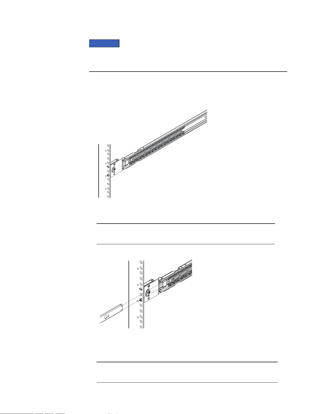
Procedure
1. On each slide rail bring the ball bearing retainer assembly fully to the front, so it rides
onto the security knob (Figure 8 on page 11).
Figure 8 Correct location for ball bearing retainer assembly
2. From the front of the cabinet, align the inner rails attached to the server with the white
plastic guide block on the front inside of each slide rail (Figure 9 on page 11).
For clarity Figure 9 on page 11 shows the inner rail without the server attached.
Figure 9 Aligning the inner rail with white plastic guide block
3. Slide the server into the cabinet so the inner rails extends over the plastic guide
blocks and the first part of the ball bearing retainer assemblies (Figure 10 on page
12).
For clarity Figure 10 on page 12 shows the inner rail without the server attached.
Installing the server on the rails in the cabinet 11
Page 12
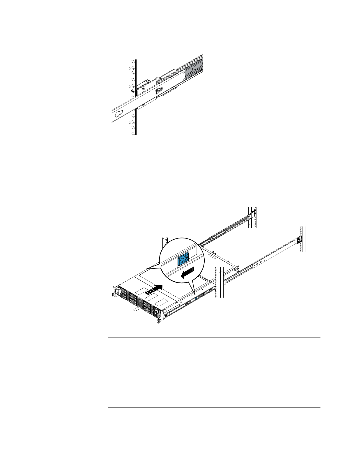
Figure 10 Inner rail over the first part of ball bearing retainer assembly
CL5094
CL4989
Note
4. Once the inner rails are properly engaged with the ball bearing retainer assemblies,
push the server into the cabinet until the slide rails are engaged and locked.
An audible click indicates that the slide rails are engaged and locked.
5. On the outside of each rail assembly, slide the blue disconnect tab forward to unlock
the server, and push the server completely into the cabinet (Figure 11 on page 12).
Figure 11 Inserting the server in the cabinet
12
Perform step 6 or step 7 as applicable to the quantity of stabilizer screws provided for
the server installation:
l
Perform step 6 if only two Phillips pan-head 8-32 screws are provided for securing
the server in the cabinet.
l
Perform step 7 if four screws (two Phillips pan-head 8-32 screws and two M5
mounting screws) are provided for securing the server in the cabinet.
6. To further secure the rail assembly and server in the cabinet, insert and tighten a
Phillips pan-head 8-32 screw directly behind each bezel latch (Figure 12 on page
13).
Page 13

CL4990
CL5575
®
EMC
SVR-I2U-H2316 Server Installation and Maintenance Guide
Figure 12 Installing the server with two stabilizer screws
7. To further secure the rail assembly and server in the cabinet:
a. Insert and tighten a Phillips pan-head 8-32 screw directly behind each bezel latch
(Figure 13 on page 13).
b. Insert and tighten an M5 mounting screw in the upper screw hole of each bracket
Figure 13 on page 13
Figure 13 Installing the server with four stabilizer screws
Connecting cables
Procedure
1. Plug the power cords into the power supplies and connect these cords to AC power
sources as described in the documentation for your product.
Connecting cables 13
Page 14

Installing the bezel
CL4991
Note
2. Attach any I/O cables as described in the documentation for your product.
Bezels are application specific, and may not appear as shown. Bezels may include a key
lock. All bezels include two tabs on either side that you press in to release the bezel and
its latches.
Refer to Figure 14 on page 14 while you perform the procedure that follows.
Procedure
1. Pushing on the ends, not the middle, of the bezel, press the bezel onto the latch
brackets until is snaps into place.
2. If the bezel has a key lock, lock the bezel with the provided key and store the key in a
secure place.
Figure 14 Installing the bezel
Powering up the server
Power up the server as described in the documentation for your product.
Maintaining the server
Only certain server components are addable or replaceable as field replaceable units
(FRUs). Should any non-FRU component fail you must replace the entire server. Refer to
your product documentation for information on which components are FRUs.
Before attempting to perform hardware service procedures, review your service contract
because replacement of some server components by unauthorized personnel may void
service warranties.
This document refers to hard drive modules as disk drive assemblies.
14
Page 15

Handling field replaceable units (FRUs)
This section describes the precautions that you must take and the general procedures
that you must follow when removing and storing any field replaceable unit (FRU). The only
FRUs in the server are the disk drive assemblies and power supply modules. Depending
on the product in which the server is used, the disk drive assemblies may be hotswappable; that is you can replace a disk drive assembly while the server is running. To
determine if disk drive assemblies are hot-swappable, refer to your product
documentation. Regardless of the product in which the server is used, the power supply
modules are hot-swappable; that is you can replace a power supply module while the
server is running.
You should not remove a faulty FRU until you have a replacement available.
When you replace FRUs, you can inadvertently damage the sensitive electronic circuits in
the equipment by simply touching them. Electrostatic charge (ESD) that has accumulated
on your body discharges through the circuits. If the air in the work area is very dry,
running a humidifier in the work area will help decrease the risk of ESD damage. Follow
the procedures below to prevent damage to the equipment.
l
Provide enough room to work on the equipment. Clear the work site of any
unnecessary materials or materials that naturally build up electrostatic charge, such
as foam packaging, foam cups, cellophane wrappers, and similar items.
l
Do not remove replacement or upgrade FRUs from their antistatic packaging until you
are ready to install them.
l
Before you service a server, gather together the ESD kit and all other materials you
will need. Once servicing begins, avoid moving away from the work site; otherwise,
you may build up an electrostatic charge.
l
Use the ESD kit when handling any FRU. Use an ESD wristband. To use the ESD
wristband (strap), attach the clip of the wristband to any bare (unpainted) metal on
the server; then put the wristband around your wrist with the metal button against
your skin. If an emergency arises and the ESD kit is not available, follow the
procedures in Emergency procedures (without an ESD kit) on page 15.
®
EMC
SVR-I2U-H2316 Server Installation and Maintenance Guide
Emergency procedures (without an ESD kit)
In an emergency when an ESD kit is not available, use the procedures below to reduce
the possibility of an electrostatic discharge by ensuring that your body and the
subassembly are at the same electrostatic potential. These procedures are not a
substitute for the use of an ESD kit. Follow them only in the event of an emergency.
l
Before touching any FRU, touch a bare (unpainted) metal surface of the cabinet or
server.
l
Before removing any FRU from its antistatic bag, place one hand firmly on a bare
metal surface of the server, and at the same time, pick up the FRU while it is still
sealed in the antistatic bag. Once you have done this do not move around the room
or touch other furnishings, personnel, or surfaces until you have installed the FRU.
l
When you remove a FRU from the antistatic bag, avoid touching any electronic
components and circuits on it.
l
If you must move around the room or touch other surfaces before installing a FRU,
first place the FRU back in the antistatic bag. When you are ready again to install the
FRU, repeat these procedures.
Handling field replaceable units (FRUs) 15
Page 16

Adding or replacing a compute node
NOTICE
CL5028
Each compute node is in special hot-swappable tray that fits in a node slot. Node slots
are accessible from the rear of the server. The locations of the node slots are as follows:
Node 4 Power supply 2 Node 3
Node 2 Power supply 1 Node 1
Depending on your product configuration, your server may ship with less than four
compute nodes and allows you to add additional nodes until the chassis is full. Filler
modules occupy slots without compute nodes.
To maintain proper system cooling, any node slot without a compute node installed must
be occupied by a filler module.
Adding a compute node
Before you add a compute node, review the section on handling field replaceable units
(FRUs).
To add a compute node to the server you must perform the tasks below in the order
listed. This section describes how to perform each task.
1. Remove the node filler module to expose the slot for the new node.
2. Unpack the new compute node.
3. Install the new compute node in the slot.
Removing a node filler module
Before you can install a compute node, you must remove the filler module from the slot
where you will install the node.
Procedure
1. At the rear of the server, locate the slot where you want to install the compute node.
2. While pushing the green latch to the right on the filler module in the slot, pull the filler
module out of the server by its handle (Figure 15 on page 16).
Figure 15 Removing a node filler module
16
Page 17

Unpacking a part
CL5026
Procedure
1. Attach an ESD wristband to your wrist and the enclosure in which you are installing
the part.
2. Unpack the part and place it on a static-free surface.
3. If the part is a replacement for a faulted part, save the packing material to return the
faulted part.
Installing a new compute node
Refer to Figure 16 on page 17while performing the procedure that follows.
Procedure
1. Align the compute node with chassis rail.
2. Push the node along the rail until the latch locks in position with a click.
3. Attach any needed cables to the compute node.
Figure 16 Installing a compute node
®
EMC
SVR-I2U-H2316 Server Installation and Maintenance Guide
Replacing a faulted compute node
Before you replace a faulted compute node, review the section on handling field
replaceable units (FRUs).
To replace a faulted compute node in the server you must perform the tasks below in the
order listed. This section describes how to perform each task.
1. Identify the faulted compute node.
2. Remove the faulted compute node.
3. Unpack the replacement compute node.
4. Install the replacement compute node.
Identifying a faulted compute node
Consult your product documentation on how to identify a faulted compute node in the
server. A faulted computed node may have an amber LED indication on:
l
The front console, which is visible when you remove the server’s bezel.
l
The rear of the compute node.
Replacing a faulted compute node 17
Page 18

Removing a faulted compute node
CL5025
Procedure
1. Unplug the cables attached to the faulted compute node.
2. While carefully pushing the green latch to the right on the faulted compute node, pull
the node out of the server by its handle (Figure 17 on page 18).
Figure 17 Removing a faulted compute node
Unpacking a part
Procedure
1. Attach an ESD wristband to your wrist and the enclosure in which you are installing
the part.
2. Unpack the part and place it on a static-free surface.
3. If the part is a replacement for a faulted part, save the packing material to return the
faulted part.
Installing a replacement compute node
Refer to Figure 18 on page 19 while performing the procedure that follows.
Procedure
1. Align the compute node with chassis rail.
2. Push the node along the rail until the latch locks in position with a click.
3. Attach the cables that you unplugged from the faulted compute node.
18
Page 19

Figure 18 Installing a compute node
CL5026
NOTICE
Replacing a disk drive assembly
A disk drive assembly consists of a hard disk drive supplied in special hot-swappable
hard-drive carrier that fits in a disk slot. Disk slots are accessible from the front of the
server. Refer to your product documentation to determine if a disk drive assembly is hotswappable.
®
EMC
SVR-I2U-H2316 Server Installation and Maintenance Guide
To maintain proper system cooling, any hard-drive bay without a disk drive assembly or
device installed must be occupied by filler module.
If a disk drive assembly is not hot-swappable, you may lose data when your replace a
disk drive assembly while the system is powered up and I/O is occurring. To determine if
disk drive assemblies are hot-swappable, refer to your product documentation.
Do not turn off or reboot your system while the drive is being formatted. Doing so can
cause a drive failure. Use appropriate ESD precautions, including the use of a grounding
strap, when performing the drive module replacement procedure.
To replace a disk drive assembly, you must perform the tasks below in the order listed.
The rest of the section describes how to perform each task.
1. Review the section on handling disk drive assemblies.
2. Identify the faulted disk drive assembly.
3. Remove the bezel from the server.
4. Replace the fault disk drive assembly.
5. Reinstall the bezel on the server.
Before you replace a disk drive assembly, review the section on handing field replaceable
units (FRUs).
Handling disk drive assemblies
l
Do not remove a disk drive filler until you have a replacement disk drive assembly
available to replace it.
l
Disk drive assemblies are sensitive to the extreme temperatures that are sometimes
encountered during shipping. We recommend that you leave the new disk drive
assembly in its shipping material and expose the package to ambient temperature for
Replacing a disk drive assembly 19
Page 20

at least four hours before attempting to use the new disk drive assemblies in your
CL4992
system.
l
Avoid touching any exposed electronic components and circuits on the disk drive
assembly.
l
Do not stack disk drive assemblies upon one another, or place them on hard
surfaces.
l
When installing multiple disk drive assemblies in a powered up system, wait at least
6 seconds before sliding the next disk drive assembly into position.
Identifying the faulted disk drive assembly
Consult your product documentation on how to identify a faulted disk assembly in the
server. A faulted disk drive assembly may have an amber LED indicator on its carrier,
which is visible when you remove the server’s bezel.
Removing the bezel
The front of the server may be covered by a bezel. Bezels are application specific, and
may not appear as shown. Bezels may include a key lock. If the server has a bezel,
remove it.
Refer to Figure 19 on page 20 while performing the procedure that follows.
Procedure
1. If the bezel has a key lock, unlock the bezel with the provided key.
2. Press the two tabs on either side of the bezel to release the bezel from its latches, and
pull the bezel off the latches.
Figure 19 Removing the bezel
Replacing a faulted disk drive assembly
Procedure
1. Attach an ESD wristband to your wrist and the server chassis.
20
Page 21

Note
CL4985
Note
®
EMC
SVR-I2U-H2316 Server Installation and Maintenance Guide
Use the method described in step 2 to remove any of the disk drive assemblies except
the two located behind the node control panel at right edge of the server. Use step 3
to remove either of the two disk drive assemblies that are located behind the node
control panel.
2. Remove a faulted disk drive assembly that is not located behind the right side node
control panel as follows (Figure 20 on page 21):
a. Press the green button on the left side of the disk drive assembly to unlock the
module’s lever.
b. Pull the lever open and slide the disk drive assembly from the server.
Figure 20 Removing the faulted disk drive assembly
The node control panel, at right edge of the server, slightly interferes with removal of
the two disk drive assemblies located behind it. As described in the following step,
grasping and pulling the left side edge of the disk drive assembly will allow it to freely
pass by the node control panel.
3. Remove a faulted disk drive assembly that is located behind the right side node
control panel as follows (Figure 21 on page 22):
a. Swing the node control panel outward to make the faulted disk drive assembly
accessible.
b. Press the green button on the left side of the disk drive assembly to unlock the
module’s lever.
c. Grasp the left side of the disk drive assembly and slide the disk drive assembly
from the server.
Replacing a faulted disk drive assembly 21
Page 22

Figure 21 Removing the faulted disk drive assembly
CL5576
1 2 3
CL4984
B
A
4. Unpack the replacement disk drive assembly and save the packing material for
returning the faulted disk drive assembly.
5. Install the replacement disk drive assembly (Figure 22 on page 22):
a. With the lever on the replacement disk drive assembly in the fully open position
(green button to the right), slide the module into the server.
b. When the lever begins to close by itself, push on the lever to lock it into place.
Figure 22 Installing the replacement disk drive assembly
6. Remove and store the ESD wristband.
Reinstalling the bezel
If a bezel covered the front of the server, reinstall the bezel using the procedure that
follows. Refer to Figure 23 on page 23 while performing the procedure.
Procedure
1. Pushing on the ends, not the middle, of the bezel, press the bezel onto the latch
brackets until is snaps into place.
22
2. If the bezel has a key lock, lock the bezel with the provided key and store the key in a
secure place.
Page 23

Figure 23 Installing the bezel
CL4991
®
EMC
SVR-I2U-H2316 Server Installation and Maintenance Guide
Replacing a power supply
The power supplies are accessible from the rear of the server.
Before you use the procedure that follows to replace a faulted disk drive assembly,
review the section on handing field replaceable units (FRUs).
Identifying a faulted power supply
Consult your product documentation on how to identify a faulted power supply in the
server. A faulted power supply may have an amber LED indicator, which is visible from the
rear of the server.
Replacing a faulted power supply
Procedure
1. Undo the retaining clip securing the power supply’s AC power cord, and unplug the
cord.
2. While carefully pushing the green latch to the left on the faulted power supply, pull
the supply out of the server by its handle (Figure 24 on page 24).
Replacing a power supply 23
Page 24

Figure 24 Removing a power supply
CL4986
CL4987
3. Unpack the replacement power supply and place it on a clean, static-free surface near
the server.
4. While carefully pushing the green latch to the left on the replacement power supply,
push the supply into the power supply cage until it clicks into place (Figure 25 on
page 24).
Figure 25 Installing a power supply
5. Plug in the power supply’s AC power cord and fasten the retaining clip to secure the
cord.
Replacing the server
Replacement of non-FRU server components by unauthorized personnel may void service
warranties. Refer to your product documentation for information on which components
are FRUs. Should any non-FRU component fail you must replace the entire server.
To replace the server perform the tasks below in the order listed. The rest of this section
describes how to perform each task.
1. Power off the server.
2. Disconnect the cables from the server.
3. Remove the bezel from the server.
4. Remove the server from the cabinet.
5. Remove the inner rails from the server.
24
Page 25

6. Unpack the replacement server.
7. Attach the inner rails to the replacement server.
8. Install the replacement server on the rails in the cabinet.
9. Reconnect the cables that you removed from the original server to the replacement
server.
10. Reinstall the bezel on the replacement server.
11. Power up the replacement server.
Powering off the server
Before removing the server from the cabinet, power it off as described in the
documentation for your product.
Disconnecting cables from the server
Procedure
1. Unplug all power cords and I/O cables from the back of the server.
2. Label each cord and cable so you can easily identify them when you need to plug
them into the replacement server.
®
EMC
SVR-I2U-H2316 Server Installation and Maintenance Guide
Removing the bezel
The front of the server may be covered by a bezel. Bezels are application specific, and
may not appear as shown. Bezels may include a key lock. If the server has a bezel,
remove it.
Refer to Figure 26 on page 26 while performing the procedure that follows.
Procedure
1. If the bezel has a key lock, unlock the bezel with the provided key.
2. Press the two tabs on either side of the bezel to release the bezel from its latches, and
pull the bezel off the latches.
Powering off the server 25
Page 26

Figure 26 Removing the bezel
CL4992
CAUTION
Removing the server from the cabinet
The enclosure is heavy and should be installed into or removed from a rack by two
people. To avoid personal injury and/or damage to the equipment, do not attempt to lift
and install the enclosure into a rack without a mechanical lift and/or help from another
person.
L’armoire étant lourde, sa mise en place sur une rampe nécessite deux personnes. Afin
de ne pas vous blesser et/ou endommager le matériel, n’essayez pas de soulever et
d’installer l’armoire sur une rampe sans avoir recours à un relevage mécanique et/ou à
l’aide d’une autre personne.
Das Gehäuse ist schwer und sollte nur von zwei Personen in einem Rack installiert
werden. Zur Vermeidung von körperlichen Verletzungen und/oder der Beschädigung des
Gerätes, bitte das Gehäuse nicht ohne die Hilfe einer zweiten Person anheben und
einbauen.
Il contenitore è pesante e dev'essere installato nel rack da due persone. Per evitare
danni personali e/o all’apparecchiatura, non tentare di sollevare ed installare in un rack
il contenitore senza un sollevatore meccanico e/o l’aiuto di un’altra persona.
Debido a su considerable peso, la instalación del compartimento en el bastidor deben
realizarla siempre dos personas. Para evitar daños personales o en el equipo, el
compartimento no debe levantarse ni instalarse en el bastidor sin la ayuda de un
elevador mecánico o de otra persona.
26
Page 27

NOTICE
Note
CL5575
®
EMC
SVR-I2U-H2316 Server Installation and Maintenance Guide
When removing the server from the cabinet, do not hold the server up by its power/
control module, which is on the right side of the front of the server.
The illustration in step 1 (Figure 27 on page 27) shows that the server is secured in the
cabinet with four stabilizing screws. Depending on when it was installed, the server you
are replacing may be secured with only the lower two stabilizing screws behind the latch
brackets.
Procedure
1. Remove the stabilizing screws that secure the server in the cabinet (Figure 27 on page
27).
Figure 27 Removing the stabilizer screws
2. Pull the server forward until it locks in place (Figure 28 on page 28).
Removing the server from the cabinet 27
Page 28

Figure 28 Sliding server out of the cabinet to the locked position
CL4993
NOTICE
CL4994
3. Slide the blue disconnect tabs forward to release the inner rails from the slide rails
(Figure 29 on page 28).
Once you release the server from the inner rails, you must support the full weight of
the server.
4. Being prepared to support the full weight of the server, slowly pull the server forward
and remove it from the cabinet (Figure 29 on page 28).
Figure 29 Releasing the inner rail locks and removing the server from the cabinet
Removing the inner rails from the server
Use the procedure that follows to remove each inner rail from the server. Refer to Figure
30 on page 29 while performing the procedure.
28
Page 29

CL4995
1
2
®
EMC
SVR-I2U-H2316 Server Installation and Maintenance Guide
Procedure
1. On the middle of the inner rail, push in and hold the metal latch, and push the rail
backward to release the connection studs from the small end of the rail notches.
2. When the connections studs are in the large end of the rail notches, release the metal
latch and pull the inner rail away from the server.
Figure 30 Releasing the inner rails from the server
Unpacking a part
Procedure
1. Attach an ESD wristband to your wrist and the enclosure in which you are installing
the part.
2. Unpack the part and place it on a static-free surface.
3. If the part is a replacement for a faulted part, save the packing material to return the
faulted part.
Attaching the inner rails to the server
Attach an inner rail to each side of the server by performing the procedure that follows for
each rail. Refer to Figure 31 on page 30 while performing the procedure.
Unpacking a part 29
Page 30

Procedure
CL4988
1
2
1. With the flat side of the inner rail facing the side of the server, align the large end of
the rail notches of the inner rail with the connection studs on the server and push the
inner rail onto the connection studs.
2. Slide the inner rail forward along the server until the studs fit securely into the small
end of the rail notches.
An audible click indicates that the rail is secure.
Figure 31 Attaching an inner rail to the server
30
Page 31

Installing the server on the rails in the cabinet
CAUTION
NOTICE
The enclosure is heavy and should be installed into or removed from a rack by two
people. To avoid personal injury and/or damage to the equipment, do not attempt to lift
and install the enclosure into a rack without a mechanical lift and/or help from another
person.
L’armoire étant lourde, sa mise en place sur une rampe nécessite deux personnes. Afin
de ne pas vous blesser et/ou endommager le matériel, n’essayez pas de soulever et
d’installer l’armoire sur une rampe sans avoir recours à un relevage mécanique et/ou à
l’aide d’une autre personne.
Das Gehäuse ist schwer und sollte nur von zwei Personen in einem Rack installiert
werden. Zur Vermeidung von körperlichen Verletzungen und/oder der Beschädigung des
Gerätes, bitte das Gehäuse nicht ohne die Hilfe einer zweiten Person anheben und
einbauen.
Il contenitore è pesante e dev'essere installato nel rack da due persone. Per evitare
danni personali e/o all’apparecchiatura, non tentare di sollevare ed installare in un rack
il contenitore senza un sollevatore meccanico e/o l’aiuto di un’altra persona.
Debido a su considerable peso, la instalación del compartimento en el bastidor deben
realizarla siempre dos personas. Para evitar daños personales o en el equipo, el
compartimento no debe levantarse ni instalarse en el bastidor sin la ayuda de un
elevador mecánico o de otra persona.
®
EMC
SVR-I2U-H2316 Server Installation and Maintenance Guide
When installing the server in the cabinet, do not pick the server up by its power/control
modules and do not push on its power/control modules. These modules are on either
side of the front of the server.
Procedure
1. On each slide rail bring the ball bearing retainer assembly fully to the front, so it rides
onto the security knob (Figure 32 on page 32).
Installing the server on the rails in the cabinet 31
Page 32

Figure 32 Correct location for ball bearing retainer assembly
CL5092
Note
CL5093
Note
2. From the front of the cabinet, align the inner rails attached to the server with the white
plastic guide block on the front inside of each slide rail (Figure 33 on page 32).
For clarity Figure 33 on page 32 shows the inner rail without the server attached.
Figure 33 Aligning the inner rail with white plastic guide block
32
3. Slide the server into the cabinet so the inner rails extends over the plastic guide
blocks and the first part of the ball bearing retainer assemblies (Figure 34 on page
33).
For clarity Figure 34 on page 33 shows the inner rail without the server attached.
Page 33

CL5094
CL4989
Note
®
EMC
SVR-I2U-H2316 Server Installation and Maintenance Guide
Figure 34 Inner rail over the first part of ball bearing retainer assembly
4. Once the inner rails are properly engaged with the ball bearing retainer assemblies,
push the server into the cabinet until the slide rails are engaged and locked.
An audible click indicates that the slide rails are engaged and locked.
5. On the outside of each rail assembly, slide the blue disconnect tab forward to unlock
the server, and push the server completely into the cabinet (Figure 35 on page 33).
Figure 35 Inserting the server in the cabinet
Perform step 6 or step 7 as applicable to the quantity of stabilizer screws provided for
the server installation:
l
Perform step 6 if only two Phillips pan-head 8-32 screws are provided for securing
the server in the cabinet.
l
Perform step 7 if four screws (two Phillips pan-head 8-32 screws and two M5
mounting screws) are provided for securing the server in the cabinet.
6. To further secure the rail assembly and server in the cabinet, insert and tighten a
Phillips pan-head 8-32 screw directly behind each bezel latch (Figure 36 on page
34).
Installing the server on the rails in the cabinet 33
Page 34

Figure 36 Installing the server with two stabilizer screws
CL4990
CL5575
7. To further secure the rail assembly and server in the cabinet:
a. Insert and tighten a Phillips pan-head 8-32 screw directly behind each bezel latch
(Figure 37 on page 34).
b. Insert and tighten an M5 mounting screw in the upper screw hole of each bracket
Figure 37 on page 34
Figure 37 Installing the server with four stabilizer screws
Reconnecting cables
34
Plug all power and I/O cables that you removed from the original server into the back of
the replacement server.
Page 35

Reinstalling the bezel
CL4991
®
EMC
SVR-I2U-H2316 Server Installation and Maintenance Guide
If a bezel covered the front of the server, reinstall the bezel using the procedure that
follows. Refer to Figure 38 on page 35 while performing the procedure.
Procedure
1. Pushing on the ends, not the middle, of the bezel, press the bezel onto the latch
brackets until is snaps into place.
2. If the bezel has a key lock, lock the bezel with the provided key and store the key in a
secure place.
Figure 38 Installing the bezel
Powering up the server
Power up the server as described in the documentation for your product.
Removing the slide rails from the cabinet
If you ever need to remove the rails from the cabinet, use the procedure that follows.
Procedure
1. On each rail, remove the small stabilizer screw that secures the rail to the rear
channel (Figure 39 on page 36).
Reinstalling the bezel 35
Page 36

Figure 39 Removing the rear stabilizing screws
CL4854
2. Release each rail from the channels (Figure 40 on page 37):
a. At each rail end, push and hold the alignment posts together.
b. Slide the rail out of the channel, and remove it from the cabinet.
36
Page 37

CL4856
Rear
A B
EMC® SVR-I2U-H2316 Server Installation and Maintenance Guide
Figure 40 Releasing the rail from the cabinet channels
Removing the slide rails from the cabinet 37
Page 38

Copyright © 2012-2015 EMC Corporation. All rights reserved. Published in USA.
Published March, 2015
EMC believes the information in this publication is accurate as of its publication date. The information is subject to change without
notice.
The information in this publication is provided as is. EMC Corporation makes no representations or warranties of any kind with
respect to the information in this publication, and specifically disclaims implied warranties of merchantability or fitness for a
particular purpose. Use, copying, and distribution of any EMC software described in this publication requires an applicable software
license.
EMC², EMC, and the EMC logo are registered trademarks or trademarks of EMC Corporation in the United States and other countries.
All other trademarks used herein are the property of their respective owners.
For the most up-to-date regulatory document for your product line, go to EMC Online Support (https://support.emc.com).
38
 Loading...